


Installatio n Instructions
Retractable Ventilation System
Instrucciones de Instalación
Sistema de ventilación retráctil
Instructions d’installation
Système de ventilation rétractable
|
|
|
|
|
|
|
|
|
|
|
|
|
|
E30DD75ESS |
E36DD75ESS |
E46DD75ESS |
E48DD75ESS |
5995426227 |
||
|
|
|
|
|
|
|

2 FindingInformation
Attach your sales receipt to this page for future reference.
READ AND SAVE THESE INSTRUCTIONS
NOTE
Installer: Leave instructions with owner.
Owner: Read your Retractable Ventilation System Use & Care Manual. It contains important safety information for operating this appliance. It also has many suggestions for getting the best results from your downdraft vent.
Read all instructions before installing the downdraft vent.
For your safety, please read and observe all safety instructions. This guide will help you anticipate all installation connections.
QUESTIONS?
For toll-free telephone support in the U.S. and Canada:
1-877- 4ELECTROLUX (1-877-435-3287)
For online support and Internet product information:
www.electroluxusa.com
©2004 Electrolux Home Products, Inc.
Post Office Box 212378, Augusta, Georgia 30917, USA All rights reserved. Printed in the USA

FindingInformation 3
TABLE OF CONTENTS |
|
Finding Information ........................................... |
2 |
Please Read And Save This Guide ................... |
2 |
Questions .......................................................... |
2 |
Table Of Contents .............................................. |
3 |
Safety ................................................................... |
4 |
Important Safety Instructions .............................. |
4 |
Safety Precautions ............................................. |
5 |
Preparing for Installation .................................. |
7 |
Verifying Package Contents ............................... |
7 |
Installation Planning ........................................... |
7 |
Specifications and Dimensions ........................... |
8 |
Electrical Power Supply ..................................... |
9 |
Requirements .................................................... |
9 |
Duct Preparation ............................................... |
10 |
Duct Installation ................................................ |
10 |
Countertop Preparation ................................... |
13 |
Preparing the Countertop ................................ |
13 |
Installation ........................................................ |
16 |
Installing the Downdraft Vent ............................ |
16 |
Connecting the Exhaust Duct ........................... |
16 |
Making the Electrical Connection ..................... |
17 |
Installing with a Cooktop/Range ....................... |
18 |
Operation ........................................................... |
19 |
Verifying the Operation .................................... |
19 |
4 Safety
IMPORTANT SAFETY INSTRUCTIONS
Safety Precautions
Do not attempt to install or operate your unit until you have read the safety precautions in this manual. Safety items throughout this manual are labeled with a Warning or Caution based on the risk type.
Definitions
! This is the safety alert symbol. It is used to alert you to potential personal injury hazards. Obey all safety messages that follow this symbol to avoid possible injury or death.
! WARNING
WARNING indicates a potentially hazardous situation which, if not avoided, could result in death or serious injury.
! CAUTION
CAUTION indicates a potentially hazardous situation which, if not avoided, may result in minor or moderate injury.
CAUTION
CAUTION used without the safety alert symbol indicates a potentially hazardous situation which, if not avoided, may result in property damage.
IMPORTANT
Indicates installation, operation or maintenance information which is important but not hazard related.

Safety 5
SAFETY PRECAUTIONS
!WARNING
•To reduce the risk of fire, electric shock, or injury to persons, observe the following:
a)Installation work and electrical wiring must be done by qualified person(s) in accordance with all applicable codes and standards, including fire-rated construction.
b)Sufficient air is needed for proper combustion and exhausting of gases through the flue (chimney) of fuel burning equipment to prevent back drafting. Follow the heating equipment manufacturer’s guidelines and safety standards such as those published by the National Fire Protection Association (NFPA), and the American Society for Heating, Refrigeration and Air Conditioning Engineers (ASHRAE), and the local code authorities.
c)When cutting or drilling into wall or ceiling, do not damage electrical wiring and other hidden utilities.
d)Ducted fans must always be vented outdoors.
e)Use this unit only in the manner intended by the manufacturer. If you have questions, contact the manufacturer.
•To reduce the risk of fire, use only metal ductwork.
•Grounding Instructions
This appliance must be grounded. In the event of an electrical short circuit, grounding reduces the risk of electric shock by providing an escape wire for the electric current. This appliance is equipped with a cord having a grounding wire with a grounding plug. The plug must be plugged into an outlet this is properly installed and grounded.
•Improper grounding can result in a risk of electric shock.
•Consult a qualified electrician if the grounding instructions are not completely understood, or if doubt exists as to whether the appliance is properly grounded.
•Do not use an extension cord. If the power supply cord is too short, have a qualified electrician install an outlet near the appliance.

6 Safety
! CAUTION
To reduce the risk of fire and electric shock, install this retractable ventilation unit only with remote blower models rated maximum 8 amp (total of all interconnected remote blowers).

PreparingforInstallation 7
VERIFY PACKAGE CONTENTS
•Use & Care Guide
•Anchoring Legs and Hardware
INSTALLATION PLANNING
A qualified technician must complete the installation of this appliance. Proper installation is your responsibility.
Sufficient air is needed for proper combustion and exhausting of gases through the flue (chimney) of fuel burning equipment to prevent back drafting. Follow the heating equipment manufacturer’s guideline and safety standards such as those published by he national Fire Protection Association (NFPA), and the American Society for Heating, Refrigeration and Air Conditioning Engineers (ASHRAE), and the local code authorities.
Plan the installation so that all required minimum clearances between the cooktop, overhead cabinets and adjacent vertical walls are provided. Refer to the cooktop/ range installation instructions for the minimum dimensions specific to the particular appliance being installed.
The vent system is designed to remove the contaminants and by-products that result when cooking with gas or electric appliances. The vent system consists of the vent intake along with a remote blower. The raised vent downdraft systems are compatible for use with select cooktops and ranges, therefore, these instructions offer specific guidelines for mounting the raised vents behind cooktops and ranges.
Make sure that you have everything needed to complete the installation before proceeding.
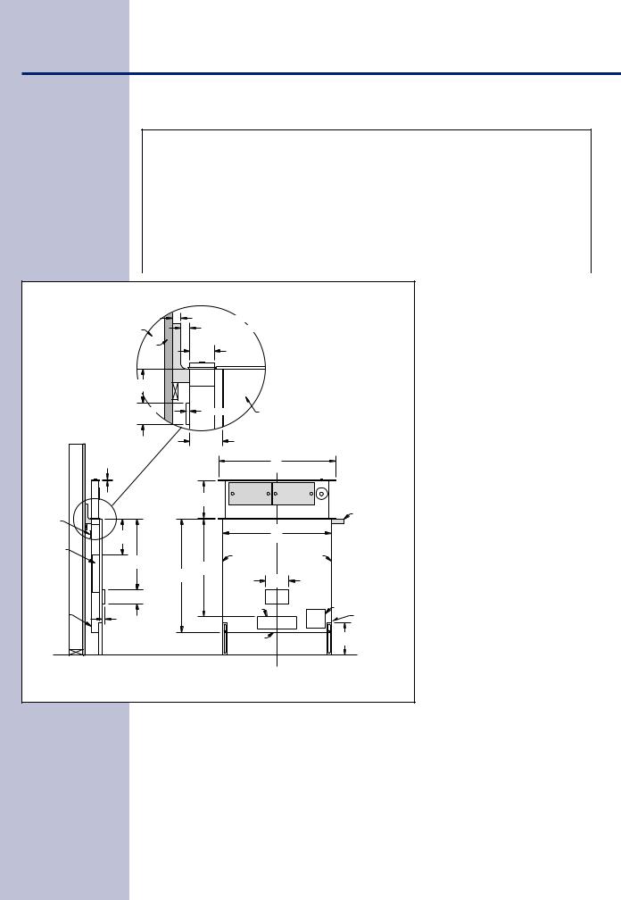
8 SpecificationsandDimensions
Raised Vent System Specifications
Raised Vent Model No. |
For Use With Gas Cooktops |
Duct Size |
|
|
|
|
|
E30DD75ESS |
E30GC64ESS |
3 1/4”x10” & 10” |
|
|
|
|
|
E36DD75ESS |
E36GC65ESS |
3 1/4”x10” & 10” |
|
|
|
|
|
E46DD75ESS |
E46GC66ESS/E46GC67ESS |
3 1/4”x10” & 10” |
|
|
|
|
|
E48DD75ESS |
E46GC66ESS/E46GC67ESS |
3 1/4”x10” & 10” |
|
|
|
|
|
|
|
|
3/4" (19mm) Max. backsplash thickness |
|
||
|
Stud wall |
|
1/4" (6mm) Min. flat area |
|
|
|
|
|
|
|
|
|
|
|
Wall board |
|
|
|
|
|
|
|
|
2 1/8" |
|
|
|
|
|
|
(54mm) |
|
|
|
|
3" |
|
|
|
|
|
|
(76mm) |
|
|
|
|
|
|
1 15/16" |
|
9/32" (7mm) |
Cooktop/Range |
|
|
|
(49mm) |
|
|
|||
|
|
|
|
|
|
|
|
|
|
2 13/16" |
|
|
|
|
|
|
(71mm) |
|
|
|
|
3/8" |
|
|
|
A |
|
|
(10mm) |
|
|
|
|
|
|
|
|
10" |
|
|
|
|
|
|
(254mm) |
|
|
|
|
|
|
|
|
|
Countertop |
Stiffener |
|
|
|
|
|
|
|
6 5/8" |
|
|
|
B |
|
|
|
|
|
|
|
|
|
(168mm) |
|
|
|
|
|
1 5/8" x 16" |
|
|
1 5/8" x 16" |
|
1 5/8" x 16" |
|
Exhaust duct |
|
|
|
|
||
|
|
Exhaust duct |
Exhaust duct |
|
||
|
22 1/2" |
|
|
|||
|
|
|
|
|
|
|
|
(572mm) |
|
25 7/8" |
|
|
|
|
|
30" |
(657mm) |
|
|
|
|
|
(762mm) |
|
6" |
|
|
|
|
|
|
|
(152mm) |
|
|
3 3/4" |
|
|
|
Motor |
|
|
(95mm) |
|
3 1/4" x 10" |
|
cover |
Electrical |
|
|
|
Rear |
|
|
access panel |
3 1/4" x 10" |
|
|
|
|
|
|
|
|
Exhaust duct |
|
|
|
|
Exhaust duct |
3/4" (19mm) |
|
|
|
|
48", 3 prong grounded |
|
|
|
|
|
power cord |
|
|
|
|
|
|
|
|
|
|
|
1 5/8" x 16" |
|
8 1/2" |
|
|
|
|
|
(216mm) |
||
|
|
|
Exhaust duct |
|
||
|
|
|
|
|
||
|
Finished floor |
|
|
|
|
|
|
|
|
Figure 1 |
|
|
|
|
Model |
Width “A” |
Width “B” |
|
|
|
|
|
E30DD75ESS |
30” (762mm) |
27 3/4” (705mm) |
|
|
|
|
|
E36DD75ESS |
36” (914mm) |
33 3/4” (857mm) |
|
|
|
|
|
E46DD75ESS |
46” (1168mm) |
43 3/8” (1102mm) |
|
|
|
|
|
E48DD75ESS |
48” (1219mm) |
43 3/8” (1102mm) |
|
|
|
|
|
|
|
|

ElectricalPowerSupply 9
REQUIREMENTS
! WARNING
Failure to disconnect power may result in electrical shock or fire hazard! If the electric service provided does not meet the product specifications, do not proceed with the installation. Call the selling dealer or a licensed electrician.
It is the owner’s responsibility to ensure that the electrical connection of this appliance is performed by a qualified electrician. The electrical installation, including minimum supply wire size and grounding, must be in accordance with the National Electric code ANSI/NFPA 70-1993* (or latest revision) and local codes and ordinances.
A copy of this standard may be obtained from:
National Fire Protection Association
1 Batterymarch Park
Quincy, Massachusetts 02269-9101
The correct 120VAC, 60Hz, 15A circuit must be supplied for this appliance from a separate, grounded, circuit that is protected by a properly sized circuit breaker or time delay fuse.

10 DuctPreparation
DUCT INSTALLATION
!WARNING
•To reduce the risk of fire and to properly exhaust air, ducted fans must be vented to outside. Do not vent exhaust air into spaces within walls, ceilings, attics, crawl spaces or garages.
•Improper installation, adjustment, alteration, service, or maintenance can cause personal injury or property damage.
•To reduce the risk of fire, use only duct work materials deemed acceptable by state, municipal and local codes.
IMPORTANT
•Best performance is achieved by using round duct instead of rectangular, especially when elbows are required.
•If multiple elbows are needed, ensure that there is a minimum of 24” of straight duct between any two elbows.
•Avoid “S” or “back to back” configurations caused by adjacent elbows.
•Thermal breaks, such as a short section of non-metallic duct, should be used in areas of extreme cold.
•A back-draft damper at the duct outlet may also be required.
•Do not use flexible metal duct.
•Do not use duct work that is smaller in cross-sectional area than the recommended size duct.
•Do not rely on duct tape alone to seal duct joints. Use sheet metal screws as require to support the duct weight.
•The vent hood and cooking appliance(s) must be removable if service is required.
•Be certain that the duct work does not interfere with floor joists or wall studs.
•It is important to keep a minimum number of turns in the duct run, and to keep the run as short as possible.
•Do not restrict the air flow by reducing the duct cross-sectional areas when making hard joints or squeezing through a tight area.
•With concrete slab construction, “box-in” the duct work to prevent it from collapsing when the wet concrete is poured. Also allow room for electrical conduit.
•Cross-drafts or air currents caused by adjacent open windows or doors, HVAC outlets, and ceiling fans reduce vent efficiency.
 Loading...