

Page 1
DI9966-M
Innebygget kjøkkenvifte (sugeversjon) med fl at uttrekkbar
Utsugande köksfläkt för inbyggnad med platt utdragbar
skärm
skjerm
Emhætte til indbygning med flad, udtagelig skærm
Keittiökaapistoon asennettava etulevyllinen
poistoilmatuuletin
Anvisningar för montering och användning
Instruksjoner for montering og bruk
Monterings- og brugsanvisninger
Asennus- ja käyttöohjeet
Page 2

FR DE NL ES PT
INDEX
RECOMMENDATIONS AND SUGGESTIONS......................................................................................................................3
CHARACTERISTICS..............................................................................................................................................................4
INSTALLATION ......................................................................................................................................................................6
USE.......................................................................................................................................................................................10
MAINTENANCE....................................................................................................................................................................11
EN
SOMMAIRE
CONSEILS ET SUGGESTIONS ..........................................................................................................................................14
CARACTERISTIQUES.........................................................................................................................................................15
INSTALLATION ....................................................................................................................................................................17
UTILISATION........................................................................................................................................................................21
ENTRETIEN..........................................................................................................................................................................22
INHALTSVERZEICHNIS
EMPFEHLUNGEN UND HINWEISE....................................................................................................................................25
CHARAKTERISTIKEN..........................................................................................................................................................26
MONTAGE............................................................................................................................................................................28
BEDIENUNG.........................................................................................................................................................................32
WARTUNG............................................................................................................................................................................33
INHOUDSOPGAVE
ADVIEZEN EN SUGGESTIES.............................................................................................................................................36
EIGENSCHAPPEN...............................................................................................................................................................37
INSTALLATIE .......................................................................................................................................................................39
GEBRUIK..............................................................................................................................................................................43
ONDERHOUD ......................................................................................................................................................................44
ÍNDICE
CONSEJOS Y SUGERENCIAS ...........................................................................................................................................47
CARACTERÍSTICAS............................................................................................................................................................48
INSTALACIÓN......................................................................................................................................................................50
USO......................................................................................................................................................................................54
MANTENIMIENTO................................................................................................................................................................55
ÍNDICE
CONSELHOS E SUGESTÕES............................................................................................................................................58
CARACTERÍSTICAS............................................................................................................................................................59
INSTALAÇÃO.......................................................................................................................................................................61
UTILIZAÇÃO.........................................................................................................................................................................65
MANUTENÇÃO....................................................................................................................................................................66
2
2
Page 3
EN
The Instructions for Use apply to several versions of this appliance. Accor
d-
650 mm min.
RECOMMENDATIONS AND SUGGESTIONS
ingly, you may find descriptions of individual features that do not apply to your
specific appliance.
INSTALLATION
• The manufacturer will not be held liable for an y damages resulting fro m incorrect or impro per installation.
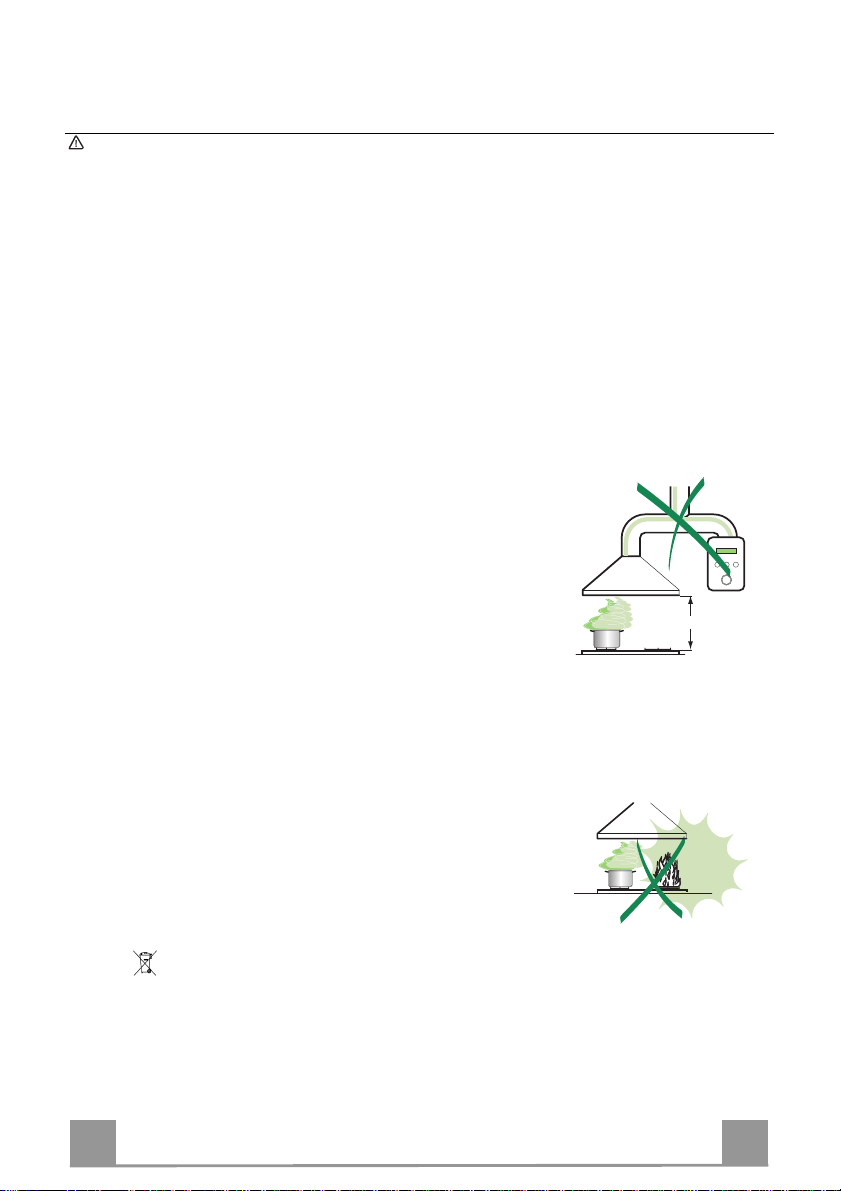
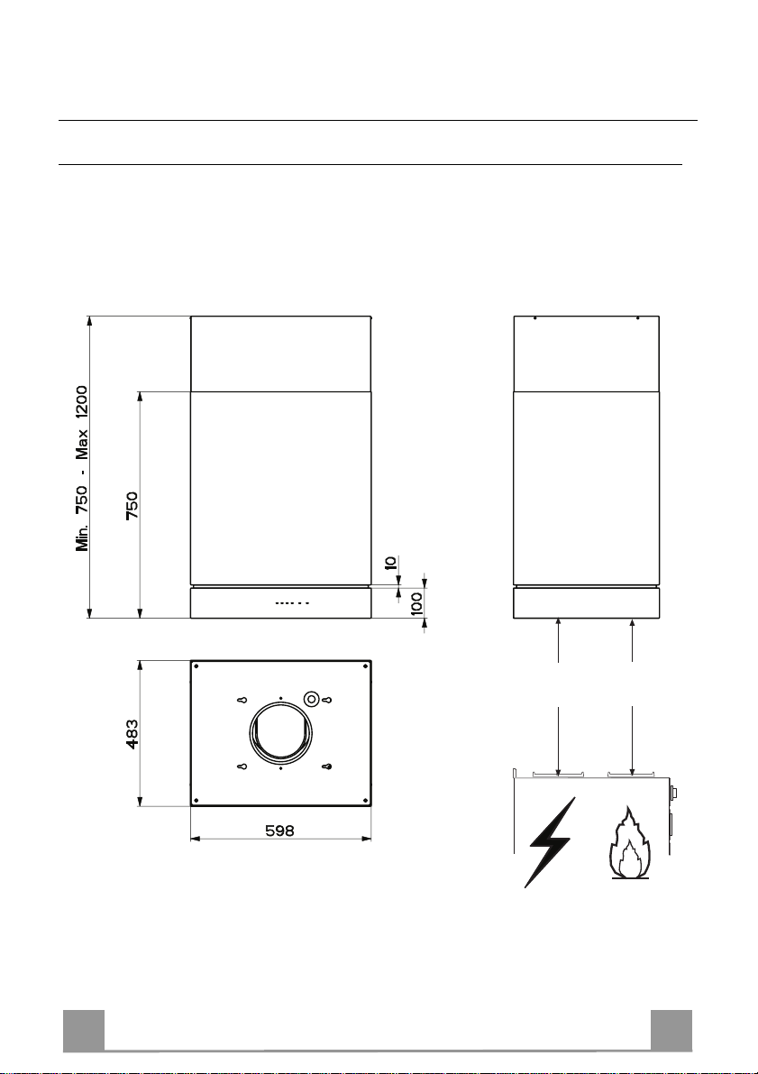
• The minimum safety distance between the cooker top and the extractor hood
is 650 mm (some models can be installed at a lower height, please refer to the
paragraphs on working dimensions and installation).
• Check that the mains voltage corresponds to that indicated on the rating plate
fixed to the inside of the ho od.
• For Class I appliances, check that the domestic power supply guarantees adequate earthing.
Connect the extractor to the exhaust flue through a pipe of minimum diameter
120 mm. The route of the flue must be as shor t as possible.
• Do not connect the extractor hood to exhaust ducts carrying combustion fumes
(boilers, fi replaces, etc.).
• If the extractor is used in conjunction with non-electrical appliances (e.g. gas
burning appliances), a sufficient degree of aeration must be guaranteed in the
room in order to prevent the backflow of exhaust gas. The kitchen must have
an opening communicating directly with the open air in order to guarantee the
entry of clea n air.
USE
• The extractor hood has been designed exclusively for domestic use to eliminate kitchen smells.
• Never use the hood f or purposes ot her than for which it has ben designed.
• Never leave high naked flames under the hood when it is in operation.
• Adjust the flame intensity to direct it onto the bottom of the pan only, making
sure that it does not engulf the sides.
• Deep fat fryers must be continuously monitored during use: overheated oil can
burst into flames.
• Do not flambè under the range hood; risk of fire
• This appliance is not intended for use by persons (including children) with reduced physical, sensory or mental capabilities, or lack of experience and
knowledge, unless they have been given supervision or instruction concerning
use of the appliance by a per son responsible for thei r safety.
• Children should be supervised to ensure that they do not play with the appliance.
MAINTENANCE
• Switch off or unplug the appliance from the mains supply before carrying out
any maintenance work.
• Clean and/or replace the Filter s after the specified time period (Fire hazard)
• Clean the hood using a damp cloth and a neutral liquid detergent.
The symbol on the pro duct or on its pack aging in dicates th at this pr oduct m ay not be
treated as hous e hold was te. Ins tea d it s hal l b e ha nde d ov er t o t he a ppli ca ble col lec ti on p oi nt
for the recycl ing of elec trical and electr onic equ ipment. B y ensuri ng this pr oduct i s dispose d
of correctly, you will help prevent potential negative consequences for the environment and
human healt h, which could otherwi se be caused by inappr opriate waste handli ng of this
product. For m ore detailed inf ormation about r ecycling of this pr oduct, please c ontact your
local city offic e, y our ho use hol d was te di spos al serv ic e or the s hop wher e y ou pur chas ed t h e
product.
3
3
Page 4

EN
CHARACTERISTICS
Dimensions
Min.
650mm
Min.
650mm
4
4
Page 5
EN
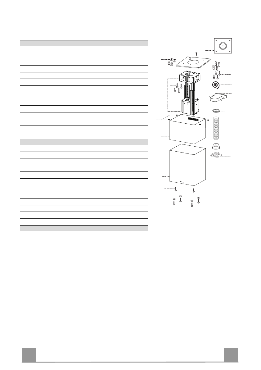
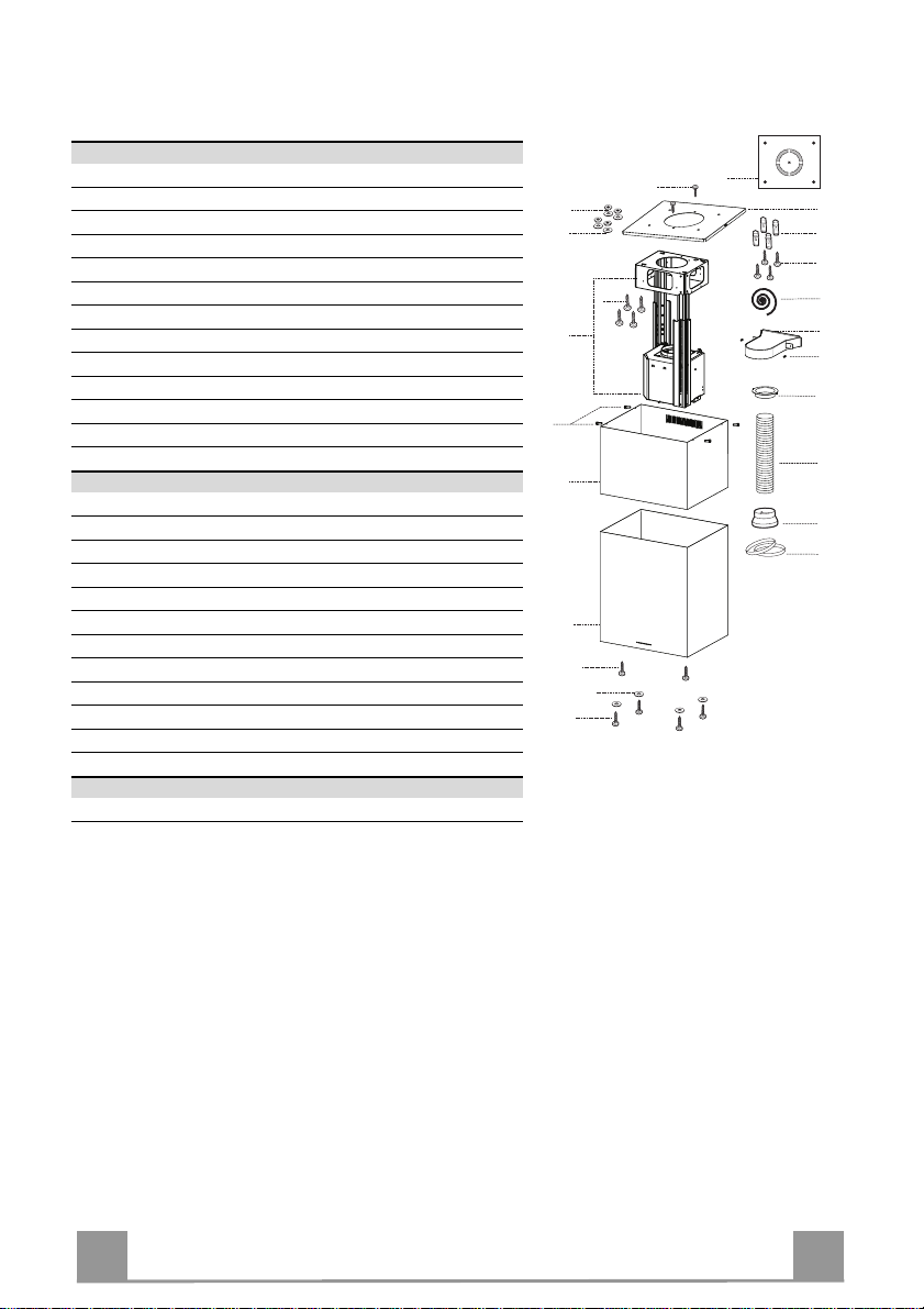
Components
Ref. Q.ty Product Components
1 1 Hood Body, complete with: Controls, Light, Blower,
Filters
2 1 Upper Chimney
7.1 1 Telescopic f rame complete with extractor, consisting of:
7.1a 1 Upper frame
7.1b 1 Lower frame
9 1 Reducer Flange ø 150-120 mm
13 1 Gasket
14 1 Hood Body Air Out let Extension Piece
15 1 Air Outlet Connection
25 Pipe clamps (not included)
26 1 Fixing Part of the upper Chimney
29 1 Air outlet connection tube
Ref. Q.ty Installation Components
11 4 Wall Plugs ø 10
12c 4 Screws 2,9 x 9, 5
12f 2 Screws M6 x 15
12g 4 Screws M6 x 80
12h 4 Screws 5,2 x 70
12q 4 Screws 3,5 x 9,5
12w 2 Screws M3 x 8
21 1 Drilling template
22 8 6.4 mm int. dia washers
23 4 M6 nuts
24 2 Fixing knobs f or the air outlet connect ion piece
Q.ty Documentation
1 Instruction Manual
12w
23
22
7.1a
12g
7.1
7.1b
12c
2
1
12f
22
12q
21
26
11
12h
13
15
24
14
29
9
25
5
5
Page 6

EN
INSTALLATION
Drilling the Ceiling/shelf and fixing the frame
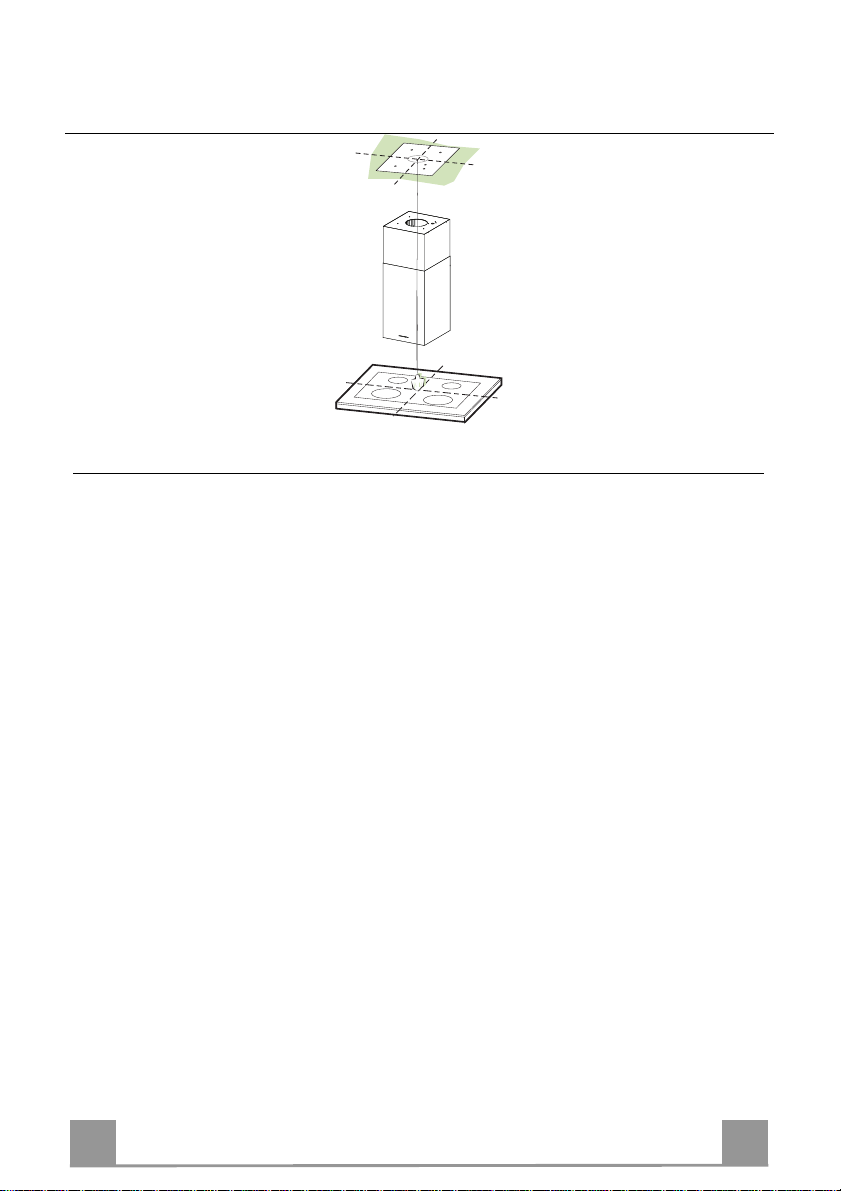
DRILLING THE CEILING/SHELF
• Use a plumb line to mark the centre of the hob on the ceiling/support shelf.
• Place the drilling template 21 provided on the ceiling/support shelf, making sure that the
template is in the correct position by lining up the axes of the template with those of the hob.
• Mark the centres of the holes in the template.
• Drill the holes at the points marked:
• For concrete ceilings, drill for plugs appropriate to the screw size.
• For hollow brick ceilings with wall thickness of 20 mm: drill ø 10 mm(immediately insert
the Dowels 11 supplied).
• For wooden beam ceilings, drill according to the wood screws used.
• For wooden shelf, drill ø 7 mm.
• For the power supply cable feed, drill ø 10 mm.
• For the air outlet (Ducted Versio n), drill according to t he diameter of the external air exhaust duct connection.
• Insert two screws of the following type, crossing them and leaving 4-5 mm from the ceiling:
• For concrete ceilings, use the appropriate plugs for the screw size (not provided).
• for Cavity ceiling with inner space, with wall thickness of approx. 20 mm, Screws 12h,
supplied.
• For wooden beam ceilings, use 4 wood screws (not provided).
• For wooden shelf, use 4 screws 12g with washers 22 and nuts 23, provided.
6
6
Page 7

EN
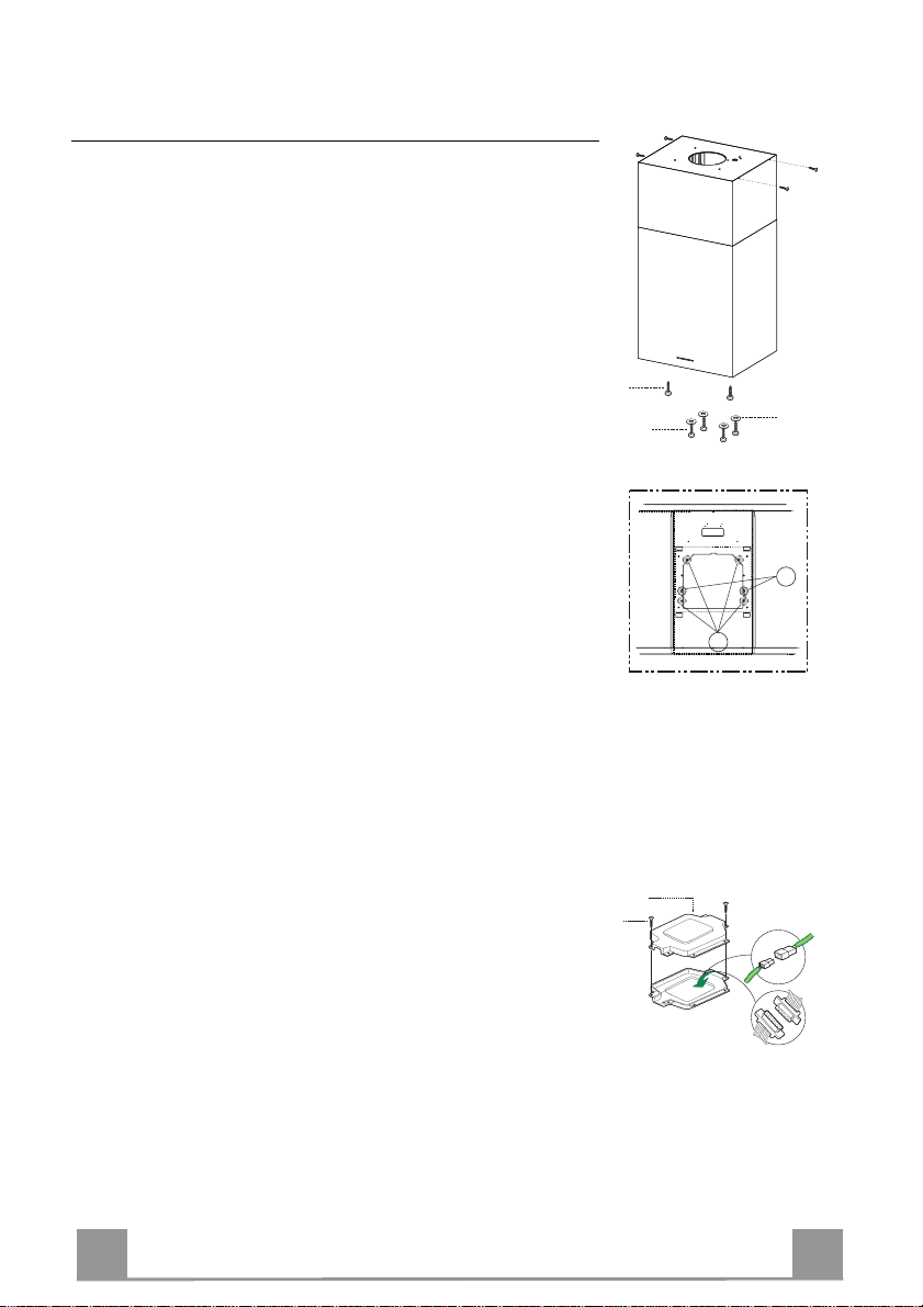
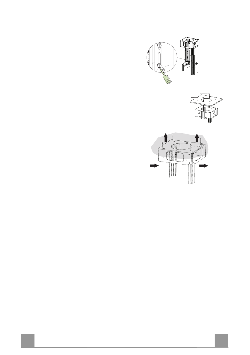
FIXING THE FRAME
If you wish to adjust the height of the frame, pro ceed
as follows:
• Unfasten the metric screws joining the two columns,
located at the sides of the frame.
• Adjust the frame to the required, then replace all the
screws removed as above.
• Fix the Fixing Part of the Upper Chimney 26 to the
hanging kit using the 2 screws 12w (M3 x 8).
• Lift up the frame, fit the frame slots onto the screws
up to the slot end positions.
• Tighten the two screws and fasten the other two
screws provided; before locking the screws com-
pletely, it is possible to adjust the frame by turning it,
making sure that the screws do not come out of their
housing in the adjustment slot.
• It is no w possible to place and tighten the 4 safet y
screws, Proceed as follows:
• drill the ceiling with a 10 mm ø bit taking as refer-
ence the holes of the side parts of the upper
chimney fixing part.
• insert the 4 dowels (provided).
• insert the washers (provided) to the screws and
tighten the screws
• The Frame must be securely fasten ed so as to sup port
both the weight of the Hood and the stress caused by
occasional axial pressure against the fitted Appliance. After fixing, make sure that the base is stable
even when the Frame is subjected to lateral stress.
• If the Ceiling is not strong enough in the area where
the hood is to be fixed, the Installer must strengthen
the area using suitable plates and counterplates anchored to resistant structures.
12w
26
1
2
1
2
7
7
Page 8
EN
9
ø 150
ø 120
25
25
14
15
24
15
14
15
9
29
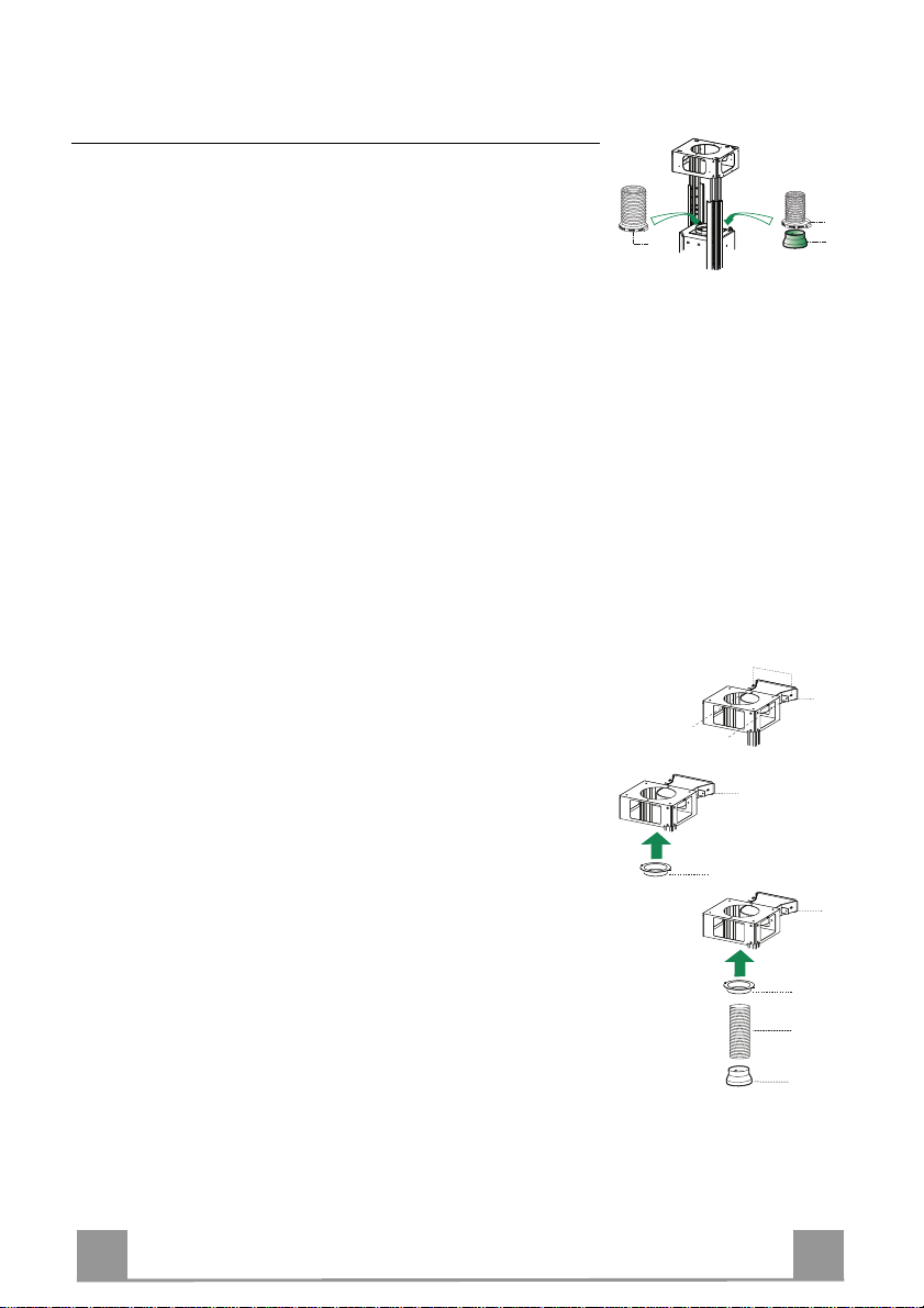
Ducted version air exhaust system Connection
When installing the ducted version, connect the hood to the
chimney using either a flexible or rigid pipe ø 150 or 120 mm,
the choice of which is left to the installer.
• To install a ø 120 mm air exhaust connection, insert the reducer flange 9 on the hood body outlet.
• Fix the pipe using the pipe clamps 25 (not provided).
• Remove any activated charco al filters.
RECIRCULATION VERSION AIR OUTLET
• Insert the reducer flange 9 on th e air o utlet of the extractor.
• Attach the ad hesive Novastik gasket 13 to the air outlet connection 15 and fix this to the upper frame using the 2 knobs 24.
• Fix the air outlet con nect ion exten sio n p iece 14 to the air outlet
connection 15.
• Place the air outlet connect ion tube 29 between th e two air o ut lets.
8
8
Page 9
EN
A
B
12c
22
12f
12q
ELECTRICAL CONNECTIO
N
24
12e
Cmd
Lux
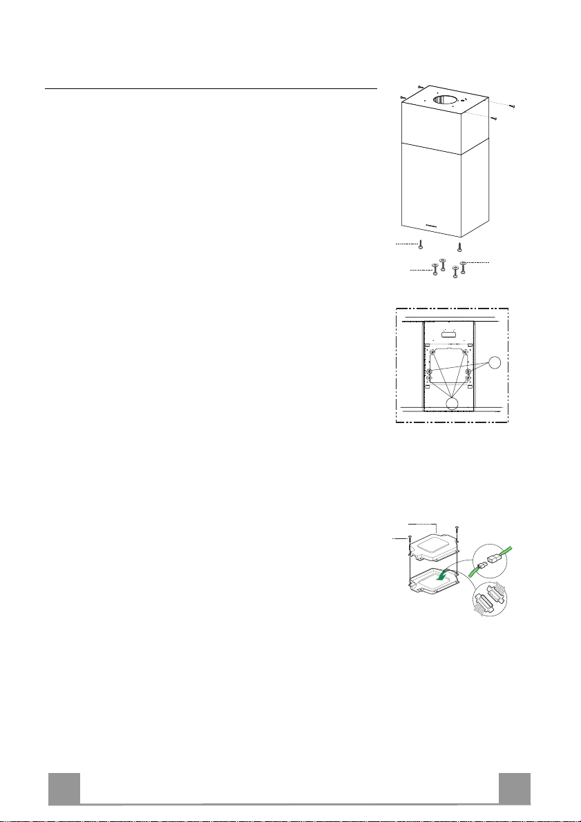
Flue assembly - Mounting the hood body
• Insert the upper duct and fix it on the top of the upper duct
connection using the 12c screws (2.9 x 9.5) supplied with the
appliance.
Recirculation version
• It is necessary to make sure that the air o utlet conn ection 15 is
placed correctly so that the ai r outlet grid in it corresponds to
that of the chimney.
• If the grids of the two parts are not corresponding to each
other, it will be necessary to remove the chimney and to adjust
the position of the air outlet connection 15, and at last to assembly the parts again by following the earlier indications.
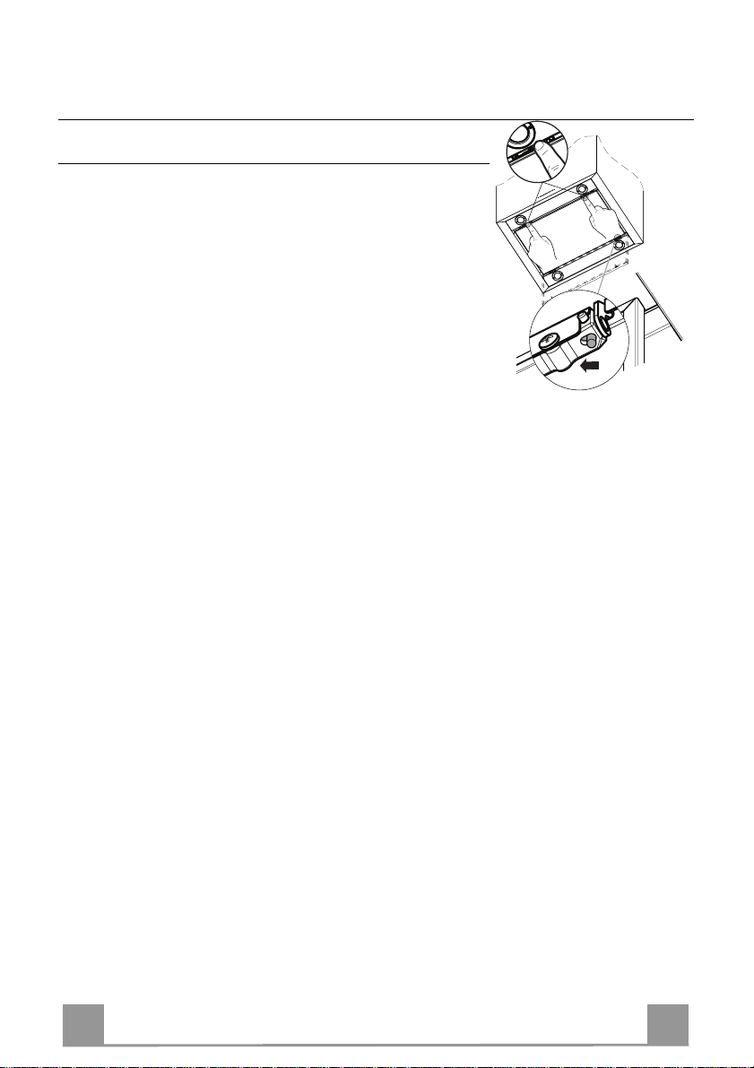
Before fixing the hood body to the frame:
• Screw the 2 screws 12f half way into the holes provided in the
sides of the bottom of the frame.
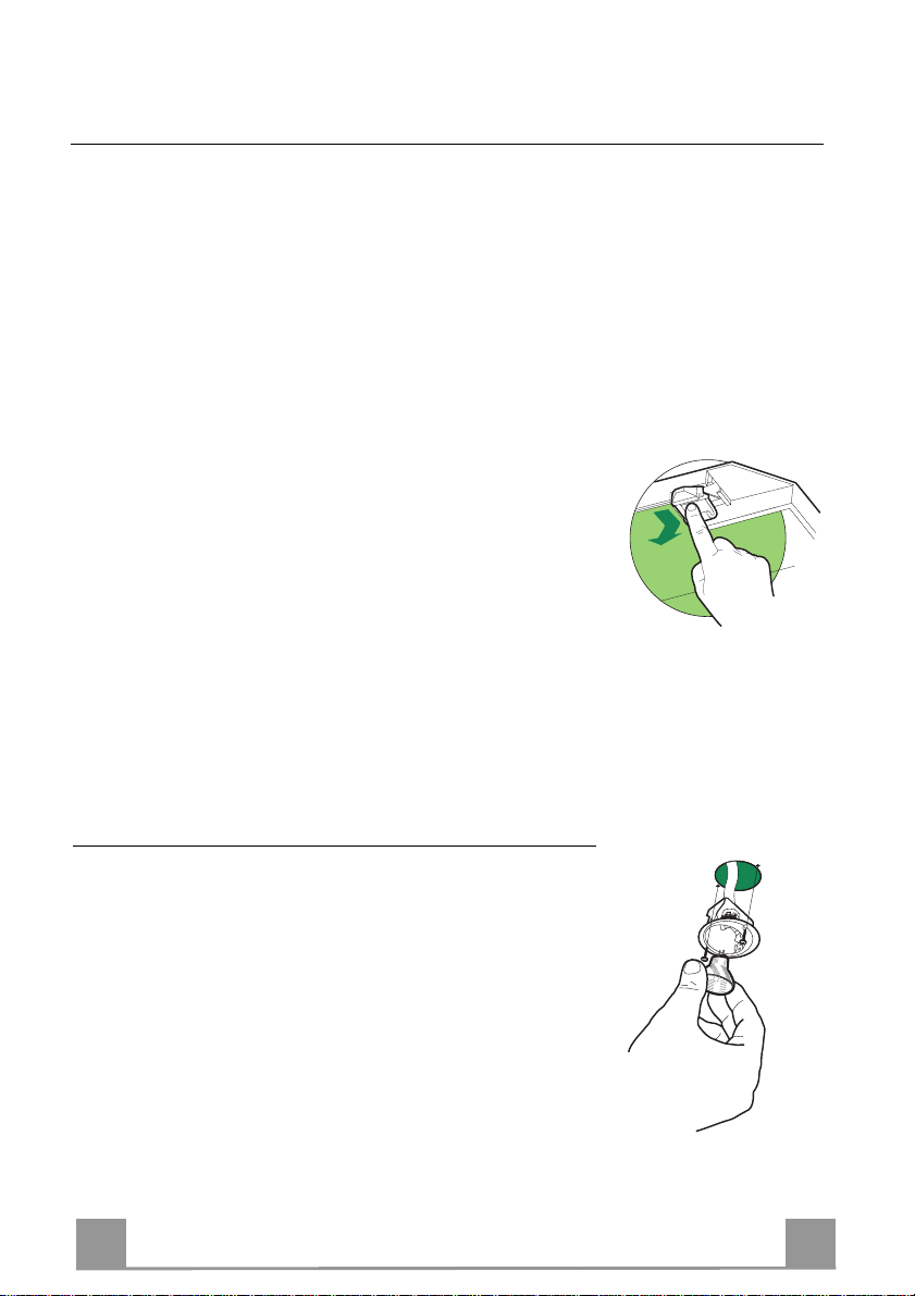
• Open the suction panel by turning the specific knob.
• Disconnect the panel from the hood canopy by sliding the fixing pin lever.
• Remove the grease filters from the hood body.
• Remove any activated charco al filters.
• Lift the hood canopy and engage the screws 12f in the slots (A)
as far as they will go.
• Working from below, fix the hood canopy to the frame (B),
using the 4 screws 12q and 4 washers 22 provided, then tighten
all the screws securely.
• Connect the Hood to the mains power supply, inserting a twopole cut-out switch with contact aperture of at least 3 mm
along the line.
• Pull the Comfort Panel to open it, ensure that the supply cable
connector is properly insert ed into the Suction device socket
• Join the connector s.
• P lace the connectors in the junction box 24 and close it using
the 2 screws 12e (2,9 x 9,5) provided.
• Install the odour filter and the charcoal filter in case the hood is
to be used in recycling version.
• Install the grease filter again, and successively the suction
panel.
9
9
Page 10
EN 110
USE
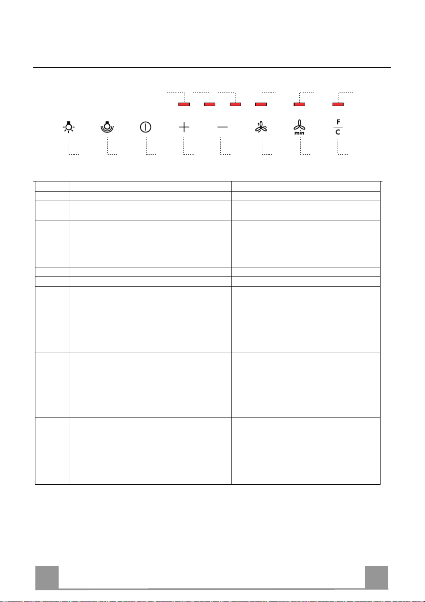
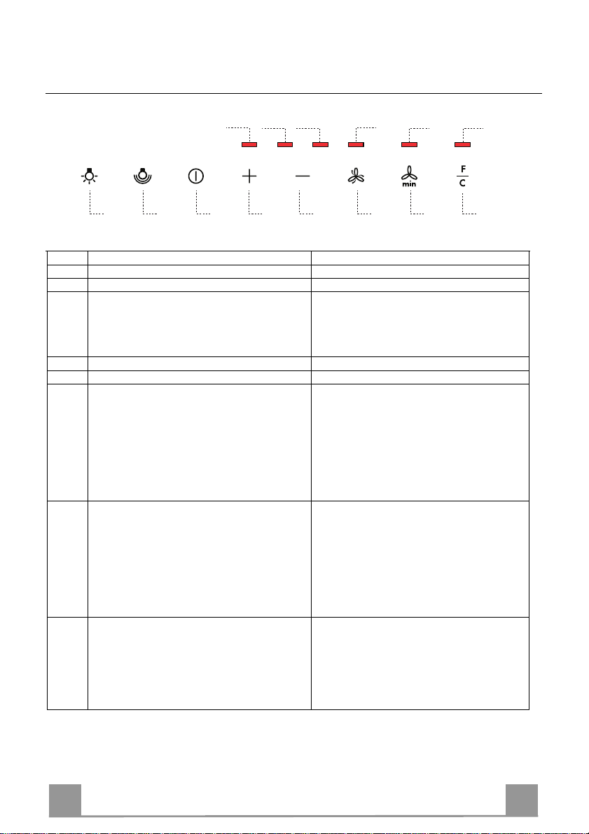
A B C D E F G H
Button Function LED
Turns the ligh ting system on and off. -
A
Turns the reduced intensity lighting system on
B
and off.
Turns the suction motor on and off at the last
C
speed used.
Increase the working speed. -
D
Decrease the working sp eed. -
E
Activates intensive speed from any other speed
F
or with the motor off. This speed is timed to
run for 5 minutes, after which the system returns to the previous speed. Suitable t o deal
with maximum cooki ng fumes.
Disabled by pr essing the Button or turning the
Motor off.
Activates automatic delayed shutdown of the
G
Motor and the Lighting System after 10’ if
Speed Three i s set, after 1 5’ if Speed Two is
set, after 20’ if Speed One is set. Suitable to
complete elimination of residual fumes. Disabled by pressi ng the button or turning the motor off.
Resets the Filter saturation ala r m, if indicated. After 100 Working Hours, Led H lights up
H
Led V1 V2 V3
Control panel
-
The LEDs turn on and off according to th e
speed set.
Speed 1, Led V1 on.
Speed 2, Led V1+V2 on.
Speed 3, Led V1+V2+V3 on.
Led F lights up.
Led G lights up .
Fixed to indicate saturation of the Metal
Grease filters
After 200 Working Hours, Led H flashes to
indicate saturation of the Activated Charcoal Filters.
F G H
Warning: In order to activate the function press on the s ymbol
Page 11
EN 111
MAINTENANCE
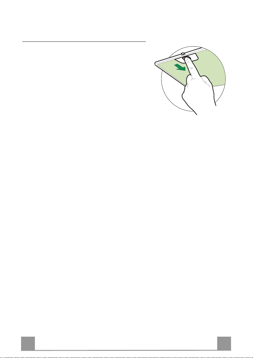
Cleaning the Comfort Panels
• Pull the Comfort Panel to open it.
• Disconnect the panel from the hood canopy by sliding the fixing pin lever.
• The comfort panel must never be washed in a dishwasher.
• Clean the outside by using a damp cloth and neutral liquid detergent.
• Clean the inside as well by using a damp cloth and neutral detergent; do not use wet cloths or sponges, or jets of water; do
not use abrasive substances.
• When the above operation has been completed, hook the panel
back to the hood canopy and close it by turning the knob in the
opposite direction.
Page 12
EN 112
Metal grease filters
CLEANING THE SELF-BEARING METAL GREASE FIL-
TERS
Resetting the alarm signal
• Turn the Lights and the Suction Motor off.
• Press button H.
Cleaning the Filters
• These can be washed in the dishwasher, and need to
be cleaned whenever the H Led comes on or at least
once every 2 months use, or more frequently if use is
particularly intensive.
• Pull the comfort panels to open them.
• Remove the filters one by one pushing them towards
the back side of the hood unit and simultaneously
pulling downwards.
• Any kind of bending of the filters has to be avoided
when washing them. Before fitting them again into
the hood make sure that they are completely dry.
(The colour of the filter surface may change throughout the time but this has no influence to the filter efficiency).
• When fitting the filters into the hood pay attention
that they are mounted in correct position the handle
facing outwards.
• Close the comfort panel.
Page 13
EN 113
Activated Charcoal Filter (Recirculation Version)
This cannot be washed or regenerated, and must be changed at least once every 4 months, or
when led H starts to flash. The alarm signal only appears when the Suction motor is turned on.
Activating the alarm signal
• In Recirculation Version Hoods, the Filter Saturation Alarm must be activated on installation or at a later date.
• Turn the Lights and the Suction Motor off.
• Press button G.
• Within 5 seconds, press Button H until Led H flashes in confirmation:
• Led flashes twice – Activated Charcoal Filter saturation alarm ACTIVATED.
• Led flashes once – Activated Charcoal Filter saturation alarm DEACTIVATED.
Changing the Activated Charcoal Filter
Resetting the alarm signal
• Turn the Lights and the Suction Motor off.
• Press button H.
Changing the Filter
• Open the comfort panels pulling them downwards.
• Remove the metal grease filters.
• Remove the saturated charcoal filter by releasing the fixing
hooks
• Fit the new filter and fasten it in its correct position.
• Put the metal grease filters in their seats.
• Close the comfort panels.
Lighting
LIGHT REPLACEMENT
20 W halogen light.
• Remove the 2 screws fixing the Lighting support, and pull it
out of from the Hood.
• Extract the lamp from the Support.
• Replace with another of the same type, making sure that the
two pins are properly inserted in the lamp holder socket holes.
• Refit the Support, fixing it in place with the two screws removed as above.
Page 14

FR 114
650 mm min.
CONSEILS ET SUGGESTIONS
La présente notice d'emploi vaut pour plusieurs versions de l'appareil. Elle peut
contenir des descri ptions d'accessoires ne figura nt pas dans votre app ar eil.
INSTALLATION
• Le fabricant déc line toute respons abilité en cas de dommage dû à une insta llation
non correcte ou non conforme aux règl es de l’art.
• La distance minimale de sécurité entre le plan de cuisson et la hotte doit être de
650 mm au moins (certains modèles peuvent être installés à une hauteur inférieure : se reporter aux paragraphes « Encombreme nt » et « Installation »).
• Vérifier que la tension du secteur correspond à la valeur qui figure sur la plaquette
apposée à l’intérieur de la hotte.
• Pour les Appareils appartenant à la Ière Cla sse, veiller à ce que la mise à la terre
de l’installation électrique domestique ait été effectuée conformément aux normes
en vigueur.
• Connecter la hotte à la sortie d’air aspiré à l’aide d’une tuyauterie d’un diamètre
égal ou supérieur à 120 mm. Le parcours de la tuyauterie doit être le plus court
possible.
• Eviter de connecter la hotte à des conduites d’évacuation de fumées issues d’une
combustion tel que (Chaudière, cheminée, etc…).
• Si vou s utilis ez de s app areils qui n e fonc tionnent pas à l’électricité dans la pièce ou
est installée la hotte (par exemple: des appareils fonctionnant au gaz), vous devez
prévoir une aération suffisante du milieu. Si la cuisine en est dépourvue, pratiquez
une ouverture qui communique ave c l’extérieur pour garantir l’infiltration de l’air pur.
UTILISATION
• La hotte a été conçue exclusivement pour l’usage domestique, dans le but
d’éliminer les odeurs de la cuisine.
• Ne jamais utiliser abusivement la hotte.
• Ne pas laisser les flammes libres à fort e intensité quand l a hotte est en service.
• Toujours régler les flammes de manière à éviter toute sortie latérale de ces dernières par rapport au fond des marmites.
• Contrôler les friteuses lors de l’utilisation car l’huile surchauffée pourrait
s’enflammer.
• Ne pas préparer d’aliments flambés sous la hotte de cuisine : risque d’incendie
• Cet a pp a reil n e doit pas être utilisé pa r de s pe rso nn es (y co m p ris les en fa n ts) a yant
des capacités psychiques, sensorielles ou mentales réduites, ni par des personnes
n’ayant pas l’expérience et la connaissance de ce type d’appareils, à moins d'être
sous le contrôle et l a formation de per sonnes responsables de leur sécuri té.
• Les enfants doiven t être surveillés pour s' assurer qu'ils ne jouent pas avec l'a ppareil.
ENTRETIEN
• Avant de procéder à toute opération d’entretien, retirer la hotte en retirant la fiche
ou en actionnant l’interrupteur général.
• Effectuer un entretien scrupuleux et en temps dû des Filtres, à la cadence conseillée (Risque d’incendie).
• Pour le nettoyage des su rfaces de la hotte, il suffit d ’utiliser un ch iffon humide et
détersif liqui de neutre.
Le symbole sur le produit ou son emballage indique que ce produit ne peut être traité comme déchet
ménager. Il doit plutôt être remis au point de ramassage concerné, se chargeant du recyclage du matériel
électrique et électronique. En vous assurant que ce produit est éliminé correctement, vous favorisez la
prévention des conséquences négatives pour l’environnement et la santé humaine qui, sinon, seraient le
résultat d’un traitement inapproprié des déchets de ce produit. Pour obtenir plus de détails sur le recyclage
de ce produit, veuillez prendre contact avec le bureau municipal de votre région, votre service d’élimination
des déchets ménagers ou le magasin où vous avez achet é l e produi t .
Page 15
FR 115
CARACTERISTIQUES
Encombrement
Min.
650mm
Min.
650mm
Page 16
FR 116
Composants
Réf. Q.té Composants de Produit
1 1 Corps Hotte équipé de: Comandes, Lumière, Filtres
2 1 Cheminée Supérieure
7.1 1 Treillis télescopique avec Aspirateur, formé par:
7.1a 1 Treillis supérieur
7.1b 1 Treillis inférieur
9 1 Flasque de Réduction ø 150-1 2 0 mm
13 1 Joint
14 1 Rallonge Sortie Air Corps Hotte
15 1 Raccord Sortie Air
25 Colliers de serrage serre-tube (non compris)
26 1 Fixation de la Cheminée Supérieur
29 1 Tuyau Raccord Sortie de l’Air
Réf. Q.té Composants pour l’installation
11 4 Chevilles ø 10
12c 4 Vis 2,9 x 9,5
12f 2 Vis M6 x 15
12g 4 Vis M6 x 80
12h 4 Vis 5,2 x 70
12q 4 Vis 3,5 x 9,5
12w 2 Vis M3 x 8
21 1 Gabarit de perçage
22 8 Rondelles øi 6,4
23 4 Écrous M6
24 2 Pommeaux de fixation Raccord Sortie de l’Air
Q.té Documentation
1 Manuel d’instructions
12w
23
22
7.1a
12g
7.1
7.1b
12c
2
1
12f
22
12q
21
26
11
12h
13
15
24
14
29
9
25
Page 17
FR 117
INSTALLATION
Perçage Plafond/Étagère et Fixation Treillis
PERÇAGE PLAFOND/ETAGERE
• À l’aide d’un Fil à plomb, reporter sur le Plafond/Étagère de support le centre du Plan de
Cuisson.
• Poser contre le Plafond/Étagère le Gabarit de Perçage 21 fourni avec l’appareil, en faisant
coïncider son centre avec le centre projeté et en alignant les axes du Gabari t avec les axes du
Plan de Cuisson.
• Marquer les centres des Trous du Gabarit.
• Percer les trous qui ont été marqu és:
• Plafond en Béton massif: en fonction des Goujons pour Béton utilisés.
• Plafond en Briques avec chambre à air, avec ép aisseur rési stante d e 20 mm: ø 10 mm (in-
sérer immédiatement les Chevilles 11 fournies avec l’appareil).
• Plafond en Poutrage en Bois: en fonction des Vis à Bois utilisées.
• Étagère en Bois: ø 7 mm.
• Passage du Câble électrique d’Alimentation: ø 10 mm.
• Sortie Air (Version Aspirante): en fonction du diamètre de la connexion avec les Tuyaux
d’Évacuation Externe.
• Visser deux vis en les croisant et en laissant 4-5 mm. de distance par rapport au plafond:
• pour le Béton massif, des Goujons pour Béton, non fournis avec l’appareil.
• pour Briq ues percées, ayant une épaisseur résistante de 20 mm. environ, utiliser les Vis
12h, fournies avec l'appareil.
• pour le Poutrage en bois, 4 Vis à bois, non fournies avec l’appareil.
• pour l’Étagère en Bois, 4 Vis 12g avec Rondelles 22 et Écrous 23, fournis avec l’appareil.
Page 18
FR 118
FIXATION DU TREILLIS
Si l’on souhaite régler la hauteur du treillis, effectuer
les opérations suivantes:
• Dévisser les vis métriques qui unissent les deux colonnes, qui se trouvent sur les côtés du treillis.
• Régler la hauteur souhaitée du treillis et revisser les
vis qui ont été précédemmen t retirées.
• Fixer la Fixation de la Cheminée Supérieure 26 au
trellis à l’aide des 2 Vis 12w (M3 x 8).
• Soulever le treillis, encastrer les oeillets sur les vis et
faire coulisser jusqu’à la butée;
• Serrer les deux vis et visser les deux autres vis fournies avec l’appareil; avant de serrer défini-tivement
les vis, il est possible d’effectuer des réglages en
tournant le treillis, en veillant à ce que les vis ne sortent pas du logement de l’oeillet de réglage.
• Maintenant il est possible de visser les 4 vis de sécurité; pour effectuer cette opération, suivre les instructions suivantes :
• percer le plafond,avec une mèche de ø 10, en uti-
lisant les trous qui se trouvent sur les côtés u dispositif de fixation de la cheminée supérieure.
• Insérer les 4 chevilles fournies avec l’appareil.
• Insérer les Rondelles fournies avec l’appareil dans
les vis, puis serrer.
• La fixation du Treillis doit être effectuée de façon
sûre, en fonction du poids de la Hotte et des contraintes provoquées par des poussées latérales occasionnelles de l’Appareil monté. Après avoir effectué la
fixation, vérifier que la base soit stable, même si le
Treillis est soumis à des contraintes de flexion.
• Dans toutes les éventualités selon lesquelles le Plafond ne serait pas suffisamment robuste en correspondance du point de suspension, l’Installateur devra
se charger de le rendre plus solide avec des plaques
et contre-plaques approp riées, ancrées aux parties résistantes, du point de vue structu rel.
12w
26
1
2
1
2
Page 19

FR 119
9
ø 150
ø 120
25
25
14
15
24
15
14
15
9
29
SORTIE AIR VERSION ASPIRANTE
En cas d’installation en version aspirante, brancher la hotte à la
tuyauterie de sortie via un tube rigide ou flexible de ø 150 ou 120
mm, au choix de l’installateur.
• En cas de branchement avec u n tube de ø120 mm, insérer le
flasque de réduction 9 sur la sortie du corps de la hotte.
• Fixer le tuyau à l’aide des Colliers de serrage serre-tube 25 (ne
fournis pas).
• Retirer les éventuels filtres anti-odeur au charbon actif.
SORTIE AIR VERSION FILTRANTE
• Insérer la Flasque de raccord 9 sur la sortie de l’Aspirateur.
• Fixer la Garniture Adhésive Novastik 13 sur le Raccord Sortie
de l’Air 15 et fixer celle-ci au treillis supérieur, au moyen des 2
Pommeaux 24.
• Fixer la Flasque de Raccord Sortie de l’ Air 14 au Raccord S ortie de l’Air 15.
• Conn ecter les deux sorties au Tuyau Raccord Sortie de l’Air
29.
Page 20
FR 220
A
B
12c
22
12f
12q
24
12e
Cmd
Lux
Montage de la Cheminée et Fixation du Corps de la Hotte
• Enfiler le conduit supérieur dans la partie supérieure du raccord du
conduit supé rieur et l e fixer a u moyen des vis 12c (2,9 x 9 ,5) fournies avec l’appareil.
Version Filtrante
• S’assurer que le Raccord Sortie de l’Air 15 se trouve en correspondance de la Grille de la Cheminée.
• Si tel n’est pas le cas, retirer la cheminée et ajuster la position du
Raccord Sortie de l’Air 15; ensuite, remonter les pièces comme décrit précédemmen t.
Avant de fixer le Corps de la Hotte au Treillis:
• Visser à mi-course les 2 vis 12f sur la partie inférieure du treillis en
position latérale en correspondance des 2 trous prévus.
• Ouvrir le pannea u aspira nt, en tourna nt le bouton sp écialement p révu.
• Décrocher le panneau du corps de la hotte, en faisant coulisser le levier
du goujon de fixation spécialement prév u.
• Retirer les Filtres anti-graisse du Corps de la Hotte.
• Retirer les éventuels Filtres Anti-odeur au
• Soulever le corps de la hotte et emboîter les vis 12f dans leur trou
(réf.A) jusqu’en bu tée .
• En pass ant pa r dess ous, f ixer avec l es 4 vis 12q et les 4 rondell es 22
fournies le corps de la hotte au treillis prévu (réf.B) et serrer définitivement toutes les vis.
BRANCHEMENT ÉLECTRIQUE
• Brancher la Hotte au Réseau d’Alimentation, en interposant un
Interrupteur bipolaire avec ouverture des contacts de 3 mm. au
moins.
• Ouvrir le Comfort Panel, en tirant ce dernier s’assurer que le
connecteur du Câble d’alimentation soit inséré correctement dans
la prise de l’Aspirateur.
• Effectuer les connexions des connecteurs.
• Ranger les Connecteurs dans la Boîte de protection 24 en la
fermant à l’aide des 2 Vis 12e (2,9 x 9,5) fournies avec
l’appareil.
• Pour la Version Filtrante, monter le Filtre Anti-odeur aux Charbons actifs.
• Remonter les filtres Anti-graisse puis, par la suite, le panneau aspirant.
Page 21
FR 221
UTILISATION
Led V1 V2 V3
A B C D E F G H
Tableau de commandes
Touche Fonction Voyant
Allume et éteint l’éclairage. -
A
Allume et éteint l’éclaira g e à intensité réd uite. -
B
Allume et étein t le moteur d’aspi ration à la
C
dernière vitesse utilisée.
Augmente la vitesse de fonctionnement. -
D
Réduit la vitesse de fonctionnement. -
E
Active la fonction de vitesse intensive à partir
F
de n’importe quelle autre vitesse ou à moteur
éteint ; la vitesse est maintenue pendant 5 minutes : à la fin de ce délai, le système retourne
à la vitesse de réglage précédente. Approprié
pour faire face aux plus grosses émissions de
fumées de cuisson.
Pour désactiver, appuyer sur la touche ou
éteindre le m o teur.
Active la fonction d’extinction automatique
G
temporisée du moteur et de l’éclairage pendant
10 min si la vitesse de réglage est la troisième,
pendant 15 min si la vitesse de réglag e est la
deuxième, et pendant 20 min si la vitesse de
réglage est la première. Appr opriée pour compléter l’élimination des odeurs résiduelles ,
cette fonction est désactivée en appuyant sur la
touche ou en éteignant le moteur.
Exécute la rem ise à zéro de l’alar me de satura-
H
tion des filtres seulement sur signalisation.
F G H
Les voyants s’allument et s’éteignent à la vitesse de réglage.
Vitesse 1, voyant V1 allumé.
Vitesse 2, voyants V1 + V2 allumés.
Vitesse 3, voyants V1 + V2 + V3 allumés.
Le voyant F s’allume.
Le voyant G s’allume.
Au bout de 100 heures de fonctionnement, le
voyant H est allumé sans clignoter de sorte à
signaliser la saturation des filtres métalliques.
Au bout de 200 heures de fonctionnement, le
voyant H clignote, signalant ainsi la saturation des filtres au charbon actif.
Attention: pour activer la presse sur le symbole
Page 22

FR 222
ENTRETIEN
Nettoyage des Confort Panel
• Ouvrir le Confort Panel, en tirant ce dernier.
• Décrocher le panneau du corps de la hotte, en faisant coulisser
le levier du goujon de fixation spécialement prévu.
• En aucun cas, le confort panel ne doit être lavé au lavevaisselle.
• Le nettoyer à l’extérieur à l’aide d’un chiffon humide et d’un
détergent liquide neutre.
• Le nettoyer également à l’intérieur, en utilisant un chiffon humide et un détergent neutre; ne pas utiliser des chiffons ou des
éponges mouillées, ni des jets d’eau; ne pas utiliser des substances abrasives.
• Lorsque l‘op ération est achevée, accrocher à nouveau le panneau sur le corps de la hotte, puis le refermer, en tournant le
bouton dans le sens inverse par rapport à l’ouverture.
Page 23

FR 223
Filtres à graisse métalliques
NETTOYAGE DES FILTRES À GRAISSE MÉTALLIQUES
AUTOPORTANTS
Acquittement du signal d’alarme
• Éteindre les lumières et le moteur d’aspiration.
• Enfoncer la touche H.
Nettoyage des filtres
• Les filtres sont lavables même en lave-vaisselle et
doivent être lavés chaque fois que le voyant H
s’allume ou au moins tous les 2 mois, voire plus souvent en cas d’utilisation particulièrement intensive.
• Tirer sur les panneaux confort pour les ouvrir.
• Retirer les filtres, un à un, en les poussant vers la
partie postérieure du groupe tout en tirant vers le bas.
• Laver les filtres en évitant de les plier, et les faire
sécher avant de les remonter. (Tout changement de
couleur sur la surface du filtre, susceptible de se
produire avec le temps, ne nui t en rien à l’efficacité
de ce dernier.)
• Remonter les filtres en faisant attention de tenir la
poignée vers la partie externe visible.
• Refermer les panneaux confort.
Page 24

FR 224
Filtres au charbon actif contre les odeurs (version filtrante)
Ces filtres ne peuvent pas être lavés ou régénérés et ils d oivent être re mplacés q uand le voyant
H clignote, ou au moins tous les 4 mois. L’alarme n’est signalisée que lorsque le moteur
d’aspiration est actionné.
Activation du signal d’alar me
• Dans les hottes en version filtrante, la fonction de signalisation de l’alarme de saturation des
filtres est activée à l’installation ou par la suite.
• Éteindre les lumières et le moteur d’aspiration.
• Enfoncer la touche G.
• Dans les 5 secondes qui suivent, enfoncer la touche H jusqu’à ce que le voyant H commence à clignoter.
• 2 clignotements du voyant – alarme de saturation du filtre au charbon actif contre les
odeurs ACTIVÉE.
• 1 clignotement du voyant – alarme de saturation du filtre au charbon actif contre les
odeurs DÉSACTIVÉE.
Remplacement du filtre anti-odeur au charbon actif
Acquittement du signal d’alarme
• Éteindre les lumières et le moteur d’aspiration.
• Enfoncer la touche H.
Remplacement du filtre
• Tirer sur les panneaux confort pour les ouvrir.
• Retirer les filtres à graisse métalliques.
• Retirer le filtre anti-odeur au charbon actif saturé en agissant
sur les crochets qui le tiennent en place.
• Mettre le nouveau filtre en l’accrochant bien en place.
• Remonter les filtres à graisse métalliques.
• Refermer les panneaux confort.
Eclairage
REMPLACEMENT LAMPES
Lampe halogène de 20 W.
• Retirer les 2 Vis qui fixent le Support éclairage et ôter ce d ernier de la Hotte.
• Extraire la Lampe du Support.
• Re mplacer par un e nouvelle lampe possédant les mêmes caractéristiques, en veillant à ce que les deux fiches soient correctement insérées dans le logement de la Douille.
• Remonter le Support en le fixant à l’aide des deux Vis précédemment retirées.
Page 25

DE 225
650 mm min.
EMPFEHLUNGEN UND HINWEISE
Diese Gebrauchsanleitung gi lt für mehrere G er äte-Ausführungen.
Es ist möglich, dass einzelne Ausstattungsmerkmale beschrieben sind, die nicht auf
Ihr Gerät zutreffen.
FÜR DEN KÜCHENMÖBEL-MONTEUR
• Der Hersteller haftet nicht für Schäden, die auf eine fehlerhafte und unsachgemäße
Montage zurückzuführen sind.
• Der minimale Sicherheitsabstand zwischen Kochmulde und Haube muss 650 mm
betragen (einige Mode lle können an einer ger ingeren Höhe installiert we rden, beziehen Sie sich daz u auf den Absatz Raumbedarf und Installation).
• Prüfen, ob die Netzspannung mit dem Wert auf dem im Haubeninneren angebrachten Schild überei nst immt.
• Das Abluftrohr der Haube muss bei Abluftbetrieb einen Durchmesser von Mindestens 120 mm aufwei sen. Die Abluftst r ecke muss so kurz wie möglich sein.
• Die Haube darf nicht in einen Rauch- oder Abgass chornstein eingeleitet werden.
• Der gemeinsame gefahrlose Betrieb von kamingebundenen Geräten und Dunstabzugshauben ist nur gewährleistet, wenn Raum und/oder Wohnung durch eine geeignete Zuluftöf fnung von ca. 500-600 cm
FÜR DEN BENUTZER
• Die Dunstabzugshaube ist ausschließlich zum Einsatz im privaten Haushalt und zur
Beseitigung von Küchengerüchen vorgesehen.
• Unsachgemäßer Einsatz der Hau be ist zu unterlass en.
• Kochstellen müssen bei Betrieb stets abgedeckt sein. Unbedingt zu vermeiden sind
offene Feuerstellen bei Öl-, G as- und Kohleherde n.
• Frittiergeräte müssen während des Gebrauchs stets beaufsichtigt werden: überhitztes Öl kann sich entz ünden.
• Keine flambierten Speisen unt er der Abzugshaube zubereiten: Brandgefahr.
• Dieses Gerät darf nicht von Personen, auch Kindern, mit ver m inderten psychischen,
sensorischen und geistigern Fähigkeiten, oder von Personen ohne Erfahrung und
Kenntnisse benutzt werden, sofern sie nicht von für ihre Sicherheit verantwortlichen
Personen beaufsichtigt und beim G ebrauch des Gerät s angeleitet werden.
• Kinder dürfen sich nicht unbeaufsichtigt in der Nähe des Geräts aufhalten und auf
keinen Fall mit dem Gerät spielen.
WARTUNG
• Bevor Wartungsarbeiten durchgeführt werden, muss die Stromzufuhr zur Haube
unterbrochen werden, indem der Stecker gezogen oder der Hauptschalter abgeschaltet wird.
• Bei der Filterwartung müssen die vom Hersteller empfohlenen Zeiträume zum Austauschen der Fil t er genauestens eingehalten werde n (Brandgefahr).
• Zur Reinigung der Haubenfläche empfehlen wir ein feuchtes Tuch und mildes
Spülmittel.
2
von außen belüft et sind.
Das Symbol auf dem Produkt oder seiner Verpackung weist darauf hin, dass dieses Produkt
nicht als normaler Haushaltsabfall zu behandeln ist, sondern an einem Sammelpunkt für das Recycling von elektrischen und elektronisc hen Geräten abgegeben werden mus s . Durch Ihren Beitrag zum
korrekten Entsorgen dieses Produkts schützen Sie die Umwelt und die Gesundheit Ihrer Mitmenschen. Umwelt und Gesundheit werden durch falsches Entsorgen gefährdet. Weitere Informationen
über das Recycling dieses Produkts erhalten Sie von Ihrem Rathaus, Ihrer Müllabfuhr oder dem
Geschäft, in dem Sie das Produkt gekauft haben.
Page 26

DE 226
CHARAKTERISTIKEN
Platzbedarf
Min.
650mm
Min.
650mm
Page 27

DE 227
Komponenten
Pos. St. Produktkomponenten
1 1 Haubenkörper mit Schaltern,
2 1 oberer Kamint eil
7.1 1 Teleskopgerüst komplett mit Gebläse, bestehend aus :
7.1a 1 oberer Gerüstteil
7.1b 1 unterer Gerüstteil
9 1 Reduzierflansch ø 150-12 0 mm
13 1 Dichtung
14 1 Verlängerungsstückf. Luftaustrit t Haubenkörper
15 1 Luftaustritt-Anschlussstück
25 Rohrschellen (nicht enthalten)
26 1 Berkaminanschluss
29 1 Anschlussrohr Luftaustritt
Pos. St. Montagekomponenten
11 4 Dübel ø 10
12c 4 Schrauben 2,9 x 9,5
12f 2 Schrauben M6 x 15
12g 4 Schrauben M6 x 80
12h 4 Schrauben 5,2 x 70
12q 4 Schra uben 3,5 x 9,5
12w 2 Schrauben M3 x 8
21 1 Bohrschablone
22 8 Unterlegscheiben ø 6,4
23 4 Schraubenmuttern M6
24 2 Kugelgriffe zur Befestigung Anschl uss Luftaustritt
St. Dokumentation
1 Bedienungsanleitung
12w
23
22
7.1a
12g
7.1
7.1b
12c
2
1
12f
22
12q
21
26
11
12h
13
15
24
14
29
9
25
Page 28

DE 228
MONTAGE
Bohren der Decke/Trägerplatte und Montage des Teleskopgerüsts
BOHREN DER DECKE/TRAGERPLATTE
• Mit Hilfe eines Lots den Kochmulden-Mittelpunkt an der Decke oder Trägerplatte ermitteln
und kennzeichnen.
• Die mitgelieferte Bohrschablone 21 so auf die Decke/Trägerplatte legen, dass die S chablonenmitte mit dem gekennzeichneten Mittelpunkt übereinstimmt und die Schablonenseiten
auf die Seiten der Kochmulde ausrichten.
• Die Mitte der Schablonenbohrungen kennzeichnen.
• Die gekennzeichneten Punkte bohren:
• Massivbeton-Decke: je nach verwendeten Beton-Dübeln.
• Decke aus Hohlkammer-Ziegeln mit 20 mm Wandungsstärke: ø 10 mm (sofort die mitge-
lieferten Dübel 11 einfügen).
• Holzbalkendecke: je nach verwendeten Holzschrauben.
• Holz-Trägerplatte: ø 7 mm.
• Durchgang für das Speisekabel: ø 10 mm.
• Luftaustritt (Abluftversion): je nach Durchmesser des Anschlussrohres für die Luftablei-
tung.
• Zwei sich gegenüberliegende Sc hr a ube n festziehen und 4-5 mm Fre ira um z ur De ck e be las se n:
• bei Massiv-Betondecken mit speziellen Betondübeln, die nicht mitgeliefert werden;
• für Hohlkammer-Ziegeln mit ca. 20 mm Wandungsstärke die mitgelieferten Schrauben
12h verwenden;
• bei Holzbalken-Decken mit 4 Holzschrauben, die nicht mitgeliefert werden;
• bei Holz-Trägerplatten mit 4 Schrauben 12g, Unterlegscheiben 22 und Schraubenmuttern
23, die im Lieferumfang enthalten sind.
Page 29

DE 229
MONTAGE DES TELESKOPGERÜSTS
Für eine eventuelle Regulierung der Gerüsthöhe folgendermaßen vorgehen :
• Die Stellschrauben an den Gerüstseiten, die die beiden Säulen vereinen, lösen.
• Die gewünschte Gerüsthöhe einstellen und die zuvor
entnommenen Schraub en wieder festziehen.
• Den anschluss des oberkamins mit den 2 Schrauben
12w (M3 x 8) an die innemstruktur befestigem.
• Das Gerüst heben, die Langlöcher bei den Schrauben
einrasten und bis zum Anschlag laufen lassen;
• Die beiden Schrauben festziehen und die ande-ren
beiden mitgelieferten Schrauben einschrau-ben; bevor die Schrauben definitiv festgezogen werden,
können Einstellungen durchgeführt werden, indem
das Gerüst gedreht wird; hier-bei ist darauf zu achten,
dass die Schrauben nicht aus dem Sitz des EinstellLangloches gleiten.
• Nun können die 4 Sicherheitsschrauben wie nachstehend beschrieben eingeschraubt we r den:
• mit einem Bohrer ø 10 die Decke bohren und
die Bohrungen an den Seiten des oberen Kaminteils verwenden.
• Die 4 beiliegenden Dübel einfügen.
• Die beiliegenden Unterlegscheiben auf die
Schrauben geben und festziehen.
• Wir verweisen auf die Notwendigkeit einer absolut
sicheren Befestigung des Teleskopgerüsts, die sowohl dem Eigengewicht der Haube wie auch dem
seitlichen Druck, der auf das Gerät einwirken kann,
entsprechen muss.Nach erfolgter M ontage ist zu prüfen, ob das Teleskopgerüst auch bei Biegebeanspruchung stabil ist.
• Sollte die Decke am Befestigungspunkt nicht robust
genug sein, muss der Installateur geeignete Platten
und Gegenplatten verwenden, die an strukturell widerstandsfähigen Teilen verankert werden.
12w
26
1
2
1
2
Page 30

DE 330
9
ø 150
ø 120
25
25
14
15
24
15
14
15
9
29
Anschluss in Abluftversion
Bei Abluftbetrieb kann die Haube vom Installateur wahlweise
mittels Rohr oder Schlauch (ø 150 oder 120 mm) an die Außenrohrleitung angeschlossen werden.
• Bei Verwendung eines Anschlussrohres ø 120 den Reduzierflansch 9 am Haubenaustritt anbringen.
• Das Rohr mit den Rohrschellen 25 fixieren (nicht mitgeliefert).
• Eventuell vorhandene Aktivkohlefilter entnehmen.
Anschluss in Umluftversion
• Den Reduzierflansch 9 auf den Gebläseaustritt geben.
• Die Klebedichtung Novas tik 13 am Anschluss Luftaustritt 15 anbrin-
gen und diesen a m ob eren G erü st mi t Hilf e d er 2 Ku gelgr i ff e 24 befes-
tigen.
• Den Anschlussflansch Luftaustritt 14 am Anschluss Luftaustritt 15
anbringen.
• Di e beiden Austritte mit dem Anschlussrohr Luftaustritt 29 verbinden.
Page 31

DE 331
A
B
12c
22
12f
12q
24
12e
Cmd
Lux
Kaminmontage und Montage des Haubenkörpers
• Den oberen Kamin an der Oberseite des oberen Kaminanschlusses einsetzen und mit den mitgelieferten Schrauben 12c
(2,9 x 9,5) befestigen.
Umluftbetrieb
• Kontrollieren, dass der Anschluss Luftaustritt 15 in Übereinstimmung mit dem Kamingitter positioniert ist.
• Ist dies nicht der Fall, den Kamin entfernen und die Position des
Anschlusses Luftaustritt 15 korrigieren; die Einzelteile wie zu vor
beschrieben wieder montieren.
Vor der Montage des Haubenkörpers am Teleskopgerüst:
• Die beiden Schrauben 12f halb in die beiden vorbereiteten Löcher seitlich am unteren Gitterabschnitt einschrauben.
• Den Saugpaneel durch Drehen des entsprechenden Drehknopfes öffnen.
• Die Fettfilter entnehmen.
• Eventuell vorhandene Aktivkohle-Geruchsfilter entnehmen.
• Den Haubenkörper anheben, die Schrauben 12f bis zum Anschlag in die Langlöcher (Bez. A) stecken.
• Den Haubenkörper mit den mitgelieferten 4 Schrauben 12q
und 4 Unterlegscheiben 22 von unten am vorbereiteten Gitter
(Bez.B) befestigen und alle Schrauben endgültig festschrauben.
ELEKTROANSCHLUSS
• Bei Anschluss der Haube an das Stromnetz muss ein zweipoliger
Schalter mit einem Öffnungsweg von mindestens 3mm zwischengeschaltet werden.
• Den Comfort Panel durch Ziehen öffnen, kontrollieren, dass der
Verbinder des Speisekabels korrekt in die Steckdose des Gebläses
eingesteckt ist.
• Die Anschlüsse der Verbinder vornehmen.
• Den Verbinder wieder in die Verbindungsdose 24 stecken und die-
se mit den 2 mitgeliefert en Schrau-ben 12e (2,9 x 9,5) verschließen.
• Für die Umluftversion den Aktivkohle-Ge ruchsfilter m ontiere n.
• Die Fettfilter und danach den Saugpaneel wieder montieren.
Page 32

DE 332
BEDIENUNG
Led V1 V2 V3
A B C D E F G H
Schalttafel
Taste Funktion LED
Schaltet die Beleuchtung ein oder aus. -
A
Schaltet die verminderte Beleucht ung ein oder
B
aus.
Schaltet den Motor der Absauganlage bei der
C
zuletzt verwendeten Geschwindigkeit ein und
aus.
Erhöht die Betriebsgeschwindigkeit. -
D
Vermindert die Betriebsgeschwindigk e it. -
E
Aktiviert von jeder Geschwindigkeit aus, auch
F
bei abgestelltem Motor, die Intensivgeschwindigkeit, die auf 5 Minuten zeitgeregelt ist.
Nach Ablauf dieser Zeit kehrt das System zu
der zuvor eingestellten Geschwindigkeit zurück. Für die Beseitigung von sehr inten siven
Kochdünsten geeignet.
Wird durch Betätigen der Taste oder Abstellen
des Motors deaktiviert.
Aktiviert bei der dritten Geschwindigkeitsstufe
G
das um 10’, bei der zweiten Stufe das um 15’
und bei der ersten Stufe das um 20’ verzögerte
automatische Abstellen des Motors und der
Beleuchtung. Zur Beseitigung von Restgerüchen geeignet; wird durch Betätigen der Taste
oder Abstellen des Motors deaktiviert.
Fügt ein Reset des Alarms für Filtersättigung
H
aus, sofern diese angezeigt wird.
F G H
-
Die LEDs schalten sich je nach Geschwindigkeitseinstellung ein oder aus.
Gebläsestufe 1, LED V1 an.
Gebläsestufe 2, LED V1 + V2 an.
Gebläsestufe 3, LED V1 + V2 + V3 an.
Die LED F schaltet sich ein.
Die LED G schaltet sich ein.
Nach 100 Betriebsstunden zeigt di e bleibend
eingesch altete LED H die Sättigung der Metallfilter an.
Nach 200 Betrieb sstunden zeigt die blinkende
LED H die Sättigung der Aktivkohlefilter an.
Achtung: auf die Symbol druecken, um das Geraet zu bedien
Page 33

DE 333
WARTUNG
Reinigung der Comfort Panel
• Den Comfort Panel durch Ziehen öffnen.
• Die Platte vom Haubenkörper aushaken, indem der Hebel des
Befestigungsstiftes verschoben wird.
• Die Comfort Panel darf keinesfalls im Geschirrspüler gewaschen werden.
• Außen mit einem feuchten Lappen und neutralem Flüssigreiniger säubern.
• Innen mit einem feuchten Lappen und neutralem Reinigungsmittel säubern; keine nassen Lappen oder Schwämme oder
Wasserstrahl verwenden; kein Scheuermittel verwenden.
• Am Ende die Platte wieder am Haubenkörper einhaken und
schließen, indem der Drehknopf in die dem Öffnen entgegengesetzte Richtung gedreht wird.
Page 34

DE 334
Nun die Filter wieder einbauen, so dass der Griff
Metallfettfilter
REINIGUNG DE R SELBSTTRAGENDE N METALLFETT-
FILTER
Reset des Alarmsignals
• Die Beleuchtung und den Abzugsmotor abstellen.
• Die Taste H drücken.
Reinigung der Filter
• Die Fettfilter sind spülmaschinengeeignet und müs-
sen gewaschen werden, sobald sich die LED H eins-
chaltet, oder mindestens alle 2 Monate, oder auch
öfter, je nach Intensität des Gebrauchs.
• Die Comfort Panels durch Ziehen öffnen.
• Die Filter einzeln ausbauen, indem sie in den hinteren Teil der Gruppe geschoben und gleichzeitig nach
unten gezogen werden.
• Die Filter waschen, ohne sie zu verbiegen, und vor
dem erneuten Einbau trocknen lassen. (die Farbe der
Filteroberfläche kann sich mit der Zeit verändern,
was aber die Wirksamkeit keinesfalls beeinträchtigt.)
•
nach der äußeren Sichtsei t e zeigt.
• Die Comfort Panel wieder schließen.
Page 35

DE 335
Aktivkohle-Geruchsfilter (Filterversion)
Der Aktivkohlefilter ist weder waschbar, noch regenerierbar und muss ausgewechselt werden,
wenn die LED H blinkt, oder mind estens alle 4 Monate . Die Alarmmeldung erfolgt nur, wenn
der Absaugmotor zugesc ha ltet ist.
Aktivierung des Alarmsignals
• Bei den Filterversionen der Abzugshauben wird die Alarmanzeige für Filtersättigung im
Augenblick der Installation oder in der Folge aktiviert.
• Die Beleuchtung und den Absaugmotor abstellen.
• Die Taste G drücken.
• Innerhalb von 5 Sekunden die Taste H drücken, bis die LED H zur Bestätigung blinkt:
• 2 Mal blinken der LED – Alarm wegen Sättigung des Aktivkohlefilters AKTIVIERT.
• 1 Mal blinken der LED – Alarm wegen Sättigung des Aktivkohlefilters DEAKTIVIERT.
Auswechseln des Aktivkohle-Geruchsfilters
Reset des Alarmsignals
• Die Beleuchtung und den Absaugmotor abstellen.
• Die Taste H drücken.
Auswechseln des Filters
• Die Comfort Panel durch Ziehen öffnen.
• Die Fettfilter aus Metall entfernen.
• Den gesättigten Aktivkohle-Geruchsfilter durch Öffnen der
Klammern ausbauen.
• Den neuen Filter in seinen Sitz einhängen.
• Die Fettfilter aus Metall wieder einbauen.
• Die Comfort Panel wieder verschließen.
• Die Kohlefilter können mit dem Hausmüll entsorgt werden.
Beleuchtung
AUSWECHSELN DER LAMPEN
Halogenlampe 20 W
• Vor dem Auswechseln der Lampen, die beiden Schrauben der
Lampenhalterung loesen und die Lampenhalterung aus der
Dunstabzugshaube ziehen.
• Die Lampe aus der Halterung nehmen.
• Die Lampe durch eine gleichwertige ersetzen und bei der Remontage darauf achten, daß die beiden Steckerstifte vorschriftsmäßig in die Lampenfassung eingeführt werden.
• Die Lampenhalterung wieder montieren, indem die beiden zuvor entfernten Schraub en wieder angezogen werden.
Page 36

NL 336
Deze
gebruiksaanwijzing geldt voor verschillende uitvoeringen van het app
a
raat.
650 mm min.
ADVIEZEN EN SUGGESTIES
Het is mogelijk da t er een aantal kenmerken worden beschreven die niet van toepassing zijn op uw a pparaat.
INSTALLATIE
• De fab r ik an t aa nv aardt geen enkele aansprake lijk h e id vo o r schad e d ie vo o r tkom t uit
onjuiste of niet overeenkomstig de r egels der kunst uit gevoerde installaties.
• De minimale veiligheidsafstand tussen de kookplaat en de wasemkap bedraagt 650
mm (sommige modellen kunnen lager worden geïnstalleerd, raadpleeg de paragrafen afmetingen e n installatie).
• Controleer of de netspanning correspondeert met de spanning die aangegeven is
op het plaatje aan de binnenkant van de wasemkap.
• Voor apparaten van klasse I dient u zich ervan te verzekeren dat het elektriciteitsnet
in uw huis over een goede aarding beschikt.
• Verbind de wasemkap met de luchtuitlaat door middel van een leiding met een
diameter van 120 mm of groter. De leiding moet een zo ko rt mogelijke route afleggen.
• Sluit de wasemkap niet aan op afvoerpijpen van rook die geproduceerd is door
verbranding (verwarmingsketels, open haard en et c.).
• Als er in het vertrek zowel de wasemkap als apparaten die niet op elektriciteit werken (bijvoorbeeld gasapparaten) worden gebruikt, moet ervoor worden gezorgd dat
het vertrek voldoende geventileerd wordt. Indien de keuken geen gat in de buitenmuur heeft om de aanvoer van schone lucht te garanderen, dient dit gemaakt te
worden.
GEBRUIK
• De wasem kap is uitslu itend ontwor pen voor hu ishoud elijk g ebru ik, voo r het e limin eren van kookgeuren. Gebruik de kap nooit op oneigenlijke wijze.
• Laat geen hoog brandende branders onbedekt onder de wasemkap terwijl deze in
werking is.
• Regel de vlammen altijd zo dat ze niet langs de panne n omhoogkomen.
• Controleer frituurpannen tijdens het gebruik: de oververhitte olie zou vlam kunnen
vatten.
• Er mag niet onder de afzuigkap gefl ambeerd worden; brandgevaar
• Dit apparaat mag niet worden gebruikt door personen (inclusief kinderen) met beperkte psychis che , sens or ische en gees telijk e ve rmog ens , of d oor pe rsone n zon der
ervaring en kennis, tenz ij ze onder toezicht sta an of word en geïnstru eerd over het
gebruik van het apparaat door personen die verantwoordelijk zijn voor hun veiligheid.
• Kinderen moeten worden gecontroleerd om er zeker van te zijn dat ze niet met het
apparaat spelen.
ONDERHOUD
• Alvorens onderhoudswerkzaamheden uit te voeren, moet de wasemkap uitgeschakeld worden door de stekker uit het stopcontact te halen of de hoofdschakelaar om
te zetten.
• Voer het onderhoud van de filters altijd tijdig en nauwgezet uit,volgens de aanbevolen intervallen (Brandgevaar).
• Om de oppervlakken van de kap schoon te maken is het voldoende een vochtige
doek en een neutra al reinigingsmid del te gebruiken.
Het symbool op het product of op de verpakking wijst erop dat dit product niet als huishoudafval
mag worden behandeld. Het moet echter naar een plaats worden gebracht waar elektrische en
elektronische apparatuur wordt gerecycled. Als u ervoor zorgt dat dit product op de correcte manier
wordt verwijderd, voorkomt u mogelijk voor mens en milieu negatieve gevolgen die zich zouden kunnen
voordoen in geval van verkeerde afvalbehandeling. Voor meer details in verband met het recyclen van
dit product, neemt u het best contact op met de gemeentelijke instanties, het bedrijf of de dienst belast
met de verwijdering van huishoudafval of de winkel waar u het product hebt gekocht.
Page 37

NL 337
EIGENSCHAPPEN
Buitenafmetingen
Min.
650mm
Min.
650mm
Page 38

NL 338
Onderdelen
Ref. Aantal Produ ct ond er d ele n
1 1 Volledige wasemkap met: Bedieningspaneel, Licht,
Ventilatorgroep, Filter s, Onderstuk van de schouw
2 1 Bovenstuk van de schouw
7.1 1 Telescopisch Frame met afzuiggroep bestaande uit :
7.1a 1 Bovenstuk Frame
7.1b 1 Onderstuk Frame
9 1 Reductieflens ø 150-1 20 mm
13 1 Klevende pakking Novastik
14 1 Flens voor het verbindingsstuk Lucht uitlaat
15 1 Verbindingsstuk Luchtuitlaat
25 Leidingklemmen (niet inbegrepen)
26 1 Bevestiging bovens tuk van de sch ou w
29 1 Buis met verbindingsst uk Luchtuitlaat
Ref. Aantal Installatieonderdelen
11 4 Pluggen ø 10
12c 4 Schroeven 2,9 x 9,5
12f 2 Schroeven M6 x 10
12g 4 Schroeven M6 x 80
12h 4 Schro even 5,2 x 70
12q 4 Schro even 3,5 x 9,5
12w 2 Schroeven M3 x 8
21 1 Boormal
22 8 Drukringen ø 6,4
23 4 Moeren M6
24 2 Bevestigings knoppen Verbindingsstuk luchtuitlaat
Aantal Documentatie
1 Gebruiksaanwijzing
12w
23
22
7.1a
12g
7.1
7.1b
12c
2
1
12f
22
12q
21
26
11
12h
13
15
24
14
29
9
25
Page 39

NL 339
INSTALLATIE
Gaten boren in plafond/plank en bevestiging frame
GATEN BOREN IN PLAFOND/PLANK
• Teken met behulp van een looddraad op het plafond/de draagplank het midden van de kookplaat af.
• Houd de bijgeleverde boormal 21 tegen het plafond/de plank, en laat het midden hiervan
samenvallen met het afgetekende punt en lijn de assen van de boormal uit met de assen van
de kookplaat.
• Teken de middelpunten van de gaten van de boormal af.
• Boor gaten in de afgetekende punten:
• Plafond van massief beton: volgens de gebruikte betonpluggen.
• P lafond van steen met luchtkamer, met resistente dikte van 20 mm: ø 10 mm.(schuif on-
middellijk de bijgeleverde pluggen 11 in de ga te n).
• Plafond van houten balken: afhankelijk van de gebruikte houtschroeven.
• Houten planken: ø 7 mm.
• Doorvoer van de el ektrische voedingskabel: ø 10 mm.
• Luchtuitlaat (Afzuigversie): overeenkomstig de diameter van de verbinding met de af-
voerleiding naar buiten.
• Zet de twee schroeven vast in kruisvorm, maar laat een ruimte vrij van 4-5 mm tussen de
schroef en het plafond:
• voor massief beton, betonpluggen, niet bijgeleverd.
• voor bakstenen muur met luchtkamer, met een resistente dikte van ongeveer 20 mm, wor-
den de schroeven 12h bijgeleverd.
• voor houten balken, 4 houtschroeven, niet bijgeleverd.
• voor houten plank, 4 schroeven 12g met ringe n 22 en moeren 23, bijgeleverd.
Page 40

NL 440
U nog wat bijpassen door het frame rond te draaien.
BEVESTIGING FRAME
Als U de hoogte van het frame wil bijpassen, gaat U als
volgt te werk :
• Schroef de schroeven los die de twee kolommen met
elkaar verbinden.
• U verzet het frame tot op de gewenste hoogte en U
draait de schroeven opnieuw vast.
• Maak met de 2 schroeven 12w (M3 x 8) het bevestigingspunt van het bovenstuk van de schouw 26 vast
aan het bovenstu k van het frame.
• Til het frame op, plaats de haken over de schroeven
en schuif verder tot de schroeven blokkeren. Nu blijft
het frame alleen hangen .
• Schroef deze twee schroeven goe d aan en zet oo k de
andere twee bijgeleverde schroeven vast op de bovenste plaat;
Vooraleer U de schroeven definitief vastschroeft, kan
Let wel op dat de schroeven niet uit de bevestigingshaken schuiven.
• Nu kan U de 4 veiligheidsschroeven vastzetten; U
gaat als volgt te werk:
• Boor een gat van ø 10 mm in het plafond; gebruik
hiervoor de gaten aan de zijkant van het bevestigingspunt van het bovenstuk van de schouw.
• Plaats de 4 bijgeleverde pluggen in de gaten.
• Plaats de bijgeleverde drukringen rond de schroe-
ven en schroef deze goed aan.
• De bevestiging van het frame moet zowel berekend
zijn op het gewicht van de wasemkap, als op de druk
die veroorzaakt wordt do or eventuele stot en tegen de
zijkant van het gemonteerde apparaat. Controleer na
het bevestigen van het frame of de basis stabiel genoeg is, ook als er tegen het frame wordt aangeduwd.
• Als het plafond niet stevig genoeg is op de plaats
waar de wasemkap wordt opgehangen, dient de installateur het plafond te verstevigen met platen en tegenplaten die goed bevestigd worden aan delen met
een resistente structuur.
12w
26
1
2
1
2
Page 41

NL 441
9
ø 150
ø 120
25
25
14
15
24
15
14
15
9
29
LUCHTUITLAAT AFZUIGVERSIE
Bij installatie in afzuigversie, moet u de wasemkap met de uitlaatleiding
verbinden door midd el van een starre of bui gzame leiding van ø 150 of
120 mm, naar keuze van de installateur.
• Voor verbinding met een leiding van ø120 mm, moet de reductieflens
9 op de uitlaat van de wasemkap worden aangebracht.
• Maak de buis vast met geschikte buisklemmen 25 (niet inbeg r e pen).
• V erwijder de eventuele geurfilters met actieve koolstof.
• Breng de reductieflens 9 aan op de uitlaat van de afzuiggroep.
LUCHTUITLAAT FILTERVERSIE
• Plaats de klevende pakking Novastick 13 op het verbindingsstuk van de luchtuitlaat 15 en zet het vast op het bovenstuk van
het frame met de 2 bevestigingsknoppen 24.
• Plaats de flens 14 op het verbindingsstuk van de luchtuitlaat
15.
• Verbind de twee uitlaten met de verlengbuis 29 voor de luchtuitlaat.
Page 42

NL 442
A
B
12c
22
12f
12q
24
12e
Cmd
Lux
Montage van de Schouw en Bevestiging van de Wasemkap
• Plaats de bo venste sc houw en b eves tig hem a an de bo venkant met
de bijgeleverde sc hroeven 12c (2,9 x 9, 5) aa n de k opp eling van de
bovenste schouw.
Filterversie
• Verzeker U ervan dat het verbindingsstuk van de luchtuitlaat 15
overeenstemt met het luchtrooster van de schouw.
• Als dit niet zo i s, moet U de s chouw e ven verwij deren en de p ositie van het verbindingsstuk van de luchtuitlaat 15 bijpassen; monteer daarna de onderdelen opnieuw zoals hiervoor beschreven.
Voordat U de wasemkap aan het frame vastmaakt, moet U:
• Schroef de 2 sc hroeven 12f voor de helf t vast op de zijkant onderaan het frame ter hoogte van de 2 al aa nwezige gaten.
• Het aanzuigpaneel openen door het naar beneden te trekken.
• Het pa neel van de wasemkap los haken door de hefboom van de
bevestigingspen te verschuiven.
• De vetfilters uit de wasemkap verwijderen.
• De eventuele geurfilters met actieve koolstof verwijderen.
• Til de afzuigk ap op en k lem de sc hroeven 12f tot de aanslag in de
gaten (ref. A).
• Bevestig de afzuigkap van onderaf met de 4 bijgeleverde schroeven 12q en 4 sluitringen 22 aan het frame (ref. B) en haal alle
schroeven definitief aan.
ELEKTRISCHE AANSLUITING
• Sluit de wasemkap aan op de netspanning met een tweepolige
schakelaar ertussen met een opening tussen de contacten van
tenminste 3 mm.
• Open het afzuigpaneel en de vet fi lt ers, en verzek er U ervan d at
de connector van de voedingskabel correct in de aansluiting
van de afzuiger zit.
• Verbind de connectoren.
• Plaats de connector in de beschermdoos 24 en sluit deze met de
2 bijgeleverde schroeven 12e (2,9 x 9,5).
• Bij de filterversie moet U de geurfilter met actieve koolstof
monteren.
• Monteer opnieuw de vetfilters en het afzuigpaneel.
Page 43

NL 443
GEBRUIK
A B C D E F G H
Toets Functie Led
Schakelt de verlichtingsinst allatie in en uit. -
A
Schakelt de verlichtingsinstallatie met lage
B
lichtsterkte in en ui t.
Schakelt de zuigmotor in of uit op de laatst
C
gebruikte snelheid.
Verhoogt de bedrijfssnelheid. -
D
Verlaagt de bedrijfssnelheid. -
E
Activeert de hoogste snelheid vanuit elke snel-
F
heidsstand of vanuit de uitgeschakelde stand
van de motor. Deze s nelheid wordt 5 minuten
aangehouden en daarna keert het systeem terug
naar de eerder ingestelde snelheid. Geschikt
voor het opvangen van de maximale uitstoot
van kookdampen.
Deze functie kan worden uitgesc hakeld door
op de toets te drukken of de motor uit te zetten.
Schakelt de vertraagde automatische uitschake-
G
ling van de motor en va n de verlichtingsinstallatie 10’ in als de 3
e
als de 2
snelheid is i ngesteld en 20’ als de 1e
snelheid is ingesteld. Deze functie is geschikt
om restgeuren volledig te verwijderen en kan
worden uitgeschakeld met een druk op de toets
of door de motor uit te zetten.
Reset het alarm dat aangeeft dat de filters ver-
H
zadigd zijn alleen als dit wordt gesignaleerd.
Led V1 V2 V3
Bedieningspaneel
e
snelheid is ingesteld, 15’
-
De leds gaan aan of uit afhankelijk van de ingestelde snelheid.
Snelheid 1, led VI aan.
Snelheid 2, led VI+V2 aan.
Snelheid 3, led VI+V2+V3 aan.
De led F gaat aan.
De led G gaat aan.
Na 100 bedrijfsuren gaat de led H voortdurend
branden om de verzadiging van de metalen
filters te signaleren.
Na 200 bedrijfsuren gaat de led H kn ipperen
om de verzadiging van de actieve koolstoffilters te signaleren.
F G H
Waarschuwing: Om ervoor te zorgen dat de druk op het symbool
Page 44

NL 444
ONDERHOUD
Reiniging van de Confort Panels
• Trek het Confort Panel open.
• Haak het paneel los van de wasemkap door de hefboom van de
bevestigingspen te verschuiven.
• Het confort panel mag absoluut niet in de vaatwasmachine.
• Maak het paneel aan de buitenkant schoon met een vochtige
doek en een neutraal reinigingsmiddel.
• Maak ook de binnenkant van het paneel schoon met behulp van
een vochtige doek en een neutraal reinigingsmiddel; gebruik
geen natte doeken of sponzen, en evenmin waterstralen; gebruik geen schuurmiddelen.
• Bevestig het paneel na afloop van de reiniging aan de wasemkap en sluit het door de knop ten opzichte van de opening in
tegengestelde richting te draaien.
Page 45

NL 445
Metalen vetfilters
REINIGEN VAN DE ZELFDRAGENDE METALEN VETFIL-
TERS
Reset van het alarmsignaal
• Schakel de lampen en de zuigmotor uit.
• Druk op de toets H.
Reinigen van de filters
• De vetfilters kunnen in de vaatwasser worden gewas-
sen. Dit moet gebeuren als de led H gaat branden of
in elk geval ongeveer om de 2 maanden of vaker bij
veelvuldig gebru ik.
• Trek het Comfort Panel open.
• Verwijder de filters één voor één door ze naar de achterkant van de groep te duwen en ze tegelijkertijd
omlaag te trekken.
• Was de filters zonder ze te vouwen en laat ze drogen
alvorens ze weer terug te plaatsen. (Een eventuele
verandering in de kleur van het oppervlak van de filters, die na verloop van tijd kan optreden, heeft absoluut geen invloed op de goede werking ervan.)
• Plaats de vetfilters terug en let er hierbij op dat de
handgreep zichtbaar blijft.
• Sluit opnieuw het comfort panel.
Page 46

NL 446
Geurfilters met actieve koolstof (Model met luchtcirculatie)
Dit filter is niet afwasbaar en niet regenereerbaar en moet worden vervangen als de led H
knip pert of in elk geval om de 4 maanden. Het alarm wordt alleen gesignaleerd als de zu i gmotor
ingeschakeld is.
Activering van he t alarmsignaal
• Bij afzuigkappen met luchtcirculatie moet het alarmsignaal ten teken dat de filters verzadigd
zijn geactiveerd worden op het moment van de installatie of daarna.
• Schakel de lampen en de zuigmotor uit.
• Druk op de toets G.
• Druk binnen 5 seconden op de toets H totdat de led H ter bevestiging gaat knipperen:
• 2 maal knipperen Led – Alarm geurfilter met actieve koolstof verzadigd GEACTI-
VEERD.
• 1 maal knipperen Led – Alarm geurfilter met actieve koolstof verzadigd GEDEACTI-
VEERD.
Vervangen van het geurfilter met actieve koolstof
Reset van het alarmsignaal
• Schakel de lampen en de zuigmotor uit.
• Druk op de toets H.
Vervangen van het filter
• Trek het Comfort Panel open.
• Verwijder de metalen vetfilters.
• Verwijder de verzadigde geurfilter met actieve koolstof door
de bevestigingshaakjes los te maken.
• Zet de nieuwe filter vast op zijn plaats.
• Plaats opnieuw de metalen vetfilters.
• Sluit het comfort panel .
Verlichting
VERVANGING VAN DE LAMPEN
Halogeenlamp van 20 W.
• Verwijder de 2 schroeven waarmee de lamphouder is bevestigd
en verwijder de houder uit de kap.
• Trek de lamp uit de houder.
• Vervang de lamp door een nieuwe lamp met dezelfde eigenschappen en let er hierbij op dat de twee pinnen correct in de
behuizing van de worden gestoken.
• Monteer de houder door hem te bevestigen met de twee eerder
verwijderde schroeven.
Page 47

ES 447
Las presentes instrucciones de servicio son válidas para diferentes modelos de
650 mm min.
CONSEJOS Y SUGERENCIAS
aparato; por ello puede ser posible que se describan detalles y características de
equipamiento que no c oncuerden íntegramente con las de su aparato c onc ret o.
INSTALACIÓN
• El fabricante declina cualquier responsabilidad debida a los daños provocados por
una instalación inc orr ec ta o no c onf orme c on las r eglas .
• La distancia mínima de seguridad entre la encimera y la campana debe ser de
650mm (algunos modelos pueden ser instalados a una altura por debajo, se refieren a los párrafos huell a y l a inst alac i ón).
• Comprobar que la tensión de red corresponda a la indicada en la placa situada en
el interior de la campana.
• Para los aparatos de 1ª clase asegurarse de que la ins talación eléctr ica doméstica
posea una toma de tier ra ef ic az .
• Conectar la campana a la salida del aire de aspiración mediante un tubo de
120mm de diámetro como mínimo. El recorrido del tubo debe ser lo más corto posible.
• No conectar la campana a tubos de descarga de humos producidos por combustión (calderas, chim eneas, etc . ).
• En el caso que en la cocina se utilice de manera silmultánea la campana y otros
aparatos no eléctricos (por ejemplo aparatos de gas), debe existir un sistema de
ventilación suficiente para todo el ambiente. Si la cocina no posee un orificio que
comunique con el ext eri or, hay que real iz arlo par a gar ant iz ar el r ecambi o del ai re.
USO
• La campana ha sido concebida exclusivamente para un uso doméstico, para eliminar los olores de la cocina. No utilizarla de manera inadecuada.
• No dejar llamas li bres de f uert e int ensi dad mient ras l a campana es t é func ion and o.
• Regular siempre las llamas de manera que éstas no sobresalgan lateralmente con
respecto al fondo de las ol las .
• Controlar las freídoras durante s u us o: el aceit e muy c alient e s e puede i nfl amar.
• No preparar alimentos flambè debajo de la campana de la cocina; peligro de incendio
• Este aparato no tiene que ser utilizado por personas (niños incluídos) con capacidades psíquicas, sensoriales o mentales reducidas, o bien por personas sin experiencia y conocimientos en la materia, a menos que no lo hagan bajo el control, o
instruídos, por per sonas r espons abl es de su s egur idad.
• Controlar que los niños no jueguen con el a parat o.
MANTENIMIENTO
• Antes de efectuar cualquier operación de mantenimiento, desenchufar la campana
de la red eléctric a o apagar el int er rupt or ge ner al.
•• Efectuar un mantenimiento escrupuloso e inmediato de los filtros, según los intervalos de tiempo acons ejad os (r ies go de incendi o).
• Para limpiar las superficies de la campana es suficiente utilizar un trapo mojado y
detergente líquido n eut ro.
El símbolo en el producto o en su embalaje indica que este producto no se puede tratar
como desperdicios normales del hogar. Este producto se debe entregar al punto de recolección de
equipos el éctric os y electr ónicos par a recicl aje. Al as egurars e de que es te pr oducto se d eseche
correctamente, usted ayudará a evitar posibles consecuencias negativas para el ambiente y l a
salud públi ca, lo cual podría ocurri r si este pr oducto no se ma nipula de f orma adecu ada. Para
obtener informa ción más detallada sobre el reciclaje de este p roducto, póngase en contacto con la
administración de su ciudad, con su servicio de desechos del hogar o con la tienda donde compró
el producto.
Page 48

ES 448
CARACTERÍSTICAS
Dimensiones
Min.
650mm
Min.
650mm
Page 49

ES 449
Componentes
Ref. Cant. Componentes del Producto
1 1 Cuerpo Campana dotado co n: mandos, lu z, fil tros
2 1 Chimenea superior
7.1 1 Armazón metálico telescópico dotado de Aspirador,
formado por:
7.1a 1 Armazón superior
7.1b 1 Armazón inferior
9 1 Brida de reduc ción ø 150-120 mm
13 1 Guarnición adhesiva
14 1 Extensión de salida del aire del cuerpo de la campana
15 1 Racor de salida del aire
25 Braçadeiras para tubos (no incluido)
26 1 Enganche chimenea superior
29 1 Tubo Empalme Salida Aire
Ref. Cant. Componentes de Instalación
11 4 Tacos ø 10
12c 4 Tornillos 2,9 x 9,5
12f 2 Tornillos M6 x 15
12g 4 Tornillos M6 x 80
12h 4 Tornillos 5,2 x 70
12q 4 Tornillos 3,5 x 9,5
12w 2 Tornillos M3 x 8
21 1 Plantilla de perforación
22 8 Arandelas ø 6,4
23 4 Tuercas M6
24 2 Pomos sujeción Empalme Salida Aire
Cant. Documentación
1 Manual de instrucciones
12w
23
22
7.1a
12g
7.1
7.1b
12c
2
1
12f
22
12q
21
26
11
12h
13
15
24
14
29
9
25
Page 50

ES 550
INSTALACIÓN
Taladrado del cielorraso/repisa y fijación del armazón metálico
TALADRADO CIELORRASO/REPISA
• Con la ayuda de un hilo de plomo marcar en el cielorraso/repisa de soporte el centro del plano de cocción.
• Apoyar en el cielorraso/ repi sa la pl ant illa de t alad rado 21 en dot ació n, haci endo coin cidi r su
centro con el centro proyectado y ali neando l os ejes de la plan tilla con l os ejes del plano de
cocción .
• Marcar los centros de los orificios de la plantilla.
• Taladrar los puntos marcados:
• Cielo de hormigón macizo: según los tacos para hormigón empleados.
• Cielo de ladrillos huecos, con espesor resistente de 20 mm: ø 10 mm (inserir rápidamente
los Tacos 11 en dotación).
• Cielo con vigas de madera: según los tornillos para madera empleados.
• Repisa de madera: ø 7 mm.
• Paso del cable eléctrico de alimentación: ø 10 mm.
• Salida aire (Versión Aspirante): según el diámetro de la conexión a la tubería de evacua-
ción externa.
• Atornillar, cruzándolas y dejando 4-5 mms del techo, dos tornillos:
• Para hormigón macizo, tacos para hormigón, no en dotación.
• Para Ladrillo con cámaras de aire, con espesor resistente de unos 20 mms , Tornillos 12h,
en dotación.
• Para vigas de madera, 4 tornillos para madera, no en dotación.
• Para repisa de madera, 4 tornillos 12g con arandelas 22 y tuercas 23, en dotación.
Page 51

ES 551
FIJACIÓN DEL ARMAZÓN
En el caso en que se desee regular la alt ura del armazón, proceder de la siguiente manera:
• Destornillar los tornillos métricos que unen las dos
columnas, situados a los lados del armazón.
• Regular a la altura deseada al armazón y volver a
atornillar los tornillos que se han quitado previamente.
• Unir la fijación de la chimenea superior 26 al arma-
zón superior usando los dos tornillos 12w (M3 x 8).
• Apretar los dos tornillos y atornillar los otros dos en
dotación; antes de apretar los tornillos definitivamente es posible efectuar algunas regulaciones girando el
armazón, prestando atención a que los tornillos no
sobresalgan del centro del ojal de regulación.
• A partir de este momento se pueden atornillar los 4
tornillos de seguridad. P ara hacerlo seguir las sigien tes instrucciones:
• Agujerear con una punta de ø 10 el techo, usando
los agujeros situados en los lados del cierre dela
chimenea superior.
• Colocar los 4 tacos incl uídos en la dotación.
• Colocar las Aran delas incluídas en la dotación en
los tornillos y apretarlos.
• La sujeción del Armazón tiene que ser segura teniendo en cuenta el peso d e la Campana y las solicitaciones causadas por empujones ocasionales al aparato
una vez instalado. Una vez realizad a la sujeción, verificar que la base sea estable aunque el Armazón sea
objeto de flexiones.
• En todos los casos en los que el Techo no sea suficientemente robusto en el punto de suspensión, el
técnico tendrá que reforzarlo estructuralmente con
placas adecuadas y contraplacas fijadas a partes resistentes.
12w
26
1
2
1
2
Page 52

ES 552
9
ø 150
ø 120
25
25
14
15
24
15
14
15
9
29
Conexiones Salida del Aire Versión Aspirante
Para la instalación de la versi ón asp irant e, co nect ar la ca mpana a l
tubo de salida mediante un tubo rígido o flexible de ø150 o 120
mm, a discreción del instalador.
• Para la conexión con el tubo de ø120 mm, introducir la brida
de reducción 9 en la salida del cuerpo de la campana.
• Fijar el tubo con abrazaderas adecuadas 25 (no includo).
• Quitar los filtros antiolor al carbón activo.
SALIDA DEL AIRE VERSIÓN FILTRANTE
• Colocar la Arandela de reducción 9 en la salida del aspirador.
• Aplicar la Guarnición Adhesiva Novastik 13 en el Empalme
Salida del Aire 15 y sujetarlo al armazón superior con los dos
Pomos 24.
• Aplicar la Arandela Empalme Salida del Aire 14 al Empalme
Salida del Aire 15.
• Conectar las dos salidas con el Tubo Empalme Salida del Aire
29 .
Page 53

ES 553
A
B
12c
22
12f
12q
24
12e
Cmd
Lux
Montaje de la chimenea y fijación del cuerpo de la campana
• Introducir la Chimenea superior y fijarla en la parte superior a
la Conexión Chimenea Superior con los Tornillos 12c (2,9 x
9,5) suministrados en dotación.
Versión Filtrante
• Asegurarse de que el Empalme Salida del Aire 15 coincida con
la Rejilla de la Chimenea.
• Si no fuera así, quitar la chimenea y ajustar la posición del
Empalme Salida del Aire 15; volver a colocar las piezas co mo
se describe anteriormente.
Antes de fijar el cuerpo de la campan a al armazón :
• Atornillar hasta la mitad los 2 tornillos 12f en la parte inferior del
poste en posic ión lateral en el punt o correspondi ente a los 2 ori ficios predispuesto s.
• Abra el Panel Aspirante p ulsando.
• Desenganchar el panel del cuerpo de la campana deslizando la
leva del perno de sujeción.
• Quitar los filtros antigrasa del cuerpo de la campana.
• Quitar eventuales fil tros antiolor de carbón activo.
• Levantar el cuerpo de la campana y encastrar los tornillos 12f (ref.
A) hasta el top e.
• Fijar desde abajo con 4 tornillos 12q y 4 arandelas 22 en dota ción
el cuerpo de la ca mpa na al p ost e p redis p uest o ( r ef. B) y apretar definitivamente todos los tornillos.
CONEXIÓN ELÉCTRICA
• Conectar la campana a la red de alimentación eléctrica instalando un
interruptor bipolar con apertura de los contactos de 3 mm como mínimo.
• Quitar el panel aspirante y los Filtros antigrasa y asegurase de que el
conector del Cable de acometida esté colocado correctamente en el enchufe del Aspirador.
• Efectuar las con mutaciones delas conexiones.
• Colocar ambos conecto res en la caja de protección
24 cerrándola con los 2 tornillos 12e(2,9 x 9,5) en dotación.
• En la Versione Filtrante colocar el Filtro Antiolor al Carbón acti vado.
• Volver a colocar los filtros Antigrasa y sucesivamente el panel aspirante.
Page 54

ES 554
USO
Led V1 V2 V3
A B C D E F G H
Tablero de mandos
Te-
Función Led
cla
Enciende y apaga la instalación de ilumina-
A
ción.
Enciende y apaga la instalación de iluminación
B
de intensidad reducida.
Enciende y apaga el motor de aspiración a la
C
última velocidad utilizada.
Incrementa la velocidad de ejer cicio. -
D
Decrementa la velocidad de ejercicio. -
E
Activa la velocidad intensiva desde cualquier
F
velocidad o desde motor apagado, dicha velocidad está temporizada en 5 minutos, al final
del tiempo el sistema regresa a la velocidad
implementada precedentemente. Adecuada a
enfrentar las máximas emisiones de humos de
cocción.
Se desactiva presionando la Tecla o apagando
el Motor.
Activa el apagado automático retrasado en 10
G
segundos del motor de la instalación de iluminación si la velocidad implementada es la tercera, 15’ si es la segunda, 20’ si es la primera
Adecuado para completar la eliminación de
olores residu ales, se desactiva presionando la
tecla o apagando el motor.
Efectúa el reset de la alarma saturación filtros
H
sólo si está señalizado
Atención : para activar la función presionar en el símbolo
F G H
-
-
Los leds se enc ienden o se apagan según la
velocidad impl e m entada.
Velocidad 1, led V1 encendido.
Velocidad 2, led V1+V2 encendid os.
Velocidad 3, leds V1+V2+V3 encendidos .
Se enciende el led F
Se enciende el led G
Después de 100 ho r a s de funcionamiento visualiza el led H para señalar la saturación de
los filtros metálicos.
Después de 200 horas de funcionamiento el led
H parpadea para señalar la saturación de los
filtros al carbono activo.
Page 55

ES 555
MANTENIMIENTO
Limpieza de los Confort Panel
• Abrir el Confort Panel tirando de èl.
• Desenganchar el panel del cuerpo de la campana deslizando la
leva del perno de sujeción.
• El confort panel no se puede lavar en el lavavajillas.
• Limpiarlo externamente con un paño húmedo y detergente líquido neutro.
• Limpiarlo internamente usando un paño húmedo y detergente
neutro; no usar paños o esponjas mojadas, ni chorros de agua;
no usar substancias abrasivas.
• Una vez finalizada la operación volver a en ganchar el pan el al
cuerpo de la campana y cerrarlo girando la manopla en sentido
contrario al de apertura .
Page 56

ES 556
Filtros antigrasa metálicos
LIMPIEZA DE LOS FILTROS ANTIGRASA METÁLICOS
AUTOSOPORTANTES
Reset de la señal de alarma
. Apagar las luces y el motor de aspiración.
. Presionar la tecla H
Limpieza de los filtros
. Se pueden lavar en lavavajilla, y necesitan ser lava-
dos cuando el led H se enciend e fijo o almenos cad a
2 meses de uso aproximadamente o más frecuente-
mente, para un uso particularmente intenso.
. Abrir los comfort panels tirándolos.
. Quitar los filtros uno por vez, empujándolos hacia la
parte posterior del grupo y tirando simultáneamente
hacia abajo.
. Lavar los filtros evitando doblarlos, y dejarlos secar
antes de volverlos a mont ar. (Un eventual ca mbio de
color de la superficie del filtro, que podría verificarse
en el transcurso del tiempo, no perjudica absoluta-
mente la eficiencia del mismo.)
. Montarlos nuevamente teniendo cuidado de mantener
la manija hacia la parte visible externa.
. Cerrar los comfort panels.
Page 57

ES 557
Filtros antiolor al carbono activo (Versión filtrante).
No es lavable y no es regenerable, debe ser sustituido cuando el led H parp adea o almenos cada 4 meses. La señalización de alarma se verifica sólo cuando está activado el motor de aspiración.
Activación de la señal de alarma
. En las campanas de versión filtrante, la señ alización de alarma saturación filtros deb e acti-
varse en el momento de la instal ación o sucesivamente.
. Apagar las luces y el motor de aspiración.
. Presionar la tecla G
. Dentro de 5 presionar la Tecla H hasta el parpadeo de confirmación del Led H
. 2 parpadeos Led - Alarma de saturación filtro antiolor al carbono ACTIVADA.
. 1 parpadeo Led - Alarma de saturación f iltro a ntiolor a l c arbono DESACTIVADA.
Sustitución filtro antiolor al carbono activo
Reset de la señal de alarma
. Apagar las luces y el motor de aspiración.
. Presionar la tecla H
Sustitución filtro
. Abrir los Comfort Panels tirándolos.
. Quitar los filtros antigrasa metálicos.
. Quitar el filtro antiolor al carbono activo saturado, operando en
los enganches específicos.
. Montar el nuevo filtro enganchándolo en su asiento.
. Montar los filtros antigrasa metálicos.
. Cerrar los comfort panels.
Iluminación
SUSTITUCIÓN DE LAS BOMBILLAS
Lámparas halógenas de 20 W
• Quitar los dos tornillos que fijan el soporte.
• Extraer la lámpara desde el soporte.
• Susti tuirla con una nueva con las mismas características, poniendo cuidado en insertar correctamente los dos enchufes en
el asiento del soporte.
• Montar nuevamente el soporte fijándolo con los dos tornillos
que se habían quitado precedentemente.
Page 58

PT 558
650 mm min.
CONSELHOS E SUGESTÕES
Estas instruções de serviço aplicam-se a vários modelos de aparelhos.
É. por isso, possível que se encontrem descritas várias características de equipamento
que não dizem respeito ao seu aparelho.
INSTALAÇÃO
• O fabricante declina toda e qualquer responsabilidade pelos danos decorrentes de uma
instalação não correcta ou feita não em conformidade com as normas da boa técnica.
• A distância mínima de segurança entre a placa de cozedura e o exaustor deve ser de 650
mm (alguns modelos podem ser instalados a uma altura inferior, números referem-se a
pegada e instalação).
• Verifique se a tensão da rede coincide com a indicada na placa de características aplicada no interior do exaustor.
• Para os aparelhos de Classe Ia , certifique-se de que a instalação domést ica garanta uma
descarga correcta à terra.
• Ligue o exaustor à saída do ar aspirado ut ili zando um tubo de di âmetro i gual ou superior a
120 mm. O percurso do tubo deve ser o mais breve possível.
• Não ligue o exaustor a tubos de descar ga de fumaça produzida porcombustão (caldeiras,
lareiras, etc...).
• Caso no mesmo local sejam utilizados quer o exaustor, quer aparelhos não accionados
pela corrente eléctrica (por exemplo, aparelhos alimentados a gás), será preciso providenciar uma ventilação suficiente do aposento. Se a cozinha não possuir uma abertura
que comunique com o exterior, providencie a sua realização para garantir a entrada de ar
limpo.
USO
• O exaustor foi projectado para ser utilizado exclusivamente em ambientes domésticos,
sendo a sua finalidade a de reduzir os odores de cozedura. Não utilize o aparelho de maneira imprópria.
• As chamas de forte intensidade não devem ficar descobertas enquanto o exaust or est iver
a funcionar.
• Regule sempre as chamas de maneira que não sobressaiam do fundo das panelas.
• Mantenha as frigideiras sob controlo durante o uso: o óleo excessivamente aquecido
pode inflamar-se.
• No prepare alimentos flamejados sob o exaustor. Perigo de incêndio!
• Este aparelho não deve ser utilizado por pessoas (incluindo crianças) diminuídas psíquica, sensorial ou mentalmente nem por indivíduos sem experiência e conhecimento, salvo
se vigiados ou instruídos para utilização do aparelho por pessoas responsáveis pela respectiva segurança.
• As crianças devem ser vigiadas no sent ido de assegurar que não brinquem com o aparelho.
MANUTENÇÃO
• Antes de efectuar qualquer operação de manutenção, desligue o exaustor tirando a ficha
da tomada de corrente ou desligando o interruptor geral.
• Faça uma manutenção atenta e rápida dos filtros, respeitando os intervalos aconselhados
(risco de incêndio).
• Para limpar as superfícies do exaustor, é suficiente utilizar um pano húmido e detergente
líquido neutro.
O símbolo no produto ou na embalagem indica que este produto não pode ser tratado como
lixo doméstico. Em vez disso, deve ser entregue ao centro de recolha selectiva para a reciclagem
de equipamento eléctrico e electrónico. Ao garantir uma eliminação adequada deste produto, irá
ajudar a evitar eventuais consequências negativas para o meio ambiente e para a saúde pública,
que, de outra forma, poderiam ser provocadas por um tratamento incorrecto do produto. Para obter
informações mais pormenorizadas sobre a reciclagem deste produto, contacte os serviços municipalizados locais, o centro de recolha selectiva da sua área de residência ou o estabelecimento onde
adquiriu o produto.
Page 59

PT 559
CARACTERÍSTICAS
Dimensões
Min.
650mm
Min.
650mm
Page 60

PT 660
Componentes
Ref. Qtd. Componentes do Produto
1 1 Corpo do exaustor equipado com: Comandos, Luzes,
Filtros
2 1 Chaminé superior
7.1 1 Armação teles cópica com as pirador, composta de:
7.1a 1 Estrutura superior
7.1b 1 Estrutura inferior
9 1 Flange de redução ø 150-120 mm
13 1 Junta de vedação ades iv a Nov as ti k
14 1 Extensão para saída de ar do corpo do exaustor
15 1 Conexão de saída de ar
25 Braçadeiras para tubos (não incluído)
26 1 Elemento de fixação da chaminé superior
29 1 Tubo de conexão da saída de ar
Ref. Qtd. Componentes de Instalação
11 4 Buchas ø 10
12c 4 Parafusos 2,9 x 9,5
12f 2 Parafusos M6 x 15
12g 4 Parafusos M6 x 80
12h 4 Parafusos 5,2 x 70
12w 2 Parafusos M3 x 8
12q 4 Parafusos 3,5 x 9,5
21 1 Molde de furaç ão
22 8 Anilhas ø 6,4
23 4 Porcas M6
24 2 Manípulos de fixação da conexão de saída de ar
Qtd. Documentos
1 Livro de Instruções
12w
23
22
7.1a
12g
7.1
7.1b
12c
2
1
12f
22
12q
21
26
11
12h
13
15
24
14
29
9
25
Page 61

PT 661
INSTALAÇÃO
Perfuração do tecto/prateleira e fixação da armação
PERFURAÇÃO DO TECTO/PRATELEIRA
• Com a ajuda de um fio de prumo, marque n oTecto/P ratelei ra de supo rte o pont o de projecção do centro da placa d o fogão.
• Apoie o gabarito d e perfuração 21, que acompanha o aparelho, no tecto/prateleira de modo a
fazer com que o centro deste coincida com o centro projectado e alinhando os eixos do gabarito com os eixos da placa do fogão.
• Marque os centros dos furos do gabarito.
• Fure os pontos marcados:
• Tecto de betão maciço: de acordo com as buchas para betão utilizadas.
• Tecto de tijolo perfurado, com espessura resistente de 20 mm: ø 10 mm (introduza ime-
diatamente as buchas 11 fornecidas juntamente com o aparelho).
• Tecto de traves de madeira: de acordo com os parafusos para madeira utilizados.
• Prateleira de madeira: ø 7 mm.
• Passagem do fio eléctrico de al imentação: ø 10 mm.
• Saída de ar (versão aspirante): de acordo com o diâmetro d a ligação à tubagem de eva-
cuação exterior.
• Enrosque dois parafusos, cruzando-os e deixando-os a 4-5 mm de distância do tecto:
• para betão maciço, buchas para betão (não fo rnecidas com o aparelho).
• para tijolos ocos com espessura resistente, de cerca de 20 mm, Parafusos 12h, fornecidos
com o aparelho.
• para traves de madeira, 4 parafusos para madeira (não fornecidos com o aparelho).
• para prateleira de madeira, 4 parafusos 12g (M6 x 80) com anilhas 22 e porcas 23 (forne-
cidas com o aparelho).
.
Page 62

PT 662
FIXAÇÃO DA ARMAÇÃO
Se desejar ajustar a altura da armação, faça assi m:
• Desaperte os parafusos que estão a unir as duas colunas
• Ajuste a posição da armação de maneira a ficar à altura desejada e aperte de novo os parafusos
• Una o elemento de fixação da chaminé superior, 26, à
armação superior, utilizando os 2 parafusos 12w (M3
x 8).
• Levante a armação, en cai xe os o ri fício s ob lo n gos n o s
parafusos e deslize até ao limite de curso . Nesta altura a armação segura-se sozinha
• Aperte os dois parafusos e fixe os outros dois, incluídos no saco de acessórios de série, na placa superior;
Antes de apertar os parafusos definitivamente é pos-
sível fazer ajustes, rodando a armação e prestando
atenção aos parafusos, que não podem sair da sede do
orifício de ajustamento, oval .
• Agora pode apertar os 4 parafusos de segurança. Para
isso, proceda assim:
• fure o tecto com uma broca de ø 10, utilizando os
furos laterais existentes no elemento de fixação da
chaminé superior.
• Introduza as 4 buchas fornecidas
• Insira as anilhas de dotação nos parafusos e aperte.
• A fixação da armação deve ficar bem segura, quer em
relação ao peso do exaust or, quer em relação às soli citações provocadas por empurrões laterais ocasionais no aparelho montado . Concluída a fixação , verifique se a base se mantém estável mesmo quando a
armação é solicitada a flexão .
• Sempre que o tecto não tiver robustez suficiente no
ponto de suspensão, o instalador tem de o tornar seguro, utilizando chapas e contra-chapas adequadas
que terão de ser fixadas em pontos estruturalmente
resistentes.
12w
26
1
2
1
2
Page 63

PT 663
9
ø 150
ø 120
25
25
14
15
24
15
14
15
9
29
SAÍDA DO AR PARA A VERSÃO ASPIRANTE
Para a instalação na V ersão Aspirante, ligue o exausto r ao tubo
de saída utilizando um tubo rígido ou flexível de ø150 ou 120
mm; esta escolha deve ser feita pel o instalador.
• Para a ligação com um tubo de ø120 mm, instale a flange de
redução 9 na saída do corpo do exaustor.
• Fixe o tubo com braçadeiras para tubo 25 (não incluído).
• Tire os filtros anti-odor de carvão activo, se presentes.
SAÍDA DE AR PARA A VERSÃO FILTRANTE
• Encaixe a flange de redução, 9, na saída do aspirador.
• Apliqu e a junta de vedação adesiva Novastik, 13, na conexão
de saída de ar, 15, e fixe esta última à armação superior mediante utilização dos 2 manípulos, 24.
• Fixe a flange da conexão de saída de ar, 14, à conexão de saída
de ar, 15.
• Una as duas saídas com o tubo de conexão da saída de ar, 29
Page 64

PT 664
A
B
12c
22
12f
12q
24
12e
Cmd
Lux
Montagem da chaminé e fixação do corpo do exaustor
• Introduza a chaminé superior e fixe-a, na parte superior, ao
elemento de união da chaminé superior, utilizando os parafusos
12c (2,9 x 9,5) incluídos nos acessórios.
Versão filtrante
• Assegure-se de que a conexão de saída de ar, 15, está na posição correspondente à grade da chaminé.
• Em caso negativo, remova a chaminé e ajuste a posição d a conexão de saída de ar, 15; monte de novo as peças conforme
descrito anteriormente.
Antes de fixar o corpo do exau st or à armação:
• Aperte os 2 parafusos 12f até meio dos respectivos cursos, na
parte inferior da armação, lateralmente, nos 2 furos próprios.
• Abra o painel de aspiração puxando-o.
• Desprenda-o do corpo do exaustor, deslizando como perno de
fixação próprio.
• Retire os filtros antigordura do corpo do exaustor.
• Tire os filtros anti-odor de carvão activo, se presentes.
• Levante o corpo do exaustor e prenda os parafusos 12f nos ori-
fícios oblongos (ref.A) até encostarem no fim de curso.
• Agindo por baixo e utilizando os 4 parafusos 12q e as 4 anilhas
22 fornecidos de série, fixe o corpo do exaustor à armação
montada (ref.B) e aperte, definitivamente, todos os parafusos.
LIGAÇÃO ELÉCTRICA
• Ligue o exaustor à rede de alimentação eléctrica intercaland o
um interruptor bipolar com abertura mínima entre os contactos
de 3 mm.
• Abra o Painel Comfort, os filtros, assegure-se de que o conector do cabo de alimentação estej a bem adaptado n a tomada do
aspirador.
• Ligue os conectors.
• Coloque ambos os conectores na caixa de protecção 24, fechando-a com os 2 parafusos 12e (2,9 x 9,5) fornecidos com o
aparelho.
• Para a versão filtrante, monte o filtro anti-odor de carvão activo.
• Monte de novo o painel Comfort, os filtros.
Page 65

UTILIZAÇÃO
PT
Led V1 V2 V3
A B C D E F G H
Quadro de comandos
Tecla Função Led
Liga e desliga o sistema de ilum inação. -
A
Liga e desliga o sistema de ilum inação com
B
menor intensidade.
Liga e desliga o motor de aspiração com a úl-
C
tima velocidade utilizada.
Aumenta a velocidade de funcionamento. -
D
Diminui a velocidade de funcionamento. -
E
Activa a velocidade intensa seja qual for a ve-
F
locidade com que o motor estiver a funcionar
ou mesmo se estiver parado. Esta velocidade
funciona durante um período de tempo limitado, 5 minutos, decorrido o qual o sistema regressa à velocidade definida anteriormente.
Indicada para condições de emissão máxima de
fumos de cozedura.
Desactiva-se, premindo o botão ou desligando
o motor.
Activa o desligamento diferido automático do
G
motor e do sistema de iluminação de 10' se o
exaustor estiver a funcionar com velocidade 3,
15’ se estiver na velocidad e 2 e 20’ se estiver
na velocidade 1. Esta função é indicada para
completar a eliminação dos odores residuais.
Pode ser desactivada premindo a tecla respectiva ou desligando o motor.
Apaga o alarme de saturação dos filtros somen-
H
te se estiver a ssinalado.
F G H
-
Os Leds acendem ou apagam em função da
velocidade definida.
Velocidade 1, Led V1 aceso.
Velocidade 2, Leds V1+V2 acesos.
Velocidade 3, Leds V1+V2+V3 acesos.
Acende o Led F.
Acende o Led G.
Após 100 horas de funcionamento o Led H
fica aceso fixo, para sinalizar a saturação dos
filtros de metal.
Após 200 horas de funcionamento o Led H
pisca, para sinalizar a saturação dos filtros de
carvão activo.
Atenção: para activar a função carregue no símbolo.
6
65
4
Page 66

PT 666
MANUTENÇÃO
Limpeza dos painéis Confort
• Abra o painel Confort puxando-o.
• Abra o grupo de iluminação, puxando-o pelo entalhe próprio.
Desprenda-o do corpo do exaustor, deslizando como perno de
fixação próprio.
• O painel confort não pode, de modo nenhum, ser lavado na
máquina de lavar louça.
• Limpe-o exteriormente com um pano húmido e detergente líquido neutro, ou utilizando os toalhetes Clin & Clin Faber.
• Limpe-o também por dentro com um pano húmido e detergente
neutro; não utilize panos ou esponjas molhadas, nem jactos de
água. Não use substâncias abrasivas.
• Terminada a operação, prenda de no vo o painel à estru tura do
exaustor e feche-o.
Page 67

PT 667
Filtros metálicos antigordura
LIMPEZA DOS FILTROS METÁLICOS ANTIGORDURA DE
AUTO-SUSTENTAÇÃO
Como apagar o sinal de alarme
• Desligue as luzes e o motor de exaustão.
• Prima a tecla H.
Limpeza dos filtros
• Podem ser lavados na máquina de lavar louça e precisam
de lavagem quando o Led H acende ou, pelo menos,
cerca de 2 em 2 meses de utilização normal. No caso de
utilização especialmente intensa têm de ser lavados com
maior frequência.
• Abra os painéis Comfort, puxando-os.
• Tire os filtros, um de cada vez, empurrando-os para a
parte de trás do grupo, ao mesmo t empo que puxa pa ra
baixo.
• Lave os filtros, evitando dobrá-los, e deixe-os secar, antes de os voltar a montar. (A eventual alteração de cor da
superfície do filtro que, com o tempo, se poderá verificar, não prej udica de modo nenhum a sua eficácia.)
• Reinstale-os , tendo o cui dado de ma nter a pega do fi ltro
do lado exterior, visível.
• Feche de novo os painéis Comfor t.
Page 68

PT 668
Filtro anti-odores de carvão activo (Versão Filtrante)
Não pode ser lavado e não é regenerável. Deve ser substituído quando o led H começa a piscar
ou, pelo meno s, d e 4 em 4 meses. A sinalização de alarme só se verifica quando se liga o motor
de exaustão.
Activação do sinal de alarme
• Nos exaustores na versão filtrante, a sinalização do alarme por saturação dos filtros tem de
ser activada na altura de instalação do exaustor, ou posteriormente.
• Desligue as luzes e o motor de exau stão.
• Prima a tecla G.
• No prazo de 5 segundos, prima a tecla H até o Led H co meçar a piscar, em sinal d e con-
firmação:
• 2 sinais intermitentes do Led - Alarme de saturação do filtro de carvão anti-odores, AC-
TIVADO
• 1 sinal intermitente do Led - Alarme de saturação do filtro de carvão anti-odores, DE-
SACTIVADO.
Substituição do filtro anti-odores de carvão activo
Como apagar o sinal de alarme
• Desligue as luzes e o motor de exau stão.
• Prima a tecla H.
Substituição do filtro
• Abra os painéis Comfort, puxando-os.
• Desmonte os filtros de metal antigordura.
• Remova o filtro anti-odores de carvão activo saturado, manobrando os respectivos engates.
• Monte o filtro novo, prendendo-o no respectivo encaixe.
• Monte de novo os filtros metálicos antigordura.
• Feche de novo os painéis Comfort.
Iluminação
SUBSTITUIÇÃO DAS LÂMPADAS
Lâmpadas de halogéneo de 20 W
• Tire os 2 parafusos que fixam o suporte de iluminação e extraia-o do exaustor.
• Extraia a lâmpada do suporte.
• Substitua-a por uma nova de características iguais lembrandose de introduzir correctamente os dois pinos na sede do suporte.
• Reinstale o suporte fixando-o com os dois parafusos tirados na
operação anterior.
Page 69

Page 70

Page 71

Page 72

Bitte geben Sie unserem Kundendienst folgende Angaben bei einer
Störung an:
If your appliance has a fault, please contact our service engineer and
state the following numbers:
Veuillez donner les indications suivantes à notre service après-vente en
cas de panne:
Geef onze klantenservice bij een storing de volgende gegevens op:
Por favor suministre a nuestro Servicio Postventa los datos siguientes
al haber ocurrido una avería:
Queiram dar as indicações seguintes ao nosso serviço pós-venda no ca-
so de avaria:
E-Nr. 610
F-Nr.
AEG Hausgeräte GmbH
Postfach 1036
D-90327 Nürnberg
© Copyright by AEG
436004437_ver3
 Loading...