

Electrolux AOFP061U (726298) Part Manual

USA
TABLE OF CONTENTS
SAFETY INSTRUCTIONS ......................................................... Page 8
A.1 GENERAL INFORMATION........................................................ Page 9
A.1.1 Foreword ..................................................................................................................... Page 9
A.1.2 Intended use and limitations ...................................................................................... Page 9
A.1.3 Testing ......................................................................................................................... Page 9
A.1.4 General safety rules .................................................................................................... Page 9
A.1.5 Customer's responsibilities ....................................................................................... Page 9
A.1.6 Data plate position ...................................................................................................... Page 9
B.1 DESCRIPTION OF CYCLES ..................................................... Page 9
B.1.1 Positive blast chilling .................................................................................................. Page 9
B.1.2 Negative blast chilling or freezing ............................................................................... Page 9
B.1.3 Maintenance cycle or preservation cycle .................................................................... Page 10
B.1.4 Sterilisation cycle (appliances with germicidal light) .................................................. Page 10
C.1 ANALYSIS OF USER INTERFACE ........................................... Page 10
C.1.1 O•I I = ON / O = OFF ..................................................................................................... Page 10
C.1.2 Start/Stop cycle............................................................................................................. Page 10
C.1.3 Select cycles ................................................................................................................ Page 10
C.1.4 Programs .................................................................................................................... Page 10
C.1.5 Temperature ................................................................................................................ Page 10
C.1.6 Alarm warning ............................................................................................................. Page 11
C.1.7 Standards .................................................................................................................... Page 11
C.1.8 Time............................................................................................................................. Page 11
C.1.9 Utilities ......................................................................................................................... Page 11
C.1.9.1 Manual defrosting ....................................................................................................... Page 11
C.1.9.2 Probe temperatures display ....................................................................................... Page 11
C.1.9.3 "UV" Sterilisation cycle................................................................................................. Page 11
C.1.9.4 Reference standard .................................................................................................... Page 12
C.1.9.5 User parameters ......................................................................................................... Page 12
C.1.9.6 HACCP ........................................................................................................................ Page 12
C.1.9.7 Service alarms ............................................................................................................ Page 1 2
C.2 USER INSTRUCTIONS ............................................................ Page 12
C.2.1 Switching on ................................................................................................................ Page 13
C.2.2 Operation ..................................................................................................................... Page 13
C.2.2.1 Selecting a standard cycle .......................................................................................... Page 13
C.2.2.2 Selecting a program .................................................................................................... Page 13
C.2.2.3 Changing the chilling time .......................................................................................... Page 14
6

C.2.2.4 Changing the chamber temperature during chilling .................................................. Page 14
C.2.2.5 Displaying the temperature setpoint and chilling end time ....................................... Page 14
C.2.2.6 Changing the Standard selection ............................................................................... Page 14
C.2.2.7 Editing USER parameters .......................................................................................... Page 14
C.2.3 Blast chilling/preservation cycle .................................................................................. Page 14
C.2.4 Defrosting .................................................................................................................... Page 14
C.2.5 Germicidal lights (Function for appliance with germicidal light option) ..................... Page 15
C.2.6 Product loading and unloading ................................................................................... Page 15
C.2.7 Inserting the food (core) probe in the product ............................................................ Page 15
C.3 STARTING THE OPERATING CYCLES ................................... Page 15
C.4 ALARMS .................................................................................... Page 17
C.4.1 Alarms ......................................................................................................................... Page 17
C.4.1.1 HACCP alarms ............................................................................................................ Page 17
C.4.1.1.1 Description of alarms .............................................................................................. Page 17
C.4.1.2 Service alarms ............................................................................................................ Page 18
C.4.1.2.1 Service alarms not requiring service center assistance ......................................... Page 18
C.4.1.2.2 Service alarms requiring service center assistance ............................................... Page 18
C.5 HACCP CONNECTIONS (ACCESSORIES) ............................. Page 18
D.1 ROUTINE MAINTENANCE ....................................................... Page 18
D.1.1 Precautions for maintenance ...................................................................................... Page 18
D.1.2 Cleaning the cabinet and accessories ....................................................................... Page 19
D.1.3 Cleaning the food (core) probe ................................................................................... Page 19
D.1.4 Precautions in the event of long periods of non-use .................................................. Page 19
D.2 MAINTENANCE TO BE PERFORMED BY TRAINED
PERSONNEL ONLY .................................................................. Page 19
D.2.1 Periodic cleaning of the condenser ............................................................................ Page 19
D.2.2 Cleaning the evaporator .............................................................................................. Page 19
D.2.3 Fan replacement ......................................................................................................... Page 20
D.3 TROUBLESHOOTING .............................................................. Page 21
D.3.1 Quick troubleshooting guide ....................................................................................... Page 21
D.4 WASTE DISPOSAL AND DEMOLITION ................................... Page 21
D.4.1 Waste storage ............................................................................................................. Page 21
D.4.2 Procedure for preliminary dismantling of the appliance ............................................ Page 21
D.5 ENCLOSED DOCUMENTS ...................................................... Page 21
D.6 LIST OF USER PARAMETERS ................................................ Page 22
RECIPE SELECTION ................................................................ Page 23
7

SAFETY INSTRUCTIONS
To reduce the risk of fire, electrical shock, or injury when using your appliance, please follow these basic
precautions including the following:
• Read all instructions before using your appliance.
• This Manual does not cover every possible condition and situation that may occur. Use common sense and caution
when installing, operating and maintaining this appliance.
• FOR YOUR SAFETY DO NOT STORE OR USE GASOLINE OR OTHER FLAMMABLE VAPORS AND LIQUIDS
IN THE VICINITY OF THIS OR ANY OTHER APPLIANCE.
• The installation of this unit must conform to local codes or, in the absence of local codes, to all National Codes
governing plumbing, sanitation, safety and good trade practices.
• BEFORE SERVICING, DISCONNET THE ELECTRICAL SERVICE AND PLACE A RED TAG AT THE DISCONNECT
SWITCH TO INDICATE WORK IS BEING DONE ON THAT CIRCUIT.
• NOTICE: CONTACT YOUR AUTHORIZED SERVICE COMPANY TO PERFORM MAINTENANCE AND REPAIRS.
• NOTICE: Using any parts other than genuine factory manufactured parts relieves the manufacturer of all warranty and
liability.
• NOTICE: Manufacturer reserves the right to change specifications at any time without notice.
• WARNING: The equipment warranty is not valid unless the appliance is installed, started and demonstrated under
the supervision of a factory trained installer.
• WARNING: The unit must be installed by Personnel who are qualified to work with electricity and plumbing. Improper
installation can cause injury to personnel and/or damage to the equipment. The unit must be installed in accordance
with applicable codes.
SAVE THESE
INSTRUCTIONS
8
A.1 GENERAL INFORMATION
A.1.1 FOREWORD
The purpose of this manual is to provide the necessary
information for the correct installation, operation, use and
maintenance of the appliance.
Consequently, the manual and all the technical documentation
enclosed with the appliance must be kept with the appliance at
all times so that they can be consulted by the technician or end
user. It is important to inform the appliance user about regulations
concerning safety during and after installation.
Read the instructions in the manual carefully before carrying out
any operation whatsoever on the appliance, as they give important
information about the standards and rules governing its
installation and safe use. Improper installation, adjustment,
alteration, service or maintenance can cause property
damage, injury or death. Failure to observe the instructions
in this manual when carrying out any operations on the
appliance will relieve the manufacturer of all liability. Using
any parts other than factory manufactured parts relieves the
manufacturer of all warranty and liability.
No part of this manual may be reproduced.
A.1.2 INTENDED USE AND LIMITATIONS
This appliance has been designed for the blast chilling and/or
blast freezing and preservation of foods (it rapidly lowers the
temperature of cooked foods in order to preserve their initial
qualities over a period of time and guarantee their durability for
several days). Any other use is to be considered improper.
ATTENTION: The appliance is not suitable for installation outdoors
and/or in environments subject to atmospheric agents (rain,
direct sunlight, etc.).
The manufacturer declines all liability for any improper use of
the product.
A.1.3 TESTING
Our appliances have been designed and optimised with
laboratory testing to give high performance and efficiency. The
product has gone through 100% testing and is ready for use.
The certificates guaranteeing that the tests (visual inspection electrical test - functional test) have been passed are included
with the appliance.
A.1.4 GENERAL SAFETY RULES
The appliance is manufactured in compliance with following
directives:
- Hygiene: ANSI / NSF 7
- Safety: UL 471
- CAN / CSA C22.2 No.120 - M91
A.1.5 CUSTOMER’S RESPONSIBILITIES
A fused disconnect switch or a main circuit breaker
(customer furnished) MUST be installed in the electric
supply line for the appliance. It is recommended that
this switch/circuit breaker have lockout/tagout
capability. Before making any electrical connections
to this appliance, check that the power supply is adequate for the
voltage, amperage, and phase requirements on the rating plate.
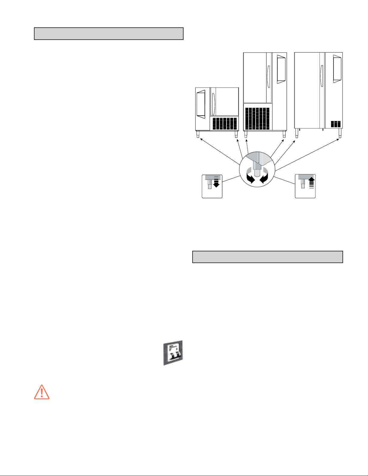
IMPORTANT:
Level the appliance, otherwise its operation could be compromised.
Adjust the height and level the appliance by means of the
leveling feet, checking that the door opens and closes properly.
+50 mm
+ 1.97 "
-10 mm
- 0.39 "
A.1.6 DATA PLATE POSITION
The data plate with all the appliance specifications is located on
the chilling unit compartment, on the lower left-hand side.
The plate bearing the appliance's PNC code and serial number
is located underneath the logo.
B.1 DESCRIPTION OF CYCLES
B.1.1 POSITIVE BLAST CHILLING
Positive blast chilling brings the food quickly to a temperature
of 37.4°F (+3°C).
Note that positive blast chilling is suitable for foods that are
going to be consumed within a few days.
There are two types of blast chilling:
• “SOFT” CHILLING
• “HARD” CHILLING
- “soft” chilling is recommended for foods such as vegetables
or pieces of food that are not very large or thick.
- “hard” chilling is recommended for larger sized pieces of
food.
B.1.2 NEGATIVE BLAST CHILLING OR FREEZING
Freezing allows foods to be preserved for longer periods (weeks
or months).
Quick freezing consists of reaching a negative temperature
(-0.4°F / -18°C) in the center of the product in the shortest
possible time. This ensures that when the product is thawed,
the tissues are not damaged and the food preserves its
aspect and nutritional ingredients.
With this cycle, the temperature of the food goes down to
between -4°F (-20°C) and -0.4°F (-18°C) when frozen.
9
B.1.3 MAINTENANCE CYCLE OR PRESERVATION CYCLE
The maintenance cycle is the maintenance of the food at a
chosen temperature so that it does not alter over time, is started
automatically at the end of the blast chilling or freezing cycle.
The preservation cycle is continuous. To interrupt it you have to
stop or make changes to the program.
B.1.4 STERILISATION CYCLE (appliances with germicidal light
option)
The UV lamps have a direct germicidal action and are used to
sterilise the surfaces and air in the appliance chamber. This
function can be used to sterilize kitchen utensils such as knives,
carving forks, etc. (the process should be done in two steps,
turning the utensils over to make sure both sides of utensils are
sterilized) and can be activated at the end of each working day.
Do not use this function if there is food in the chamber.
From left to right:
• Positive "SOFT CHILLING"
• Positive "HARD CHILLING"
• Positive "COOLER" maintenance (or preservation)
• Negative "BLAST FREEZING" chilling or freezing
• Negative "FREEZER" maintenance (or preservation)
When choosing a cycle, press the
the next option; the options are in a loop and so you can either
scroll forwards
or backwards .
button to move on to
ATTENTION:
The appliance has a safety device that switches off the lamps
when the doors are opened. This safety device is provided
because exposure to the U. V. rays emitted by the lamps is
harmful and can cause damage to eyes.
C.1 ANALYSIS OF USER INTERFACE
C.1.1 O•I I = ON / O = OFF
This button indicates the status of the appliance: I=On,O=Off.
When appliance is switch on, the whole interface lights up.
C.1.2 START/STOP CYCLE
This button starts or stops the selected cycle.
The selected cycle starts immediately when enabled. To stop
the cycle, keep the button pressed for at least 3 seconds.
If the door is closed when a cycle is started the button will light
up continuously. If the door is opened during a cycle it will start
blinking continuously.
1- "PREP" To optimize appliance performance when the need
arises, a preparation cycle can be chosen at the beginning of
a chilling cycle which is signalled on the temperature display
by the message “PREP”.
2- If the chiller has been inactive for a long time, the compressor
will be started by impulses to guarantee maximum efficiency.
C.1.3 SELECT CYCLES
C.1.4 PROGRAMS
Press the
mode. The appliance switches from standard cycle selection
mode to program mode and vice versa.
From left to right:
- Program P1
- Program P2
Associated with each standard cycle are 2 default programs that
can be varied by the user.
What is a program? For chilling, the user can change both the
chamber temperature and the chilling time and save the changes
in the memory for subsequent retrieval, and for maintenance the
user can set the chamber setpoint.
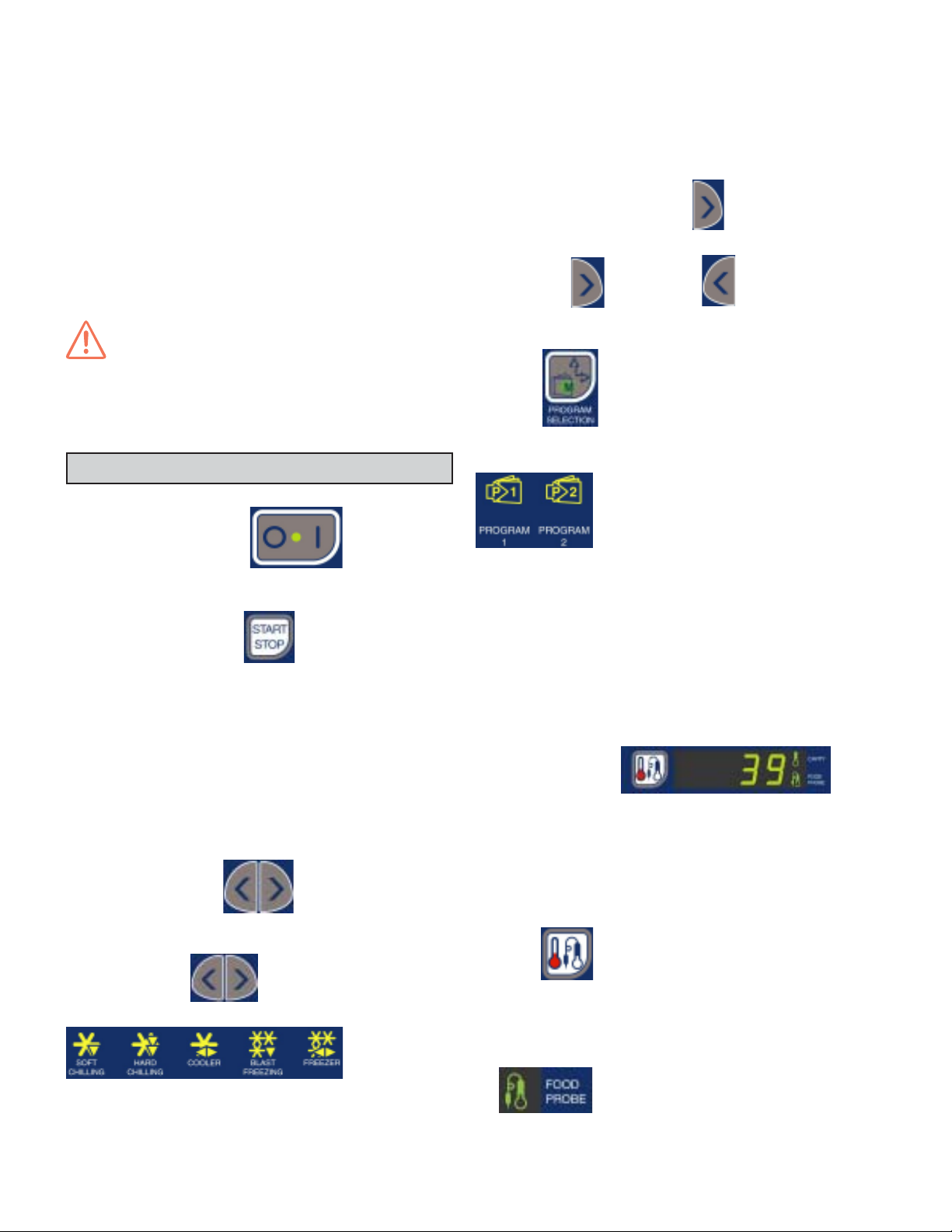
C.1.5 TEMPERATURE
The temperature display can display both the chamber temperature and the food (core) probe temperature.
If a cycle is running (i.e. positive or negative maintenance, timed
positive blast chilling or timed freezing), the temperature
displayed is the chamber temperature.
If a food (core) probe cycle is running, the food (core) probe
temperature will be displayed by default.
button to set the appliance for programs
The default setting on the appliance is the SOFT chilling cycle.
Use these buttons
options:
to select one of the following
10
Press the
chamber temperature and food (core) probe temperature.
The indicator light shows which of the two temperatures is being
displayed at that time:
- if the food (core) probe temperature is displayed, the FOOD
CORE PROBE TEMPERATURE INDICATOR LIGHT switches
on
- if the chamber temperature is displayed the CHAMBER TEM-
button in chilling cycles to switch between

PERATURE INDICATOR LIGHT switches on
Only one or the other can be enabled at one time. Both will not
active at the same time.
C.1.6 ALARM WARNING
The following indicator lights light up when an alarm occurs:
C.1.9 UTILITIES
When the button is pressed it lights up behind. Use the
When an HACCP alarm occurs, the indicator light
1- blinks continuously if the alarm is current. To
check the type of alarm, scroll to the utility section
(§ C.1.9) with the keys.
2- stays on continuously if the alarm has ended but
must still be addressed by the user.
When a service alarm occurs, the indicator light
1- blinks continuously if the alarm is current. To
check the type of alarm, scroll to the utility section
(§ C.1.9) with the keys.
2- stays on continuously if the alarm has ended but
must still be addressed by the user.
The type of alarm can be displayed by using the “Utilities menu”
functions (see sections C.1.9 for an explanation of the Utilities
menu, and section C.4 for instructions on how to display the
alarm types and descriptions of the alarms).
C.1.7 STANDARDS
The Standard indicator light is normally off. It lights up only when
the Reference Standard option is entered with the UTILITIES
button.
From left to right, the lights are: Electrolux Food Safe Mode 1,
Electrolux Food Safe Mode 2, U.S. Standard .
To display the appliance Standard setting, use the “Utilities
menu” functions (see sections C.1.9 and C.1.9.4).
buttons to scroll backwards and forwards and select
the utility. Press
After entering the “Utilities” menu, the system will go back to the
main menu if no button is pressed for 5 seconds.
See below for a DESCRIPTION OF THE UTILITIES FUNCTIONS.
C.1.9.1 MANUAL DEFROSTING
If the appliance is in the right conditions (indicator light
or or with the appliance on stand-by), this function
enables a manual defrosting cycle. The display shows the
message “dEfr” throughout the entire cycle.
If a manual defrosting is not possible (during a chilling cycle) the
message “ UTIL NONE” will appear on the display.
The selection is enabled only in preservation/maintenance and
when selecting the operating cycle.
When the defrosting is finished the system will go back to the
main configuration.
C.1.9.2 PROBE TEMPERATURES DISPLAY
to confirm.
minutes
C.1.8 TIME
The time display shows the total and remaining chilling time.
The display is enabled only during the running or selection of
a blast chilling cycle.
The display is switched off during the setting/running of a
maintenance cycle.
The TIMED CYCLE INDICATOR LIGHT
when a timed blast chilling cycle is running.
Set the blast chilling time in the selection stage.
lights up only
11
This function displays the probe temperatures, if there is more
than one probe inserted in the product.
If just one probe is used, see section C.1.5 for instructions on
how to display the temperature.
C.1.9.3 "UV"STERILIZATION CYCLE
(Function for appliances with germicidal light option)
The UV lamps have a direct germicidal action and are used to
sterilize the surfaces and air in the chamber of the appliance
(see section B.1.5)
To active "UV", no cycles must be running. When the cycle is
running the “TEMPERATURE” display shows the chamber
temperature. When the cycle is finished the system goes back
to the main menu.
If a sterilization cycle is not possible because of the status of the
appliance, the message “UTIL NONE” will appear on the display.
 Loading...