

Page 1
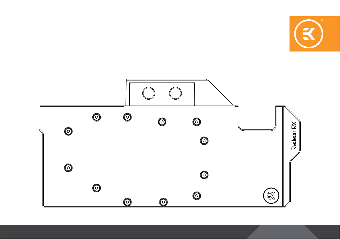
EK-Quantum
Vector RX 6800/6900
GPU WATER BLOCK
USER GUIDE
Page 2

Before you s tart using this prod uct, please follow t hese basic guidelines:
Carefully read the manual before beginning with the
installation process.
Remove your graphics card from the computer for the safest
mounting process to prevent any possible damage to your
GPU or its circuit board (PCB).
EK Fittings require only a small amount of force to screw
them firmly in place since the liquid seal is ensured with the
rubber O-ring gaskets.
The use of quality market-proven corrosion-inhibiting
coolants is always strongly recommended for any liquid
cooling system.
Do not use pure distilled water as a cooling liquid! For best
results, EK recommends the use of EK-CryoFuel Coolants.
Make sure to bleed air out of your water block thoroughly in
order to reach optimal performance.
Page 3

TABLE OF CONTENTS
BOX CONTENTS 4
WATER BLOCK DIMENSIONS 5
TECHNICAL SPECIFICATIONS AND WATER BLOCK PARTS 6
PREPARING THE GRAPHICS CARD 7
REMOVING THE S TOCK BACKPL ATE 7
REMOVING THE S TOCK COOLER 7
CHANGING THE STOCK 2SLOT I/O BRACKE T FOR THE SINGLESLOT I/O BRACKE T 8
CLEANING THE PCB 9
CUTTING AND PLACING THERMAL PADS 9
APPLYING THERMAL COMPOUND 10
INSTALLING THE WATER BLOCK 11
PLACING THE BLOCK ON THE GRAPHICS CARD 11
ATTACHING THE WATER BLOCK 11
CHECKING THE CONTACT IN CASE OF HIGH TEMPERATURES 12
INSERTING THE GRAPHICS CARD INTO THE CHASSIS 12
INSTALLATION OF FITTINGS AND TUBING 13
CONNECTING THE D-RGB LED STRIP 13
TESTING THE LOOP 14
SUPPORT AND SERVICE 15
SOCIAL MEDIA 15
- 3 -
Page 4
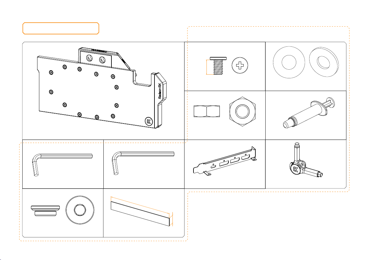
BOX CONTENTS
4 mm
Universal Mounting Mechanism – You may not need every
screw from this package.
EK-Quantum Vector RX 6800/6900
Allen Key 2 mm (1 pc)
EK-Plug G1/4 (2 pcs)
Allen Key 2.5 mm (1 pc)
120 mm
Thermal Pad F 1.0 mm (4 pcs)
M2.5x4 AX1 Screw (30 pcs)
M2.5 Nut (1 pc)
Single-Slot I/O Bracket (1 pc) EK-Loop Multi Allen Key (1 pc)
16 mm
- 4 -
PVC Washer M2.5 (28 pcs)
Thermal Grease (1 pc)
Page 5
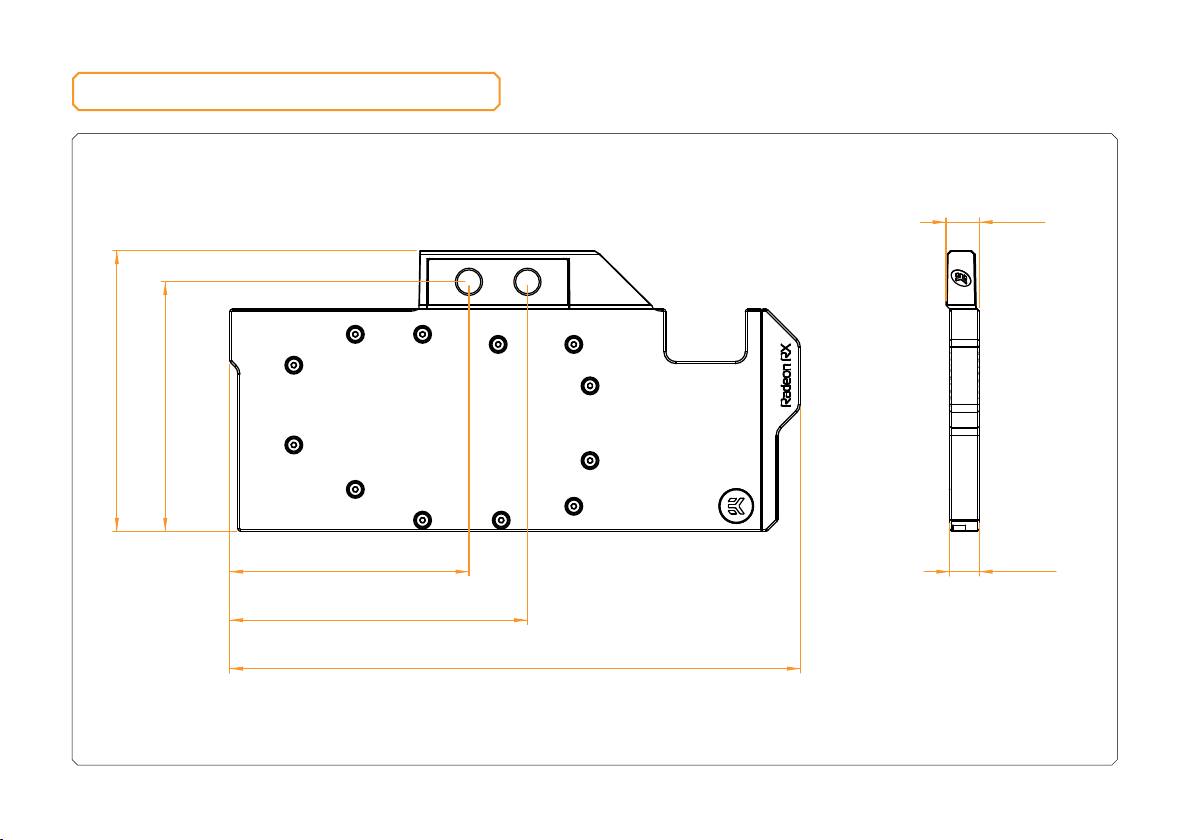
WATER BLOCK DIMENSIONS
138.95 mm
123.55 mm
282.90 mm
118.60 mm
147.60 mm
14.60 mm
16.50 mm
- 5 -
Page 6
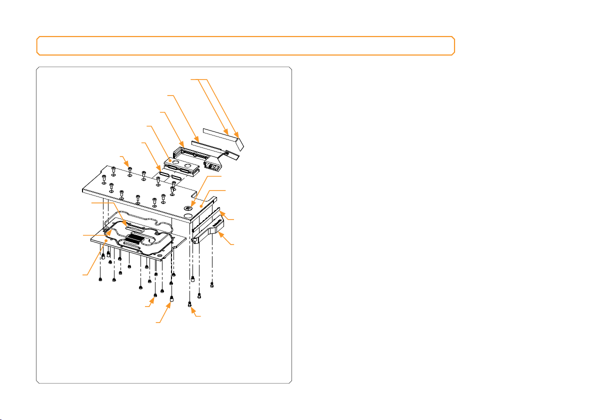
TECHNICAL SPECIFICATIONS AND WATER BLOCK PARTS
Technical Specification:
TERMINAL COVER STICKERS
TERMINAL COVER D-RGB LED
TERMINAL COVER
FC TERMINAL
TERMINAL O-RING 15 x 1 mm
M4 x 8 DIN798 4 SCREW
JE T PL AT E
MAIN O-RING
140 x 2 mm
COLDPLATE
STANDOFF M4/M2.5 x 2.50
STANDOFF M4/M2.5 x 6.60
EK BADGE
TO P PL ATE
(PLEXI, ACETAL)
D-RGB LED
STAND OUT
(PLEXI, ACETAL)
STANDOFF M4/M2.5 x 2.50
EXTENDED
- Dimensions (L xHxW): 283 x 139 x 16.5 mm
- D-RGB (Addressable RGB) Cable - Length: 500 mm
- D-RGB LED Count: Plexi – 8/Acetal – 8
- D-RGB Connector: Standard 3-Pin (+5V, Data, Blocked, Ground)
- 6 -
Page 7
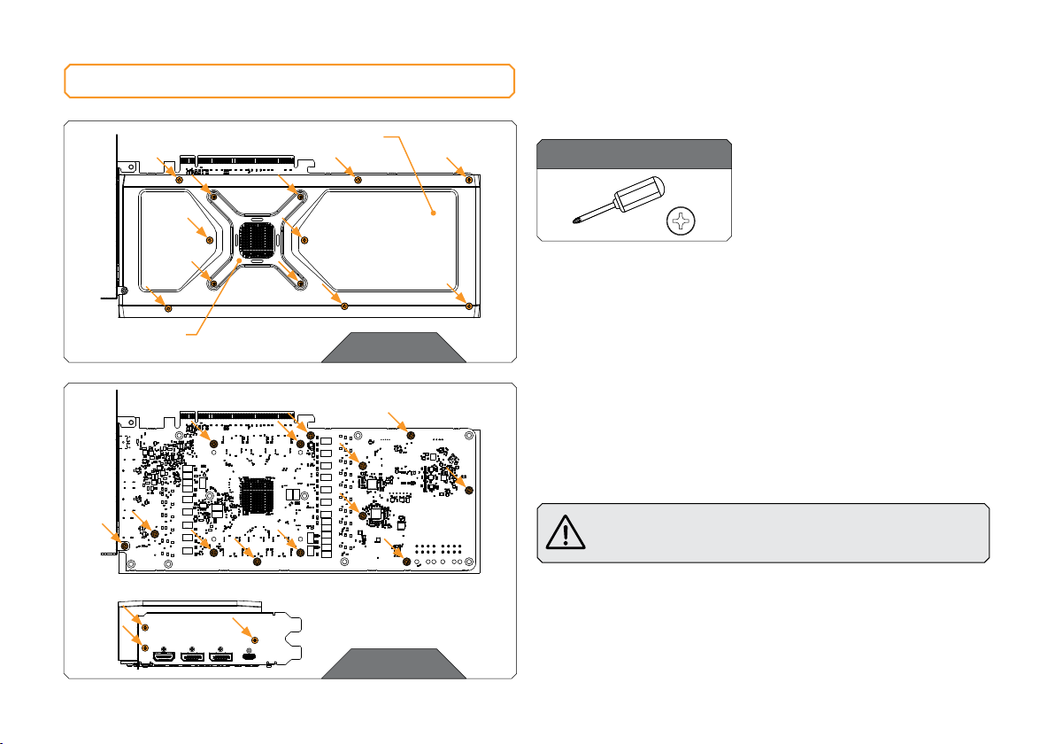
PREPARING THE GRAPHICS CARD
RETENTION
BRACKET
BA C KPL AT E
STEP 1
You will need the following tool:
Phillips Head Screwdriver
STEP 1
REMOVING THE STOCK BACKPLATE
Use the Phillips head screwdriver to unscrew the twelve (12) marked
screws. Evenly untighten four (4) retention bracket screws for easier
disassembly. Remove the Backplate and the Retention bracket from
the backside of the GPU.
STEP 2
REMOVING THE STOCK COOLER
Use the Phillips head screwdriver to unscrew the sixteen (16) marked
screws – thirteen (13) from the bottom side and three (3) from the side
of the I/O Bracket. Carefully detach the PCB from the stock cooler and
disconnect all cables connecting the stock cooler to the PCB.
Always remove the stock cooler slowly - it might be firmly
glued to the PCB with thermal pads.
STEP 2
- 7 -
Page 8
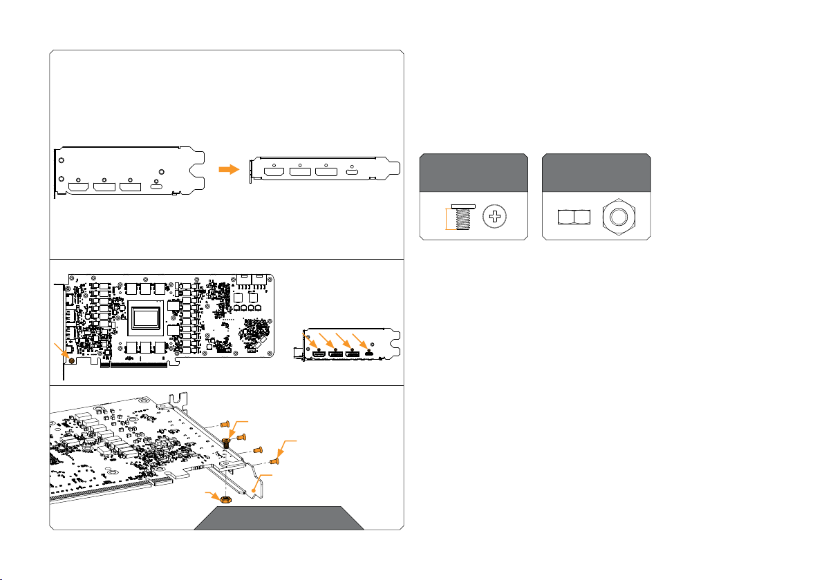
2-SLOT I/O BRACKET SINGLE SLOT BRACKET
OPTIONAL STEP
CHANGING THE STOCK 2SLOT I/O BRACKET FOR THE
SINGLESLOT I/O BRACKET
In case you prefer it that way, you can change the stock Two-Slot I/O
Bracket for the Single-Slot Bracket enclosed in this package.
For this Step, you will need:
M2.5 NUT
M2.5 x 4 AX1 SCREW
STOCK SCREWS
(4x)
SINGLE SLOT
BRACKET
OPTIONAL STEP
M2.5 x 4 AX1
Screw (1x)
4 mm
To remove the I/O Bracket, unscrew all five (5) screws marked in
a diagram. Save the four (4) marked screws for later since you will
need them to mount the new bracket.
Use four (4) stock screws that you saved and one M2.5 X 4 A X1
screw with the M2.5 nut to mount the Single-Slot Bracket.
- 8 -
M2.5 Nut
(1x)
Page 9
STEP 3
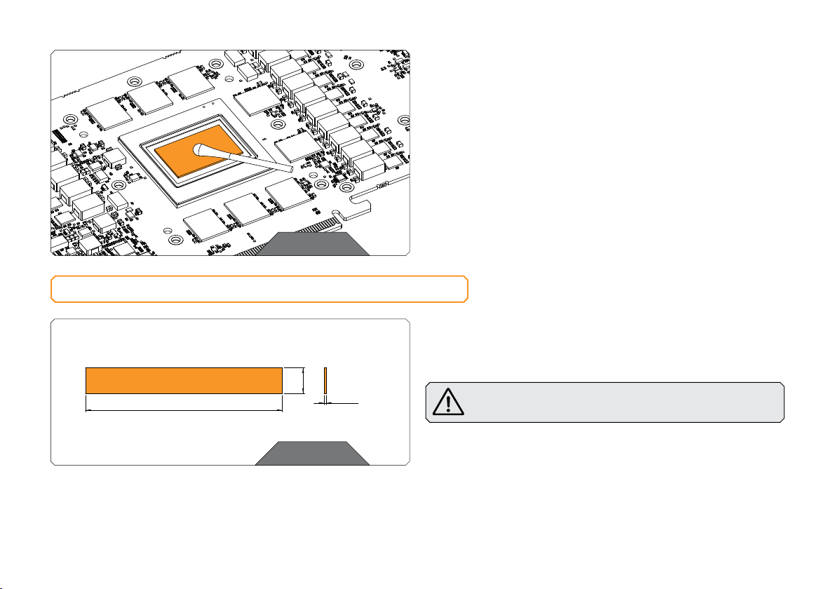
CLEANING THE PCB
Wipe off the remains of the original thermal compound using a
nonabrasive cloth or Q-tip, as shown in the sample image, until the
components and circuit board are completely clean. EK recommends
the use of denatured alcohol for removing TIM leftovers. After that,
remove all remaining stock thermal pads from the PCB.
STEP 3
CUTTING AND PLACING THERMAL PADS
STEP 1
Your GPU water block comes with thermal pads that have to be cut
Thermal Pad F – 1.0 mm (120 x 16 mm)
120mm
STEP 1
16 mm
1 mm
into smaller pieces to cover all the VRM components, such as COILs,
MOSFETs, and drivers.
Thermal pads:
4x Thermal Pad F 1.0 mm – (120 x 16 mm) EAN: 3830046996732
You must remove the protective foil from both sides of the
thermal pad before installation.
- 9 -
Page 10
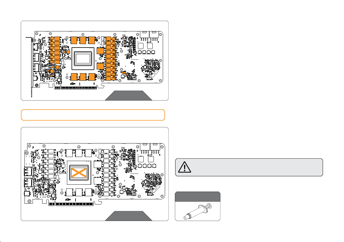
Thermal Pad F 1.0mm
STEP 2
APPLYING THERMAL COMPOUND
STEP 2
Once cut to size, thermal pads should be placed on the PCB, as
illustrated below. EK made sure to provide you with more than an
adequate quantity of thermal pads to complete this Step.
STEP 1
Apply the enclosed EK-TIM Ectotherm thermal grease (thermal
compound) on the CPU heat spreader – IHS – as shown in the
image. The layer of the thermal compound must be thin and even
over the entire surface of the IHS.
The excessive or uneven application of thermal grease
may lead to poor performance!
For this Step, you will need:
STEP 1
Thermal Grease
- 10 -
Page 11
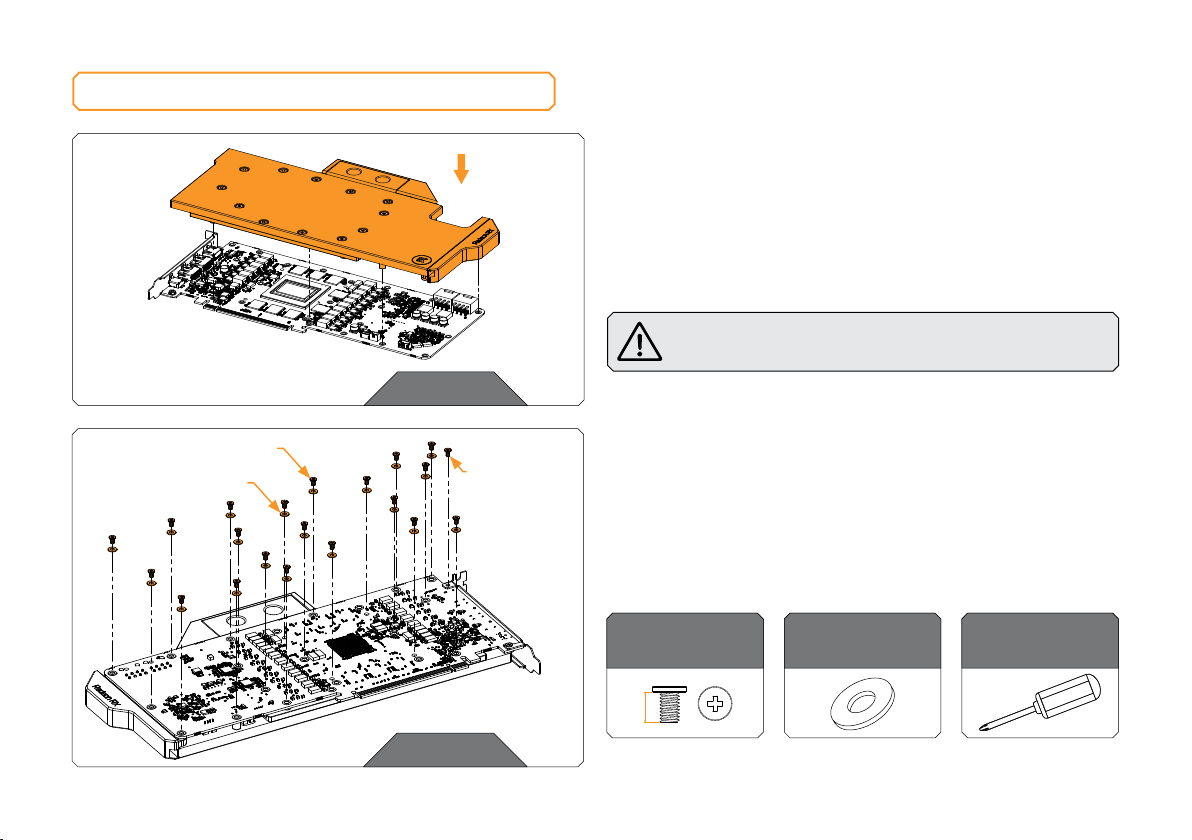
INSTALLING THE WATER BLOCK
STEP 1
STEP 1
PLACING THE BLOCK ON THE GRAPHICS CARD
This procedure is the same for all full-cover water blocks.
Carefully position the water block with preinstalled standoffs on
the graphics card. During this process, make sure you have aligned
mounting holes of the PCB with holes of the water block (same
applies to other tops).
Pay attention not to use too much force when pressing the
block down to the PCB since chip dies are prone to cracking.
M2.5 x 4 AX1
PVC WA SHER
STEP 2
WITHOUT
PVC WA SHER
STEP 2
ATTACHING THE WATER BLOCK
Use twenty-one (21) M2.5 X 4 AX1 screws and twenty (20) M2.5
PVC washers. Tighten the screws evenly using the Phillips head
screwdriver. EK recommends you star t tightening the screws around
the GPU core first and then continuing outward to prevent damage
to the GPU.
For this Step, you will need:
M2.5 x 4 AX1
21 pcs
4 mm
- 11 -
M 2.5 PVC Washer
20 pcs
Phillips Head
Screwdriver
Page 12
CHECKING THE CONTACT IN CASE OF HIGH TEMPERATURES
If neces sary, temporarily remove th e water block to check for uni form
surface contact between the block and components. Pay special
attention to the VRM section of the graphics card. Check whether
the water block makes contact with the intended integrated circuit.
Then repeat Steps from the previous section to re-attach the block.
In case you fail to obtain good contact, please check
again or contact our support ser vice at
https://www.ekwb.com/customer-support/.
INSERTING THE GRAPHICS CARD INTO THE CHASSIS
Carefully lift your graphics card with the installed water block and
insert it into your PC’s motherboard PCIexpress expansion slot.
Please keep in mind that your graphics card is heavier than before it
was equipped with the water block.
You need to be very careful when handling the
graphics card. Avoid all unnecessary manipulation
of the water block assembly that might damage your
card or water block.
- 12 -
Page 13
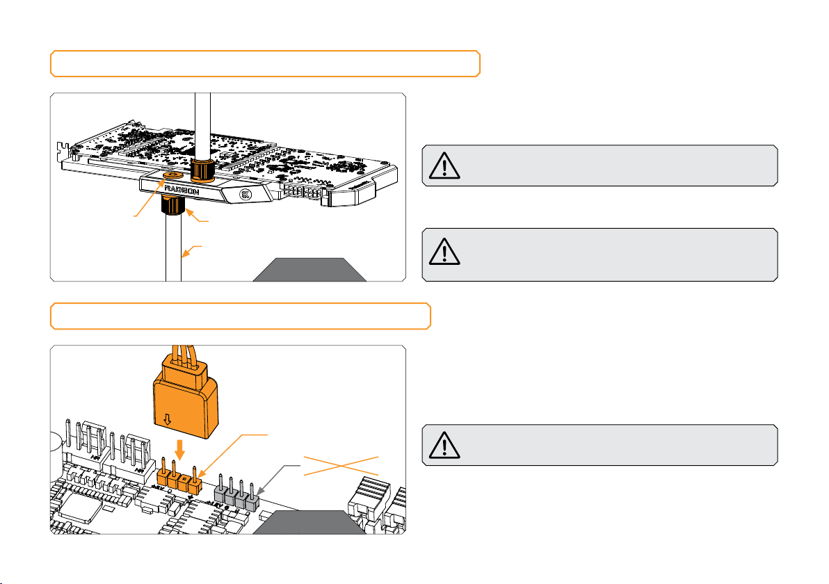
INSTALLATION OF FITTINGS AND TUBING
STEP 1
Screw in two (2) G1/4 threaded male fit tings. Attach the liquid
cooling tubes and connect the water block(s) to the cooling loop.
Do not forget to plug the remaining two openings with
enclosed EK-Plug G1/4 or its equivalent.
EK- PLUG
G1/4
EK-FITTING
TUBING
STEP 1
CONNECTING THE D-RGB LED STRIP
D-RGB HEADER
RGB HEADER
STEP 1
- 13 -
EK recommends using EK fittings with all EK water blocks.
CAUTION: When using connectors other than EK fittings,
pay special attention to the length of the fittings male G1/4”
thread - 5mm is the maximum G1/4” thread length allowed!
STEP 1
Plug the 4-pin D-RGB connector from the GPU water block to the
D-RGB Header on your motherboard or controller. The LED strip will
work only if the pin layout on the header is as follows: +5V, Data,
Empty, Ground.
Incorrect installation or installation to a wrong header can
damage the LED strip or the header itself!
Page 14

TESTING THE LOOP
To ensure the installation of EK components was successful, we
recommend you perform a 24-hour leak test.
When your loop is complete and filled with coolant, connect the
pump to a PSU outside your system. Do not connect power to
any of the other components. Turn on the PSU and let the pump
run continuously.
Inspect all parts of the loop, and in case the coolant leaks, fix
the issue and repeat the testing process. To prevent possible
damage, please ensure all hardware is dr y before the system is
powered on.
- 14 -
Page 15
SUPPORT AND SERVICE
In case you need assistance, please contact:
http://support.ekwb.com/
EKWB d.o.o.
Pod lipami 18
1218 Komenda
Slovenia - EU
SOCIAL MEDIA
EKWaterBlocks
@EKWaterBlocks
ekwaterblocks
EKWBofficial
ekwaterblocks
 Loading...