

EKWB EK-Quantum Vector RTX RE, EK-Quantum Vector RE Ti, EK-Quantum Vector Titan RTX Installation manual
Page 1
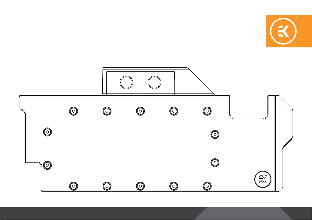
EKQuantum
Vector RTX RE / RE Ti / Titan RTX
GPU WATER BLOC K
INSTALLATION MANUAL
Page 2

This product is compatible with RTX 2070, RTX 2080, RTX 2080 Ti
and Titan RTX graphic cards. It is intended for installation only by
exper t users. Please c onsult with a quali fied technician for i nstallation.
Improper installation may result in damage to your equipment. EK
Water Blocks assumes no liability whatsoever, expressed or implied,
for the use of these products, nor their installation. The following
instructions are subject to change without notice. Please visit our
web site at www.ekwb.com for updates. Before installation of this
product please read important notice, disclosure and warrant y
conditions printed on the back of the box.
Before you start using this product please follow these basic
guidelines:
Please carefully read the manual before beginning with the
installation process!
Please remove your graphics card from the computer to assure
safest mounting process in order to prevent any possible
damages to your GPU and/or graphics card circuit board (PCB).
The EK Fittings require only a small amount of force to screw
them firmly in place since the liquid seal is ensured by the
rubber O-ring gaskets.
The use of corrosion inhibiting coolants is a lways recommende d
for liquid cooling systems, and mandatory for nickel plated
water blocks!
Do not use pure dist illed water! For best results EK recommends
the use of EK-CryoFuel coolants!
Make sure to thoroughly bleed air out of your water block, or
you will not reach optimal performance!
- 2 -
Page 3

TABLE OF CONTENT
PREPARING YOUR GRAPHIC CARD 4
INSTALLING THE WATER BLOCK FOR RTX 2070 / RTX 2080 / RTX 2080 Ti / Titan RTX GRAPHIC CARD 7
CHECKING FOR CONTACTS 8
INSTALLATION OF FITTINGS AND TUBING 8
INSERTING THE CARD IN YOUR PC CASE 9
REQUIRED TOOLS 9
CONNECTING THE D-RGB LED STRIP 10
SUPPORT AND SERVICE 11
SOCIAL MEDIA 11
- 3 -
Page 4
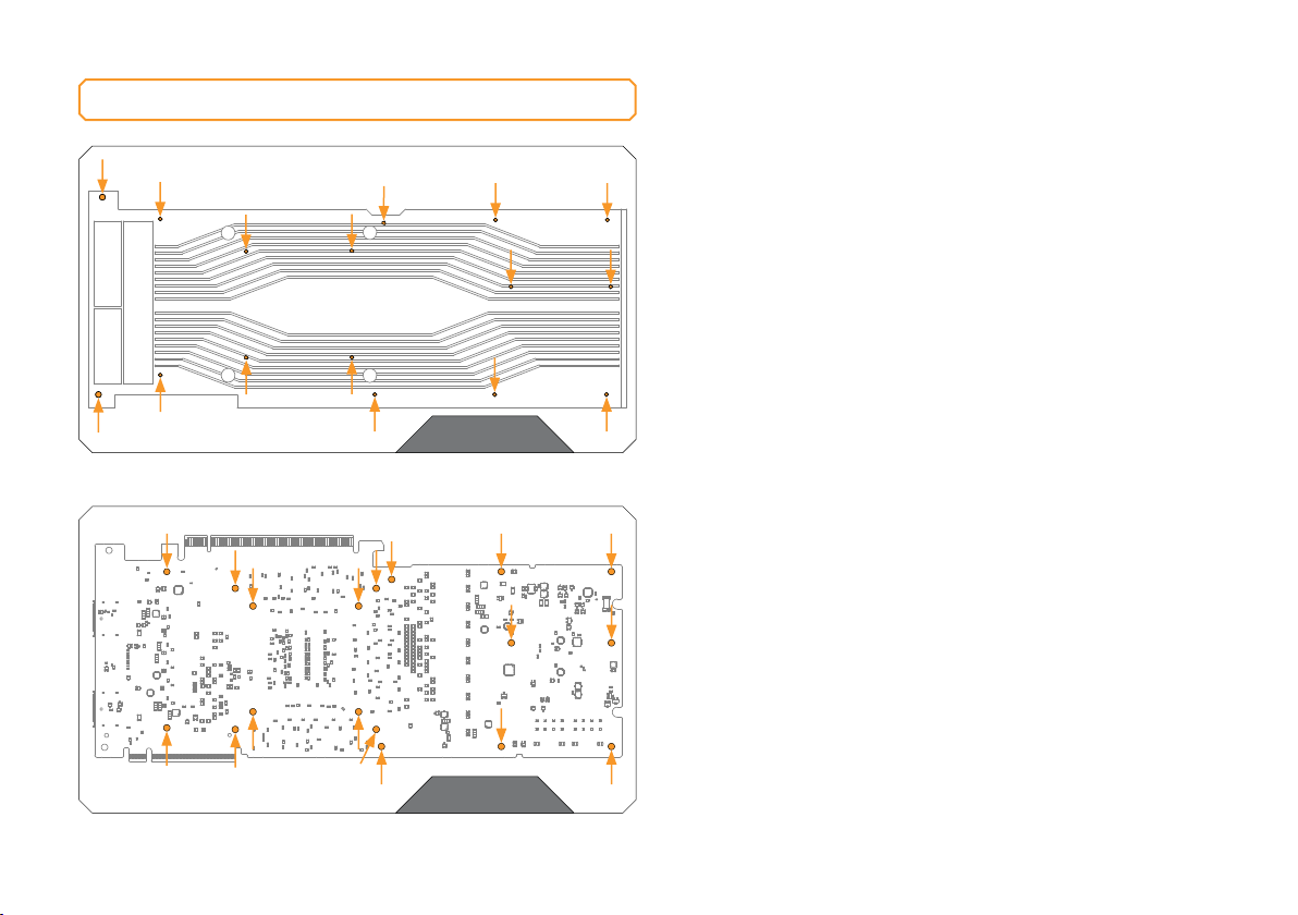
PREPARING YOUR GRAPHIC CARD
STEP 1
STEP 1
REMOVING FACTORY PROVIDED BACKPLATE
Remove all encircled screws using Phillips screwdriver. All heat
sink assembly screws should be removed, including self-adhesive
washers on both sides of the PCB (if present).
STEP 2
REMOVING STOCK COOLER
Remove all encircled screws using Phillips screwdriver (4 spring
screws around the GPU chip) and 4 mm hex socket. All heat sink
assembly screws should be removed, including self-adhesive
washers on both sides of the PCB (if present). After you remove the
housing do not forget to unplug the fans.
STEP 2
- 4 -
Page 5
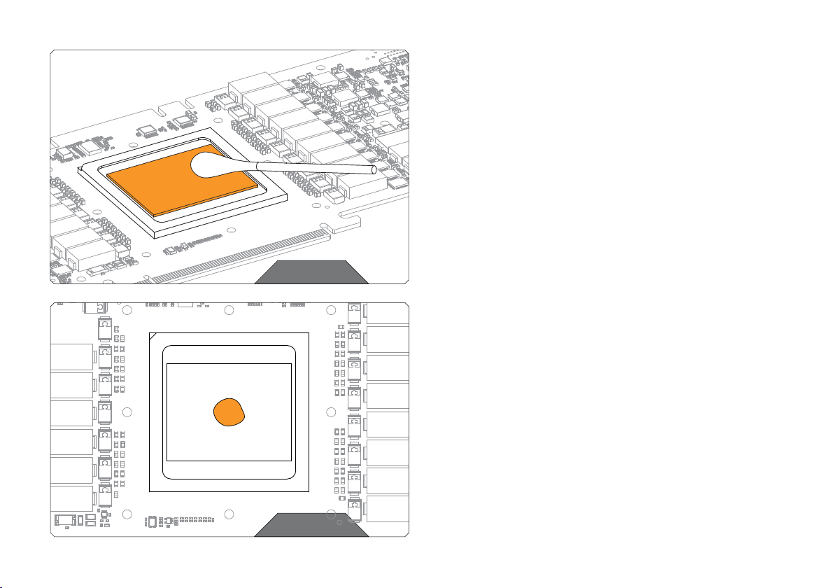
STEP 3
STEP 3
CLEANING THE PCB
Carefully d etach the original s tock cooler af ter removing all s crews securing
it to the board. Wipe off the remains (by using non–abrasive cloth or q-tip,
as shown on sample image) of the original thermal compound until the
components and circuit board are completely clean. EKWB recommends
the use of denatured alcohol for removing TIM leftovers.
STEP 4
APPLYING THERMAL COMPOUND
Wipe off the remains (by using non–abrasive cloth or q-tip) of the original
thermal compound until the components and circuit board are completely
clean. Apply thermal compound: lightly coat NVIDIA GPU chip with
enclosed EK-TIM Ectotherm thermal grease. EK recommends blob or line
method of applying the enclosed thermal compound for best performance
(see sample picture).
STEP 4
- 5 -
Page 6
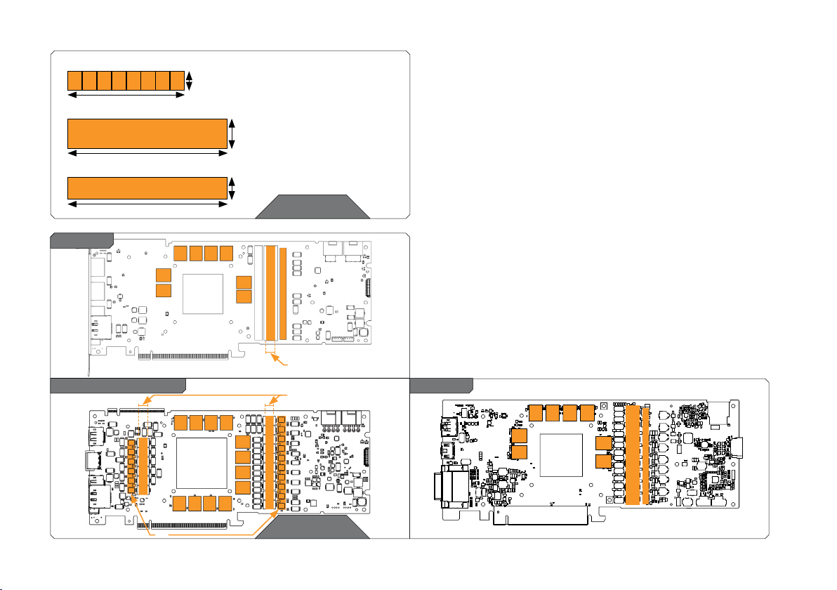
1: Thermal pad E – 0.5 mm (for memory IC):
16
2: Thermal pad G – 1.0 mm (for MOSFET ):
3: Thermal pad F – 1.0 mm (for COILs):
100
120
120
24
16
STEP 5
STEP 5
CUTTING THERMAL PADS
Your block comes with thermal pads, some of which are already pre-cut.
Others have to be cut to smaller chunks in order to cover all the VRM
components such as COILs, MOSFETs and drivers. PLEASE REMOVE
THE PROTECTIVE FOIL FROM BOTH SIDES OF THE THERMAL PADS
PRIOR TO INSTALLATION.
Replacement thermal pads:
Thermal Pad E – 0.5 mm (RAM 8x) – (EAN: 3830046996688)
Thermal Pad G – 1.0 mm (120 x 24 mm) – (EAN: 3830046996770)
Thermal PAD F 1,0 mm - (120 x 16 mm) – (EAN:3830046996732)
RTX 2080
1
1
RTX 2080 Ti / Titan RTX
3
2
1 1 1
1
1 11 1
1 11 1
STEP 6
PLACING THERMAL PADS ON PCB
Place thermal pads on the circuit board as shown on the picture below.
1
3
2
1
MAX 8 mm wide
thermal pad
MAX 8 mm wide
thermal pad
1
1
3
1
1
Refer to numbering in previous picture when applying thermal pads of
different sizes or thicknesses. EK made sure to provide customers with
more than adequate quantity of thermal pads to complete this step.
RTX 2070
1
1 1 1
1
1
1
2
3
1
STEP 6
- 6 -
Page 7
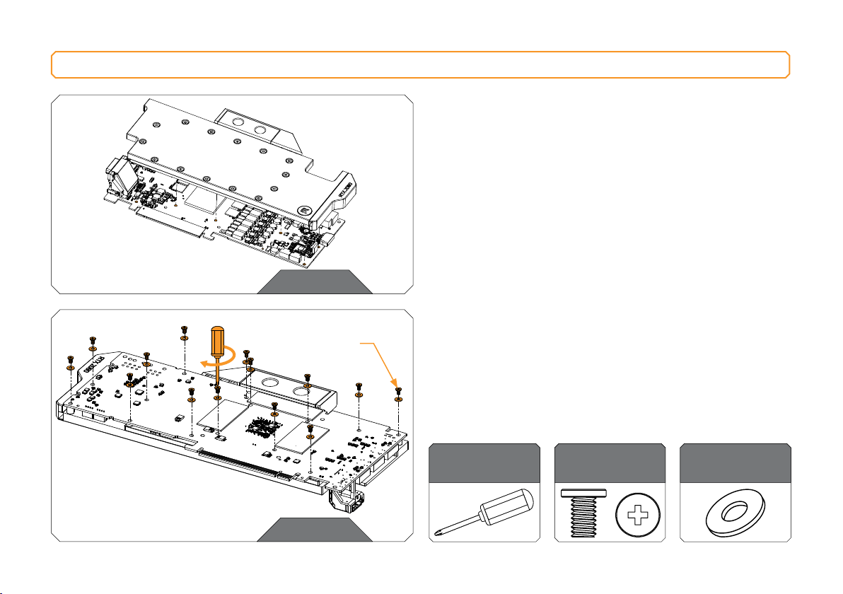
INSTALLING THE WATER BLOCK FOR RTX 2070 / RTX 2080 / RTX 2080 Ti / Titan RTX GRAPHIC CARD
STEP 1
PLACING THE BLOCK ON TO THE GRAPHICS CARD
Carefully position the water block with preinstalled standoffs on to
the graphics card. During this process please make sure you align
mounting holes on the PCB with holes on the water block (same
applies for other tops). Also pay attention not to use too much
force by pressing the block down to the PCB. Chip dies are prone to
cracking. Procedure is the same for all Full Cover water blocks.
STEP 1
STEP 1
M2,5 x 4 AX1
ATTACHING THE BLOCK TO THE GRAPHIC CARD
Use a Philips screwdriver screw with the enclosed M2,5 x 4 AX1
screws. EKWB recommends users to start tightening the screws
around the GPU core and continue outwards. Always use a plastic
washer under each and every screw! If the washer is already present
on the circuit board (usually around the four GPU core screw holes)
there is no need for additional washer.
In this step you will need:
STEP 2
- 7 -
Phillips-head
screwdriver
M 2.5 x 4 AX1
14 pcs
M 2.5 PVC washer
14 pcs
Page 8
CHECKING FOR CONTACTS
If necessary temporarily remove the water block to check for uniform
surface contact between the block and the components, pay special
attention to the VRM section of the graphics card. Check whether
the water block makes contact with the intended integrated circuit.
Then repeat sub-steps in previous section to re-attach the block.
In case you fail to obtain good contact, please check again that
your thermal pad thickness or contact our support service at
http://www.ekwb.com/support.
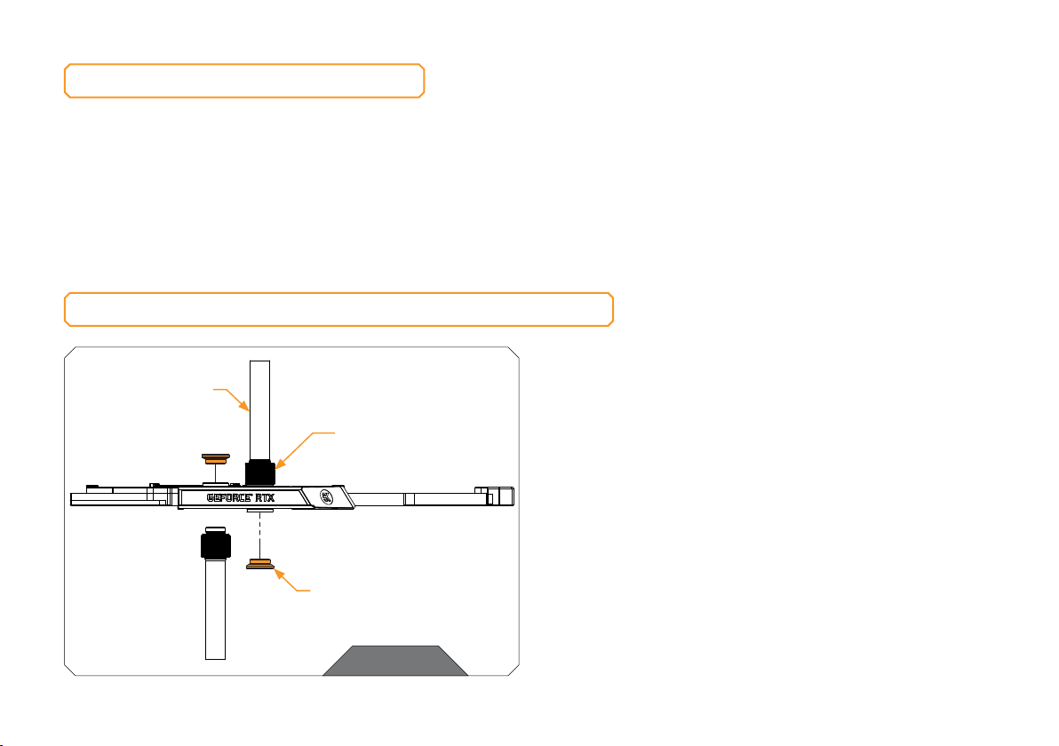
INSTALLATION OF FITTINGS AND TUBING
Screw in the two G1/4 threaded male fit tings. Attach the liquid
cooling tubes and connect the water-block(s) into the cooling circuit.
Tubing
EK-ACF Fitting
EK-P lug G1/4
EKWB recommends using EK Fittings with the EK-Vector series
water blocks. To ensure that the tubes are securely attached to the
barb/fittings, please use hose clamps or an appropriate substitute.
You can use any opening as an inlet/outlet port. Do not forget to
plug the remaining two opening with enclosed EK-Plug G1/4 or
equivalent.
CAUTION: In case of using connectors other than EK Fittings, take
special attention to the length of the fittings’ male G1/4” thread. 5
mm is the maximum allowed G1/4” thread length!
STEP 1
- 8 -
Page 9
INSERTING THE CARD IN YOUR PC CASE
Carefully lift your graphics card with installed block and insert it in
your PC’s motherboard PCI-express expansion slot. Please bear in
mind that your graphics card is probably heavier than when it was
equipped with original heat sink fan assembly. One needs to be
very careful when handling the graphics card. Avoid all un-needed
manipulation of the VGA/water block assembly that might damage
your card or water block during final installation.
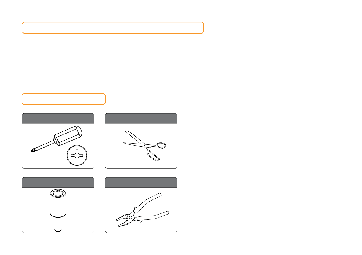
REQUIRED TOOLS
Phillips-head screwdriver Scissors
4mm hex socket Optional: pliers
- 9 -
Page 10
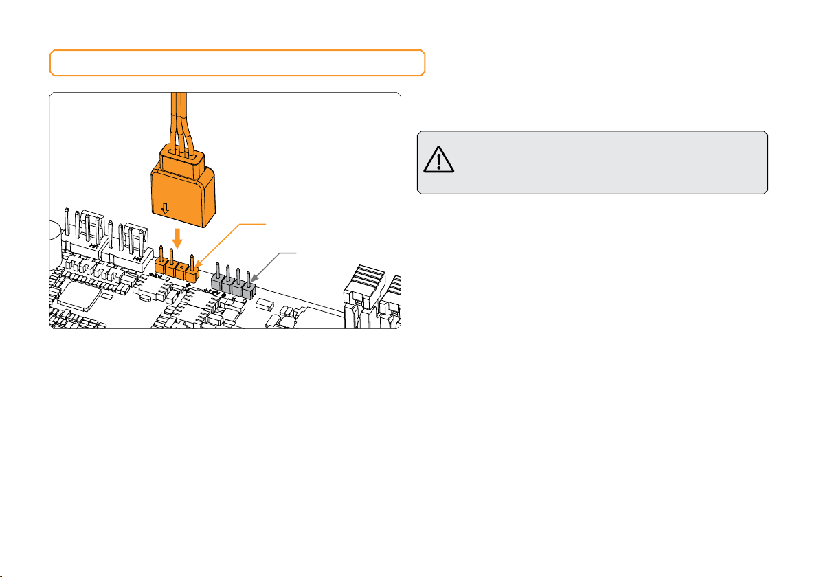
CONNECTING THE D-RGB LED STRIP
D-RGB Header
RGB Header
Plug the 3-pin connector from Monoblock D-RGB LED strip to the
motherboard.
Please ensure that the arrow indicated on the connector is
plugged into t he +5V line as indicated on yo ur motherboard.
Failure to do so will damage your motherboard or LED s trip.
- 10 -
Page 11

SUPPORT AND SERVICE
For assistance please contact:
http://support.ekwb.com/
EKWB d.o.o.
Pod lipami 18
1218 Komenda
Slovenia - EU
SOCIAL MEDIA
EKWaterBlocks
@EKWaterBlocks
ekwaterblocks
EKWBofficial
ekwaterblocks
 Loading...