

Page 1

Color LCD Monitor
Installation Manual
Important
Please read this Installation Manual, the Instruction Manual and the
Setup Manual carefully to familiarize yourself with safe and effective
usage.
• The latest manual is available for download from our web site:
http://www.eizoglobal.com
Page 2

2
About this manual
Setup Manual
Describes precautions and setup processes from network camera
connection to camera image display.
Instruction Manual
Describes operation of network cameras and live image screen
menus, etc.
Installation Manual
(this manual)
Describes network camera registration and function setup, monitor
system setup, etc.
This product has been adjusted specically for use in the region to which it was originally shipped. If
operated outside this region, the product may not perform as stated in the specications.
No part of this manual may be reproduced, stored in a retrieval system, or transmitted, in any form or by
any means, electronic, mechanical, or otherwise, without the prior written permission of EIZO Corporation.
EIZO Corporation is under no obligation to hold any submitted material or information condential unless
prior arrangements are made pursuant to EIZO Corporation’s receipt of said information. Although every
effort has been made to ensure that this manual provides up-to-date information, please note that EIZO
monitor specications are subject to change without notice.
Page 3

3
Notice for this monitor
Notice for this monitor
This product is suited for displaying surveillance camera images.
This product has been adjusted specically for use in the region to which it was originally shipped. If the
product is used outside the region, it may not operate as specied in the specications.
This product may not be covered by warranty for uses other than those described in this manual.
The specications noted in this manual are only applicable when the following are used:
• Power cords provided with the product
• Signal cables specied by us
Only use optional products manufactured or specied by us with this product.
When installing the monitor in a rack, ensure that there is adequate space around the sides, back and top of
the monitor.
If you place this product on a lacquer-coated desk, the color may adhere to the bottom of the stand due to
the composition of the rubber. Check the desk surface before use.
It takes about 30 minutes for the performance of electrical parts to stabilize. Please wait 30 minutes or more
after the monitor power has been turned on, and then adjust the monitor.
Monitors should be set to a lower brightness to reduce changes in luminosity caused by long-term use and
maintain a stable display.
When the screen image is changed after displaying the same image for extended periods of time, an
afterimage may appear. Use the screen saver or power save function to avoid displaying the same image for
extended periods of time.
Periodic cleaning is recommended to keep the monitor looking new and to prolong its operation lifetime (For
details, refer to the Instruction Manual.).
The LCD panel is manufactured using high-precision technology. Although, missing pixels or lit pixels may
appear on the LCD panel, this is not a malfunction. Percentage of effective dots: 99.9994 % or higher.
The backlight of the LCD panel has a xed lifetime. When the screen becomes dark or begins to icker,
please contact your local EIZO representative.
Do not press on the panel or edge of the frame strongly, as this may result in display malfunctions, such
as interference patterns, etc. If pressure is continually applied to the panel, it may deteriorate or damage
your panel. (If the pressure marks remain on the panel, leave the monitor with a black or white screen. The
symptom may disappear.)
Do not scratch or press on the panel with any sharp objects, as this may result in damage to the panel. Do
not attempt to brush with tissues as this may scratch the panel.
When the monitor is cold and brought into a room or the room temperature goes up quickly, dew
condensation may occur on the interior and exterior surfaces of the monitor. In that case, do not turn the
monitor on. Instead wait until the dew condensation disappears, otherwise it may cause some damage to the
monitor.
Page 4

4
Notice for this monitor
Disclaimer
EIZO shall not be liable in any way to any person whatsoever for the occurrences described below.
1. Any incidental, special or consequential disruption or damage directly or indirectly arising in
connection with this product.
2. Any loss, damage or cost resulting from misuse or neglect.
3. Any malfunction or failure occurring after unauthorized disassembly, repair or alteration regardless
of its cause.
4. Any inconvenience, loss or damage caused by the inability to display images due to any reason or
cause including malfunctions or failures in this product.
5. Any failure or consequential inconvenience, loss or damage due to malfunction or failure of a
combined system that comprises this product and any third party products.
6. Any consequential claim for compensation or complaint based on privacy violation or any other
reason by individuals or entities recorded in the surveillance images which are made public for/by
whatever cause or used.
7. Any loss of registered data for whatever cause.
While this product displays camera surveillance images, the use of this product alone does not directly
prevent crime.
Cautions for Network Use
Because this product is used by connecting to networks, the following risks apply
1. Leakage of information through this product.
2. Unauthorized operation of this product by a malicious third party.
3. Interference or suspension of the use of this product by a malicious third party.
In order to prevent the above described damage, it is the user’s responsibility to implement adequate
network security measures including the measures described below.
• Use this product with a safety-ensured network by using a rewall or other network security
systems.
• Change the administrator password periodically.
Page 5

5
CONTENTS
CONTENTS
Notice for this monitor ......................................... 3
Disclaimer ................................................................. 4
Cautions for Network Use ....................................... 4
CONTENTS ............................................................. 5
Chapter 1 Product overview .............................. 6
1-1. Features ......................................................... 6
1-2. SystemConguration .................................. 7
1-3. Supported Network Cameras ...................... 7
Chapter 2
Conguringfromthemonitorscreen
... 8
2-1. BeforeConguration .................................... 8
2-2. Setting Screen ............................................... 9
●
Basic operations .............................................. 9
2-3. Setting Network Cameras ...........................11
●
To automatically discover network cameras
...11
●
To manually register network cameras ..........12
●
To set network camera functions ...................14
2-4. Setting Display Positions of
Camera Images ........................................... 20
2-5. Setting Smart Functions .............................21
2-6. ConguringSystemSettings .................... 22
2-7. Setting User Information ............................ 32
●
To register new user information ................... 32
●
To change user information .......................... 33
●
To delete user information ............................. 33
2-8. Displaying Operation Logs ........................ 34
●
To display log data ........................................ 34
●
To save log data ............................................ 35
Chapter 3
ConguringfromaWebBrowser
... 36
3-1. BeforeConguration .................................. 36
3-2. Setting Screen ..............................................37
●
Basic Operations ............................................37
3-3. Basic Information ....................................... 38
●
System Status ............................................... 38
●
Camera and Display Position/Date
and TimeSettings/Network Settings/
Communication Settings ............................... 39
3-4. Setting Network Cameras .......................... 40
●
To automatically detect cameras .................. 40
●
Reading CSV Files .........................................42
●
Adding a Camera .......................................... 43
●
Changing Camera Information ...................... 45
●
Deleting Camera Information .........................47
●
Save Camera Information ............................. 48
3-5. Setting Display Positions of
Camera Images ........................................... 48
●
Setting Display Positions .............................. 49
●
Other Display Settings .................................. 50
●
Setting Smart Functions .................................51
3-6. ConguringSystemSettings .................... 52
●
Date and Time ................................................52
●
Network Settings ........................................... 55
●
Communication Settings ............................... 56
●
Other System Settings .................................. 57
●
Maintenance .................................................. 58
3-7. Setting User Information .............................61
●
Adding User Information ................................61
●
Changing User Information ........................... 62
●
To delete user information ............................. 63
3-8. Displaying Operation Logs ........................ 64
●
Displaying logs .............................................. 64
●
Displaying the system log ............................. 64
3-9. Setting the Live Image Screen .................. 65
Chapter 4 Troubleshooting .............................. 66
4-1. Imaging problems ....................................... 66
4-2. Setting Problems ........................................ 67
Chapter 5 Reference ........................................ 68
5-1. List of setting items .................................... 68
Chapter 6 Glossary .......................................... 73
Page 6

6
Chapter 1 Product overview
Chapter 1 Product overview
This color LCD monitor can display images from up to 16 network cameras*1.
This manual describes network camera setup, monitor system setup and specications, etc.
For information on setup, see “Chapter 2 Conguring from the monitor screen” (page 8) and “Chapter 3
Conguring from a Web Browser” (page 36).
*1 A type of camera which converts images into network signals and transmits the signals.
1-1. Features
• 23.0″ wide format LCD
• Supports a resolution of 1920 × 1080
• LCD panel with wide eld of view adopted
IPS LCD panel with 178° horizontal and vertical viewing angles
• LED backlight LCD panel
No mercury, a hazardous substance, is used.
• Receives input video signals from network cameras.
- Compatible with video compression formats H.264 and MJPEG.
- Up to 16 network cameras can be registered and displayed.
- Images from multiple network cameras can be displayed simultaneously (1-/4-/8-/9-/16-screen
display).
- Network cameras can be controlled from the monitor.
- Unicast and Multicast video signals can be displayed.
• Equipped with Easy Setup function
Necessary settings for setup can be performed with a wizard.
• Compatible with ONVIF Prole S
• Provides display modes (DAY/NIGHT) suitable for surveillance camera images
• EIZO’s unique “Smart” technology
- Smart Resolution function
This function adjusts the perceived resolution of the images so that the blurs are reduced and images are
displayed vividly and clearly.
- Smart Insight function
This function analyzes the image and corrects the brightness for each pixel to make dark area of images
visible.
- Noise Reduction function
This function reduces the amount of block noise that occurs due to video compression.
• Can be operated remotely with the remote control.
• You can register a network camera and congure the live image screen using your web browser
• You can have an alert displayed on the live image screen when communication with a network
camera is lost.
• You can save the settings to a USB storage device and load the settings.
• A 2-year long-term warranty for 24-hour continuous use
Page 7

7
Chapter 1 Product overview
1-2. SystemConguration
You can communicate with network cameras, display video on the monitor, operate cameras, and so on.
FDF2304W-IP
HDMI
Ethernet
Network camera
*1
Network hub
HDMI device
*2
(Network video recorder etc.)
*1 Up to 16 network cameras can be registered.
*2 Use an HDMI device (e.g. network video recorder) if necessary.
1-3. Supported Network Cameras
This product supports the following network cameras:
• Panasonic i-pro series network cameras
• ONVIF Prole S-compatible network cameras
Attention
• Supported network cameras vary depending on the monitor’s software version. Check the software version of
the monitor you are using, then check our website (http://www.eizoglobal.com) for details on supported network
cameras. For information on how to check the software version, see “2-6. Conguring System Settings” (page
22).
• For installation and settings of network cameras, also check the network camera’s manual.
Page 8

8
Chapter 2 Conguring from the monitor screen
Chapter 2 Conguringfromthemonitor
screen
You can congure and operate network cameras from the monitor screen. To congure from your web
browser, see “Chapter 3 Conguring from a Web Browser” (page 36).
2-1. BeforeConguration
To congure from the monitor screen, you need to be logged in to the system.
Conguration of this product is allowed only by ADMIN level users.
Be sure to log in to the system with a user account of this level.
Procedure
1. Press
on the front of the monitor or on the remote control.
The power indicator lights up blue and the live image screen is displayed.
(For information on the live image screen, refer to the Installation Manual.
2. Select (Login) under “System”.
The login screen is displayed.
5
2
3
4
3. Enter a username and a password.
4. Select “Login”.
The display changes back to the live image screen.
5. Select (Setting).
The setting screen is displayed.
(For information on the setting screen, see “2-2. Setting Screen” (page 9).
Note
• See “To enter characters” (page 10) for the character entry method.
• The following user information is set by default:
- Username: “admin”
- Password: “admin”
- User Level: “ADMIN”
• For information on user settings, see “2-7. Setting User Information” (page 32).
• It is recommended that you log out after completing the setup, so as to prevent a third party from operating
the network camera or altering the settings.
Attention
• When the monitor power is turned off while the user is logged in, the user is logged out from the system
automatically. In such a case, you cannot display the web interface in your web browser.
Page 9

9
Chapter 2 Conguring from the monitor screen
2-2. Setting Screen
The setting screen is used for various settings such as network camera registration and monitor system
settings.
●
Basic operations
List of setting items The setting screen of the selected item is displayed.
To select an item
Press the
/ / / buttons.
Toconrmaselecteditem
Press
.
To change a setting
• With setting buttons Press
.
• With list box 1. Press
.
An option list is displayed.
2. Select the setting with or .
3. Press .
To return to the previous menu level
Press
.
Note
• When canceling a setting change in process, press .
Page 10

10
Chapter 2 Conguring from the monitor screen
To enter characters
1. Press
.
The text eld is highlighted in green.
2. Press the number buttons ( to ).
Press a button consecutively to change over to the character next in order. For the order of character entr y,
refer to the table shown below.
Button Input characters
0 - _ : . / (sp ac e)
1
a b c A B C 2
d e f D E F 3
g h i G H I 4
j k l J K L 5
m n o M N O 6
p q r s P Q R S 7
t u v T U V 8
w x y z W X Y Z 9
To enter a new character, press
.
To delete a character, press
.
3. Press .
Note
• Entering network addresses
Network address text boxes are separated by [.] (a period mark).
- When a three-digit number is entered, the cursor automatically moves to the next entry position.
- When entering a two-digit or one-digit number, press
to move to the next entry position.
- When using a mouse, enter [.] (a period mark) to move to the next entry position.
To exit the setting screen
1. Select “Exit” from the list of setting items with
.
2. Press
.
Attention
• While settings are being applied (registered) to the system, a “Setting” (“Registering”) message is displayed. Do
not turn off the monitor while the message is displayed. Otherwise, setting information may be lost.
Page 11
11
Chapter 2 Conguring from the monitor screen
2-3. Setting Network Cameras
●
To automatically discover network cameras
Discover network cameras on the network automatically and register them to the system.
This procedure is for setting network cameras connected after performing “Easy Setup” upon initial
startup of the monitor.
Attention
• Only the network cameras installed in the same subnet as the monitor are detected. If a network camera is
installed in a different subnet, the camera must be registered manually (see “To manually register network
cameras” (page 12)).
• When network cameras are not detected by automatic discovery, see “Chapter 4 Troubleshooting” (page
66).
• For information on “Easy Setup”, refer to the Setup Manual.
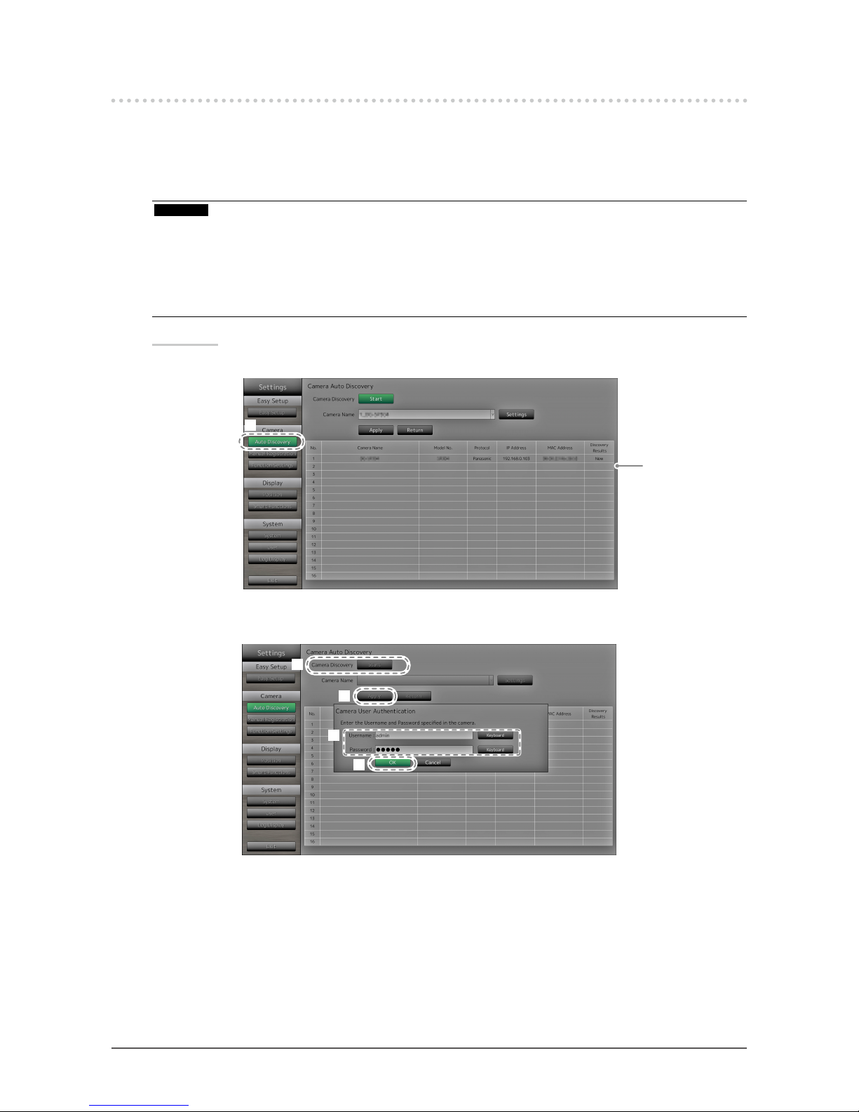
Procedure
1. Select “Auto Discovery”.
Displays registered
cameras.
1
2. Select “Start” at “Camera Discovery”.
The user authentication screen is displayed.
2
3
5
4
3. Enter the “Username” and “Password” specied in the network camera.
The following values are entered as the default settings:
- Username: “admin”
- Password: “12345”
These are the default settings for Panasonic network cameras. Change the settings if necessary. Please
contact your administrator for the username and password.
Page 12

12
Chapter 2 Conguring from the monitor screen
4. Select “OK” and press .
Automatic discovery is started and a “Searching” message is displayed.
When the search is completed, the discovered network cameras are added to the list.
5. Select “Apply”.
The setting complete screen is displayed. Select “OK”.
Note
When using a Panasonic network camera
• The settings of the newly detected network camera can be changed.
Select the network camera whose settings you want to change at “Camera Name” and then select “Settings”.
Congure the items on the displayed setting screen. The items that can be congured differ depending on the
camera.
• When registered automatically, the username, password and stream name for accessing the camera are
set to the following values automatically. You can change the settings in “Manual Setting” (see “To manually
register network cameras” (page 12).) Please contact your administrator for your username and password
to access the network camera.
- Username: “admin”
- Password: “12345”
- Stream: “2”
- Channel: “1”
- RS485 PTZ Control: “Off”
*1
*1 Only set “RS485 PTZ Control” to “On” when connecting an external device to the network camera
using a RS485 cable.
●
To manually register network cameras
Register network cameras manually for cases described below.
• When a network camera is installed in a subnet differing from the subnet of the monitor.
• When settings such as network settings of a registered network camera have been changed.
• When registering a video encoder which supports multiple channels
Procedure
1. Select “Manual Registration”.
A list of network cameras currently registered is displayed.
Registered cameras
are displayed.
1
2
3
2. Select the network camera to congure at “Camera Name”.
When registering a network camera installed in a subnet differing from the subnet of the monitor, select an
available number (with no network camera registered). For a network camera that is already registered,
select the network camera of which to change settings.
Page 13
13
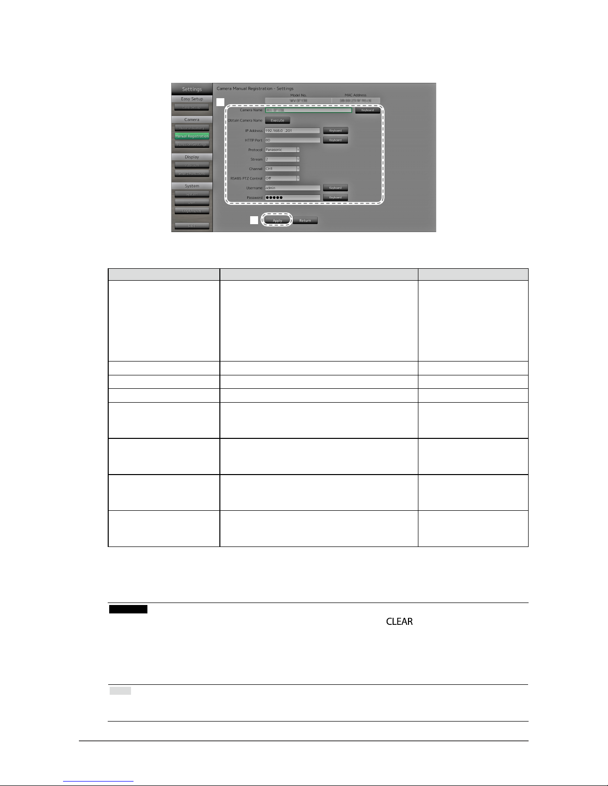
Chapter 2 Conguring from the monitor screen
3. Select “Settings”.
The network camera setting screen is displayed.
4
5
4. Congure the items.
For setting details, contact your system administrator.
Item Detail Setting range
Camera Name Enter the camera name. When you select
"Execute" for Obtain Camera Name, the camera
automatically obtains the camera name.
• Panasonic network camera: Camera title
• Network camera compatible with the “ONVIF”
protocol: Camera model number, manufacturer
name, etc.
Alphanumeric characters
(up to 24 characters)
IP Address Enter the network camera IP address. 0.0.0.0 to 255.255.255.255
HTTP Port Enter the network camera HTTP port number. 1 to 65535
Protocol Select the protocol for controlling the camera. ONVIF/Panasonic
Stream
*1
Set the number of the stream for delivering
camera images. Select a stream supported by the
connected network camera.
1 to 4
Channel
*1
Select the channel of the analog encoder. Set to
"1" if the network camera does not support the
channel function.
1 to 4
RS485 PTZ Control Controls the brightness, automatic focus
adjustment, pan, tilt and zoom for devices that are
connected to the camera through a RS485 cable.
On/Off
Username, Password Enter the username and password to use when
accessing network cameras.
Alphanumeric characters
and symbols
(up to 32 characters)
*1 Cannot be set if using a network camera compatible with the “ONVIF” protocol.
5. Select “Apply”.
The setting complete screen is displayed. Select “OK”.
Attention
• If you want to change the set values using the remote control, press the button, then enter the values
(for details see “To enter characters” (page 10)).
• Depending on the network camera type, the “Model No.” displayed on the setting screen may differ from
when the camera is discovered automatically and when it is registered manually.
• Only set “RS485 PTZ Control” to “On” when connecting an external device to the network camera using a
RS485 cable.
Note
• With manual registration, network settings of a camera cannot be changed. When changing the network
settings of a camera, check the network camera’s manual.
Page 14

14
Chapter 2 Conguring from the monitor screen
●
To set network camera functions
Set the network camera functions from the monitor.
Procedure
1. Select “Function Settings”.
Displays current
settings.
1
2
3
2. Select the network camera to congure at “Camera Name”.
3. Select a function.
The setting screen for the selected function is displayed.
Camera Information Display
Select to display or not display the camera information and time of the network camera settings on
the camera images.
Attention
• Cannot be set if using a network camera compatible with the “ONVIF” protocol.
2
1
1. Congure the items.
Item Detail Setting range
Camera Information Display Set whether or not to display camera information. On/Off
Time Display Set whether or not to display the time. 12h/24h/Off
Display Position Set the display position of the camera information
and time.
Upper Left/Upper Right/
Lower Left/Lower Right
2. Select “Apply”.
The setting complete screen is displayed. Select “OK”.
Page 15

15
Chapter 2 Conguring from the monitor screen
Clock Settings
1. Synchronizes the time of the network camera with the time of the monitor.
Select “Execute” to synchronize the clock.
Video Settings
Set the Image Quality of transmitted images for the network camera.
Note
• This product supports H.264 and MJPEG (ONVIF only) video compression formats.
Attention
• When devices such as recorders are connected to a network camera, the display and recording of such
devices may be affected.
WhenusingaPanasonicnetworkcamera
2
1
Page 16

16
Chapter 2 Conguring from the monitor screen
1. Congure the items.
Item Detail Setting range
Aspect Ratio Set the H.264 aspect ratio.
*1
Camera imaging mode
Resolution Set the H.264 resolution. According to the camera specication
Refresh Interval Set the refresh interval
*2
of H.264 images.
0.2s/0.33s/0.5s/1s/2s/3s/4s/5s
Transmission Priority Set the transmission mode of H.264 images.
Constant Bit Rate/Frame Rate/Best
Effort
Frame Rate (When the mode is set to “Frame Rate” at
“Transmission Priority”.)
Set the frame rate (image update interval) of
H.264 images.
*3
1fps/3fps/5fps/7.5fps/10fps/12fps/
15fps/20fps/30fps
Bit Rate (Max.) Set the maximum H.264 image bit rate.
64kbps/128kbps/256kbps/384kbps/
512kbps/768kbps/1024kbps/
1536kbps/2048kbps/3072kbps/
4096kbps/8192kbps/
Bit Rate (Min.) (When the mode is set to “Best Effort” for
“Transmission Priority”.)
Set the minimum H.264 image bit rate.
64kbps/128kbps/256kbps/384kbps/
512kbps/768kbps/1024kbps/
1536kbps/2048kbps/3072kbps/
4096kbps/8192kbps/
Image Quality (When the mode is set to “Constant Bit Rate”
or “Best Effort” for “Transmission Priority”.)
Set the H.264 image quality.
Low (prioritize motion)/Normal/Fine
(prioritize image quality)
*1 When “1920” is selected for “Resolution”, the aspect ratio is xed to 16:9. The aspect ratio cannot be set
when the network camera “Stream” is set to a value other than “1”.
*2 For H.264 images, the differential data between the full screen frame data and previous frame are sent
periodically. “Refresh Interval” refers to the interval for sending these full screen frame data. Shortening
this interval improves the stability of image quality but also increases the load on the network. “Refresh
Interval” refers to the interval at which the full screen data is transmitted. Shortening this interval improves
the image quality but also increases the load on the network.
*3 The shorter the interval, the shorter the update interval and the smoother the display, but also the larger the
load on the network.
2. Select “Apply”.
The setting complete screen is displayed. Select “OK”.
Attention
• To display the multicast stream of Panasonic network cameras, congure multicast on the camera.
• When you change the “Aspect Ratio”, the camera imaging mode will be changed. Depending on the imaging
mode, the image quality of other recording devices or display devices may be impacted. Check the impact of
changes to the imaging mode before conguring the settings.
Page 17

17
Chapter 2 Conguring from the monitor screen
ONVIFProleS-compatiblenetworkcameras
2
1
1. Congure the items.
Item Detail Setting range
Media Prole Select the ONVIF image prole. EIZO_Prole/camera prole
Encoder Select the encoder settings of ONVIF images. According to the camera specication
Compression Format Select compression format of ONVIF images. H.264/MJPEG
Resolution Set the resolution of ONVIF images. According to the camera specication
Frame Rate Set the frame rate (image update interval) of
ONVIF images.
1 to 30 fps
Encoding Interval Set the encoder interval of ONVIF images. According to the camera specication
Bit Rate (Max.) Set the maximum ONVIF image bit rate. 0 to 8192 kbps
Video Quality Set the ONVIF image quality. The higher the
value, the higher the image quality.
According to the camera specication
GOV Length*
1
Set the I-frame interval of ONVIF images. According to the camera specication
H.264 Prole*
1
Select a H.264 standard prole. Baseline/Main/Extended/High
Transmission Mode Select the transmission format of ONVIF
images.
Unicast/Multicast
Multicast Address*
2
Set the multicast address for multicast
transmission of ONVIF images.
224.0.0.0 to 239.255.255.255
Multicast Port*
2
Set the multicast port number for multicast
transmission of ONVIF images.
1024 to 65534 even numbers only
Multicast TTL*
2
Set the network TTL value for multicast
transmission of ONVIF images.
According to the camera specication
*1 Displays when “H.264” is selected in “Compression Format”.
*2 Displays when “Multicast” is selected in “Transmission Mode”.
2. Select “Apply”.
The setting complete screen is displayed. Select “OK”.
Attention
• Depending on the network camera type, some set values may not be reected. Check the specications of
the camera.
• When changes are made to the image quality settings such as resolution, this may impact on the image
quality of other recording devices and display devices using the same ”Encoder”. Check the impact of
changes to the image quality settings before conguring the settings.
Page 18

18
Chapter 2 Conguring from the monitor screen
Preset
Preset the shooting position and adjustment status of the network camera.
2
1
3
Displays images of the selected camera.
1. Select the number (1 to 256) to set for “Preset No”.
2. Congure the items.
Item Detail Setting range
Brightness Adjust the network camera brightness. -
Focus Adjust the network camera focus. -
Zoom Adjust the network camera display magnication. Position Adjust the network camera shooting position (pan/tilt). -
3. Select “Register (Home)” for registering the selected number as the home position. For all other
registrations, select “Register”.
The setting complete screen is displayed. Select “OK”.
Attention
• Depending on the type of the network camera you are using, some functions may not be available.
• Depending on the network camera type, it may not be possible to register the brightness and focus settings.
Note
• After the setting is registered, the number displayed at “Preset No.” changes from “Not Registered” to “Home”
or “Registered”.
• To clear a setting, select the number to clear at “Preset No.” and then select “Delete”. The data set for the
number is deleted and the number status returns to the unregistered state.
Page 19

19
Chapter 2 Conguring from the monitor screen
Other
Attention
• Cannot be set if using a network camera compatible with the “ONVIF” protocol.
2
1
1. Congure the items.
Item Detail Setting range
Pan/Tilt-ip Turn on/off the pan/tilt-ip function*1. On/Off
Upside-down
*2
Turn on/off the network camera upside down
function.
On/Off
Indicator Turn on/off the network camera Indicator. On/Off
*1 The pan/tilt-ip function reverses the pan/tilt direction automatically at high-speed when the network
camera reaches the movement endpoint. This function allows the user to make pan/tilt operations without
paying attention to movement endpoints.
*2 Check the network camera installation specications before using the upside down function. Depending
on the network camera type, it may not be possible to install the camera upside down even when the
camera supports the upside down function.
2. Select “Apply”.
The setting complete screen is displayed. Select “OK”.
3
Page 20

20
Chapter 2 Conguring from the monitor screen
2-4. Setting Display Positions of Camera Images
Set the display position for images from the network camera.
Procedure
1. Select “Position”.
Indicates the
display positions
on the monitor
screen.
1
2
3
2. Congure the items.
Item Detail Setting range
Position Select a position to display a camera image.
Set the network camera to the number of the
desired position for display.
-
Camera Name Display Select to display or not display the camera name
and time set on the monitor. (The camera name is
displayed on the upper left of the image.)
On/Off
Sequence Interval Set the interval for changing over the screen during
sequential display.
5s to 60s
Aspect Ratio Mode Set which aspect ratio to apply when the aspect
ratio of the video delivered from the network
camera and the aspect ratio of the monitor image
display area differ.
Full/Aspect
3. Select “Apply”.
The setting complete screen is displayed. Select “OK”.
Attention
• All registered network cameras must be congured. A network camera can only be set for one display position.
When there are incorrect settings, “Apply” cannot be selected.
Note
• If it takes a while for images to be displayed during sequential display, set a higher value for “Sequence Interval”.
Page 21

21
Chapter 2 Conguring from the monitor screen
2-5. Setting Smart Functions
Set Smart Functions for images from each camera.
Procedure
1. Select “Smart Functions”.
Displays current
settings.
1
2
4
3
Displays images of the selected network camera.
2. Select the network camera to congure at “Camera Name”.
Attention
• For 1 Screen or 4 Screens layouts the settings of each network camera are applied. For 8 Screens, 9
Screens or 16 Screens layouts, the “17_Full Screen” settings are applied to all screens and the settings of
each network camera are not applied.
3. Congure the items.
Item Detail Setting range
Mode Select the display mode to apply to the images of
the selected network camera.
Set to “DAY” to apply a mode suitable for general
images.
Set to “NIGHT” to apply a mode suitable for
monochrome images such as images taken at
night.
DAY/NIGHT/Off
Smart Resolution Adjusts the perceived resolution of the images
so that the blurs are reduced and images are
displayed vividly and clearly.
1 to 5/Off
Smart Insight Makes dark areas of images visible by analyzing
the image and correcting the brightness for each
pixel. It is effective for images with dark area that
are less visible and for bright environments.
1 to 5/Off
Noise Reduction Reduces the amount of block noise that occurs due
to video compression.
On/Off
4. Select “Apply”.
The setting complete screen is displayed. Select “OK”.
Page 22

22
Chapter 2 Conguring from the monitor screen
2-6. ConguringSystemSettings
Set the date, time and network information for this product.
Procedure
1. Select “System”.
Displays current
settings.
(E.g. software version)
1
2
2. Select a setting.
The setting screen for the selected setting is displayed.
Date and Time
Set the current date and time.
1
2
1
2
3
1. Select “Date/Time Display Setting” or “Clock Setting”.
2. Congure the items.
Item Detail Setting range
Date/Time Display Settings Set the date display format,
time display format, and time
zone (time difference between
GMT
*1
).
Date Format yyyy/mm/dd, Mmm/dd/yyyy,
dd/Mmm/yyyy, mm/dd/yyyy,
dd/mm/yyyy
Time Format 24h/12h
Time Zone GMT-12:00 to GMT+14:00
Clock Setting Set the current time. 2010/1/1 0:00 to 2035/12/31 23:59
*1 Greenwich Mean Time
3. Select “Apply”.
The setting complete screen is displayed. Select “OK”.
Note
• If the main power switch is turned off or the power cord is unplugged for one week or longer, the monitor’s
time and date will no longer be displayed accurately. In such a case, set the date and time again.
Page 23

23
Chapter 2 Conguring from the monitor screen
Summer Time (DST)
Apply or cancel the summer time setting (DST).
1
2
1. Congure the items.
Item Detail Setting range
Summer Time (DST) Applies or cancels the summer time setting.
Set to “On” to apply to summer time immediately.
Set to “Off” to not apply to summer time.
Set to “Auto” to apply to summer time automatically
during the period designated by the start/end dates
and times.
On/Off/Auto
2. Select “Apply”.
The setting complete screen is displayed. Select “OK”.
Page 24

24
Chapter 2 Conguring from the monitor screen
Network
Set network information.
2
3
1
1
1
2
2
1. Select “Network Settings”, “DNS Settings” or “NTP Settings”.
2. Congure the items.
Item Detail Setting range
Network Settings Select the IP address setting method. IP Setting Method DHCP/Manual
Setting
If “Manual Setting” is selected, set the IP
address, subnet mask and gateway.
IP Address, Subnet
Mask, Gateway
*1
0.0.0.0 to
255.255.255.255
DNS Settings Set the DNS.
(When “IP Address” of “Network Settings” is set
to “Manual”.)
DNS Auto/Manual
If you selected “Manual”, set the primary server
address and the secondary server address.
Primary Server
Address,
Secondary Server
Address
0.0.0.0 to
255.255.255.255
NTP Settings Set whether or not to use an NTP server. NTP On/Off
If you selected “On”, set the NTP server
address.
Server Address Alphanumeric
characters and
symbols
*1 If your network environment does not include a gateway, you do not need to set the “Gateway” address.
Use the default setting as is, or set as “0.0.0.0”.
3. Select “Apply”.
The setting complete screen is displayed. Select “OK”.
Page 25

25
Chapter 2 Conguring from the monitor screen
Communication Settings
The communication settings are used to congure the web interface function, detection of
communication errors, and so on.
1
2
1. Congure the items.
Item Detail Setting range
Communication speed Sets the communication speed between the monitor and
network hub.
100Mbps Half duplex,
100Mbps Full duplex,
1000Mbps Full duplex
Communication Error
Detection
You can set the following as the message to be displayed
when receipt of image data stops.
Comm. Error Detection On:
Within several seconds after receipt of image data stops,
an alert message in a red box will appear on the live
image screen. When communication resumes, the alert
is cleared and the image is displayed again.
Comm. Error Detection Off:
When approx. 20 seconds have elapsed after receipt of
image data stops, a communication error message will
ap pe ar.
On/Off
Web Interface You can operate and congure the monitor from your web
browser over the network.
On/Off
Web Interface Port Sets the port of the web interface. 1 to 65535
2. Select “Apply”.
The setting complete screen is displayed. Select “OK”.
Page 26

26
Chapter 2 Conguring from the monitor screen
Other
1
2
1. Congure the items.
Item Detail Setting range
Language Set the display language of the menu and the setting
screen.
日本語
/English/Deutsch
Quick Start Set the status of the system when turned off.
When set to “On”, part of the system remains running.
When set to “Off”, the system is shut down completely.
By setting to “On”, the startup time for this product can be
reduced (approx. 10 seconds). However, do not turn off
the main power of the monitor when Quick Start is set to
“On” because part of the system remains running.
On/Off
Key Lock Locks operations by the buttons on the front of the
monitor.
On/Off
Logo Set whether to display/hide the EIZO logo when the
power is turned on
*1
.
On/Off
Power Indicator Set whether to turn of or off the power indicator (blue)
while the monitor is on.
On/Off
*1 The rotating bar indicating that the system is starting up cannot be hidden.
2. Select “Apply”.
The setting complete screen is displayed. Select “OK”.
Page 27

27
Chapter 2 Conguring from the monitor screen
Initialization
Initialize the system.
1
1. Select “Execute” for “Initialization”.
All settings are returned to default except for system logs, operation logs, the current time, time zone and
summer time settings.
Restart
Restart the system.
1. Select “Execute” at “Restart”.
Settings Data Migration
You can save the settings data to a USB storage device and load the data.
Load Settings Data
4
3
2
5
1. Connect a USB storage device to the USB downstream port of the monitor.
2. Select the settings data le.
3. Enter the password.
The password is blank by default. Set the password as necessary.
4. Select “Execute”. The settings data are loaded.
5. Select “Run” for “Remove USB Storage”.
When the Removing Complete screen is displayed, select “OK”.
6. Remove the USB storage device.
Attention
• The settings data include the IP address of the monitor. Change the IP address of the monitor if loading
settings data from another monitor.
Page 28

28
Chapter 2 Conguring from the monitor screen
Save Settings Data
1. Connect a USB storage device to the USB downstream port of the monitor.
2
4
3
2. Enter the password.
The password is blank by default. Set the password as necessary.
3. Select “Execute”. The settings data are saved.
4. Select “Run” for “Remove USB Storage”.
When the Removing Complete screen is displayed, select “OK”.
5. Remove the USB storage device.
Attention
• Some of the settings cannot be saved.
• If you forget the password that you specied when saving the data, you will no longer be able to load the settings.
Note
• Saved le name: Backupyyyymmdd.duraconf (yyyymmdd is the save date)
Page 29

29
Chapter 2 Conguring from the monitor screen
Software Update
You can select update les from the File Selection screen, and can both upgrade or downgrade
software.
1. Download the update le from the EIZO website (http://www.eizoglobal.com), and save it to a USB
storage device.
2. Connect a USB storage device to the USB downstream port of the monitor.
The File Selection screen is displayed.
3
4
3. Select the update le.
4. Select “Execute”.
5. The message saying “You must restart the system to update the software. Remove the USB
storage and restart.” appears.
Remove the USB storage device.
6. Select “Restart” to restart the system.
The software is updated.
Attention
• Do not turn off the power while the software is being updated.
• You cannot operate the remote control and
and buttons on the front of the monitor while the
software is being updated.
• The following USB storage devices can be used with this product.
- USB 2.0 standard ash drives
- Supported format: FAT32
• Do not connect multiple USB storage devices simultaneously.
Note
• When you restart your system, a message indicating the success or failure of the software update will appear.
The message will clear automatically after 60 seconds if “OK” is not clicked. However, this message will not
appear if you do the update through your web browser.
Page 30

30
Chapter 2 Conguring from the monitor screen
Troubleshooting
Use this function when this product does not operate normally, such as when a connection cannot be
established with a network camera or a communication error occurs. The network status can be
checked using communication commands and past error contents can be checked by displaying the
system log. In addition, system log data can be saved to a USB storage device.
Checking network connection status
1
2
3
Displays the
connection check
results.
1. Select “Connection Conrmation”.
2. Select the network camera to check the network connection of for “Camera Name”.
3. Select “Run” for “ping” or “traceroute”.
Results are displayed in the area on the right side of the screen.
Displaying the system log
1
2
3
Displays the log.
1. Select “System Log”.
2. Select the date (year/month/day) to display the log data of.
3. Select “Run” for “Display”.
The log data is displayed in the area on the right side of the screen.
Page 31

31
Chapter 2 Conguring from the monitor screen
Saving system log data
1. Connect a USB storage device to the USB downstream port on the back of the monitor.
USB downstream port
2
3
4
Displays the data
storage status.
5
2. Select “System Log”.
3. Select the date (year/month/day) of the log data to display.
4. Select “Run” for “Save to USB Storage”.
Data saving starts and a “Saving” message is displayed in the display area on the right side of the screen.
When the saving complete screen is displayed, select “OK”.
5. Select “Run” for “Remove USB Storage”.
When the removing complete screen is displayed, select “OK”.
6. Remove the USB storage device.
Attention
• The following USB storage devices can be used with this product.
- USB 2.0 standard ash drives
- Supported format: FAT32
• Do not connect multiple USB storage devices simultaneously.
Page 32

32
Chapter 2 Conguring from the monitor screen
2-7. Setting User Information
Register, change or delete information (username, user level and password) on users that access this
product.
Attention
• User information can be registered for up to 10 users. User information for a new user cannot be registered when
there are already 10 users registered.
• Duplicate usernames cannot be registered.
• At least one user with a user level of “ADMIN” must be registered.
• You can use alphanumeric characters for the username, however, the following character is not allowed: “ : “.
Note
• There are three user levels: “ LIVE”, “CAMERA CONTROL” and “ADMIN”.
The operable range of this product differs by each level.
(√: Operable, -: Inoperable)
Operation
Level
Menu
display
Layout
change
over
Page
change
over
Smart
Functions
on/of f
Login
operation
Camera
control
System
settings
LIVE √ √ √ √ √ - CAMERA CONTROL √ √ √ √ √ √ ADMIN √ √ √ √ √ √ √
• The following user information is set by default:
- Username: “admin”
- Password: “admin”
- User Level: “ADMIN”
• User information settings can be returned to default settings by the following procedure. Use this feature, for
example, when you have forgotten the registered user information.
1. Press
on the remote control to turn off the monitor.
2. Press the buttons on the remote control in the following order (press the next button within ve seconds).
→ → → → → →
When the reset conrmation screen is displayed, select “Execute”.
User information is cleared and the settings are returned to the default settings.
●
To register new user information
Procedure
1. Select “User”.
1
2
4
3
2. Select “New User Registration”.
3. Set user information.
4. Select “Register”.
The setting complete screen is displayed. Select “OK”.
Page 33

33
Chapter 2 Conguring from the monitor screen
●
To change user information
Procedure
1. Select “User”.
1
2
4
3
2. Select “Change/Delete User Information”.
3. Set user information.
4. Select “Change”.
The setting complete screen is displayed. Select “OK”.
●
To delete user information
Procedure
1. Select “User”.
1
2
4
3
2. Select “Change/Delete User Information”.
3. Select the user to delete at “Username”.
4. Select “Delete”.
The setting complete screen is displayed. Select “OK”.
Page 34

34
Chapter 2 Conguring from the monitor screen
2-8. Displaying Operation Logs
Operations of this product are recorded on logs. Past operation results can be checked by displaying the
log. Also, log data can be saved to a USB storage device.
Note
• The following data are recorded on the log:
- Login information: The names of users who logged in to the system
- Camera operation results: Name of operated camera, operation details, operation results
- Date, time and details of changes conrmed by selecting “Apply” on setting screens
• Logs older than two months are automatically deleted at 04:00:00 AM on the rst day of every month.
●
To display log data
Procedure
1. Select “Log Display”.
1
2
3
Displays the log.
2. Select the date (year/month/day) to display the log data of.
3. Select “Run” for “Display”.
The log data is displayed in the area on the right side of the screen.
Page 35

35
Chapter 2 Conguring from the monitor screen
●
To save log data
Procedure
1. Connect a USB storage device to the USB downstream port on the back of the monitor.
USB downstream port
2. Select “Log Display”.
2
3
4
Displays the data
storage status.
5
3. Select the date (year/month/day) of the data to save.
4. Select “Run” for “Save to USB Storage”.
Data saving starts and a “Saving” message is displayed in the display area on the right side of the screen.
When the saving complete screen is displayed, select “OK”.
5. Select “Run” for “Remove USB Storage”.
When the removing complete screen is displayed, select “OK”.
6. Remove the USB storage device.
Attention
• The following USB storage devices can be used with this product. (This does not guarantee operation of the
USB storage devices given below.)
- USB 2.0 standard ash drives
- Supported format: FAT32
• Do not connect multiple USB storage devices simultaneously.
Page 36

36
Chapter 3 Conguring from a Web Browser
Chapter 3 ConguringfromaWebBrowser
This product allows you to congure and operate network cameras from your web browser.
The setting screen contains the Monitor Settings and live image screen settings.
Note
• To congure from the monitor screen, see ”Chapter 2 Conguring from the monitor screen” (page 8).
Attention
• It is recommended you use Internet Explorer 11 as your web browser.
• If you congure settings from a web browser, you will need to start up the monitor.
• You cannot display the web interface in your web browser when the monitor web interface is disabled in the settings.
(For details, see “Network Settings” (page 55)).
3-1. BeforeConguration
To congure settings from a web browser, you need to log in from the web browser you are using. Login
is allowed only when the level of the user accessing the product is ADMIN.
Procedure
1. Press
on the front of the monitor or on the remote control.
The power indicator lights up blue and the live image screen is displayed.
(For information on the live image screen, refer to the Instruction Manual.)
2. Display the web browser on your PC.
3. Enter the following address to access.
Address: http://Address of the monitors/ui
*1
*1 The default address for access is http ://192.168.0.150/ ui.
The login screen is displayed.
4. Enter a username and a password.
5. Select “Login”.
Displays the Monitor Settings.
Note
• The following user information is set by default:
- Username: “admin”
- Password: “admin”
- User Level: “ADMIN”
• For information on user settings, see “2-7. Setting User Information” (page 32).
• It is recommended that you log out after completing the setup, so as to prevent a third party from operating
the network camera or altering the settings. Exit the web browser.
Page 37

37
Chapter 3 Conguring from a Web Browser
3-2. Setting Screen
The setting screen contains the Monitor Settings and live image screen settings.
The Monitor Settings are used for various settings such as basic information, network camera registration
and monitor system settings. The live image screen settings are used for conguring the display, such as
changing the live image screen layout.
●
Basic Operations
To select a setting item
• Click a setting item.
When you select a setting item, it will be displayed in green. In the case of a list box, when you
select a list item, it will be displayed in green.
To apply a setting item
• Click “Apply” or “Register”.
A “Setting Complete” or “Setting Failed” message is displayed. Click “OK” as required.
To exit the web browser
• Click
in the web browser. This exits the browser.
Note
• If auto discovery is in progress on the monitor, or the setting dialog box is displayed in the browser, operations
in the browser will not be accepted and a busy status message will be displayed. Click “OK” to congure the
settings again.
Page 38

38
Chapter 3 Conguring from a Web Browser
3-3. Basic Information
Display lists of the various settings acquired from the monitor.
●
System Status
Current Status
Displays the current status of the monitor. Also, you can transition the status of the monitor by changing the
selection status.
1. Click ▼ next to “New Status” to select the status from the displayed list.
2. Click “Apply”.
The screen transitions to the selected state.
The following statuses are displayed.
Item Status
Live Image Screen Transition to “Live Image Screen Settings”
HDMI Port Display HDMI port display status, without screen transition
Quick Shutdown Transition to Quick Shutdown status
Attention
• When Quick Shutdown is selected:
A setting error occurs and a “Quick Start is set to OFF. Run after setting Quick Start to ON.” message is
displayed.
Page 39

39
Chapter 3 Conguring from a Web Browser
Brightness setting
Adjusts the brightness of the monitor screen.
1. Click the brightness setting ( , ).
Changes the brightness of the monitor screen.
Note
• You can change the Brightness on the monitor screen in the same manner as when pressing the
(
,
) buttons on the remote control. A “Setting Complete” or “Setting Failed” message will
not display after changing the brightness.
●
Camera and Display Position/Date and TimeSettings/Network
Settings/Communication Settings
Displays the current settings status of the monitor. When conguring settings, click the link for the
item name under an item. The screen transitions.
Attention
• For the basic information, the setting values for items other than the system status cannot be changed. When
conguring an item, click the link for the item name under each item. The screen transitions to the applicable
setting item screen.
Page 40

40
Chapter 3 Conguring from a Web Browser
3-4. Setting Network Cameras
“Camera Registration” is used to display a list of the network cameras currently registered for a monitor.
You can add or change network cameras, and reect network camera information, etc., onto the monitor.
Attention
• You can only change network cameras that are registered.
• This cannot be used to set network camera functions. For information on setting network camera functions, see
“Chapter 2 Conguring from the monitor screen” (page 8).
●
To automatically detect cameras
Discover network cameras on the network automatically and register them to the system.
Attention
• Only the network cameras installed in the same subnet as the monitor are detected. If a network camera is
installed in a different subnet, the camera must be registered manually (see “To manually register network
cameras” (page 12)).
• For information on “Easy Setup”, refer to the Setup Manual.
Note
• The remaining number of cameras that can be added for registration is clearly indicated at the top of the
camera detection screen.
Procedure
1. Select “Camera Registration”.
A screen displaying a list of the camera registration information appears.
2. Select “Add”.
Page 41

41
Chapter 3 Conguring from a Web Browser
3. Select “Auto Discovery”.
A “Camera detection will start” dialog box appears.
4. Select “OK”.
A “Searching” dialog box appears, and the detected cameras are displayed in the list of candidates for
adding.
Note
• There is a web page link in the web page eld of the list of detected cameras. When you click a link, a
camera web page will open in a separate window. (Address: http://(IP address):(HTTP port))
• If there are zero candidates in camera detection, nothing will display.
• If “Cancel” is selected during camera detection, a list of cameras detected up to the time of canceling will
be displayed.
5. Select a camera to be added from the list of candidates, and select “Add”.
6. Select “Return”.
Returns to the camera registration information list screen in step 1.
7. Select “Apply”.
A setting conrmation dialog box appears.
8. Select “OK” or “Cancel” as necessary.
Page 42

42
Chapter 3 Conguring from a Web Browser
●
Reading CSV Files
The CSV le describing the camera candidates to be added can be read, and the cameras can be set
as candidates for detection.
Procedure
1. Select “Camera Registration”.
A list of camera registration information appears.
2. Select “Add”.
3. Select “Read from CSV le”.
A le dialog box opens.
4. Select the CSV le that describes the camera information, and select “Open”.
A list of the candidate cameras appears.
Note
• Up to 255 candidate cameras can be read.
• The CSV les that can be read are as follows.
- CSV les that are exported from the monitor or browser
- CSV les created by the user
• For details on how to export CSV les, refer to “Save Camera Information” (page 48).
• When a user creates a CSV le, the following rules apply.
- In line 1, enter the following as the item line: “CameraName, Protocol, IPAddress, HttpPort, UserName,
PassWord”.
- The columns are in random order.
- Input of the “UserName, PassWord” values is user-dened.
- Only the specied string can be read for an item name.
Page 43

43
Chapter 3 Conguring from a Web Browser
5. Select a camera to be added from the list of candidates, and select “Add”.
6. Select “Return”.
Returns to the camera registration information list screen in step 1.
7. Select “Apply”.
A setting conrmation dialog box appears.
8. Select “OK” or “Cancel” as necessary.
●
Adding a Camera
You can add a camera to the camera registration information list by using the auto detection function
and Read from CSV le function.
Procedure
1. Select “Camera Registration”.
A screen displaying a list of the network camera registration information appears.
2. Select “Add”.
The network cameras subject to adding are reected onto the camera registration information list.
(For details, see “To automatically detect cameras” (page 40) and “Reading CSV Files” (page 42))
Page 44

44
Chapter 3 Conguring from a Web Browser
3. Select “Return”.
Returns to the camera registration information list screen in step 1.
4. Select a camera to be added from the list of candidates, and select “Add”.
5. Select “Apply”.
A setting conrmation dialog box appears.
6. Select “OK” or “Cancel” as necessary.
Page 45

45
Chapter 3 Conguring from a Web Browser
●
Changing Camera Information
You can change the contents of the registered information for cameras in the camera registration
information list.
Attention
• If multiple selections are made for registration information of a network camera to be changed, the “Change”
button will be disabled.
1. Select “Camera Registration”.
A screen displaying a list of the camera registration information appears.
2. Check the number of the camera to be changed.
3. Select “Change”.
A “Camera Information Settings” dialog box appears.
Note
• When a registered camera is selected, a dialog box describing the applicable camera information
appears. When an unregistered display position is selected, a dialog box with “Panasonic” selected in the
“Protocol” item appears.
Item Detail Setting range
Camera Name Can use alphanumeric characters, kana and kanji 0 to 24 characters
IP Address If a new camera, leave blank 0.0.0.0 to 255.255.255.255
Page 46

46
Chapter 3 Conguring from a Web Browser
4. Set the changes, and select “OK”.
Returns to the camera registration information list screen in step 1.
5. Select “Apply”.
A setting conrmation dialog box appears.
6. Select “OK” or “Cancel” as necessary.
Note
• The following message is displayed when acquisition of the “Obtain Camera Name” and “Obtain Prole”
information fails. Obtain the information again.
Page 47

47
Chapter 3 Conguring from a Web Browser
●
Deleting Camera Information
You can delete the contents of the registered information for cameras.
1. Select “Camera Registration”.
A screen displaying a list of the camera registration information appears.
2. Check the number of the camera to be deleted.
3. Select “Delete”.
A setting conrmation dialog box appears.
4. Select “OK” or “Cancel”.
5. Select “Return”.
Returns to the screen that displays a list of the camera registration information.
6. Select “Apply”.
A setting conrmation dialog box appears.
7. Select “OK” or “Cancel” as necessary.
Page 48

48
Chapter 3 Conguring from a Web Browser
●
Save Camera Information
You can save the information registered in the camera registration information list to a CSV le.
When you select “Save Camera Information”, a CSV le describing the camera information displayed
in the information list is exported.
File name: fdf2304wip_CameraInfo_yyyymmdd.csv
(yyyymmdd is the computer date and time.)
3-5. Setting Display Positions of Camera Images
You can congure settings such as the display positions of network cameras, and displaying camera
names in the live image screen.
1. Select “Display” in the “Monitor Settings”.
The screen transitions to the Display Position Setting screen. A link for each setting item that can be
congured in “Display” is located at the top of the screen.
2. Select each setting item.
The screen transitions to the selected setting item.
Page 49

49
Chapter 3 Conguring from a Web Browser
●
Setting Display Positions
Set the positions for displaying network camera images.
You can switch the display positions of the source and destination camera images by dragging and
dropping the camera within the page.
Attention
• All of the display positions of registered network cameras can be set.
Procedure
1. Select “Display Position Settings”.
The “Display Position Settings” screen appears.
Each of the outer frames containing the number on the page are the camera display position
*1
, and the inner
squares for the camera display position are the camera name
*2
to be displayed.
*1
*2
2. Select the display position layout from the list.
Select the layout from the list box. The settings screen changes in accordance with the selected layout.
Note
• When you select a layout in the list box, the display in the Page changes to the selected state. You can set
the display status while imaging.
• The initial display position when the screen is transitioned is the display position currently set in the
monitor.
• You can switch the camera names in the inner squares by dragging and dropping them between the
respective pages.
Page 50

50
Chapter 3 Conguring from a Web Browser
3. Drag a camera name and drop it on the position number where you want to display it.
The display positions of the source and destination camera images are switched.
Example) 4 screen layout
1. Drag display position 1 on Page 1 and drop it at display position 5 on page 2.
2. The display position 1 and display position 5 cameras are switched.
3. Only the camera name in the inner square is moved, without moving the display position of
the camera image.
4. Select “Apply”. The display positions of camera images are updated.
When you select “Reset”, the information of the setting being changed is discarded, and becomes the
current monitor display settings.
Note
• A camera web page link is embedded in frames that have been allocated a camera name. When you click
it, a camera web page will open in a separate window (see “Adding a Camera” (page 43)).
●
Other Display Settings
Set the items to be displayed in camera images.
Procedure
1. Select “Other Display Settings”.
The “Other Display Settings” screen is displayed.
2. Congure the items.
Item Detail Setting range
Camera Name Display Select to display or hide the camera name set on the
monitor. (The camera name is displayed on the upper left
of the image.)
On/Off
Sequence Interval Set the interval for changing over the screen during
sequential display.
5 to 60 seconds
Aspect Ratio Mode Set which aspect ratio to apply when the aspect ratio of the
video delivered from the network camera and the aspect
ratio of the monitor image display area differ.
Full/Aspect
Page 51

51
Chapter 3 Conguring from a Web Browser
●
Setting Smart Functions
Set Smart Functions for images from each camera.
Attention
• Information such as camera name will be displayed as a blank row for display positions that have not been
allocated a camera. Each list box becomes invalid and will not be displayed.
Procedure
1. Select “Smart Functions”.
The “Smart Functions” screen appears.
2. Set the camera of the applicable display position.
Attention
• For 1 Screen or 4 Screen layouts the settings of each network camera are applied. For 8 Screen, 9
Screen or 16 Screen layouts, the “Full Screen” settings are applied to all screens and the settings of each
network camera are not applied.
3. Congure the items.
Item Detail Setting range
Mode Select the display mode to apply to the images of the selected
network camera.
Set to “DAY” to apply a mode suitable for general images.
Set to “NIGHT” to apply a mode suitable for monochrome
images such as images taken at night.
DAY/NIGHT/Off
Smart Resolution Adjusts the perceived resolution of images. Reduces blurring
and displays images vividly and clearly.
1 to 5/Off
Smart Insight Makes dark areas of images visible by analyzing the image
and correcting the brightness for each pixel. This function is
effective when for instance viewing images with dark areas
that are not easily visible, or when using the monitor in a
bright environment.
1 to 5/Off
Block Noise Reduction Reduces the amount of block noise (noise from tessellated
images).
On/Off
4. Select “Apply”.
The setting complete screen is displayed. Select “OK”.
Page 52

52
Chapter 3 Conguring from a Web Browser
3-6. ConguringSystemSettings
Congure settings such as the date and time of this product, network settings, and maintenance.
Procedure
1. In the “Monitor Settings”, select “System”.
A link for each setting item that can be congured in the system settings is located at the top of the screen.
2. Select each setting item.
The screen transitions to the selected setting item.
●
Date and Time
You can set the current date and time, and set summer time.
1. Select “Date and Time”.
The “Date and Time” screen is displayed.
Page 53

53
Chapter 3 Conguring from a Web Browser
Date/Time Display Settings
Set the current date and time.
1. Congure the items.
Item Detail Setting range
Date/Time Display Settings Set the date display format, time display
format, and time zone (time difference with
GMT
*1
).
yyyy/mm/dd, Mmm/dd/yyyy,
dd/Mmm/yyyy, mm/dd/yyyy,
dd/mm/yyyy
Time Format 24h/12h
Time Zone GMT-12:00 to GMT+14:00
Procedure Manual/Synchronize with PC
Date and Time Set the current time. 2010/1/1 0:00 to 2035/12/31 23:59
*1 Greenwich Mean Time
2. Select “Apply”.
The setting complete screen is displayed. Select “OK”.
Note
• When “Synchronize with PC” is selected in “Procedure”, the current date and time setting information of the
computer is sent to the monitor and synchronized.
• If the main power switch is turned off or the power cord is unplugged for one week or longer, the monitor’s
time and date display will no longer be displayed accurately.
Page 54

54
Chapter 3 Conguring from a Web Browser
Summer Time (DST)
Apply or cancel the summer time setting (DST).
1. Congure the items.
Item Detail Setting range
Summer Time (DST) Applies or cancels the summer time setting.
Set to “On” to apply summer time immediately.
Set to “Off” to not apply summer time.
Set to “Auto” to apply summer time automatically during the
period designated by the start /end dates and times.
On/Off/Auto
2. Select “Apply”.
The setting complete screen is displayed. Select “OK”.
Page 55

55
Chapter 3 Conguring from a Web Browser
●
Network Settings
Set network information.
Attention
• When any one of the IP address settings/IP address/subnet mask/gateway is changed and “Apply” is
selected, the warning message “The network settings will be changed” is displayed. Select “OK” or “Cancel”
as necessary.
Also, when you select “OK” for the warning message, a message requesting that you access again appears.
1. In “System”, select “Network Settings”.
The “Network Settings” screen is displayed.
2. Congure the items.
Item Detail Setting range
Network Settings Select the IP address setting method. IP Setting Method DHCP/Manual Setting
If “Manual Setting” is selected, set the IP
address, subnet mask and gateway.
IP Address, Subnet
Mask, Gateway
*1
0.0.0.0 to
255.255.255.255
DNS Settings Set the DNS.
(When “IP Address” in “Network Settings”
is set to “Manual”.)
DNS Auto/Manual
If you selected “Manual”, set the primary
server address and the secondary server
address.
Primary Server
Address, Secondary
Server Address
0.0.0.0 to
255.255.255.255
NTP Settings Set whether or not to use an NTP server. NTP On/Off
If you selected “On”, set the NTP server
address.
Server Address Alphanumeric,
symbols
*1 If your network environment does not include a gateway, you do not need to set the “Gateway”. Use the
default setting as is, or set as “0.0.0.0”.
3. Select “Apply”.
The setting complete screen is displayed. Select “OK”.
Page 56

56
Chapter 3 Conguring from a Web Browser
●
Communication Settings
The communication settings are used to congure the web interface function, detection of
communication errors, and so on.
1. In “System”, select “Communication Settings”.
The “Communication Settings” screen is displayed.
2. Congure the items.
Item Detail Setting range
Communication
Speed
Set the communication speed between the monitor and
network hub.
100Mbps Half duplex,
100Mbps Full duplex,
1000Mbps Full duplex
Communication Error
Detection
You can set the following as the message to be displayed
when receipt of image data stops.
Communication Error Detection On:
Within several seconds after receipt of image data stops,
an alert message in a red box will appear on the live image
screen. When communication resumes, the alert is cleared
and the image is displayed again.
Communication Error Detection Off:
When approx. 20 seconds have elapsed after receipt of image
data stops, a communication error message will appear.
On/Off
Web Interface You can operate and congure the monitor from your web
browser over the network.
On/Off
Web Interface Port Sets the port of the web interface
*1
1 to 65535
*1 When the web interface is enabled, you can set the port.
3. Select “Apply”.
The setting complete screen is displayed. Select “OK”.
Attention
• When the web interface is disabled, you will not be able to congure the monitor settings from your web
browser. When the web interface is disabled and “Apply” is selected, the following warning message
appears.
Page 57

57
Chapter 3 Conguring from a Web Browser
●
Other System Settings
1. In “System”, select “Other System Settings”.
The “Other System Settings” screen appears.
2. Congure the items.
Item Detail Setting range
Language Set the display language of the menu and the setting
screen.
日本語
/English/Deutsch
Quick Start Set the status of the system when turned off.
When set to “On”, part of the system remains running.
When set to “Off”, the system is shut down completely.
By setting to “On”, the startup time for this product can be
reduced (approx. 10 seconds). However, do not turn off
the main power of the monitor when Quick Start is set to
“On” because part of the system remains running.
On/Off
Key Lock Locks operations by the buttons on the front of the
monitor.
On/Off
Logo Set whether to display/hide the EIZO logo when the
power is turned on
*1
.
On/Off
Power Indicator Set whether to turn of or off the power indicator (blue)
while the monitor is on.
On/Off
*1 The rotating bar indicating that the system is starting up cannot be hidden.
3. Select “Apply”.
The setting complete screen is displayed. Select “OK”.
Page 58

58
Chapter 3 Conguring from a Web Browser
●
Maintenance
Perform system initialization, restarts, and software updates.
1. In “System”, select “Maintenance”.
The “Maintenance” screen is displayed.
Initialization and Restart
Initialize the system
1. Select “Execute” for “Initialization”.
All settings are returned to default setting except for system logs, operation logs, the current time, time
zone and summer time settings.
2. The following message appears.
Select “OK” or “Cancel” in accordance with the response.
Page 59

59
Chapter 3 Conguring from a Web Browser
Restart the system
1. Select “Start” at “Restart”.
Restart the system.
2. The following message appears.
Select “OK” or “Cancel” in accordance with the response.
Page 60

60
Chapter 3 Conguring from a Web Browser
Software Update
You can both upgrade or downgrade the software.
1. In “System”, select “Maintenance”.
The screen transitions to “Software Update”.
2. Select “Browse”.
A le selection dialog box opens. Select the applicable le.
Attention
• The software will not be updated if a le is not selected, or a le other than an update le has been
selected.
• Perform software updates with the monitor screen displayed.
3. Select “Execute”.
The following message appears. Select “OK” or “Cancel” in accordance with the response.
4. Select “OK”.
The update process starts, and the following message appears.
5. Select “OK”. The software is updated.
Close the web browser, and wait 5 minutes before accessing again.
Note
• You can select update les from the File Selection screen, and can perform upgrading or downgrading of
software.
• When you restart your system, a message indicating the success or failure of the software update will
appear. The message will clear automatically after 60 seconds if “OK” is not selected. However, this
message will not appear if you do the update through your web browser.
Page 61

61
Chapter 3 Conguring from a Web Browser
3 -7. Setting User Information
Register, change or delete information (username, user level and password) on users that access this
product.
Note
• For details, see “2-7. Setting User Information” (page 32).
●
Adding User Information
Procedure
1. Select “User”.
The “User Settings” screen is displayed.
2. Select “Add”.
A dialog box for entering user information appears.
3. Set user information.
4. Select “OK”.
The setting complete screen is displayed. Select “OK”.
Page 62

62
Chapter 3 Conguring from a Web Browser
●
Changing User Information
Procedure
1. Select “User”.
2. Select the user to be changed from the “User List”.
3. Select “Change”.
A dialog box for entering user information appears.
4. Set user information.
5. Select “OK”.
The setting complete screen is displayed. Select “OK”.
Page 63

63
Chapter 3 Conguring from a Web Browser
●
To delete user information
Procedure
1. Select “User”.
2. Select the user to be deleted from the “User List”.
3. Select “Delete”.
4. A “Are you sure you want to delete user xxx?” conrmation dialog box appears. Select “OK”.
If you do not want to delete the user, select “Cancel”.
5. The setting complete screen is displayed. Select “OK”.
Page 64

64
Chapter 3 Conguring from a Web Browser
3-8. Displaying Operation Logs
Operations of this product are recorded on logs. Past operation results can be checked by displaying
operation logs. You can also display system logs.
Note
• The following data are recorded on the log:
- Login information: The names of users who logged in to the system
- Camera operation results: Name of operated camera, operation details, operation results
- Date, time and details of changes conrmed by selecting “Apply” on setting screens
• Logs older than two months are automatically deleted at 04:00:00 AM on the rst day of every month.
●
Displaying logs
Procedure
1. Select “Log Display”.
2. Select “Operation Log Display”.
The log data is displayed in the area at the bottom of the screen.
●
Displaying the system log
Procedure
1. Select “Log Display”.
2. Select “System Log Display”.
The log data is displayed in the area at the bottom of the screen.
Page 65

65
Chapter 3 Conguring from a Web Browser
3-9. Setting the Live Image Screen
The live image screen settings are used for conguring the display, such as changing the live image
screen layout.
1. Select each setting item from the list box.
Item Detail Setting range
Full Screen Display Displays/hides the menu of the live image screen. On/Off
Layout Changes the monitor screen layout.
You can switch to 1 screen, 4 screen, 9 screen, 16
screen, or 8 screen layout.
1 Screen/4 Screens/
9 Screens/16 Screens/
8 Screens
Page Changes over the page of camera images to display on
the monitor.
1 to 16
Sequence Turns the sequential display of camera images on or off. On/Off
Smart Functions Turns Smart Functions on or off. On/Off
2. Select “Apply”.
3. The setting completion screen appears. Select “OK”.
Page 66

66
Chapter 4 Troubleshooting
Chapter 4 Troubleshooting
If a problem still remains after applying the suggested remedies, contact your local EIZO representative.
4-1. Imaging problems
Problem Possible cause and remedy
1. The displayed images are not smooth
(when camera images are being displayed).
• Reduce the resolution and/or bit rate set for the network
camera (see “Video Settings” (page 15)).
• Check whether the used hubs and network cables are
appropriate for handling the amount of information
transmitted.
2. The camera images are not displayed
properly for about one or two minutes
after the monitor power is turned on. (when
camera images are being displayed)
• When the main power is turned off and immediately back
on, images may not be displayed properly for the rst few
minutes. However, the display will normalize after a few
minutes.
3. The time of the network camera and the
time of the monitor do not match. (when
camera images are being displayed)
• Synchronize the time of the camera and the monitor
through the setting screen (see “Clock Settings” (page
15)).
4. Images are displayed upside down. (when
camera images are being displayed)
• Turn the network camera upside down through the setting
screen (see “Other” (page 19)).
5. Whentheorientationofthenetwork
camera is changed to the horizontal
direction (pan motion), the camera moves
in the opposite direction.
• Turn the network camera upside down through the setting
screen (see “Other” (page 19)).
6. The settings set on the setting screen are
notreectedonthecameraimages.
• Check whether the setting details are within the setting
range of the network camera.
7. An error message “E**-**” is displayed at
the camera image display area.
• When “E00-00” is displayed:
- Check whether a network cable is connected properly.
- Check whether the network camera is turned on.
• When “E00-01” is displayed:
- A number of devices exceeding the allowable number of
devices for simultaneous connection may be connected
to the network camera. Disconnect other network
devices accessing the camera or reduce the resolution
of the camera (see “Video Settings” (page 15)).
- The network camera may not be transmitting H.264
images. Check the settings of the camera.
• When “E00-02” is displayed:
- Network bandwidth may be overwhelmed or the display
capability of this product may have been exceeded.
Reduce the resolution and/or bit rate set for the network
camera (see “Video Settings” (page 15)).
• When a system error (E00-03) is displayed:
- Restart the system.
8. A “** Camera Control Error” message is
displayed at the message display area.
• The network camera may not be equipped with the
function operated. Check the specications of the camera.
9. The screen is whitish or blackish (for HDMI
input).
• Change the “Color Space” setting (For details, refer to the
Setup Manual.).
Page 67

67
Chapter 4 Troubleshooting
4-2. Setting Problems
Problem Possible cause and remedy
1. Network camera is not detected automatically.
• In some cases, automatic discovery and camera IP
address setting become inoperable when 20 or more
minutes have passed since the network camera was
started up. Restart the camera or register manually (see
“To manually register network cameras” (page 12)).
• Network cameras installed in subnets other than the
monitor subnet cannot be discovered automatically.
Register the camera manually. Auto discovery and camera
operation may fail when the date and time of the network
camera and monitor are not aligned. Use the software
provided with the camera to adjust the date and time.
• If using a network camera that is compatible with the
“ONVIF” protocol, auto discovery cannot be performed if
the ONVIF function is disabled on the camera. Check the
settings of the camera.
2. An IP address of an automatically
discovered network camera cannot be
changed.
• In some cases, automatic discovery and camera IP
address setting become inoperable when 20 or more
minutes have passed since the network camera was
started up. Restart the camera or register manually (see
“To manually register network cameras” (page 12)).
• If using anything other than a Panasonic network camera,
network settings cannot be changed from this monitor.
3. Only one camera is recognized when using
a video encoder that supports multiple
channels.
• Manually register the number of channels that will be
used. (see “To manually register network cameras” (page
12)).
4. A communication error message is
displayed when “Apply” is selected for
network camera manual registration.
• There may be a problem with network camera
communication. Check the network connection status and
camera registration details.
5. Network camera does not respond to pan/
tilt/zoom operations.
• The network camera may not support pan/tilt/zoom
functions. Check the specications of the camera.
6. Cannot register a new user. • Duplicate usernames cannot be registered.
• Only up to 10 users can be registered. Check whether 10
users have already been registered (see “2-7. Setting User
Information” (page 32)).
7. Cannot delete a user. • There must be at least one user with a level of “ADMIN”.
A user cannot be deleted if the user is the only one
registered with a level of “ADMIN”. Check the registered
user information (see “2-7. Setting User Information” (page
32)).
8. Forgot username and password. • The information of usernames and passwords can be
returned to default settings by pressing a combination
of buttons on the remote control (see “2-7. Setting User
Information” (page 32)).
9. Cannot communicate with the camera. • Check the settings of the network camera and the monitor
system. For details, contact your system administrator.
10. Cannot save log data to a USB storage
device.
• This product supports only FAT32 format.
11. The date and time are not displayed
correctly.
• If the main power switch is turned off or the power cord
is unplugged for one week or longer, the monitor’s time
and date will no longer be displayed accurately (see “2-6.
Conguring System Settings” (page 22)).
Page 68

68
Chapter 5 Reference
Chapter 5 Reference
5-1. List of setting items
Note
• The setting items and values differ according to the camera.
Setting item Setting Default setting
Easy
Setup
*2
Easy Setup Date and Time Date/Time Display
Settings
Date Format yyyy/mm/dd
Mmm/dd/yyyy
dd/Mmm/yyyy
mm/dd/yyyy
dd/mm/yyyy
yyyy/mm/dd
Time For mat 24h
12h
24h
Time Zone GMT-12:00
GMT-11:00
GMT-10:00
GMT-09:30
GMT-09:00
GMT-08:00
GMT-07:00
GMT-06:00
GMT-05:00
GMT-04:30
GMT-04:00
GMT-03:30
GMT-03:00
GMT-02:00
GMT-01:00
GMT
GMT+ 01:00
GMT+ 0 2:0 0
GMT+ 0 3:0 0
GMT+ 0 3:3 0
GMT+ 0 4:0 0
GMT+ 0 4:3 0
GMT+ 0 5:0 0
GMT+ 0 5:3 0
GMT+ 0 5:4 5
GMT+ 0 6:0 0
GMT+ 0 6:3 0
GMT+ 07:00
GMT+ 0 8:0 0
GMT+ 0 8:4 5
GMT+ 0 9:0 0
GMT+ 0 9:3 0
GMT+10 :00
GMT+11:00
GMT+11:30
GMT+12:0 0
GMT+12:4 5
GMT+13:0 0
GMT+14:0 0
(Depends on sales
region)
Date and Time Settings Yea r 2010 to 2035
Month 1 to 12
Day 1 to 31
1 to 30
1 to 28
1 to 29
Hour AM/PM
(24h) 0 to 23
(12h) 1 to 12
Minute 0 to 59
Page 69

69
Chapter 5 Reference
Setting item Setting Default setting
Easy
Setup
*2
Easy Setup Network Settings IP Setting Method DHCP
Manual Setting
Manual Setting
IP Address 0.0.0.0 to
255.255.255.255
19 2.16 8.0 .15 0
Subnet Mask 0.0.0.0 to
255.255.255.255
255.255.255.0
Gateway 0.0.0.0 to
255.255.255.255
19 2.16 8.0 .1
Camera Auto
Discovery
Camera Discovery
Display Position Settings
Camera Auto
Discovery
Camera Discovery
Manual
Registration
Camera Name Alphanumeric
characters
(0 to 24 characters)
(None)
IP Address 0.0.0.0 to
255.255.255.255
(None)
HTTP Port 1 to 65535 (None)
Protocol Panasonic/ONVIF (N on e)
Channel 1 to 4 (Non e)
Stream 1 to 4 (None)
RS485 PTZ Control On/Off Off
Username Alphanumeric
characters and symbols
(0 to 32 characters)
admin
Password Alphanumeric
characters and symbols
(0 to 32 characters)
12345
Function
Settings
*2
Camera Info.
Display/Clock
Settings
Camera Information Display On/Off (According to the
camera specication)
Time Display 12h/24h/Off (According to the
camera specication)
Display Position Upper Left/Upper
Right/Lower Left/
Lower Right
(According to the
camera specication)
Synchronize with Monitor Time
Video Settings
*2
(When using
a Panasonic
network camera)
Aspect Ratio Camera imaging mode (According to the
camera specication)
Resolution According to the
camera specication
(According to the
camera specication)
Refresh Interval 0.2s/0.33s/0.5s/1s/2s/
3s/4s/5s
(According to the
camera specication)
Transmission Priority Constant Bit Rate/
Frame Rate/Best Effort
(According to the
camera specication)
Frame Rate 1fps/3fps/5fps/7.5fps/
10fps/12fps/15fps/
20fps/30fps
(According to the
camera specication)
Bit Rate (Max.) 64kbps/128kbps/
256kbps/384kbps/
512kbps/768kbps/
1024kbps/1536kbps/
2048kbps/3072kbps/
4096kbps/8192kbps/
(According to the
camera specication)
Bit Rate (Min.) 64kbps/128kbps/
256kbps/384kbps/
512kbps/768kbps/
1024kbps/1536kbps/
2048kbps/3072kbps/
4096kbps/8192kbps/
(According to the
camera specication)
Image Quality Low (prioritize motion)/
Normal/Fine (prioritize
image quality)
(According to the
camera specication)
Page 70

70
Chapter 5 Reference
Setting item Setting Default setting
Camera Function
Settings
*2
Video Settings
*2
(ONVIF Prole
S-compatible
network cameras)
Media Prole EIZO_Prole/
camera prole
(According to the
camera specication)
Encoder According to the
camera specication
(According to the
camera specication)
Compression Format H.264/MJPEG (According to the
camera specication)
Resolution According to the
camera specication
(According to the
camera specication)
Video Quality According to the
camera specication
(According to the
camera specication)
Frame Rate 1 to 30 (According to the
camera specication)
Encoding Interval According to the
camera specication
(According to the
camera specication)
Bit Rate (Max.) 0 to 8192 (According to the
camera specication)
GOV Length According to the
camera specication
(According to the
camera specication)
H.264 Prole Baseline/Main/
Extended/High
(According to the
camera specication)
Transmission Mode Unicast/Multicast Unicast
Multicast Address 224.0.0.0 to
239.255.255.255
(According to the
camera specication)
Multicast Port 1024 to 65535 (According to the
camera specication)
Multicast TTL 1 or higher (According to the
camera specication)
Preset Preset No. 1 to 256 (None)
Brightness
Focus
Zoom
Pan/Tilt
Other Pan/Tilt-ip On/Off (According to the
camera specication)
Upside-down On/Off (According to the
camera specication)
Indicator On/Off (According to the
camera specication)
Display Position Position 1 to 16 (Current setting)
Camera Name Display On/Off Off
Sequence Interval 5s to 60s 5s
Aspect Ratio Mode Full
Aspect
Full
Smart
Functions
Mode DAY/NIGHT/Off DAY
Smart Resolution 1 to 5/Off 3
Smart Insight 1 to 5/Off 3
Noise Reduction On/Off On
Page 71

71
Chapter 5 Reference
Setting item Setting Default setting
System System Date and Time Date/Time Display
Settings
Date Format yyyy/mm/dd
Mmm/dd/yyyy
dd/Mmm/yyyy
mm/dd/yyyy
dd/mm/yyyy
yyyy/mm/dd
Time For mat 24h
12h
24h
Time Zone GMT-12:00
GMT-11:00
GMT-10:00
GMT-09:30
GMT-09:00
GMT-08:00
GMT-07:00
GMT-06:00
GMT-05:00
GMT-04:30
GMT-04:00
GMT-03:30
GMT-03:00
GMT-02:00
GMT-01:00
GMT
GMT+ 01:00
GMT+ 0 2:0 0
GMT+ 0 3:0 0
GMT+ 0 3:3 0
GMT+ 0 4:0 0
GMT+ 0 4:3 0
GMT+ 0 5:0 0
GMT+ 0 5:3 0
GMT+ 0 5:4 5
GMT+ 0 6:0 0
GMT+ 0 6:3 0
GMT+ 07:00
GMT+ 0 8:0 0
GMT+ 0 8:4 5
GMT+ 0 9:0 0
GMT+ 0 9:3 0
GMT+10 :00
GMT+11:00
GMT+11:30
GMT+12:0 0
GMT+12:4 5
GMT+13:0 0
GMT+14:0 0
(Depends on sales
region)
Clock Setting Year 2010 to 2035
Month 1 to 12
Day 1 to 31
1 to 30
1 to 28
1 to 29
Hour AM/PM
(24h) 0 to 23
(12h) 1 to 12
Minute 0 to 59
Summer Time
(DST)
Summer Time (DST) On/Off/Auto Off
Start Month, Week, Day,
Hour
(None)
End Month, Week, Day,
Hour
(None)
Network Network Settings IP Setting
Method
DHCP/Manual Setting Manual Setting
IP Address 0.0.0.0 to
255.255.255.255
19 2.16 8.0 .15 0
Subnet Mask 0.0.0.0 to
255.255.255.255
255.255.255.0
Gateway 0.0.0.0 to
255.255.255.255
19 2.16 8.0 .1
Page 72

72
Chapter 5 Reference
Setting item Setting Default setting
System System Network DNS Settings DNS Auto/Manual Manual
Primary Server
Address
0.0.0.0 to
255.255.255.255
(None)
Secondary
Server Address
0.0.0.0 to
255.255.255.255
(None)
NTP Settings NTP On/Off Off
Server Address Alphanumeric
characters and
symbols
(None)
Communication
Settings
Communication Speed 100Mbps Half duplex,
100Mbps Full duplex,
1000Mbps Full duplex
(current setting)
Communication Error Detection
On/Off Off
Web Interface
On/Off On
Web Interface Port
1 to 65535
80
Other Language
日本語
/English/
Deutsch
(Depends on sales
region)
Quick Start On/Off Off
Key Lock On/Off Off
Logo On/Off On
Power Indicator On/Off On
Settings Data
Migration
Save Settings Data
*2
Load Settings Data
*2
Initialization
Software Update
Restart
Troubleshooting Connection
Conrmation
Camera Name
ping
traceroute
System Log Date (GMT)
Display
Save to USB Storage
Remove USB Storage
User
*1
New User
Registration
Username Alphanumeric
characters
(1 to 16 characters)
(None)
User Level ADMIN/CAMERA
CONTROL/LIVE
(None)
Password Alphanumeric
characters
(1 to 16 characters)
(None)
Conrm Password Alphanumeric
characters
(1 to 16 characters)
(None)
Change/Delete
User Information
Username (Registered user)
New Username Alphanumeric
characters
(1 to 16 characters)
(None)
New User Level ADMIN/CAMERA
CONTROL/LIVE
(None)
New Password Alphanumeric
characters
(0 to 16 characters)
(None)
Conrm New Password Alphanumeric
characters
(0 to 16 characters)
(None)
Log Display Date (GMT)
Display
Save to USB Storage
*2
Remove USB Storage
*2
*1 The following user information is set as the default setting:
Username: “admin”, Password: “admin”, User Level: “ADMIN”
*2 This can only be set from the monitor screen. This is not available through your web browser.
Page 73

73
Chapter 6 Glossary
Chapter 6 Glossary
Bit Rate
Displays the volume of data owing across the network. Generally, the volume is expressed with
the unit “bps” (bits per second) which indicates the number of data bits transmitted per second.
DNS (Domain Name Server)
A server used to convert addresses such as “www.eizoglobal.com” into IP addresses.
Firewall
A system to prevent invasion from external networks.
H.264
A format for compressing images. This method is widely used for image remote transmission and
recording. The portion with movement is predicted based on the data of the frame immediately
before and after, and only the differential data between frames is used. This enables efcient
reduction of data, and is therefore widely used.
IP Address
An address that is allocated to a network device. Each network device is given an address. Unlike
MAC addresses, IP addresses change according to the installation environment.
MAC (Media Access Control) Address
A Mac address is a 48bit identication number assigned to a network device. It is assigned
statically, not duplicated, and uses a unique number for each network device.
Multicast
A network communication format in which multiple network devices receive a single stream. By
having multiple network devices receive the same image at the same quality, the network load of
transmitting devices can be reduced, however, it is necessary to have devices and congurations
that support multicast.
MJPEG (Motion JPEG)
This is a method for compressing images. It is used for remote transmission and recording of
images. Due to compression and decompression being performed for each frame, subsequent
frames are not impacted even when data are missing from some frames. Therefore, this method is
sometimes used in environments with poor signal quality. However, a downside is that the data
volume is larger than that for the H.264 format.
NTP (Network Time Protocol)
A protocol for synchronizing the time and the network server.
ONVIF (Open Network Video Interface Forum)
This is a standard that allows interconnection between network cameras and network recorder
equipment from different manufacturers.
Page 74

74
Chapter 6 Glossary
ping
A command used to check the connection status with other network devices. Generally, it is judged
that there is a problem in the network route when there is no response to ping requests, and the
ping command is used for nding out the cause of the problem.
PoE (Power over Ethernet)
A technology to supply electricity using an Ethernet cable.
Port
A communication contact number for network communication. When multiple services are provided
by one network device, allotting an individual port number for each service allows the device to
provide multiple services simultaneously.
Resolution
The LCD panel consists of numerous pixels of specied size, which are illuminated to form images.
This monitor consists of 1920 horizontal pixels and 1080 vertical pixels. At a resolution of 1920 ×
1080, all pixels are illuminated as a full screen (1:1).
Subnet Musk
A subnet mask is a numeric value where the network address part identifying the subnet can be
specied in an IP address.
(Subnet: a divided network when controlling a large network by dividing into multiple networks)
TCP/IP (Transmission Control Protocol/Internet Protocol)
The TCP/IP is one of the network protocols for network communication. Using the TCP/IP protocols
allows communication in various OSes.
traceroute
A command used to check the routes used to connect with other network devices.
Unicast
A network communication format in which individual network devices perform one-to-one
communication. Whereas an image quality that is suitable for each individual network device can
be transmitted, the downside to this format is that transmitting devices place a high load on the
network.
Page 75

Printed in Japan.
1st Edition-March 2016
03V25780A1
(U.M-FDF2304WIP)
Copyright © 2016 EIZO Corporation All rights reserved.
 Loading...