

Page 1
E-WS 125/950
Bedienungsanleitung
für Winkelschleifer
Operating Instructions
Right-angle Grinder
Manual de instrucciones
Lijadora angular
Manual de operação
Rectificadora angular
Istruzioni per l’uso
della smerigliatrice angolare
Bruksanvisning
Vinkelslipverk
Käyttöohje
Kulmahiomakone
Brugsanvisning
Vinkelsliber
Instrukcja obsługi szlifierki z
końcówką kątową
Használati utasítás
Szőgletköszörülőhöz
Naputak za uporabu
kutne brusilice
Navodilo za uporabo
kotnega brusilnika
Art.-Nr.: 44.720.11 I.-Nr.: 01014I.-
Nr.: 015r.:
Anleitung E-WS 125-950 SPK 7 13.08.2004 7:45 Uhr Seite 1
Page 2
2
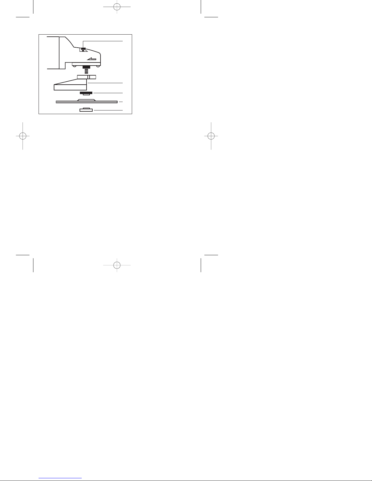
1 Spindelarretierung
2 Schutzhaube
3 Spannflansch *
4 Schleifscheibe
5 Flanschmutter *
1 Spindle catch
2 Guard
3 Clamping flange *
4 Grinding wheel
5 Flange nut *
1 Enclavamiento de husillo
2 Cubierta protectora
3 Brida de sujección *
4 Muela de afilar
5 Tuerca de brida *
1
2
3
4
5
* Anordnung der Flansche siehe Seite 6
* Flange arrangement see page 9
*Posición de las bridas vésse página12
* Para a disposição dos flanges veja pàg. 15
* Per la disposizione della flangia vedi pag. 18
* Flänsens ordning se sidan 21
* Laipan sijoitus, katso sivu 24
* Placering af flangen se side 27
* Rozmieszczenie kołnierzy - patrz strona numer 30
* A karima felépítéséhez lásd az 33-ik oldalt
* Raspored prirubnica vidi stranicu 36
* Izvedba prirobnice - glej stran 39
1 Fixação do rebolo
2 Capa de protecção
3 Flange de aperto *
4 Disco
5 Tuerca de brida *
1 Arresto del mandrino
2 Carter di protezione
3 Flangia fissaggio *
4 Disco
5 Dado fissaggio *
1 Spindelfastlåsning
2 Skyddskåpa
3 Spännfläns *
4 Slipskiva
5 Flänsmutter *
1 Karanlukitus
2 Suojus
3 Kiinnityslaippa *
4 Hiomalaikka
5 Laippamutteri *
1 Spindelfastlåsning
2 Sikkerhedsskærm
3 Spændeflange *
4 Slibesklve
5 Fangemøtrik *
1. Blokada wrzeciona
2. Kołpak ochronny
3. Kołnierz mocujący*
4. Ściernica tarczowa
5. Nakrętka kołnierzowa*
1 Tengeljrögzítő
2 Védőburok
3 Fogatkarima *
4 Csiszolókorong
5 Karimás anya *
1. Naprava za aretiranje vretena
2. Štitnik
3. Stezna prirubnica *
4. Brusna ploča
5. Prirubnička matica *
1 aretirna zapora vretena
2 zaščitni pokrov
3 napenjalna prirobnica *
4 brusilna plošča
5 matica prirobnice *
Anleitung E-WS 125-950 SPK 7 13.08.2004 7:45 Uhr Seite 2
Page 3
3
1
2
D Augenschutz tragen!
Wear goggles!
E Use óculos de protecção!
P ¡Póngase gafas protectoras!
I Portare occhiali protettivi!
S Använd ögonskydd!
Käytä suojalaseja!
Bær øjenværn
Nosić okulary ochronne!
H Hordjon szemvédőt!
Nosite zaštitne naočale.
Na očeh nosite zaščito za oči !
D Gebrauchsanweisung beachten!
Follow the operating instructions
E Tenga en cuenta las instrucciones de uso
P Respeitar as instruções de serviço
I Osservate le istruzioni per l’uso
S Beakta bruksanvisningen
Noudata käyttöohjetta
Bemærk anvisningerne i betjeningsvejledningen
Przestregać instrukcji obsługi
H Vegye figyelembe a használati utasítást.
Uvažite naputak za uporabu
Upoštevajte navodila za uporabo
Anleitung E-WS 125-950 SPK 7 13.08.2004 7:45 Uhr Seite 3
Page 4
4
Sicherheitshinweise
Die entsprechenden Sicherheitshinweise entnehmen
Sie bitte den beiliegenden Heftchen.
Betriebsanleitung für Winkelschleifer
VERWENDUNG
Der Winkelschleifer ist zum Trenn- und Schruppschleifen von Metallen und Gestein unter Verwendung der entsprechenden Trenn- oder Schruppscheibe bestimmt.
SPANNUNG
Prüfen Sie vor der Inbetriebnahme, ob die auf dem
Typenschild angegebene Spannung mit der
Netzspannung übereinstimmt. Die Netzspannung
sollte in keinem Fall um mehr als 10 % von der
angegebenen Nennspannung abweichen.
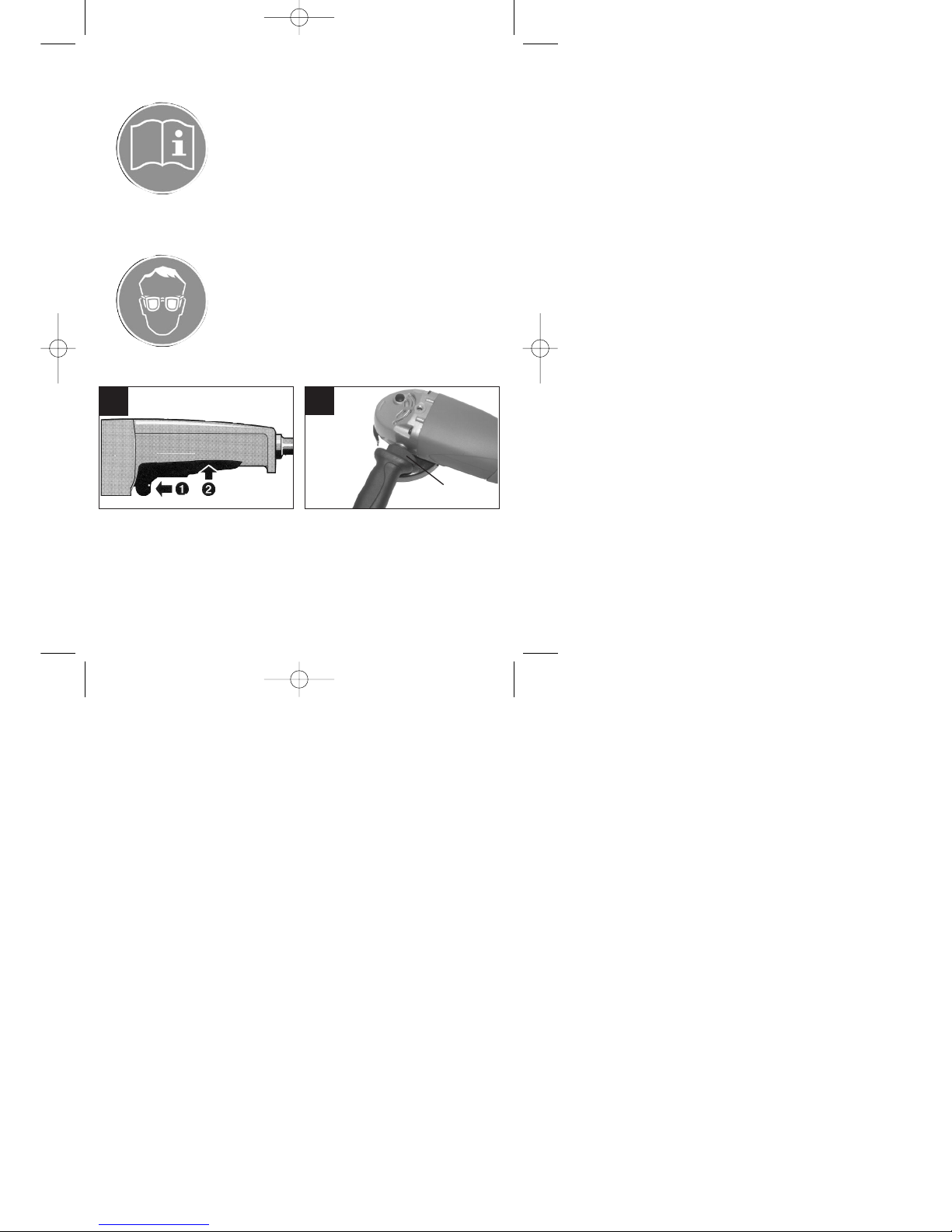
SCHALTER (Bild 1)
Der Winkelschleifer ist mit einem Sicherheitsschalter
zur Unfallverhütung ausgestattet.
Zum Einschalten die Sperrtaste (1) nach vorne
schieben und die Schaltertaste (2) drücken. Zum
Ausschalten die Schaltertaste (2) loslassen.
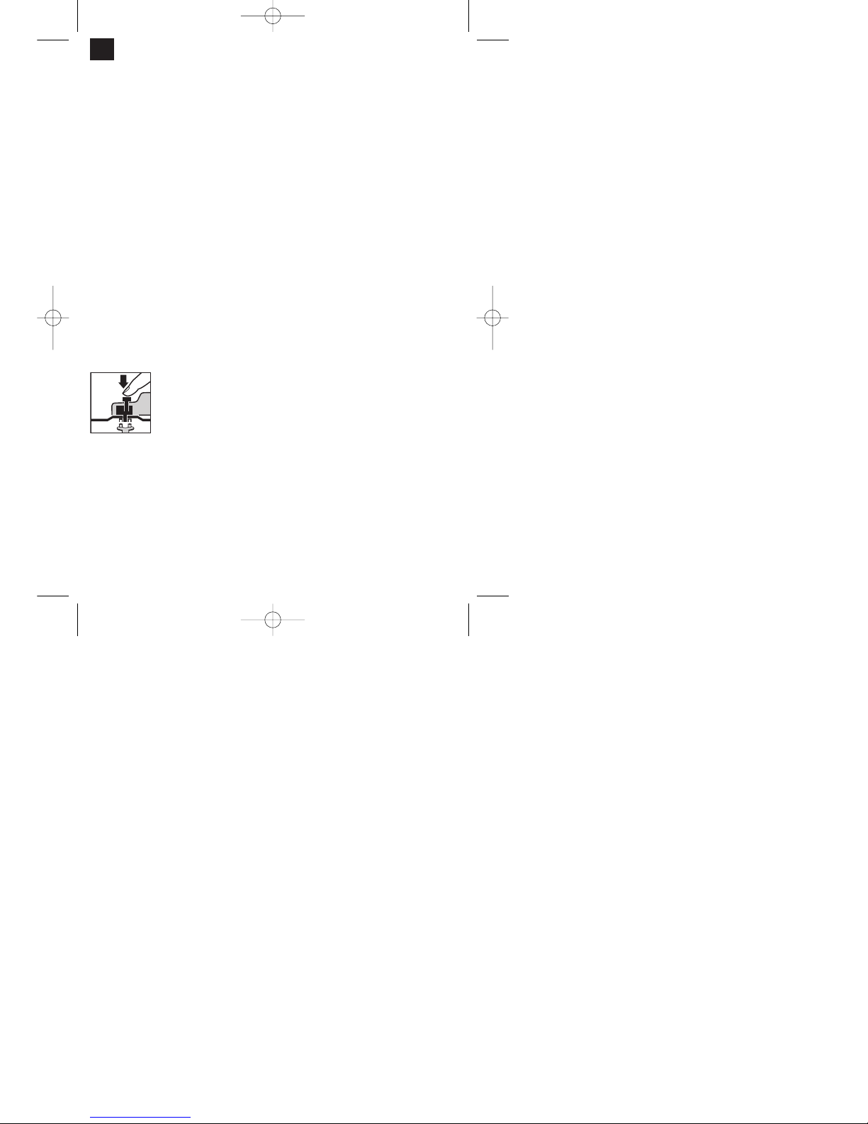
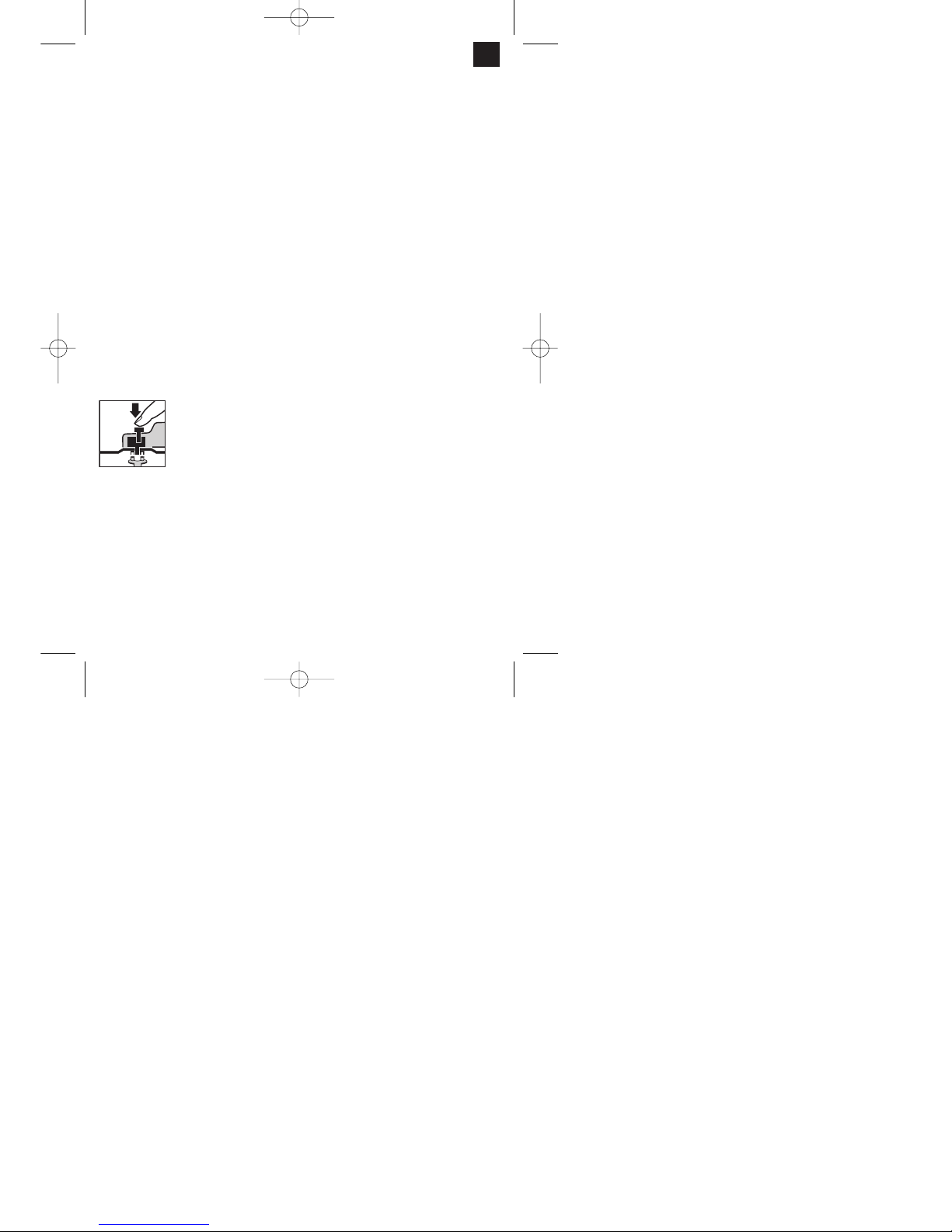
AUSTAUSCH DER SCHLEIFSCHEIBEN
Netzstecker ziehen!
Einfacher Scheibenwechsel durch
Spindelarretierung.
Spindelarretierung drücken und
Schleifscheibe einrasten lassen.
Die Flanschmutter mit dem
Stirnlochschlüssel öffnen.
Schleif- oder Trennscheibe
wechseln und Flanschmutter mit
dem Stirnlochschlüssel
festziehen.
Achtung:
Spindelarretierung nur bei stillstehendem Motor
und Schleifspindel drücken!
Die Spindelarretierung muß während des
Scheibenwechsels gedrückt bleiben!
Bei Schleif- oder Trennscheiben bis ca. 3 mm Dicke,
die Flanschmutter mit der Planseite zur Schleif- oder
Trennscheibe aufschrauben.
PROBELAUF NEUER SCHLEIFSCHEIBEN
Den Winkelschleifer mit montierter Schleif- oder
Trennscheibe mindestens 1 Minute im Leerlauf
laufen lassen. Vibrierende Scheiben sofort
austauschen.
MOTOR
Der Motor muß während der Arbeit gut belüftet
werden, daher müssen die Lüftungsöffnungen immer
sauber gehalten werden.
ZUSATZHANDGRIFF (Bild 2)
Der Winkelschleifer ist mit einem speziellen Handgriff
ausgestattet, welcher der jeweiligen Arbeitsposition
angepasst werden kann. Zum Fixieren des Zuzsatzhandgriffes, die Kontermutter (1) ganz auf den Zusatzhandgriff aufschrauben. anschliessend den Zusatzhandgriff ebenfalls ganz auf den Winkelschleifer
aufschrauben. Nun den Handgriff auf die gewünschte Position einstellen und mit der Kontermutter (1)
sichern.
Achtung! Das Gewinde des Zusatzhandgriffes muss
soweit wie möglich in den Winkelschleifer geschraubt
werden.
SCHLEIFSCHEIBEN
Die Schleif- oder Trennscheibe darf nie größer als
der vorgeschriebene Durchmesser sein.
Kontrollieren Sie vor dem Einsatz der Schleif- oder
Trennscheibe deren angegebene Drehzahl. Die
Drehzahl der Schleif- oder Trennscheibe muß höher
sein als die Leerlaufdrehzahl des Winkelschleifers.
Verwenden Sie nur Schleif- und Trennscheiben die
für eine minimale Drehzahl von 11.000 min
-1
und für
eine Umfangsgeschwindigkeit vom 80 m/sec.
zugelassen sind.
ARBEITSHINWEISE
Schruppschleifen
Der beste Erfolg beim Schruppschleifen wird
erreicht, wenn Sie die Schleifscheibe in einem
Winkel von 30° bis 40° zur Schleifebene ansetzen
und gleichmäßig über das Werkstück hin- und herbewegen.
Trennschleifen
Bei Trennarbeiten den Winkelschleifer in der
Schneidebene nicht verkanten. Die Trennscheibe
muß eine saubere Schnittkante aufweisen.
Zum Trennen von harten Gestein verwenden Sie am
besten eine Diamant-Trennscheibe.
Asbesthaltige Materialien dürfen nicht bearbeitet
werden!
D
STOP
Anleitung E-WS 125-950 SPK 7 13.08.2004 7:45 Uhr Seite 4
Page 5

5
Verwenden Sie niemals Trennscheiben zum
Schruppschleifen.
TECHNISCHE DATEN
Nennspannung: 230 V ~ 50 Hz
Leistungsaufnahme: 950 W
Leerlaufdrehzahl: 11.000 min
-1
max. Scheiben Ø: 125 mm
Gewinde der Antriebsspindel: M 14
Schalldruckpegel LPA: 89,6 dB (A)
Schalleistungspegel LWA: 102,6 dB (A)
Vibration a
–
w
2,8 m/s
2
Schutzisoliert II /
Gewicht 2,5 Kg
Ersatzteilbestellung
Bei der Ersatzteilbestellung sollten folgende Angaben gemacht werden;
Typ des Gerätes
Artikelnummer des Gerätes
Ident-Nummer des Gerätes
Ersatzteilnummer des erforderlichen Ersatzteils
Ersatzteil Ersatzteil-Nr.
Ersatzkohlen 44.720.10.01.001
Schalter 44.720.10.01.002
D
Anleitung E-WS 125-950 SPK 7 13.08.2004 7:45 Uhr Seite 5
Page 6

6
D
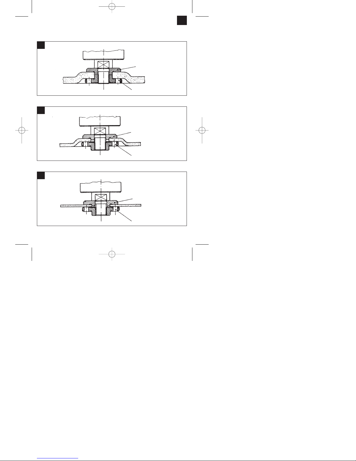
Anordnung der Flansche bei Verwendung von
Schleifscheiben und Trennscheiben
1
Spannflansch
Flanschmutter
Anordnung der Flansche bei Verwendung einer gekröpften oder geraden Schleifscheibe
2
Spannflansch
Flanschmutter
Anordnung der Flansche bei Verwendung einer gekröpften Trennscheibe
3
Spannflansch
Flanschmutter
Anordnung der Flansche bei Verwendung einer geraden Trennscheibe
Anleitung E-WS 125-950 SPK 7 13.08.2004 7:45 Uhr Seite 6
Page 7
7
Safety regulations
The corresponding safety information can be
found in the enclosed booklet.
Operating instructions for
right-angle grinders
The machine is light, handy, totally insulated and
designed in compliance with the international
specifications CEE 20. Provided it is serviced as
described in these instructions, the machine will
serve you for a long time.
VOLTAGE
Before you use the machine for the first time, check
that the voltage marked on the rating plate is the
same as your mains voltage. Under no
circumstances is the mains voltage to differ from the
rated voltage by more than 10%.
SWITCH (Fig. 1)
The angle grinder comes with a safety switch which
is designed to prevent accidents. To switch on, push
the locking button (1) forward and press the switch
button (2). To switch off, let go of the switch button
(2).
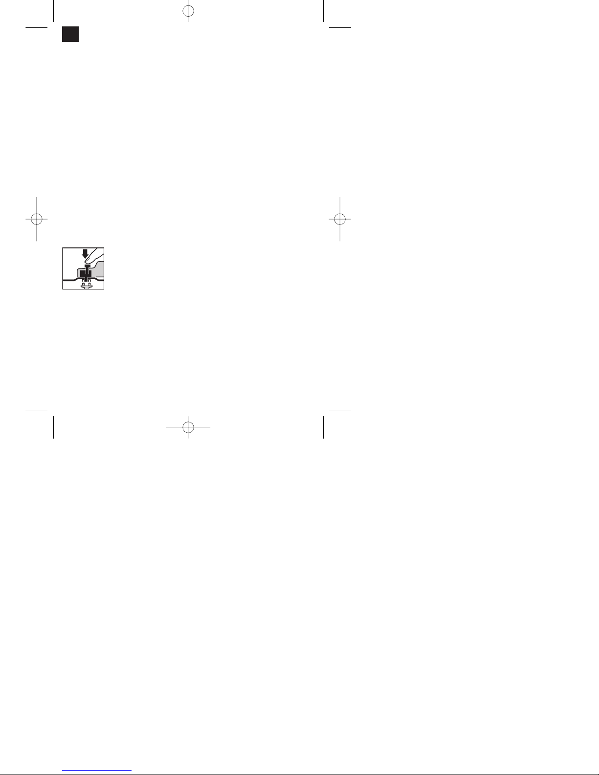
REPLACING THE GRINDING WHEEL
Pull out the power plug.
Simple wheel change by spindle
lock: Press the spindle lock and
allow the grinding wheel to latch
in place.Open the flange nut with
the face spanner.
Change the grinding or cutting
wheel and tighten the flange nut
with the face spanner.
Important! Only ever press the spindle lock
when the motor and grinding spindle are at a
standstill! You must keep the spindle lock
pressed while you change the wheel!
For grinding or cutting wheels up to approx. 3 mm
thick, screw on the flange nut with the flat side facing
the grinding or cutting wheel.
TEST RUN FOR NEW GRINDING WHEELS
Allow the right-angle grinder to run in idle for at least
1 minute with the grinding or cutting wheel fitted in
place. Vibrating wheels are to be replaced
immediately.
MOTOR
It is vital for the motor to be well ventilated during
operation. Be sure, therefore, to keep the ventilation
holes clean at all times.
ADDITIONAL HANDLE (FIG. 2)
The angle grinder comes with a special additional
handle that can be adapted to the working position in
question.
To fix the additional handle in position, turn the lock
nut (1) all the way onto the additional handle. Then
screw the additional handle fully onto the angle
grinder. Now adjust the handle to the position
required and fix it in place with the lock nut (1).
Important! The thread of the additional handle has to
be screwed as far as possible into the angle grinder.
CARBON BRUSHES
Carbon brushes that are burned, broken or shorter
than 5 mm are to be replaced by original
replacement brushes. Always replace the carbon
brushes in pairs.
GRINDING WHEELS
Never use a grinding or cutting wheel bigger than the
specified diameter.
Before using a grinding or cutting wheel, check its
rated speed. The wheel´s rated speed must be
higher than the idle speed of the right-angle grinder.
Use only grinding and cutting wheels that are
approved for a minimum speed of 11,000 rpm and a
peripheral speed of 80 m/sec.
OPERATING MODES
Rough grinding:
For the best rough grinding results, hold the grinding
wheel at an angle of between 30° and 40° to the
workpiece surface and guide back and forth over the
workpiece in steady movements.
Cutting:
When you use the right-angle grinder for cutting
purposes, avoid tilting it in the cutting plane. The
cutting wheel must have a clean cutting edge.
A diamond cutting wheel is best used to cut hard
stone.
It is prohibited to use the machine on asbestos
materials!
Never use a cutting wheel for rough
grinding.
GB
STOP
Anleitung E-WS 125-950 SPK 7 13.08.2004 7:45 Uhr Seite 7
Page 8

8
TECHNICAL DATA
Nominal voltage: 230 V ~ 50 Hz
Power consumption: 950 W
Idle speed: 11.000 rpm
Max. wheel diameter: 125 mm
Drive spindle thread: M 14
Sound pressure level LPA: 89,6 dB(A)
Sound power level LWA: 102,6 dB(A)
Vibration a
–
w
2,8 m/s
2
Weight 2,5 kg
Totally insulated II /
Ordering replacement parts
Please quote the following data when ordering
replacement parts:
Type of machine
Article number of the machine
Identification number of the machine
Replacement part number of the part required
Replacement part Replacement part number
Carbon brush 44.720.10.01.001
Switch 44.720.10.01.002
GB
Anleitung E-WS 125-950 SPK 7 13.08.2004 7:45 Uhr Seite 8
Page 9
9
GB
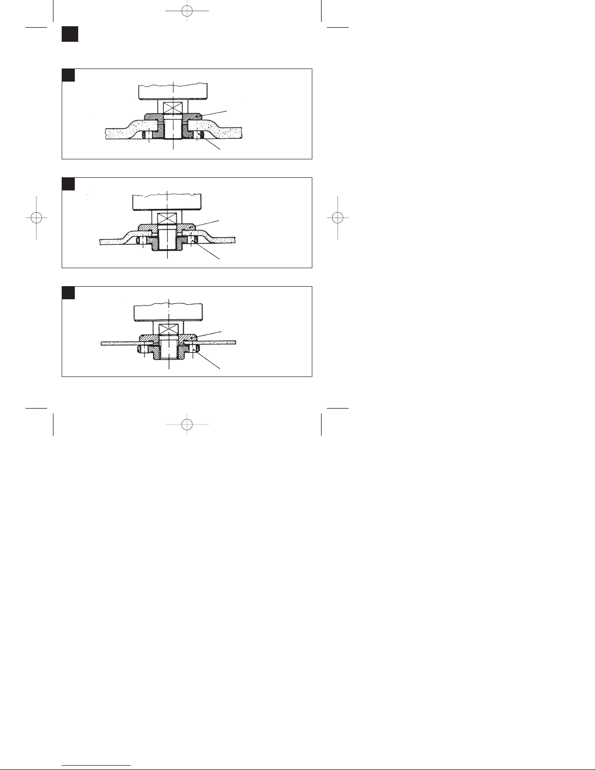
Flange arrangements when using grinding
wheels and cutting wheels
1
Clamping flange
Flange nut
Flange arrangement when using a depressed-centre or straight grinding wheel
2
Clamping flange
Flange nut
Flange arrangement when using a depressed-centre cutting wheel
3
Clamping flange
Flange nut
Flange arrangement when using a straight cutting wheel
Anleitung E-WS 125-950 SPK 7 13.08.2004 7:45 Uhr Seite 9
Page 10
10
Advertencias de seguridad:
Encontrará las instrucciones de seguridad
correspondientes en el prospecto adjunto.
Instrucciones de servicio de la lijadora
angular
El aparato es ligero y fácil de manejar, está provisto
de un aislamiento protector y ha sido concebido
según las disposiciones internacionales CEE 20. El
aparato tiene una larga duración de vida si se
observan las instrucciones de mantenimiento
siguientes.
TENSION
Antes de la puesta en marcha compruebe que la
tensión indicada en la placa de características
concuerda con la tensión en la red. Dicha tensión no
deberá diferir en ningún momento más del 10% de la
tensión indicada.
INTERRUPTOR (FIG. 1)
La lijadora angular está equipada con un interruptor
de seguridad para prevenir accidentes. Para
conectar la tecla de bloqueo (1), desplazarla hacia
delante y presionar la tecla del interruptor (2). Para
desconectar, soltar la tecla del interruptor (2).
COMO CAMBIAR EL PAPEL DE LIJA
Primeramente desenchufar el aparato.
A continuación presione el
bloqueo del husillo para enclavar
el disco.
Abra la tuerca bridada con la
llave de espigas frontales.
Cambie el disco de muela o de
corte y apriete de nuevo la tuerca
bridada con la llave.
¡Atención: Presione únicamente el bloqueo del
husillo si el motor y el husillo se hallan parados!
¡El bloqueo del husillo debe permanecer
presionado durante el cambio del disco!
En caso de discos de lijado o de corte de hasta
3 mm es preciso desatornillar la tuerca bridada con
el lado plano hacia el disco.
FUNCIONAMIENTO DE PRUEBA DE LOS
NUEVOS DISCOS DE LIJADO.
Ponga la lijadora en marcha al menos durante un
minuto con el nuevo disco de lijado o de corte.
Discos que se pongan a vibrar deberán ser
sustituidos inmediatamente.
MOTOR
El motor deberá estar bien ventilado durante su
funcionamiento, las ranuras de ventilación deberán
mantenerse por tanto siempre limpias.
EMPUÑADURA ADICIONAL (fig. 2)
La lijadora angular está equipada de una
empuñadura adicional que se puede adaptar a la
posición de trabajo correspondiente. Para fijar la
empuñadura adicional, destornillar completamente la
tuerca de bloqueo (1) en dicha empuñadura.
Seguidamente, destornillar igualmente la
empuñadura adicional en la lijadora angular.
Finalmente, colocar la empuñadura en la posición
deseada y apretarla con la tuerca de seguridad (1).
¡Atención! Es preciso atornillar al máximo posible la
rosca de la empuñadura adicional en la lijadora
angular.
DISCOS DE LIJADO
Los discos de lijado o de corte no deberán superar el
diámetro previsto. Antes de usar los discos
compruebe el número de revoluciones que se indica
en éllos. Dicho número debe ser mayor al de las
revoluciones en vacio indicadas para la lijadora
angular.
Emplee siempre discos de lijado o de corte que
hayan sido homologados para una velocidad
máxima de 11.000 min
-1
y para una velocidad
periférica de 80 m/seg.
INSTRUCCIONES DE USO
Lijado grueso o de desbaste
Los mejores resultados en la lijadura de desbaste se
obtienen manteniendo el disco a un ángulo de 30º a
40º respecto a la superficie de lijado y desplazando
la lijadora con movimientos regulares sobre la pieza
a trabajar.
Corte
No incline la lijadora respecto al plano de corte. El
disco deberá presentar un reborde de corte limpio.
Para cortar piedra dura se empleará
preferentemente un disco de corte adiamantado.
¡No trabaje con materiales que contengan
amianto
No use nunca discos de corte para
desbastar.
E
STOP
Anleitung E-WS 125-950 SPK 7 13.08.2004 7:45 Uhr Seite 10
Page 11

11
Características técnicas:
Tensión de la red: 230 V ~ 50 Hz
Potencia absorbida 950 Watios
Revoluciones en vacio: 11.000 min
-1
Ø max. del disco 125 mm
Rosca del husillo motriz: M 14
Nivel de presión acústica LPA: 89,6 dB(A)
Nivel de potencia acústica LWA: 102,6 dB(A)
Vibración
a
–
w
2,8 m/s
2
Peso 2,5 kg
Aislamiento protector II /
Pedido de piezas de recambio
A la hora de pasar pedido de piezas de recambio, es
preciso que indique los siguientes datos:
Tipo de aparato
Número de artículo del aparato
Número de identificación del aparato
Número de la pieza de recambio requerida
Pieza de recambio Núm. pieza de recambio
Interruptor 44.720.10.01.002
Carbón recambio 44.720.10.01.001
E
Anleitung E-WS 125-950 SPK 7 13.08.2004 7:45 Uhr Seite 11
Page 12
12
E
Disposición de las bridas en el uso de
discos de lijado o de corte
1
Brida de tensado
Tuerca bridada
Disposición de las bridas si se emplea un disco de lijado acodado o recto
2
Brida de tensado
Tuerca bridada
Disposición de las bridas si se emplea un disco de corte acodado.
3
Brida de tensado
Tuerca bridada
Disposición de las bridas si se emplea un disco de corte recto.
Anleitung E-WS 125-950 SPK 7 13.08.2004 7:45 Uhr Seite 12
Page 13

13
Instruções de segurança:
As instruções de segurança correspondentes
encontram-se na brochura fornecida.
Instruções de serviço para a
rectificadora angular
A máquina é leve e de fácil manejo, tem um
isolamento de protecção e corresponde às
disposições internacionais CEE 20. A máquina tem
uma longa vida, se for conservada conforme as
instruções seguintes.
TENSÃO
Antes de usar a máquina pela primeira vez, verifique
se a tensão indicada na placa de características é
igual à tensão da rede. A tensão indicada não deve
diferir, em nenhum caso, mais de 10% da tensão da
rede.
INTERRUPTOR (figura 1)
A rebarbadora está equipada com um interruptor de
segurança, destinado a prevenir acidentes. Para
ligar, empurrar a tecla de travamento (1) para a
frente e premir o interruptor para ligar/desligar (2).
Para desligar, solte o interruptor para ligar/desligar
(2).
TROCA DOS REBOLOS
Tire a ficha da tomada.
A troca dos rebolos é fácil devido
ao bloqueio do fuso. Aperte o
bloqueio do fuso e deixe engatar
o rebolo.
Abra a porca do flange com a
chave de furos.
Troque o rebolo e aperte a porca
do flange com a chave de furos.
ATENÇÃO: Aperte o bloqueio do fuso somente
quando o motor e o fuso estiverem parados!
Durante a troca do rebolo, o bloqueio do fuso
deve ficar apertado!
No caso de rebolos de até aprox. 3 mm de
espessura, aperte a porca do flange com o lado
plano em direcção ao rebolo.
MARCHA DE ENSAIO DE REBOLOS NOVOS
Deixe funcionar a rectificadora angular com o rebolo
montado pelo menos durante um minuto em vazio.
Substitua imediatamente os rebolos que vibrem.
MOTOR
O motor sempre deve ter boa ventilação durante o
trabalho. Por isso, as aberturas de ventilação
sempre devem estar limpas.
PUNHO ADICIONAL (figura 2)
A rebarbadora possui um punho especial, que pode
ser adaptado à posição de trabalho. Para fixar o
punho adicional, enrosque completamente a
contraporca (1) no punho adicional. A seguir,
enrosque também o punho adicional na rebarbadora.
Agora, coloque o punho na posição desejada e fixeo por meio da contraporca (1).
Atenção! A rosca do punho adicional tem de ser
enroscada o mais possível na rebarbadora.
REBOLOS
O rebolo nunca deve ser maior que o diâmetro
prescrito.
Antes de usar o rebolo, controle o número de
rotações indicado. O número de rotações do rebolo
deve ser superior ao número de rotações em vazio
da rectificadora angular.
Use somente rebolos admitidos para uma velocidade
de rotação máxima de 11.000 r.p.m.
e uma velocidade periférica de 80 m/seg.
OBSERVAÇÕES SOBRE O TRABALHO
Rectificação de desbaste
Na rectificação de desbaste, obtém-se o melhor
resultado quando se aplica o rebolo num ângulo de
30 ° a 40 ° em relação à superfície e se move o
mesmo regularmente sobre a
peça, de um lado ao outro.
Corte com o rebolo
Ao cortar com o rebolo, tome cuidado para que a
rectificadora angular não emperre na superfície de
corte. O rebolo deve ter uma aresta de corte limpa.
Para cortar pedras duras, use de preferência um
rebolo com diamantes.
Não é permitido trabalhar materiais que contêm
amianto!
Nunca use rebolos separadores para a
rectificação de desbaste.
P
STOP
Anleitung E-WS 125-950 SPK 7 13.08.2004 7:45 Uhr Seite 13
Page 14

14
DADOS TÉCNICOS
Tensão nominal: 230 V c.a. 50 Hz
Potência: 950 W
Número de rotações em vazio: 11.000 r.p.m.
ø máx. do rebolo: 125 mm
Rosca do fuso de accionamento: M 14
Nível da pressão acústica: 89,6 dB (A)
Nível da potência acústica: 102,6 dB (A)
Vibração a
–
w
2,8 m/s
2
Peso 2,5 kg
Com isolamento protecção II /
Encomenda de peças sobressalentes
Para encomendar peças sobressalentes, devem ser
efectuadas as seguintes indicações:
Modelo do aparelho
Número de referência do aparelho
N.º de identificação do aparelho
Número de peça sobressalente necessária
Peça sobressalente N.º da peça sobressalente
Interruptor 44.720.10.01.002
Escovas sobressalentes 44.720.10.01.001
P
Anleitung E-WS 125-950 SPK 7 13.08.2004 7:45 Uhr Seite 14
Page 15

15
P
Disposição dos flanges ao usar-se rebolos
e rebolos separadores
1
Flange de aperto
Porca do flange
Disposição dos flanges ao usar-se um rebolo separador rebaixado ou recto
2
Flange de aperto
Porca do flange
Disposição dos flanges ao usar-se um rebolo separador rebaixado
3
Flange de aperto
Porca do flange
Disposição dos flanges ao usar-se um rebolo separador recto
Anleitung E-WS 125-950 SPK 7 13.08.2004 7:45 Uhr Seite 15
Page 16

16
Avvertenze sulla sicurezza
Le relative avvertenze di sicurezza si trovano
nell’opuscolo allegato.
Istruzioni per il funzionamento della
smerigliatrice angolare
La macchina è leggera, facile da maneggiare,
provvista di isolamento protettivo e concepita
secondo le disposizioni internazionali CEE 20. Si
assicura una lunga durata se la manutenzione viene
eseguita secondo queste avvertenze.
TENSIONE
Prima della messa in esercizio controllare che la
tensione di rete corrisponda a quella indicata sulla
targhetta. La tensione di rete non deve
assolutamente differire di più del 10% dalla tensione
nominale indicata.
INTERRUTTORE
La smerigliatrice angolare è dotata di un interruttore
di sicurezza per la prevenzione degli infortuni. Per
l’inserimento, spingete in avanti il tasto di bloccaggio
(1) e premete l’interruttore (2). Per disinserire,
lasciate andare l’interruttore (2).
SOSTITUZIONE DELLA MOLA
Togliere la spina dalla presa di alimentazione.
Facile sostituzione della mola
grazie all´arresto del mandrino.
Premere l´arresto del mandrino e
far scattare in posizione la mola.
Aprire il dado flangiato con la
chiave a pioli.
Sostituire la mola di smerigliatura
o di troncatura e serrare il dado
flangiato con la chiave a pioli.
Attenzione:
Premere l´arresto del mandrino solo se il
motore ed il mandrino di smerigliatura sono
fermi! Durante la sostituzione della mola l´arresto
del mandrino deve rimanere premuto!
Nel caso di mole di smerigliatura o di troncatura fino
a 3 mm di spessore, avvitare il dado flangiato con il
lato piatto verso la mola.
FUNZIONAMENTO DI PROVA DI UNA MOLA
NUOVA
Far funzionare a vuoto per almeno 1 minuto la
smeriglitrice angolare con la mola di smerigliatura o
di troncatura montata. Se la mola vibra, sostituirla
subito.
MOTORE
Il motore deve essere ben ventilato durante il
funzionamento, per questo motivo le aperture di
areazione devono sempre essere tenute pulite.
IMPUGNATURA SUPPLEMENTARE
La smerigliatrice angolare è dotata di una speciale
impugnatura supplementare che può venire adattata
a qualsiasi posizione di lavoro.
Per fissare l’impugnatura supplementare, avvitate
completamente il controdado (1) sull’impugnatura
stessa. Poi avvitate completamente anche
l’impugnatura addizionale sulla smerigliatrice
angolare. Ora impostate l’impugnatura nella
posizione desiderata e fissatela con il controdado
(1).
Attenzione! Il filetto dell’impugnatura addizionale
deve essere avvitato il più possibile alla
smerigliatrice angolare.
SPAZZOLE DI CARBONE
Se le spazzole di carbone sono bruciate, rotte o più
piccole di 5 mm, devono essere sostituite con
spazzole di ricambio originali. Sostituire le spazzole
sempre a coppie.
MOLE DI SMERIGLIATURA
La mola di smerigliatura o di troncatura non deve
superare il diametro prescritto. Prima di usare la
mola controllarne il numero giri indicato. Il numero di
giri della mola di smerigliatura o di troncatura deve
essere maggiore del numero di giri a vuoto della
smerigliatrice angolare.
Usare solamente mole di smerigliatura o di
troncatura che siano omologate per un numero
massimo di giri di 11.000 min
-1
e per una velocità
periferica di 80 m/sec.
AVVERTIMENTI PER L´USO
Smerigliatura di sgrossatura
I risultati migliori nella sgrossatura si ottengono
ponendo la mola in un angolo che va dai 30° ai 40°
rispetto alla supericie da smerigliare e spostandola
sul pezzo da lavorare con movimenti regolari da
destra a sinistra e viceversa.
Smerigliatura di troncatura
Per la troncatura non inclinare la smerigliatrice sul
piano di taglio. La mola di troncatura deve
presentare uno spigolo di taglio netto.
Per troncare pietre dure si consiglia di unsare una
mola diamantata.
I
STOP
Anleitung E-WS 125-950 SPK 7 13.08.2004 7:45 Uhr Seite 16
Page 17

17
Non devono venir lavorati materiali contenenti
amianto!
Per la sgrossatura non usare mai mole per
troncare.
DATI TECNICI
Tensione nominale: 230 V ~ 50 Hz
potenza assorbita: 950 W
numero giri a vuoto: 11.000 min
-1
ø max. mola: 125 mm
filetto del mandrino motore: M 14
livello di pressione acustica LPA: 89,6 dB (A)
livello di potenza sonora LWA: 102,6 dB (A)
Vibrazione a
–
w
2,8 m/s
2
Peso 2,5 kg
Con isolamento protettivo II /
Commissione dei pezzi di ricambio
Volendo commissionare dei pezzi di ricambio, si
dovrebbe dichiarare quanto segue:
modello dell’apparecchio
numero dell’articolo dell’apparecchio
numero d’ident. dell’apparecchio
numero del pezzo di ricambio del ricambio ssitat
Pezzo di ricambio N. pezzo di
ricambio
Spazzole di carbone di ricambio 44.720.10.01.001
Interruttore 44.720.10.01.002
I
Anleitung E-WS 125-950 SPK 7 13.08.2004 7:45 Uhr Seite 17
Page 18

18
I
Posizione della flangia se si impiegano
mole per smerigliatura e troncatura
1
flangia di serraggio
dado flangiato
Posizione della flangia se si impiega una mola per smerigliatura piegata a gomito o diritta
2
flangia di serraggio
dado flangiato
Posizione della flangia se si impiega una mola per troncatura piegata a gomito
3
flangia di serraggio
dado flangiato
Posizione della flangia se si impiega una mola per troncatura diritta
Anleitung E-WS 125-950 SPK 7 13.08.2004 7:45 Uhr Seite 18
Page 19

19
Säkerhetsanvisningar:
Gällande säkerhetsanvisningar finns i det
bifogade häftet.
Bruksanvisning til vinkelslipmaskin
Maskinen är lätt och behändig, den är
skyddsisolerad och uppbyggd enligt de
internationella bestämmelserna CEE 20. Maskinen
har lång hållbarhet om den sköts enligt
nedanstående anvisningar.
SPÄNNING
Kontrollera före driftstart om den spänning som
anges på typplåten överensstämmer med
nätspänningen. Nätspänningen får under inga
omständigheter avvika mer än 10% från den angivna
nominella spänningen.
STRÖMBRYTARE
För att undvika olyckor är vinkelslipen utrustad med
en säkerhetsbrytare. För att koppla in, tryck
spärrknappen (1) framåt och tryck ned brytaren (2).
Släpp brytaren (2) för att koppla ifrån.
BYTE AV SLIPSKIVOR
Dra ut nätkontakten!
Enkelt skivbyte genom
spindelfstlåsning. Tryck på
spindelfastlåsningen så att
slipskivan hålls kvar. Öppna
flänsmuttern med en
stjärnhålnyckel . Byt slip- eller
avskiljningsskiva och dra åt
flänsmuttern med
stjärnhålnyckeln.
Observera:
Spindelfastlåsningen får bara tryckas ned då
motorn och slipspindeln är avstängda.
Spindelfastlåsningen ska vara nedtryckt under
skivbytet!
När det gäller slip- eller avskiljningsskivor som är upp
till ca 3 mm tjocka ska flänsmuttern skruvas på med
plansidan åt slip- eller avskiljningsskivan.
PROVKÖRNING AV NYA SLIPSKIVOR
Vinkelslipmaskinen med den monterade slip- eller
avskiljningsskivan ska gå på tomgång i minst 1
minut. Vibrerande skivor ska bytas ut omedelbart.
MOTOR
Motorn måste vara väl ventilerad under arbetet. Av
den anledningen ska ventilationsöppningarna alltid
vara väl rengjorda.
STÖDHANDTAG
Vinkelslipen är utrustad med ett speciellt
stödhandtag som kan anpassas till avsett arbetsläge.
För att fixera stödhandtaget, skruva fast
kontramuttern (1) komplett på stödhandtaget. Skruva
därefter fast stödhandtaget helt på vinkelslipen. Ställ
in handtaget i avsett läge och fixera med
kontramuttern (1).
Obs! Stödhandtagets gängor måste skruvas in i
vinkelslipen så långt som möjligt.
KOLBORSTAR
Om kolborstarna är förbrända, brutna eller kortare än
5 mm ska de bytas ut mot original-kolborstar. Byt
alltid ut kolborstarna parvis.
SLIPSKIVOR
Slip- eller avskiljningsskivan får aldrig vara större än
den föreskrevna diametern. Kontrollera före skivorna
tas i bruk vilka varvtal som angetts. Slip- eller
avkiljningsskivans varvtal måste vara högre än
varvtalet då vinkelslipmaskinen går på tomgång.
Använd endast slip- och avskiljningsskivor som är
tillåtna för ett maximalt varvtal på 11.000 min och för
en omfångshastighet på 80 m/sek.
ARBETSANVISNINGAR
Grovslipning
Bäst resultat vid grovslipning får ni om ni placerar
slipskivan i en vinkel på 30 till 40 grader till slipytan
och för den jämnt fram och tilbaka över
arbetsdetaljer.
Avskiljningsslipning
Vid avskiljningsarbeten får vinkelslipmaskinen inte
förskjutas i snittytan. Avskiljningsskivan måste göra
en ren snittkant. För att avkilja hård sten är det bäst
att använda en diamantavskiljningsskiva.
Material som innehåller asbest får ej bearbetas!
Använd aldrig avskiljningsskivor till
grovslipning.
S
STOP
Anleitung E-WS 125-950 SPK 7 13.08.2004 7:45 Uhr Seite 19
Page 20

20
Tekniska data
Nominell spänning: 230V ~ 50 Hz
Effektupptagning: 950 W
Tomgångsvarvtal: 11 000 min
-1
max. skivor: 125 mm
Drivspindelns gänga: M 14
Ljudtrycksnivå: 89,6 dB (A)
Ljudeffektnivå. 102,6 dB (A)
Vibration a
–
w
2,8 m/s
2
Vikt 2,5 kg
Dubbel isolering II /
Reservdelsbeställning
Lämna följande uppgifter vid beställning av
reservdelar:
Maskintyp
Maskinens artikel-nr.
Maskinens ident-nr.
Reservdelsnummer för erforderlig reservdel
Reservdel Reservdelsnummer
Reservkol 44.720.10.01.001
Brytare 44.720.10.01.002
S
Anleitung E-WS 125-950 SPK 7 13.08.2004 7:45 Uhr Seite 20
Page 21

21
S
Flänsernas ordning vid användning
av slipskivor och avskiljningsskivor
1
Spännfläns
Flänsmutter
Arrangemang av flänsen vid användning av en krökt eller rak slipskiva
2
Spännfläns
Flänsmutter
Arrangemang av flänsen vid användning av en krökt avskiljnngsskivor
3
Spännfläns
Flänsmutter
Arrangemang av flänsen vid användning av en rak avskiljnngsskiva
Anleitung E-WS 125-950 SPK 7 13.08.2004 7:45 Uhr Seite 21
Page 22

22
Turvallisuusohjeet:
Laitetta koskevat turvallisuusmääräykset löydät
oheistetusta vihkosesta.
Kulmahiomakoneen käyttöohjeet
Kulmahiomakone on kevyt ja kätevä. Se on
suojaeristetty ja valmistettu kansainvälisten
CEE 20 -määräysten mukaisesti. Se käyttöikä on
pitkä, jos sitä huolletaan käyttöohjeiden mukaisesti.
JÄNNITE
Tarkastakaa ennen käyttöönottoa, vastaako
tyyppikilpeen merkitty jännite verkkojännitettä.
Verkkojännite ei saisi missään tapauksessa poiketa
10 % enemmän tyyppikilven nimellisjännitteestä.
KYTKIN (kuva 1)
Kulmahiomakone on varustettu varmistinkytkimellä
onnettomuudentorjuntaa varten. Kytkentä tapahtuu
siten, että työnnät estopainiketta (1) eteenpäin ja
painat kytkinpainiketta (2). Irtikytkentää varten
päästät irti kytkinpainikkeen (2).
HIOMALAIKKOJEN VAIHTO
Irrota virtapistoke!
Laikanvaihto käy helposti
karanlukituksen avulla.
Karanlukitusta painetaan ja
hiomalaikan annetaan lukittua
paikalleen. Laippamutteri avataan
laippamutteriavaimella. Hiomatai katkaisulaikka vaihdetaan ja
laippamutteri kiristetään
laippamutteriavaimella.
Huomio:
Karanlukitusta saa painaa vain silloin, kun
moottori ja kara eivät ole käynnissä!
Karanlukitus on pidettävä alaspainettuna
laikanvaihdon aikana!
Kun hioma- tai katkaisulaikat ovat korkeintaan n. 3
mm paksuisia, laippamutteri on avattava sileä puoli
laikkaa kohti.
UUSIEN HIOMALAIKKOJEN KOEKÄYTTÖ
Kun hioma- tai katkaisulaikka on kiinnitetty
kulmahiomakoneeseen, koneen annetaan käydä
vähintään minuutin ajan joutokäyntiä. Tärisevät
laikat on heti vaihdettava.
MOOTTORI
Moottorin tuuletuksen tulee olla hyvä työn aikana, ja
sen vuoksi tuuletusaukot on aina pidettävä puhtaina.
LISÄKAHVA (kuva 2)
Kulmahiomakone on varustettu erikoiskahvalla, joka
voi sopeutua kyseiseen työasentoon. Lisäkahvan
lukitsemiseen vastamutteri (1) kierretään kiinni
lisäkahvaan. Tämän jälkeen lisäkahva samoin
kierretään kiinni kulmahiomakoneeseen. Tässä
vaiheessa säädät kahvan haluttuun asentoon ja
varmistat asennon vastamutterin (1) avulla.
Huomio! Lisäkahvan kierre on ruuvattava kiinni
kulmahiomakoneeseen niin tiukasti kuin mahdollista.
HIOMALAIKAT
Hioma- tai katkaisulaikka ei saa koskaan olla
ohjeenmukaista halkaisijaa suuurempi. Tarkastakaa
laikan käyntinopeus ennen laikan kiinnitystä. Laikan
käyntinopeuden tulee olla suurempi kuin
kulmahiomakoneen joutokäyntinopeus.
Käyttäkää ainoastaan sellaisia hioma- ja
katkaisulaikkoja, jotka ovat sallittuja 11.000 min
-1
maksimikäyntinopeudelle ja 80 m/s kehänopeudelle.
TYÖTÄ KOSKEVIA OHJEITA
Pinnan hionta
Pinnan hionta onnistuu parhaiten, kun hiomalaikka
asetetaan 30 - 40 asteen kulmaan hiomapintaan
nähden ja liikutetaan tasaisesti edestakaisin
hiottavan kappaleen yli.
Katkaisuhionta
Katkaisutöissä hiomakonetta ei saa kääntää niin, että
laikan leikkuutaso muuttuu. Katkaisulaikan
leikkuusärmän tulee olla puhdas. Kovien
kivimateriaalien katkaisuun on parasta käyttää
timanttilaikkaa.
Asbestia sisältäviä materiaaleja ei saa käsitellä!
Älkää koskaan käyttäkö katkaisulaikkoja
pinnan hiontaan.
FIN
STOP
Anleitung E-WS 125-950 SPK 7 13.08.2004 7:45 Uhr Seite 22
Page 23

23
TEKNISIÄ TIETOJA
Nimellisjännite 230 V ~ 50 Hz
Tehonkäyttö 950 W
Joutokäyntinopeus 11.000 min
-1
Laikan halkaisija kork. 125 mm
Käyttökaran kierteitys M14
Äänen painetaso 89,6 dB (A)
Äänen tehotaso 102,6 dB (A)
Tärinä a
–
w
2,8 m/s
2
Paino 2,5 kg
Soujaeristetty II /
Varaosatilaus
Varaosatilauksessa tulee antaa seuraavat tiedot:
laitteen tyyppi
laitteen tuotenumero
laitteen tunnusnumero
tarvittavan varaosan varaosanumero
Varaosa Varaosanumero
Katkaisin 44.720.10.01.002
Varahiilet 44.720.10.01.001
FIN
Anleitung E-WS 125-950 SPK 7 13.08.2004 7:45 Uhr Seite 23
Page 24

24
FIN
Laippojen sijoitus käytettäessä
hiomalaikkoja ja katkaisulaikkoja
1
Kiinnityslaippa
Laippamutteri
Laippojen sijoitus käytettäessä syvennyksellä varustettua tai suoraa hiomalaikkaa
2
Kiinnityslaippa
Laippamutteri
Laippojen sijoitus käytettäessä syvennyksellä varustettua katkaisulaikkaa
3
Kiinnityslaippa
Laippamutteri
Laippojen sijoitus käytettäessä suoraa katkaisulaikkaa
Anleitung E-WS 125-950 SPK 7 13.08.2004 7:45 Uhr Seite 24
Page 25

Sikkerhedshenvisninger:
Sikkerhedsanvisningerne fremgår af vedlagte hæfte.
Betjeningsvejledning til vinkelsliber
Maskinen er let og håndterbar, den er
beskyttelsesisoleret og konstrueret i henhold til de
internationale bestemmelser CEE 20. Maskinen har
en lang levetid, hvis den behandles efter disse
forskrifter.
SPÆNDING
Kontrollér før ibrugtagning, om den spænding, der er
angivet på typeskiltet stemmer overens med
netspændingen. Netspændingen bør under ingen
omstændigheder afvige med mere end 10% fra den
angive spænding.
AFBRYDER (fig. 1)
Vinkelsliberen er udstyret med en sikkerhedsafbryder
til forebyggelse af ulykker. Maskinen tændes ved at
skubbe låseknappen (1) frem og trykke på
afbryderknappen (2). Maskinen slukkes ved at slippe
afbryderknappen (2).
SKIFT AF SLIBESKIVER
Træk netstikket ud.
Simpelt skiveskift via spindelstop.
Tryk spindlen ned og lad
slibeskiven gå i indgreb.
Flangemøtrikken løsnes med
fronthuljernet.
Slibe- eller brydeskiven skiftes og
flangemøtrikken fæstnes med
fronthuljernet.
NB! Spindlen må kun trykkes ned, når motoren
og slibehjulet står stille.
Spindelstoppet skal forblive nedtrykket. mens
slibeskiven skiftes.
Ved slibe- og brydeskiver indtil ca. 3 mm tykkelse
skrues flangemøtrikken på med plansiden til slibeeller skæreskiven.
PRØVEKØRSEL AF NY SLIBESKIVE
Lad vinkelsliberen løbe i tomgang med monteret
slibe- eller skæreskive i mindst 1 minut. Vibrerende
skiver skal skiftes med det samme igen.
MOTOR
Motoren skal luftes godt i løbet af arbejdstiden,
derfor skal ventileringsåbningerne altid holdes rene.
EKSTRA HÅNDTAG (fig. 2)
Vinkelsliberen er udstyret med et særligt håndtag,
som kan tilpasses de forskellige arbejdspositioner.
Det ekstra håndtag fikseres ved at skrue
kontramøtrikken (1) helt på. Bagefter skrues det
ekstra håndtag på vinkelsliberen. Nu indstilles
håndtaget til den ønskede position og sikres med
kontramøtrikken (1).
Vigtigt! Gevindet på det ekstra håndtag skal skrues
så langt ind i vinkelsliberen som muligt.
SLIBESKIVER
Slibe- eller skæreskiven må aldrig være større end
den angivne diameter. Før slibe- eller skæreskiven
anvendes, skal dens angive omdrejningstal
kontrolleres. Slibe- eller skæreskivens omdrejningstal skal være højere end vinkelsliberens
tomgangsomdrejningstal.
Brug kun slibe- og skæreskiver, der er godkendt til et
maksimalt omdrejningstal på 11.000 min-1 og til en
omfangshastighed på 80 m/sek.
ARBEJDSHENVISNINGER
Skrubslibning
Ved skrubslibning opnåes det bedste resultat, når
slibeskiven holdes i en vinkel på 30° til 40° på
slibefladen og bevæges regelmæssigt frem og
tilbage over arbejdsemnet.
Skæreslibning
Ved skærearbejder må vinkelsliberen ikke gå skråt
ind i snitfladen. Skæreskiven skal have en ren
snitkant.
Til brydning af hård sten er en diamantslibeskive
bedst.
Asbestholdige materialer må ikke bearbejdes!
Brug aldrig skæreskiver til skrubslibning.
25
DK
STOP
Anleitung E-WS 125-950 SPK 7 13.08.2004 7:45 Uhr Seite 25
Page 26

TEKNISKE DATA
Driftsspænding 230 V ~ 50 Hz
Optagen effekt 950 W
Tomgangsomdrejningstal 11.000 min
-1
Maksimal skivediameter 125 mm
Drevspindelgevind M 14
Lydtrykniveau LPA: 89,6 dB (A)
Lydeffektniveau LWA: 102,6 dB (A)
Vibration a
–
w
2,8 m/s
2
Vægt 2,5 kg
Dobbelisoleret II /
Bestilling af reservedele
Ved bestilling af reservedele bør følgende anføres:
Maskintype
Maskinens varenummer
Maskinens ID-nummer
Reservedelens nummer
Kontakt 44.720.10.01.002
Reservekul 44.720.10.01.001
26
DK
Anleitung E-WS 125-950 SPK 7 13.08.2004 7:45 Uhr Seite 26
Page 27

27
DK
Placering af flangen ved brug af
slibeskiver og skæreskiver
1
Spændeflange
Flangemøtrik
Placering af flangen ved brug af forkrøppet eller lige slibeskive
2
Spændeflange
Flangemøtrik
Placering af flangen ved brug af forkrøppet slibeskive
3
Spændeflange
Flangemøtrik
Placering af flangen ved brug af lige slibeskive
Anleitung E-WS 125-950 SPK 7 13.08.2004 7:45 Uhr Seite 27
Page 28

28
Zalecenia dotyczące bezpieczeństwa:
Stosowne wskazówki bezpieczeństwa
zamieszczone są w załączonej broszurze.
Instrukcja obsługi szlifierki z końcówką
kątową
ZASTOSOWANIE
Szlifierka z końcówką kątową przeznaczona jest do
przecinania i szlifowania zgrubnego metali i kamieni
za pomocą odpowiednich ściernic przeznaczonych
do przecinania i zdzierania.
NAPIE˛CIE
Przed włączeniem proszę sprawdzić, czy napięcie
podane na tabliczce znamionowej odpowiada
napięciu sieciowemu. Napięcie sieciowe nie
powinno w żadnym wypadku odbiegać od
podanego napięcia i przekraczać 10%.
WŁĄCZNIK (rys. 1)
Szlifierka kątowa wyposażona jest w wyłącznik
bezpieczeństwa, którego zadaniem jest
zapobieganie nieszczęśliwym wypadkom. W celu
włączenia przesunąć do przodu przycisk blokady (1)
i wcisnąć przycisk włącznika (2). W celu wyłączenia
zwolnić przycisk włącznika (2).
WYMIANA ŚCIERNIC
Wyciągnąć wtyczkę z sieci !
Ściernicę można łatwo wymienić
poprzez zastosowanie blokady
wrzeciona.
Nacisnąć blokadę wrzeciona,
ściernica zostaje umocowana.
Nakrętkę kołnierzową odkręcić
za pomocą klucza do nakrętek
okrągłych czołowych
otworowych. Wymienić ściernicę
do szlifowania lub przecinania i
przymocować ponownie
nakrętkę za pomocą klucza.
Uwaga :
Blokadę wrzeciona naciskać tylko wtedy, gdy
wyłączone są silnik i wrzeciono ściernicy !
Podczas wymiany ściernic należy przez cały czas
naciskać blokadę wrzeciona !
Do ściernic przeznaczonych do szlifowania i
przecinania o grubości do ok. 3 mm należy
przymocować stroną czołową nakrętkę kołnierzową.
BIEG PRгBNY NOWYCH ŚCIERNIC
Po zamontowaniu ściernic szlifierka powinna
pracować co najmniej 1 minutę na biegu jałowym.
Wibrujące tarcze natychmiast wymienić.
UCHWYT DODATKOWY (rys. 2)
Szlifierka kątowa wyposażona jest w specjalny
uchwyt, którego pozycję można dopasować do
aktualnej pozycji roboczej. W celu unieruchomienia
uchwytu dodatkowego należy całkiem przykręcić
przeciwnakrętkę (1) do uchwytu dodatkowego, po
czym przykręcić do oporu uchwyt dodatkowy do
szlifierki kątowej. Następnie ustawić uchwyt w
odpowiedniej pozycji i zabezpieczyć
przeciwnakrętką (1).
Uwaga! Gwint uchwytu dodatkowego należy
wkręcić maksymalnie do szlifierki kątowej.
ŚCIERNICE
Ściernica szlifująca lub przecinająca nie może być
większa od wskazanej średnicy.
Proszę skontrolować przed rozpoczęciem pracy
liczbę obrotów ściernic. Prędkość obrotowa ściernic
musi być większa od prędkości obrotowej biegu
jałowego szlifierki z końcówką kątową.
Proszę stosować tylko ściernice o maksymalnej
liczbie obrotów 11.000 min
-1
i dopuszczalnej prędkości obrotowej 80m/ sek..
WSKAZгWKI PRACY
Szlifowanie zgrubne
Najlepsze wyniki przy szlifowaniu zgrubnym osiąga
się wtedy, gdy ściernica założona jest pod kątem 30˚
do 40˚ w stosunku do płaszczyzny szlifowania,
a następnie równomiernie posuwana jest ruchem
posuwisto - zwrotnym nad obrabianym
materiałem.
Przecinanie ściernicą
Podczas przecinania proszę nie przechylać szlifierki
skośnie w stosunku do płaszczyzny szlifowania.
Krawędzie skrawające ściernicy muszą być idealne.
Do przecinania kamieni twardych proszę używać
najlepiej tarcz diamentowych.
Nie wolno obrabiać materiałów zawierających
azbest !
Proszę nie używać do szlifowania
zgrubnego ściernic tarczowych przeznaczonych
do
przecinania.
PL
STOP
Anleitung E-WS 125-950 SPK 7 13.08.2004 7:45 Uhr Seite 28
Page 29

29
DANE TECHNICZNE
Napięcie znamionowe : 230 V ~ 50 Hz
Pobór mocy : 950 W
Prędkość obrotowa biegu jałowego : 11.000 min
-1
Max. Ć ściernicy tarczowej : 125 mm
Gwint wrzeciona napędowego : M 14
Poziom ciśnienia akustycznego LPA : 89,6 dB (A)
Poziom ciśnienia akustycznego LWA : 102,6 dB (A)
Wibracja a
W
2,8 m/ s
2
Izolacja ochronna II /
Waga 2,5 kg
Zamawianie części zamiennych
Zamawiając części zamienne, należy podać
następujące informacje:
Typ urządzenia
Nr wyrobu
Nr identyfikacyjny urządzenia
Nr wymaganej części zamiennej
Część zamienna Nr części zamiennej
Włącznik 44.720.10.01.002
Zapasowe szczotki węglowe 44.720.10.01.001
PL
Anleitung E-WS 125-950 SPK 7 13.08.2004 7:45 Uhr Seite 29
Page 30

30
PL
Rozmieszczenie kołnierzy przy zastosowaniu ściernic tarczowych
do szlifowania i przecinania
1
kołnierz zabezpieczający
nakrętka zabezpieczająca
Rozmieszczenie kołnierzy przy zastosowaniu ściernicy tarczowej wykorbionej lub prostej
2
kołnierz zabezpieczający
nakrętka zabezpieczająca
Rozmieszczenie kołnierzy przy zastosowaniu wykorbionej ściernicy tarczowej do przecinania
3
kołnierz zabezpieczający
nakrętka zabezpieczająca
Rozmieszczenie kołnierzy przy zastosowaniu prostej ściernicy tarczowej do przecinania
Anleitung E-WS 125-950 SPK 7 13.08.2004 7:46 Uhr Seite 30
Page 31

31
Biztonsági utalások:
A megfelelő biztonsági utasítások a mellékelt
füzetetcskében találhatóak.
Használati utasítás
szőgletköszörülőhöz
ALKALMAZÀS
A szőgletköszörülő, a megfelelő választó- vagy
nagyolótárcsa felhasználásával, anyagok és kövek
választó és nagyoló köszörülésre van meghatározva.
Feszültség
Használatba vétele előtt ellenőrizze, hogy a
tipustáblán megadott feszülség egyezik e a hálózati
feszültséggel. A hálózati feszütségnek semmi
esetben sem szabad több mint 10% -al eltérnie a
megadott feszültségtől.
KAPCSOLÓ (1-es kép)
A sarokköszörű, a baleset elkerülésének érdekében,
egy biztonsági kapcsolóval van felszerelve. A
bekapcsoláshoz tolja előre a reteszelő tasztert (1) és
nyomja meg a kapcsoló tasztert (2). A
kikapcsoláshoz engedje el a kapcsoló tasztert (2) .
A csiszolótárcsa kicserélése
A hálózati dugót kihúzni!
Egyszerű tárcsacsere a tengely
reteszelő által. A tengely
reteszelőt nyomni és a
csiszolótárcsát bekattantatni. A
karimás anyát a homloklukú
kulcsal kinyitni. A csiszoló- vagy
szétválasztótárcsát kicserélni és
a karimás anyát a homloklukú
kulcsal szorosra meghúzni.
Figyelem!
A tengely reteszelőt csak álló motornál és
csiszoló tenglynél megnyomni! A tekercs csere
alatt a tengely reteszelőnek lenyomva kell lennie!
A kb. 3 mm vastagságig terjedő csiszoló- vagy
szétválasztótárcsáknál, a karimás anyát a sima
oldalával a csiszoló- vagy szétválasztótárcsa felé
felcsavarozni.
PRÓBAFUTÁS ÚJ CSISZOLÓTÁRCSÁKNÁL
A szögletcsiszolót montírozott csiszoló- vagy
szétválasztótárcsával hagyni kell legalább 1 percig
üresben futni. Vibráló tárcsákat azonnal kicserélni.
PÓTFOGANTYÚ (2-es kép)
A sarokköszörű egy speciális fogantyúval van
felszerelve, amelyet hozzá lehet illeszteni az egyes
munkahelyzethez. A kiegészítő fogantyú
rögzítéséhez, csavarja teljesen fel az ellenanyát (1) a
kiegészítő fogantyúra. Ezután a kiegészítő fogantyút
úgyszintén teljesen felcsavarozni a sarokköszörűre.
Majd a fogantyút a kívánt helyzetbe beállítani és az
ellenanyával (1) biztosítani.
Figyelem! A pótfogantyú menetét annyira be kell
csavarozni a sarokköszörűbe amennyire csak lehet.
CSISZOLÓTÁRCSÁK
A csiszoló- vagy szétválasztótárcsának sohasem
szabad az előírt átmérőnél nagyobbnak lennie. A
csiazoló- vagy szétválasztótárcsák betevése előtt
ellenőrizze a megadott fordulatszámát. A csiszolóvagy szétválasztótárcsa fordulatszámának
magassabnak kell lennie a szögletcsiszolóétól.
Csak olyan csiszoló- és szétválasztótárcsákat
használyon amelyek 11.000 /perc
-1
maximális
fordulatszámig és 80 m/sec forgási sebességig
vannak engedélyezve.
MUNKAUTALÁSOK
Nagyoló csiszolás
A legjobb sikert a nagyoló csiszolásnál akkor lehet
elérni, ha a csiszolótárcsát a csiszolósíkhoz 30° -tól
40° -igi szögben helyezzük rá és eggyenletessen a
munkadarabon ide - oda mozgatjuk.
Szétválasztótárcsák
A szétválasztó munkáknál a szögletcsiszolót a
vágósíkban nem beleakasztani. A
szétválasztótárcsának egy tiszta vágószélet muszáj
felmutatnia. Kemény kő szétválasztásához legjobb
ha egy gyémánt - szétválasztótárcsát használ.
Azbeszt tartalmú anyagokat nem szabad
megmunkálni!
Ne használjon sohasem
szétválasztótárcsákat nagyoló csiszoláshoz.
H
STOP
Anleitung E-WS 125-950 SPK 7 13.08.2004 7:46 Uhr Seite 31
Page 32

32
TECHNIKAI ADATOK
Feszültség rendszer: 230 V ~ 50 Hz
Teljesítményfelvétel: 950 W
Üresjárati fordulatszám: 11.000 / perc
max. tárcsa Ø: 125 mm
Hajtóorsómenet: M 14
Hangnyomásmérték LPA: 89,6 dB (A)
Hangtelyesítménymérték LWA: 102,6 dB (A)
Vibrálás aw:2,8 m / s
2
Védőizolálva: II /
Súly 2,5 kg
Pótalkatrészek megrendelése
A pótalkatrészek megrendelésénél a következô
adatokat kell megadni:
A készülék típusát
A készülék cikkszámát
A készülék ident-számát
A szükséges pótalkatrész pótalkatrész-számát
Pótalkatrész pótalkatrész-szám
Kapcsoló 44.720.10.01.002
Pót széndarabok 44.720.10.01.001
H
Anleitung E-WS 125-950 SPK 7 13.08.2004 7:46 Uhr Seite 32
Page 33

33
H
A karimák felsorakoztatása csiszoló- és szétválasztótárcsák használatánál
1
Karimás rögzítő
Karimás anya
A karimák felsorakoztatása egy könyökös vagy egyenes csiszoló tárcsánál
2
Karimás rögzítő
Karimás anya
A karimák felsorakoztatása egy könyökös szétválasztó tárcsánál
3
Karimás rögzítő
Karimás anya
A karimák felsorakoztatása egy egyenes csiszoló tárcsánál
Anleitung E-WS 125-950 SPK 7 13.08.2004 7:46 Uhr Seite 33
Page 34

34
HR
Sigurnosne upute:
Odgovarajuće sigurnosne napomene pronaći ćete u
priloženoj knjižici.
UPOTREBA
Kutna brusilica je namijenjena za rezanje i grubo
brušenje metala i kamena, uz upotrebu
odgovarajuće rezne ili brusne ploče.
NAPON
Prije puštanja u funkciju provjerite da li napon
naveden na označnoj pločici odgovara naponu
mreže. Napon mreže ni u kojem slučaju ne treba
odstupati od navedenog nazivnog napona više od
10 %.
SKLOPKA (slika 1)
Kutna brusilica opremljena je sigurnosnim sklopkom
za sprečavanje nesreće pri radu. U svrhu
uključivanja tipku za blokadu pomaknite (1) prema
naprijed i pritisnite tipku na sklopci (2). U svrhu
isključivanja pustite tipku na sklopci (2).
ZAMJENJIVANJE BRUSNIH PLOČA
Izvadite utikač iz utičnice!
Jednostavno zamjenjivanje ploča
zahvaljujući aretiranju vretena.
Pritisnite napravu za aretiranje
vretena i dajte da brusna ploča
uskoči. Odvrnite prirubničku
maticu pomoću ključa.
Zamijenite brusnu ili reznu ploču,
pa zategnite prirubničku maticu
pomoću ključa.
Pažnja:
Pritisnite napravu za aretiranje vretena samo dok
su motor i vreteno zaustavljeni!
Naprava za aretiranje vretena mora ostati
pritisnuta za vrijeme zamjenjivanja ploče!
Za brusne ili rezne ploče do debljine od oko 3 mm,
prirubničku maticu navrnite tako da je ravna strana
na strani brusne ili rezne ploče.
POKUSNI HOD NOVIH BRUSNIH PLOČA
Uključite kutnu brusilicu s montiranom brusnom ili
reznom pločom najmanje 1 minut u praznom hodu.
Odmah zamijenite ploče koje vibriraju.
MOTOR
Motor se za vrijeme rada mora dobro provjetravati,
zato ventilacijski otvori uvijek moraju biti čisti.
DODATNA RUČKA (slika 2)
Kutna brusilica opremljena je specijalnom ručkom
koja se može prilagoditi dotičnom radnom položaju.
U svrhu fiksiranja dodatne ručke, kontramatica (1) se
mora u cijelosti navrnuti na dodatnu ručku. Na kraju
se dodatna ručka isto tako u cijelosti mora navrnuti
na kutnu brusilicu. Sad podesite ručku na željeni
položaj i osigurajte je kontramaticom (1).
Pažnja! Navoj dodatne ručke mora se što više
uvrnuti u kutnu brusilicu.
BRUSNE PLOČE
Brusna ili rezna ploča nikada ne smije biti veća od
propisanog promjera.
Prije ugradnje brusne ili rezne ploče kontrolirajte
navedeni broj okretaja iste. Broj okretaja brusne ili
rezne ploče mora biti veći od broja okretaja kutne
brusilice pri praznom hodu.
Koristite samo brusne ili rezne ploče koje su
dopuštene za maksimalan broj okretaja od 11.000
min-1 i za obodnu brzinu od 80 m/s.
UPUTE ZA RAD
Grubo brušenje
Najbolji učinak pri grubom brušenju ćete postići
kada brusnu ploču postavite na površinu brušenja u
kutu od 30° do 40°, pa je ravnomjerno mičete po
izratku amo-tamo.
Rezanje
Prilikom rezanja nemojte zakositi kutnu brusilicu u
ravnini rezanja. Rezna ploča mora imati čist brid.
Za rezanje tvrdog kamena najbolje koristite
dijamantnu reznu ploču.
Ne smiju se obradjivati materijali koji sadrže
azbest!
Nikada ne upotrebljavajte rezne ploče za
grubo brušenje.
STOP
Anleitung E-WS 125-950 SPK 7 13.08.2004 7:46 Uhr Seite 34
Page 35

35
HR
TEHNIČKI PODACI
Nazivni napon: 230 V ~ 50 Hz
Primljena snaga: 950 W
Broj okretaja pri praznom hodu: 11.000 min
-1
Max. Į ploče: 125 mm
Navoj pogonskog vretena: M 14
Razina tlaka zvuka LPA: 89,6 dB (A)
Razina snage zvuka LWA: 102,6 dB (A)
Vibracija a
w
2,8 m/s
2
Zaštitno izolirana II /
Težina 2,5 Kg
Naručivanje rezervnih dijelova
Prilikom naručivanja rezervnih dijelova, potrebni su
sljedeći podaci:
tip uredjaja
broj artikla uredjaja
ident. broj uredjaja
kataloški broj potrebnog rezervnog dijela
Rezervni dio Kat. br.
Sklopka 44.720.10.01.002
Rezervne četkice 44.720.10.01.001
Anleitung E-WS 125-950 SPK 7 13.08.2004 7:46 Uhr Seite 35
Page 36

36
HR
Raspored prirubnica pri upotrebi brusnih ploča i reznih ploča
1
stezna prirubnica
prirubnička matica
Raspored prirubnica pri upotrebi koljenčaste ili ravne brusne ploče
2
stezna prirubnica
prirubnička matica
Raspored prirubnica pri upotrebi koljenčaste rezne ploče
3
stezna prirubnica
prirubnička matica
Raspored prirubnica pri upotrebi ravne rezne ploče
Anleitung E-WS 125-950 SPK 7 13.08.2004 7:46 Uhr Seite 36
Page 37

37
Splošna navodila glede varnosti:
Odgovarjajoče varnostne napotke lahko preberete v
priloženi knjižici.
Navodilo za uporabo kotnega
brusilnika
UPORABA
Kotni brusilnik je namenjen za rezanje in grobo
brušenje kovin in kamnin z uporabo ustrezne rezalne
oz. grobe brusilne plošče.
ELEKTRIČNA NAPETOST
Pred prvim začetkom dela preverite, ali je napetost,
navedena na tablici na orodju, enaka napetosti
Vašega električnega omrežja. Omrežna napetost ne
sme v nobenem primeru od predpisane odstopati za
več kot 10 %.
STIKALO (Slika 1)
Kotni brusilnik je opremljeni z varnostnim stikalom
zaradi preprečevanja nezgod. Pri vklopu potisnite
zapiralno tipko (1) naprej in pritisnite stikalno tipko
(2). Za izklop spustite stikalno tipko (2).
ZAMENJAVA BRUSILNE PLOŠČE
Izvlecite el. vtič iz vtičnice!
Enostavna zamenjava plošče z
aretiranjem vretena. Pritisnite na
aretirno stikalo za vreteno in
pustite, da brusilna plošča
zaskoči. S ključem odvijte
prirobnično matico, zamenjajte
brusilno oz. rezalno ploščo in
matico z istim ključem ponovno
privijte.
Pozor!
Aretirno stikalo vretena pritiskajte le pri
brusilnem vretenu in ko je motor ugasnjen!
Med zamenjavo brusilne plošče mora aretirno
stikalo vretena ostati pritisnjeno!
Pri brusilnih ali rezalnih ploščah z debelino do cca. 3
mm matico prirobnice privijte z gladko stranjo k
brusilni ali rezalni plošči.
POSKUSNO DELO Z NOVIMI BRUSILNIMI
PLOŠČAMI
Kotni brusilnik naj z montirano brusilno ali rezalno
ploščo deluje v prostem teku najmanj 1 minuto. Če
plošča vibrira, jo takoj zamenjajte.
MOTOR
Motor mora med delom imeti dobro ventilacijo, zato
morajo biti odprtine za prezračevanje vedno čiste.
BRUSILNE PLOŠČE
Brusilna ali rezalna plošča ne sme biti nikoli večja od
predpisanega premera.
Pred uporabo brusilne ali rezalne plošče kontrolirajte
njeno predpisano število vrtljajev, ki mora biti večje
kot število vrtljajev kotnega brusilnika v prostem
teku.
Uporabljajte le brusilne in rezalne plošče, ki so
narejene za maksimalno število vrtljajev 11.000 min
-1
in za obodno hitrost 80 m/sec.
DODATNI ROČAJ (Slika 2)
Kotni brusilnik je opremljeni s posebnim ročajem, ki
ga je možno prilagoditi posameznemu položaju. Za
fiksiranje dodatnega ročaja privijte protimatico (1) do
konca na dodatnem ročaju, in potem prav tako
privijte dodatni ročaj na kotni brusilnik. Sedaj
nastavite ročaj v želeni položaj in zavarujte s
protimatico (1).
Pozor! Navoj dodatnega ročaja je treba priviti kar se
le da daleč v kotni brusilnik.
NAVODILA ZA DELO
Grobo brušenje
Najlažje in najboljše boste grobo brusili, če boste
brusilno ploščo glede na brusilno površino držali
pod kotom od 30° do 40° in jo enakomerno
premikali čez obdelovani predmet sem in tja.
Rezanje
Pri rezanju kotnega brusilnika ne postavljajte
postrani. Rezalna plošča mora imeti oster rezalni
rob.
Za rezanje trdih kamnov je najbolje uporabiti
diamantno rezalno ploščo.
Materialov, ki vsebujejo azbest, ni dovoljeno
obdelovati!
Rezalnih plošč nikoli ne uporabljajte za
grobo brušenje!
SLO
STOP
Anleitung E-WS 125-950 SPK 7 13.08.2004 7:46 Uhr Seite 37
Page 38

38
TEHNIČNI PODATKI
Nazivna napetost: 230 V ~ 50 Hz
Poraba: 950 W
Število vrtljajev v prostem teku: 11.000 min
-1
Max. ø plošče: 125 mm
Navoji pogonskega vretena: M 14
Hrupni tlak LPA: 89,6 db (A)
Moč hrupa LWA: 102,6 db (A)
Vibracije aW: 2,8 m/s
2
Zaščitna izolacija II /
Teža: 2,5 kg
Naročanje nadomestnih delov
Pri naročanju nadomestnih delov je treba navesti
sledeče podatke:
Tip naprave
Številka artikla naprave
Ident-štev. naprave
Številka naročanega nadomestnega dela
Nadomestni del ET-št.
Stikalo 44.720.10.01.002
Nadometsne krtačke (oglje) 44.720.10.01.001
SLO
Anleitung E-WS 125-950 SPK 7 13.08.2004 7:46 Uhr Seite 38
Page 39

39
SLO
Izvedba prirobnice z uporabo brusilnih in rezalnih plošč
1
napenjalna prirobnica
prirobnična matica
Izvedba prirobnice z uporabo kolenaste ali ravne brusilne plošče
2
napenjalna prirobnica
prirobnična
matica
Izvedba prirobnice z uporabo kolenaste rezalne plošče
3
napenjalna prirobnica
prirobnična
matica
Izvedba prirobnice z uporabo ravne rezalne plošče
Anleitung E-WS 125-950 SPK 7 13.08.2004 7:46 Uhr Seite 39
Page 40

40
EC ¢‹ПˆЫЛ ВЪИ ЩЛ˜ ·УЩ·fiОЪИЫЛ˜
Dichiarazione di conformità CE
EC Overensstemmelseserklæring
EU prohlášení o konformitě
EU Konformkijelentés
EU Izjava o skladnosti
Oświadczenie o zgodności z normami
Europejskiej Wspólnoty
Vyhásenie EU o konformite
Декларация за съответствие на ЕО
EG Konformitätserklärung
EC Declaration of Conformity
Déclaration de Conformité CE
EC Conformiteitsverklaring
Declaracion CE de Conformidad
Declaração de conformidade CE
EC Konformitetsförklaring
EC Yhdenmukaisuusilmoitus
EC Konfirmitetserklæring
EC Заявление о конформности
Dichiarazione di conformità CE
Declaraţie de conformitate CE
AT Uygunluk Deklarasyonu
98/37/EG
73/23/EWG
97/23/EG
89/336/EWG
90/396/EWG
89/686/EWG
87/404/EWG
R&TTED 1999/5/EG
2000/14/EG:
Landau/Isar, den 01.03.2004
Archivierung / For archives:
4472010-50-4141800-E
Karg
Produkt-Management
EN 55014-1; EN 55014-2; EN 61000-3-2; EN 61000-3-3; EN 50144-1; EN 50144-2-3
ISC GmbH
Eschenstraße 6
D-94405 Landau/Isar
Winkelschleifer E-WS 125/950
Brunhölzl
Leiter Produkt-Management
x
x
x
Der Unterzeichnende erklärt in Namen der Firma die Übereinstimmung des Produktes.
The undersigned declares in the name of the company that
the product is in compliance with the following guidelines and
standards.
Le soussigné déclare au nom de l’entreprise la conformité du
produit avec les directives et normes suivantes.
De ondertekenaar verklaart in naam van de firma dat het product overeenstemt met de volgende richtlijnen en normen.
El abajo firmante declara, en el nombre de la empresa, la
conformidad del producto con las directrices y normas
siguientes.
O signatário declara em nome da firma a conformidade do
produto com as seguintes directivas e normas.
Undertecknad förklarar i firmans namn att produkten överensstämmer med följande direktiv och standarder.
Allekirjoittanut ilmoittaa liikkeen nimissä, että tuote vastaa
seuraavia direktiivejä ja standardeja:
Undertegnede erklærer på vegne av firmaet at produktet
samsvarer med følgende direktiver og normer.
Лодлисавшийся лодтверждает от имени фирмыб что
настояшее изделие соответствует требованиям
следующих нормативных документов.
Az aláíró kijelenti, a cég nevében a termék megegyezését a
következő irányvonalakkal és normákkal.
Subsemnatul declară În numele firmei că produsul corespunde următoarelor directive și standarde.
∑mzalayan kiµi, firma adına ürünün aµa©ıda anılan yönetmeliklere ve normlara uygun olduµ©unu beyan eder.
∂У ФУ‰М·ЩИ ЩЛ˜ ВЩ·ИЪВ›·˜ ‰ЛПТУВИ Ф ˘ФБВБЪ·ММ¤УФ˜ ЩЛУ
Ы˘МКˆУ›· ЩФ˘ ЪФ˚fiУЩФ˜ ЪФ˜ ЩФ˘˜ ·ОfiПФ˘ıФ˘˜
О·УФУИЫМФ‡˜ О·И Щ· ·ОfiПФ˘ı· ЪfiЩ˘·.
Il sottoscritto dichiara a nome della ditta la conformità del
prodotto con le direttive e le norme seguenti.
På firmaets vegne erklærer undertegnede, at produktet imødekommer kravene i følgende direktiver og normer.
Níže podepsaný jménem firmy prohlašuje, že výrobek odpovídá následujícím sm
ěrnicím a normám.
Az aláíró kijelenti, a cég nevében a termék megegyezését a
következő irányvonalakkal és normákkal.
Podpisani izjavljam v imenu podjetja, da je proizvod v skladnosti s slede ˇcimi smernicami in standardi.
Niżej podpisany oświadcza w imieniu firmy, że produkt jest
zgodny z następującymi wytycznymi i normami.
Podpisujúci záväzne prehlasuje v mene firmy, že tento
výrobok je v súlade s nasledovnými smernicami a normami.
Долуподписаният декларира от името на фирмата
съответствието на продукта.
LWMdB(A); LWAdB(A)
Anleitung E-WS 125-950 SPK 7 13.08.2004 7:46 Uhr Seite 40
Page 41

CERTIFICATO DI GARANZIA
Per l’apparecchio indicato nelle istruzioni concediamo una garanzia di 2 anni,
nel caso il nostro prodotto dovesse risultare difettoso. Questo periodo di 2 anni
inizia con il trapasso del rischio o la presa in consegna dell’apparecchio da parte
del cliente. Le condizioni per la validità della garanzia sono una corretta
manutenzione secondo le istruzioni per l’uso così come un utilizzo appropriato
del nostro apparecchio.
Naturalmente in questo periodo di 2 anni continuiamo ad assumerci gli
obblighi di responsabilità previsti dalla legge.
La garanzia vale per il territorio della Repubblica Federale Tedesca o dei
rispettivi paesi del principale partner di distribuzione di zona a completamento
delle norme di legge in vigore sul posto. Rivolgersi all’addetto del servizio
assistenza clienti incaricato della rispettiva zona o all’indirizzo di assistenza
clienti riportato in basso.
WARRANTY CERTIFICATE
The product described in these instructions comes with a 2 year warranty
covering defects. This 2-year warranty period begins with the passing of risk or
when the customer receives the product.
For warranty claims to be accepted, the product has to receive the correct
maintenance and be put to the proper use as described in the operating
instructions.
Your statutory rights of warranty are naturally unaffected during these 2
years.
This warranty applies in Germany, or in the respective country of the
manufacturer’s main regional sales partner, as a supplement to local
regulations. Please note the details for contacting the customer service center
responsible for your region or the service address listed below.
GARANTIBEVIS
Vi lämnar 2 års garanti på produkten som beskrivs i bruksanvisningen. Denna
garanti gäller om produkten uppvisar brister. 2-års-garantin gäller från och med
riskövergången eller när kunden har tagit emot produkten från säljaren.
En förutsättning för att garantin ska kunna tas i anspråk är att produkten har
underhållts enligt instruktionerna i bruksanvisningen samt att produkten har
använts på ändamålsenligt sätt.
Givetvis gäller fortfarande de lagstadgade rättigheterna till garanti under
denna 2-års-period.
Garantin gäller endast för Förbundsrepubliken Tyskland eller i de länder där den
regionala centraldistributionspartnern befinner sig som komplettering till de
lagstadgade föreskrifter som gäller i resp. land. Kontakta din kontaktperson vid
den regionala kundtjänsten eller vänd dig till serviceadressen som anges nedan.
CERTYFIKAT GWARANCJI
Na opisywane w instrukcji obsługi urządzenie udzielamy 2-letniej gwarancji, na
wypadek wadliwości naszego produktu. 2-letni okres gwarancyjny zaczyna
obowiązywać w momencie przejścia ryzyka lub przejęcia urządzenia przez
klienta.
Warunkiem skorzystania z uprawnień gwarancyjnych jest prawidłowa
konserwacja urządzenia, zgodnie z instrukcją obsługi oraz użytkowanie zgodne
z przeznaczeniem.
Oczywiście w okresie tych 2 lat przysługują Państwu również uprawnienia
gwarancyjne w ramach ustawowej rękojmi.
Gwarancja obowiązuje na terenie Republiki Federalnej Niemiec lub w kraju
generalnego przedstawiciela handlowego, jako uzupełnienie obowiązujących
lokalnie przepisów ustawowych. Prosimy zwrócić się do odpowiedzialnego
pracownika w regionalnym dziale obsługi klienta lub pod podany poniżej adres
serwisu technicznego.
Garanciaokmány
Ebben az utasitásban megnevezett készülékre 2 év jótállást nyujtunk, arra az
esetre, ha a termékünk hiányos lenne. A 2-éves-határidô a kárveszély
átszállása vagy a készülék vevô általi átvétele által kezdôdik.
A jótállás érvényesítésének a feltétele a készülékünknek a használati
utasításnak megfelelô szabályszerě karbantartása úgymint rendeltetészerěi
használata.
Magától értetôdô, hogy ez a 2 év alatt a törvény szerinti szavatossági jogai
fennmaradnak.
A jótállás a Németországi Szövetségi Köztársaság területére érvényes vagy a
regionális fô forgalmazó partner országaiban kiegészítésként a helyi érvényes
törvényi elôírásokhoz. Kérjük vegye figyelembe a regionálisan illetékes
vevôszolgáltatásnál levô kontaktszemélyt vagy az alul megadott servízcímet.
GARANCIJSKI LIST
Za uredjaj opisan u uputama dajemo 2 godine jamstva u slučaju eventulanog
nedostatka na našem proizvodu. Rok od 2 godine započinje s prijelazom rizika
ili s preuzimanjem uredjaja od strane kupca.
Pretpostavka za ostvarivanje prava jamstva je pravilno održavanje u skladu s
uputama za uporabu, kao i svrsishodno korištenje našeg uredjaja.
Razumljivo je da zadržavate zakonsko pravo jamstva unutar te 2 godine.
Jamstvo važi za područje Savezne Republike Njemačke ili dotičnih zemalja
regionalnog glavnog trgovačkog partnera kao dopuna lokalno važećih
zakonskih propisa. Molimo Vas da obratite pažnju na Vašu kontakt osobu
nadležne servisne službe u regiji ili na dolje navedenu adresu servisa.
CERTIFICADO DE GARANTIA
Ofrecemos 2 años de garantía sobre el aparato referido en el manual, en el
caso de que nuestro producto presentara defectos. El plazo de 2 años
comienza con la cesión de riesgos o la entrega del aparato al cliente.
Requisito necesario para reclamar la garantía es un mantenimiento correcto de
acuerdo con el manual de instrucciones, así como el uso adecuado de nuestro
aparato.
Naturalmente prevalecen los derechos de garantía concedidos por la ley
dentro del plazo mencionado de 2 años.
Esta garantía es válida para el ámbito de la República Federal de Alemania o
de los respectivos países del distribuidor principal regional como complemento
de las disposiciones legales válidas a nivel local. Le rogamos tenga en cuenta
quién es el encargado de su servicio regional de asistencia técnica o diríjase a
la dirección de servicio técnico indicada más abajo.
TAKUUTODISTUS
Käyttöohjeessa kuvatulle laitteelle myönnämme 2 vuoden takuun siinä
tapauksessa, että valmistamamme tuote on puutteellinen. 2 vuoden määräaika
alkaa joko vaaransiirtymishetkestä tai siitä hetkestä, jolloin asiakas on ottanut
laitteen haltuunsa. Takuuvaateiden edellytyksenä on laitteen käyttöohjeessa
annettujen määräysten mukainen asiantunteva huolto sekä laitteemme
määräystenmukainen käyttö.
On itsestään selvää, että asiakkaan lakimääräiset takuukorvausoikeudet
säilyvät näiden 2 vuoden aikana.
Takuu on voimassa Saksan Liittotasavallan alueella tai kunkin
päämyyntiedustajan alueen maissa paikallisesti voimassaolevien
lakimääräysten täydennyksenä. Asiakkaan tulee kääntyä takuuasioissa alueesta
vastuussa olevan asiakaspalvelun tai alla mainitun huoltopalvelun puoleen.
GARANTIBEVIS
I tilfælde af, at vort produkt skulle være fejlbehæftet, yder vi 2 års garanti på det
i vejledningen nævnte produkt. Garantiperioden på 2 år begynder, når risikoen
går over på køber, eller når produktet overdrages til kunden.
For at kunne støtte krav på garantien er det en forudsætning, at produktet er
blevet ordentligt vedligeholdt i henhold til betjeningsvejledningens anvisninger,
samt at produktet er blevet anvendt korrekt i overensstemmelse med dets
formål.
Lovmæssige forbrugerrettigheder er naturligvis stadigvæk gældende
inden for garantiperioden på de 2 år.
Garantien gælder som supplement til lokalt gældende bestemmelser i det land,
hvor den regionale hovedforhandler har sit sæde. Vi henviser endvidere til din
kontaktperson hos den regionalt ansvarlige kundeservice eller til nedenstående
serviceadresse.
CERTIFCADO DE GARANTIA
Damos 2 anos de garantia para o aparelho referido no manual, no caso do
nosso produto estar defeituoso. O prazo de 2 anos inicia-se com a transferência
do risco ou com a aceitação do aparelho por parte do cliente.
A validade da garantia do nosso aparelho está dependente de uma manutenção
conforme com o manual de instruções e de uma utilização adequada.
Naturalmente, os direitos de garantia constantes nesta declaração
aplicam-se durante 2 anos.
A garantia é válida para a República Federal da Alemanha ou os respectivos
países do distribuidor principal regional como complemento às disposições em
vigor localmente. Certifique-se relativamente ao contacto do respectivo serviço
de assistência técnica regional ou veja, em baixo, o endereço do serviço de
assistência técnica.
41
Anleitung E-WS 125-950 SPK 7 13.08.2004 7:46 Uhr Seite 41
Page 42

42
GARANTIEURKUNDE
Auf das in der Anleitung bezeichnete Gerät geben wir 2 Jahre
Garantie, für den Fall, dass unser Produkt mangelhaft sein sollte.
Die 2-Jahres-Frist beginnt mit dem Gefahrenübergang oder der
Übernahme des Gerätes durch den Kunden. Voraussetzung für
die Geltendmachung der Garantie ist eine ordnungsgemäße
Wartung entsprechend der Bedienungsanleitung sowie die bestimmungsgemäße Benutzung unseres Gerätes.
Selbstverständlich bleiben Ihnen die gesetzlichen Gewährleistungsrechte innerhalb dieser 2 Jahre erhalten. Die Garan-
tie gilt für den Bereich der Bundesrepublik Deutschland oder der
jeweiligen Länder des regionalen Hauptvertriebspartners als Ergänzung der lokal gültigen gesetzlichen Vorschriften. Bitte beachten Sie Ihren Ansprechpartner des regional zuständigen Kundendienstes oder die unten aufgeführte Serviceadresse.
ISC GmbH · International Service Center
Eschenstraße 6 · D-94405 Landau/Isar (Germany)
Info-Tel. 0180-5 120 509 • Telefax 0180-5 835 830
Service- und Infoserver: http://www.isc-gmbh.info
Technische Änderungen vorbehalten
Technical changes subject to change
Salvo modificaciones técnicas
Salvaguardem-se alterações técnicas
Förbehåll för tekniska förändringar
Oikeus teknisiin muutoksiin pidätetään
Der tages forbehold för tekniske ændringer
Con riserva di apportare modifiche tecniche
Technikai változások jogát fenntartva
Tehnične spremembe pridržane.
Zadržavamo pravo na tehnične izmjene.
Zastrzega się wprowadzanie zmian technicznych
GARANCIJSKI LIST
Za napravo, ki je navedena v navodilih, dajemo 2 leti garancije v primeru, če bi
bil naš proizvod pomanjkljiv. 2-letni rok začne teči s prenosom jamstva ali s
prevzemom naprave s strani kupca. Predpogoj za uveljavljanje garancije je
redno pravilno vzdrževanje v skladu z navodili za uporabo ter namenska
predpisana uporaba naše naprave.
Samoumevno je, da v roku teh 2 let ostanejo za Vas v veljavi Vaše zakonite
pravice glede jamstva za proizvod.
Garancija velja za območje Zvezne Republike Nemčije ali posameznih dežel
regionalnega glavnega prodajnega partnerja kot dopolnilo k lokalnim veljavnim
zakonskim predpisom. Prosimo, če upoštevate Vašo kontaktno osebo v
pristojni servisni službi ali na spodaj navedenem naslovu servisne službe.
Anleitung E-WS 125-950 SPK 7 13.08.2004 7:46 Uhr Seite 42
Page 43

ISC GmbH
Eschenstraße 6
D-94405 Landau/Isar
Tel. (0180) 5 120 509 (12 Ct/min), Fax (0180) 5 835 830 (12 Ct/min)
Hans Einhell Österreich Gesellschaft m.b.H.
Mühlgasse 1
A-2353 Guntramsdorf
Tel. (02236) 53516, Fax (02236) 52369
Fubag International
St. Gallerstraße 182
CH-8404 Winterthur
Tel. (052) 2358787, Fax (052) 2358700
Einhell UK Ltd
Unit 5 Morpeth Wharf
Twelve Quays
Birkenhead, Wirral
CH 41 1NG
Tel. 0151 6491500, Fax 0151 6491501
Pour toutes informations ou service après
vente, merci de prendre contact avec votre
revendeur.
Einhell Benelux
Veldsteen 44
NL-4815 PK Breda
Tel. 076 5986470, Fax 076 5986478
Comercial Einhell, S.A.
Travesia Villa Ester, 9 B
Poligono Industrial El Nogal
E-28119 Algete-Madrid
Einhell Portugal Lda.
Apartado 2100
Rua da Aldeia , 225 Apartado 2100
P-4405-017 Arcozelo VNG
Tel. 022 0917500 Fax 022 0917529
Einhell Italia s.r.l.
Via Marconi, 16
I-22070 Beregazzo (Co)
Tel. 031 992080, Fax 031 992084
Einhell Skandinavia
Bergsoesvej 36
DK-8600 Silkeborg
Tel. 087 201200, Fax 087 201203
Hasse Haraldson
Barlastgatan 3
S-41463 Gøteborg
Einhell Norge A/S
Sophus Buggesvaj 48
Postboks 2005
N-3255 Larvik
Sähkötalo Harju OY
Korjaamonkatu 2
FIN-33840 Tampere
Tel. 03 2345000, Fax 03 2345040
Einhell Polska sp. Z.o.o.
Ul. Miedzyleska 2-6
PL-50-514 Wroclaw
Tel. 071 3346508, Fax 071 3346503
Einhell Hungaria Ltd.
Vajda Peter u. 12
H-1089 Budapest
Tel. 01 3039401, Fax 01 2101179
Semak
makina ticaret ve sanayi ltd. sti.
Altay Cesme mah. Yasemin Sok. No: 19
TR 34843 Maltepe - Istanbul
Tel. 0216 4594865, Fax 0216 4429325
Vobler s.r.o
Zupná 4
SK-95301 Zlate Moravce
Tel. 37 6426255, Fax 37 26256
1 Turkestan
Investitions- Baugesellschaft
Christofor Stefanidi
Belinskij-102
KZ-4860008 st. Chimkent
Tel./Fax 03252 242414
Novatech S.r.l.
Bd. Lasar Catargiu 24-26
Sc. A, AP 9 Sector 1
RO-75121 Bucuresti
Tel. 021 4104800, Fax 021 4103568
Poker Plus S.R.O.
Areal vu Bechovice
Budava 10 B
CZ-19011 Prahe - Bechovice 911
Slav GmbH
Mihail Koloni str. 18 W
BG-9000 Varna
Tel. 052 605254
Einhell Croatia d.o.o.
Velika Ves 2
HR-49224 Lepajci
Tel 049 342 444, Fax 049 342 392
GMA-Elektromechanika d.o.o
Cesta Andreja Bitenca 115
SLO 1000 Ljubljana
Tel 01/5838304, Fax 01/5183803
An. Mavrofidopoulos S.A.
Technical & Commercial Company
12, Papastratou & Asklipiou Str.
GR 18545 Piräus
Tel 0210 4136155, Fax 0210 4137692
Bermas
Altufyevskoe shosse, 2A
RUS-127273 Moscow
Tel 095 7870179, Fax 095 5401750
Dirbita
Metalo str. 23
LT-02190 Vilnius
Tel 05 2395769, Fax 05 2395770
AS Baltoil
Roiu alev
Haaslava vald
EE-62102 Tartu
Tel 07 301 700, Fax 07 301 701
1 Halai Trading Co. LLC
POB 9282, Nakheel Rd. Deira, Shop No. 15
UAE-Dubai
Tel. 04 2279554, Fax 04 2217686
Alborz Abzar Co. Ltd.
No. 111, Bastan Passage, Imam Khomeini Ave.
IR-11146 Teheran
Tel 021 6716072, Fax 021 6727177
Einhell BiH d.o.o.
Poslovni Centar 96
BA-72250 Vitez
Eurasia Industrial and Automotive Supply
Bessemer Str.
Duncanville
ZA-Vereeniging 1930
Tel 16 455 571 2, Fax 16 455 571 6
UAE
KZ
43
Anleitung E-WS 125-950 SPK 7 13.08.2004 7:46 Uhr Seite 43
Page 44

Der Nachdruck oder sonstige Vervielfältigung von Dokumentation und
Begleitpapieren der Produkte, auch auszugsweise ist nur mit ausdrücklicher Zustimmung der ISC GmbH zulässig.
The reprinting or reproduction by any other means, in whole or in part,
of documentation and papers accompanying products is permitted only
with the express consent of ISC GmbH.
La reimpresión o cualquier otra reproducción de documentos e
información adjunta a productos, incluida cualquier copia, sólo se
permite con la autorización expresa de ISC GmbH.
A reprodução ou duplicação, mesmo que parcial, da documentação e
dos anexos dos produtos, carece da autorização expressa da ISC
GmbH.
La ristampa o l’ulteriore riproduzione, anche parziale, della
documentazione o dei documenti d’accompagnamento dei prodotti è
consentita solo con l’esplicita autorizzazione da parte della ISC GmbH.
Eftertryk eller anden form for mangfoldiggørelse af skriftligt materiale,
ledsagepapirer indbefattet, som omhandler produkter, er kun tilladt
efter udtrykkelig tilladelse fra ISC GmbH.
Eftertryck eller annan duplicering av dokumentation och medföljande
underlag för produkter, även utdrag, är endast tillåtet med uttryckligt
tillstånd från ISC GmbH.
Tuotteiden dokumentaatioiden ja muiden mukaanliitettyjen asiakirjojen
vain osittainenkin kopiointi tai muunlainen monistaminen on sallittu
ainoastaan ISC GmbH:n nimenomaisella luvalla.
Przedruk lub innego rodzaju powielanie dokumentacji wyrobów oraz
dokumentów towarzyszących, nawet we fragmentach dopuszczalne
jest tylko za wyraźną zgodą firmy ISC GmbH.
Az termékek dokumentációjának és kisérô okmányainak az
utánnyomása és sokszorosítása, kivonatosan is csak az ISC GmbH
kifejezett beleegyezésével engedélyezett.
Ponatis ali druge vrste razmnoževanje dokumentacije in spremljajočih
dokumentov proizvodov proizvajalca, tudi v izvlečkih, je dovoljeno
samo z izrecnim soglasjem firme ISC GmbH.
Naknadno tiskanje ili slična umnožavanja dokumentacije i pratećih
papira ovih proizvoda, čak i djelomično kopiranje, moguće je samo uz
izričito dopuštenje tvrtke ISC GmbH.
EH 08/2004
Anleitung E-WS 125-950 SPK 7 13.08.2004 7:46 Uhr Seite 44
 Loading...