

Page 1

UMX™ RADIAN
®
Instruction Manual
Bedienungsanleitung
Manuel d’utilisation
Manuale di Istruzioni
Page 2
NOTICE
All instructions, warranties and other collateral documents are subject to change at the sole
discretion of Horizon Hobby, Inc. For up-to-date product literature, visit www.horizonhobby.com
and click on the support tab for this product.
Meaning of Special Language:
The following terms are used throughout the product literature to indicate various levels of potential
harm when operating this product:
NOTICE: Procedures, which if not properly followed, create a possibility of physical property
damage AND little or no possibility of injury.
CAUTION: Procedures, which if not properly followed, create the probability of physical property
damage AND a possibility of serious injury.
WARNING: Procedures, which if not properly followed, create the probability of property damage,
collateral damage and serious injury OR create a high probability of superfi cial injury.
WARNING: Read the ENTIRE instruction manual to become familiar with the features of the
product before operating. Failure to operate the product correctly can result in damage to the
product, personal property and cause serious injury.
This is a sophisticated hobby product. It must be operated with caution and common sense and
requires some basic mechanical ability. Failure to operate this Product in a safe and responsible
manner could result in injury or damage to the product or other property. This product is not
intended for use by children without direct adult supervision. Do not use with incompatible
components or alter this product in any way outside of the instructions provided by Horizon Hobby,
Inc. This manual contains instructions for safety, operation and maintenance. It is essential to read
and follow all the instructions and warnings in the manual prior to assembly, setup or use in order to
operate correctly and avoid damage or serious injury.
Age Recommendation: Not for children under 14 years. This is not a toy.
Safety Precautions and Warnings
As the user of this product, you are solely
responsible for operating it in a manner that does
not endanger yourself and others or result in
damage to the product or the property of others.
• Always keep a safe distance in all directions
around your model to avoid collisions or injury.
This model is controlled by a radio signal subject
to interference from many sources outside your
control. Interference can cause momentary loss
of control.
• Always operate your model in open spaces away
from full-size vehicles, traffi c and people.
• Always carefully follow the directions and
warnings for this and any optional support
equipment (chargers, rechargeable battery
packs, etc.).
• Always keep all chemicals, small parts and
anything electrical out of the reach of children.
• Always avoid water exposure to all equipment
not specifi cally designed and protected for
this purpose. Moisture causes damage to
electronics.
2
EN
• Never place any portion of the model in your
mouth as it could cause serious injury or even
death.
• Never operate your model with low transmitter
batteries.
• Always keep the aircraft in sight and under
control.
• Always use fully charged batteries.
• Always keep the transmitter powered ON while
the aircraft is powered.
• Always remove batteries before disassembly.
• Always keep moving parts clean.
• Always keep parts dry.
• Always let parts cool after use before touching.
• Always remove batteries after use.
• Always ensure failsafe is properly set before
fl ying.
• Never operate aircraft with damaged wiring.
• Never touch moving parts.
Page 3
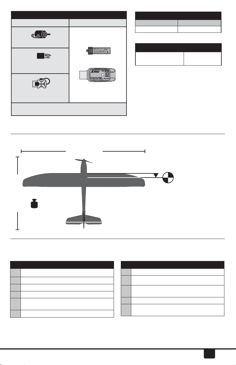
Box Contents
Installed Included
8.5mm Brushed Motor
DSM2®/DSMX® AS3X
Receiver/ESC
USB Li-Po
Charger
2 x (SPMSA2030L) on the
Required to Complete: DSM2/DSMX 4-Channel
Transmitter
board
Specifi cations
28.7 in (730mm)
Dual Rates
High Low
100 % 70%
Timer Settings
First Flight
8 Min.
To register your product online, go to
www.e-fl iterc.com
10 Min.
31mm
16.5 in (418mm)
1.50 oz (43 g)
Prefl ight Checklist
1. Read this manual thoroughly.
2. Remove and inspect the box contents.
3. Charge the fl ight battery.
4. Assemble the aircraft.
5. Install the fl ight battery in the aircraft
(once it has been fully charged).
6. Bind the aircraft to the transmitter.
The CG location is 31mm back from the leading edge
at the wing root. This has been determined with the
included 1S 150mAh 3.7V Li-Po battery installed in
the middle of the battery cavity. Balance the model on
the edge of a metal ruler to fi nd the Center of Gravity.
Place the ruler on the underside of the airframe.
7. Make sure linkages move freely.
8. Perform the Control Direction Test.
9. Adjust the fl ight controls and
transmitter.
10. Find a safe and open area.
11. Plan your fl ight appropriate for the
fl ying location.
EN
3
Page 4

Charging Warnings
The Battery Charger (EFLC1008) included with your
aircraft has been designed to safely charge the
Li-Po battery.
CAUTION: All instructions and warnings
must be followed exactly. Mishandling of Li-Po
batteries can result in a fi re, personal injury and/or
property damage.
• By handling, charging or using the included
Li-Po battery, you assume all risks associated
with lithium batteries.
• If at any time the battery begins to balloon or
swell, discontinue use immediately. If charging
or discharging, discontinue and disconnect.
Continuing to use, charge or discharge a battery
that is ballooning or swelling can result in fi re.
• Always store the battery at room temperature
in a dry area for best results.
• Always transport or temporarily store the
battery in a temperature range of 40–120º F
(5–49° C). Do not store the battery or model in a
car or direct sunlight. If stored in a hot car, the
battery can be damaged or even catch fi re.
• Always charge batteries away from
fl ammable materials.
Charging the Battery
Refer to the charging warnings. It is recommended
to charge the battery while you inspect the
aircraft. The fl ight battery will be required to
confi rm proper aircraft operation in future steps.
Battery Charging Process
• Always inspect the battery before charging.
• Always disconnect the battery after charging,
and let the charger cool between charges.
• Always constantly monitor the temperature
of the battery pack while charging.
• ONLY USE A CHARGER SPECIFICALLY DESIGNED
TO CHARGE LI-PO BATTERIES. Failure to charge
the battery with a compatible charger may
cause a fi re resulting in personal injury and/or
property damage.
• Never discharge Li-Po cells to below 3V
under load.
• Never cover warning labels with hook and
loop strips.
• Never leave charging batteries unattended.
• Never charge batteries outside
recommended levels.
• Never charge damaged batteries.
• Never attempt to dismantle or alter the charger.
• Never allow minors to charge battery packs.
• Never charge batteries in extremely hot or
cold places (recommended between 40–120° F
(5–49° C)) or place in direct sunlight.
SOLID RED LED
–Charging
USB Li-Po
Charger
DC Input:5.0V 350mA
DC Output:4.2V 300mA
LED OFF
–Charge
Complete
EFLC1008
NOTICE: Charge only batteries that are cool to the
touch and are not damaged. Look at the battery
to make sure it is not damaged e.g., swollen, bent,
broken or punctured.
1. Insert the charger into a USB port.
2. Properly connect the battery into the charger.
The end cap of the battery is specifi cally
designed to allow the battery to fi t into the
slot one way (usually with the label on the
battery facing outward) to prevent reverse
polarity connection. However, check for proper
alignment and polarity.
3. Always disconnect the fl ight battery from
the charger immediately upon completion of
charging.
CAUTION: Only use chargers specifi cally
designed to charge the included Li-Po
battery. Failure to do so could result in fi re,
causing injury or property damage.
CAUTION: Never exceed the recommended
charge rate.
4
EN
LED Indications
Charging a fully discharged (not over-discharged)
150mAh battery takes approximately 30–40
minutes.
CAUTION: Once charging is complete,
immediately remove the battery. Never
leave a battery connected to the charger.
CHARGING (Solid Red)........................
MAX CHARGE
(off ) ...............................
Page 5

Wing Installation
1. Slide the wing into the wing slot on the
fuselage until the holes line up with the screw
holes on the bottom.
2. Secure the wing using 2 screws.
3. Cut the loop tape (A) into 3 pieces and apply
them around the screws in the battery holder,
as shown.
A
Transmitter and Receiver Binding
Binding Procedure Reference Table
1. Refer to your transmitter instructions for binding to
a receiver.
2. Make sure the fl ight battery is disconnected from
the aircraft.
3. Ensure the transmitter is powered OFF.
4. Connect the fl ight battery to the aircraft. The
receiver LED will begin to fl ash (typically after 5
seconds).
5. Make sure the transmitter controls are at neutral
and the throttle is in the low position.
6. Put your transmitter into bind mode.
7. After 5 to 10 seconds, the receiver status LED will
become solid, indicating that the receiver is bound
to the transmitter. If the LED does not turn solid,
refer to the Troubleshooting Guide at the end of the
manual.
For subsequent fl ights, power ON the transmitter for 5
seconds before connecting the fl ight battery.
For a list of compatible DSM2/DSMX
transmitters, please visit www.bindnfl y.com.
CAUTION: When using a Futaba®
transmitter with a Spektrum DSM module, you
must reverse the throttle channel and rebind.
Refer to your Spektrum module manual for
binding and failsafe instructions. Refer to your
Futaba transmitter manual for instructions on
reversing the throttle channel.
EN
5
Page 6
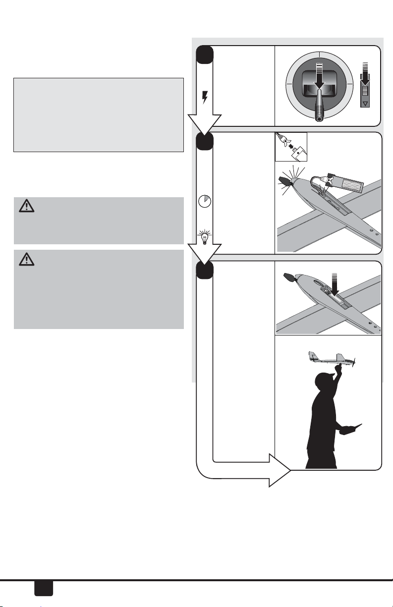
Installing the Flight Battery and Arming the ESC
Arming the ESC also occurs after binding as
previously described, but subsequent connection
of a fl ight battery requires the following steps.
AS3X
The AS3X® system will not activate until the
throttle stick or trim is increased for the fi rst
time. Once active, the control surfaces may
move rapidly and noisily on the aircraft.
This is normal. AS3X technology will remain
active until the battery is disconnected.
It is normal for linear servos to make noise. Noise
is not an indication of a faulty servo.
CAUTION: Always keep hands away
from the propeller. When armed, the motor will
turn the propeller in response to any throttle
movement.
CAUTION: Always disconnect the Li-Po
battery from the aircraft receiver when not
fl ying to avoid over-discharging the battery.
Batteries discharged to a voltage lower than
the lowest approved voltage may become
damaged, resulting in loss of performance and
potential fi re when batteries are charged.
Lower throttle and
1
throttle trim to
lowest settings.
Power ON the
transmitter, then
wait 5 seconds
Connect the
2
battery to the ESC,
noting proper
polarity.
Keep the plane
immobile and
away from wind
for 5 seconds.
Continuous LED
Secure the battery
3
to the hook and
loop strip on the
battery holder.
1-2-3-4-5 Sec.
FLY...
6
EN
Page 7

Control Direction Test
Move the controls on the transmitter to make sure the aircraft control surfaces move correctly. Always
keep throttle at the low position during testing.
Down
Elevator
Up
Elevator
Left
Rudder
Right
Rudder
Control Centering
Before fi rst fl ights, or in the event of a crash,
make sure the control surfaces are centered
when the transmitter controls and trims are
neutral. The transmitter sub-trim must be set
to zero. Adjust the linkages mechanically if the
control surfaces are not centered.
For best performance with AS3X, it is
important that excessive transmitter trim is
not used.
Control Horn Settings
Elevator
Rudder
EN
7
Page 8

Flying Tips
Consult local laws and ordinances before choosing
a location to fl y your aircraft.
We recommend fl ying your aircraft outside in no
greater than moderate winds or inside in a large
gymnasium. Always avoid fl ying near houses,
trees, wires and buildings. You should also be
careful to avoid fl ying in areas where there are
many people, such as busy parks, schoolyards or
soccer fi elds. For additional tips on fl ying, refer to
the product page at horizonhobby.com.
Hand Launching
When hand-launching your aircraft alone, hold
the aircraft in one hand and the transmitter in the
other.
Apply about 1/2–3/4 throttle. Hold the aircraft
on the underside and throw the aircraft directly
into the wind, angled slightly up (5 to 10 degrees
above the horizon). Climb to check the trim. Once
the trim is adjusted, begin exploring the fl ight
envelope of the aircraft.
Soaring
Your aircraft can ascend on thermals and other
updrafts to prolong its fl ight. There are many ways
to stay aloft with a sailplane, such as ridge lifts and
thermals. A thermal is simply a column of rising
warm air. Once you get your aircraft into the air,
watch your aircraft for a response to thermals.
If the airplane randomly rolls on its own, it is
likely that you only fl ew through the edge of the
thermal, causing one side of the airplane to rise,
rather than the entire airplane. Enter the thermal
by turning your aircraft directly into it, circling
to stay in the center of the thermal. Slow your
forward speed by increasing up elevator trim so
that your aircraft is moving just faster than stall
(minimum sink speed). Make easy banking turns
to fi nd the area of highest lift (the thermal’s core).
When you fi nd the core of lift, tighten your turns
to stay near this position. Sometimes thermals
drift downwind. It is best that you search for
thermals upwind, so that you can follow a thermal
downwind if it is pushed downwind.
With practice, you will fi nd it easier to locate and
anticipate the movement of thermals. Although
thermals cannot be seen, you can see dust, insects
or birds riding an updraft. Air movement of a
thermal may be felt, so movement in an otherwise
calm spot may show you the location of a nearby
thermal. A shift in the wind (in a light breeze) can
be airfl ow into a thermal.
Landing
Make sure to land into the wind. Due to the high
lifting effi ciency of the sailplane design, landing
requires a large landing area. While on your
downwind leg, remember that the sailplane glides
much better than other aircraft. You will need to
setup for landing lower and with a more shallow
descent than you may be used to. As you are on
approach for landing, ensure that the model is
descending slowly, but also not accelerating.
Maintain this descent and speed, and, as the
model nears the ground (approximately 6 inches
(15 cm)), slowly apply a small amount of up
elevator. Before the aircraft touches down, always
fully decrease throttle to avoid damage to the
propeller, motor, ESC or other components.
CAUTION: Never catch a fl ying aircraft in
your hands. Doing so could cause personal
injury and damage to the aircraft.
Failure to lower the throttle
stick and trim to the lowest
possible positions during
a crash could result in
damage to the ESC in the
receiver unit, which may
require replacement.
NOTICE: Crash damage
is not covered under
warranty.
NOTICE: Always
decrease throttle
at propeller strike.
8
EN
Page 9

Flying Tips continued
Low Voltage Cutoff (LVC)
Low Voltage Cutoff (LVC) pulses the power to the
motor when the voltage gets low. When the motor
power pulses, land the aircraft immediately and
recharge the fl ight battery.
Disconnect and remove the Li-Po battery from the
aircraft after use to prevent trickle discharge. Fully
charge your Li-Po battery before storing it. During
storage, make sure the battery charge does not
fall below 3V per cell.
LVC does not prevent the battery from overdischarge during storage.
NOTICE: Repeated fl ying to LVC will damage the
battery.
NOTICE: When fi nished fl ying, never keep the
aircraft in the sun. Do not store the aircraft in a
hot, enclosed area such as a car. Doing so can
damage the foam.
Post Flight Checklist
1. Disconnect the fl ight battery from the
ESC (required for safety and battery life).
2. Power OFF the transmitter.
3. Remove the fl ight battery from the
aircraft.
Repairs
Repair the aircraft using foam-compatible CA
glue (Cyanoacrylate adhesive) or clear tape. Only
use foam-compatible CA glue, as other types of
glue can damage the foam. When parts are not
repairable, or for a list of all replacement and
optional parts, refer to the list at the back of this
manual.
NOTICE: Use of foam-compatible CA accelerant
on your aircraft can damage paint. DO NOT handle
the aircraft until accelerant fully dries.
4. Recharge the fl ight battery.
5. Store the fl ight battery apart from the
aircraft and monitor the battery charge.
6. Make note of the fl ight conditions and
fl ight plan results, planning for future
fl ights.
EN
9
Page 10

Motor Service
CAUTION: DO NOT handle propeller parts
while the fl ight battery is connected. Personal
injury could result.
IMPORTANT: Removing tape or decals can
remove paint from the fuselage.
NOTICE: DO NOT remove the gearbox from
the aircraft. Damage to the aircraft will result.
• Hold the prop shaft using needle-nose pliers
or hemostats to remove the propeller and
prop nut.
Assembly
Assemble in reverse order.
• Correctly align the prop shaft gear with the
pinion gear on the motor.
• Connect the motor to the ESC/receiver so
that the powered motor turns the propeller
counterclockwise (facing the front of the
model).
• Make sure the propeller size numbers
• (130x70) face away from the motor (see
illustration).
• Attach the spinner to the propeller using foam-
compatible CA (Cyanoacrylate adhesive).
• Assemble the fuselage using clear tape.
R
e
m
o
v
e
I
n
s
t
a
l
l
10
EN
Page 11

Troubleshooting Guide
AS3X
Problem
Control surfaces
not at neutral position when transmitter controls are
at neutral
Model fl ies inconsistently from
fl ight to fl ight
Controls oscillate
in fl ight, (model
rapidly jumps or
moves)
Problem
Aircraft will
not respond to
throttle but responds to other
controls
Extra propeller
noise or extra
vibration
Reduced fl ight
time or aircraft
underpowered
Possible Cause Solution
Control surfaces may not have been
mechanically centered from factory
Aircraft was moved after the fl ight
battery was connected and before
sensors initialized
Trims are moved too far from neutral
position
Propeller is unbalanced, causing
excessive vibration
Nut on prop shaft is too loose, causing excessive vibration
Possible Cause Solution
Throttle stick and/or throttle trim is too
high
Throttle channel is reversed Reverse throttle channel on transmitter
Motor is disconnected from receiver Open fuselage and ensure the plug for
Damaged propeller, prop shaft or motor Replace damaged parts
Nut on prop shaft is too loose Tighten the prop shaft nut 1/2 turn
Flight battery charge is low Completely recharge fl ight battery
Propeller is installed backwards Install propeller with numbers facing
Flight battery is damaged Replace fl ight battery and follow fl ight
Flight conditions may be too cold Make sure battery is warm before use
Battery capacity is too low for fl ight
conditions
Center control surfaces mechanically by
adjusting the U-bends on control linkages
Disconnect and reconnect the fl ight
battery while keeping the aircraft still for
5 seconds
Neutralize trims and mechanically adjust
linkages to center control surfaces
Remove propeller and rebalance or
replace it if damaged
Tighten the prop shaft nut 1/2 turn
Reset controls with throttle stick and
throttle trim at lowest setting
the motor is properly installed
forward
battery instructions
Replace battery or use a larger capacity
battery
EN
11
Page 12

Troubleshooting Guide (continued)
Problem
LED on receiver
fl ashes rapidly
and aircraft will
not bind to
transmitter
(during binding)
LED on receiver
fl ashes rapidly
and aircraft will
not respond
to transmitter
(after binding)
Control surface
does not move
Controls
reversed
Motor loses
power
Motor power
quickly decreases and increases
then motor
loses power
Servo locks or
freezes at full
travel
Possible Cause Solution
Transmitter is too near aircraft during
binding process
Bind switch or button was not held
while transmitter was powered on
Aircraft or transmitter is too close to
large metal object, wireless source or
another transmitter
Less than a 5-second wait between fi rst
powering on transmitter and connecting fl ight battery to aircraft
Aircraft is bound to a diff erent model
memory (ModelMatch
Flight battery/transmitter battery
charge is too low
Transmitter may have been bound to a
diff erent model (or with a diff erent DSM
Protocol)
Aircraft or transmitter is too close to
large metal object, wireless source or
another transmitter
Control surface, control horn, linkage or
servo damage
Wire damaged or connections loose Do a check of wires and connections;
Flight battery charge is low Fully recharge fl ight battery
Control linkage does not move freely Make sure control linkage moves freely
Transmitter settings reversed Do the Control Direction Test and adjust
Damage to motor or power components Do a check of motor and power compo-
Nut on prop shaft is too tight Loosen prop shaft nut until propeller
Battery power is down to the point of
receiver/ESC Low Voltage Cutoff (LVC)
Travel adjust value is set above 100%
overdriving the servo
TM
radios only)
Power off transmitter, move transmitter a
larger distance from aircraft, disconnect
and reconnect fl ight battery to aircraft
and follow binding instructions
Power off transmitter and repeat bind
process
Move aircraft and transmitter to another
location and attempt binding again
Leaving transmitter on, disconnect and
reconnect fl ight battery to aircraft
Select correct model memory on transmitter and disconnect and reconnect
fl ight battery to aircraft
Replace/recharge batteries
Select the right transmitter or bind to the
new one
Move aircraft and transmitter to another
location and attempt connecting again
Replace or repair damaged parts and
adjust controls
connect or replace as needed
controls on transmitter appropriately
nents for damage (replace as needed)
shaft turns freely
Recharge fl ight battery or replace battery
that is no longer performing
Set Travel adjust to 100% or less and/or
set sub trims to Zero and adjust linkages
mechanically.
12
EN
Page 13

Limited Warranty
What this Warranty Covers
Horizon Hobby, Inc. (“Horizon”) warrants to the
original purchaser that the product purchased (the
“Product”) will be free from defects in materials
and workmanship at the date of purchase.
What is Not Covered
This warranty is not transferable and does
not cover (i) cosmetic damage, (ii) damage
due to acts of God, accident, misuse, abuse,
negligence, commercial use, or due to improper
use, installation, operation or maintenance, (iii)
modifi cation of or to any part of the Product, (iv)
attempted service by anyone other than a Horizon
Hobby authorized service center, (v) Product not
purchased from an authorized Horizon dealer,
or (vi) Product not compliant with applicable
technical regulations.
OTHER THAN THE EXPRESS WARRANTY ABOVE,
HORIZON MAKES NO OTHER WARRANTY OR
REPRESENTATION, AND HEREBY DISCLAIMS ANY
AND ALL IMPLIED WARRANTIES, INCLUDING,
WITHOUT LIMITATION, THE IMPLIED WARRANTIES
OF NON-INFRINGEMENT, MERCHANTABILITY
AND FITNESS FOR A PARTICULAR PURPOSE. THE
PURCHASER ACKNOWLEDGES THAT THEY ALONE
HAVE DETERMINED THAT THE PRODUC T WILL
SUITABLY MEET THE REQUIREMENTS OF THE
PURCHASER’S INTENDED USE.
Purchaser’s Remedy
Horizon’s sole obligation and purchaser’s sole
and exclusive remedy shall be that Horizon will,
at its option, either (i) service, or (ii) replace, any
Product determined by Horizon to be defective.
Horizon reserves the right to inspect any and all
Product(s) involved in a warranty claim. Service or
replacement decisions are at the sole discretion
of Horizon. Proof of purchase is required for all
warranty claims. SERVICE OR REPLACEMENT
AS PROVIDED UNDER THIS WARRANTY IS THE
PURCHASER’S SOLE AND EXCLUSIVE REMEDY.
Limitation of Liability
HORIZON SHALL NOT BE LIABLE FOR SPECIAL,
INDIRECT, INCIDENTAL OR CONSEQUENTIAL
DAMAGES, LOSS OF PROFITS OR PRODUCTION OR
COMMERCIAL LOSS IN ANY WAY, REGARDLESS OF
WHETHER SUCH CLAIM IS BASED IN CONTRACT,
WARRANTY, TORT, NEGLIGENCE, STRICT LIABILITY
OR ANY OTHER THEORY OF LIABILITY, EVEN IF
HORIZON HAS BEEN ADVISED OF THE POSSIBILITY
OF SUCH DAMAGES. Further, in no event shall
the liability of Horizon exceed the individual
price of the Product on which liability is asserted.
As Horizon has no control over use, setup, fi nal
assembly, modifi cation or misuse, no liability
shall be assumed nor accepted for any resulting
damage or injury. By the act of use, setup or
assembly, the user accepts all resulting liability.
If you as the purchaser or user are not prepared
to accept the liability associated with the use
of the Product, purchaser is advised to return
the Product immediately in new and unused
condition to the place of purchase.
Law
These terms are governed by Illinois law (without
regard to confl ict of law principals). This warranty
gives you specifi c legal rights, and you may also
have other rights which vary from state to state.
Horizon reserves the right to change or modify
this warranty at any time without notice.
WARRANTY SERVICES
Questions, Assistance, and Services
Your local hobby store and/or place of purchase
cannot provide warranty support or service. Once
assembly, setup or use of the Product has been
started, you must contact your local distributor
or Horizon directly. This will enable Horizon to
better answer your questions and service you in
the event that you may need any assistance. For
questions or assistance, please visit our website
at www.horizonhobby.com, submit a Product
Support Inquiry, or call the toll free telephone
number referenced in the Warranty and Service
Contact Information section to speak with a
Product Support representative.
Inspection or Services
If this Product needs to be inspected or serviced
and is compliant in the country you live and use
the Product in, please use the Horizon Online
Service Request submission process found on
our website or call Horizon to obtain a Return
Merchandise Authorization (RMA) number. Pack
the Product securely using a shipping carton.
Please note that original boxes may be included,
but are not designed to withstand the rigors of
shipping without additional protection. Ship via
a carrier that provides tracking and insurance
for lost or damaged parcels, as Horizon is not
responsible for merchandise until it arrives and is
accepted at our facility. An Online Service Request
is available at http://www.horizonhobby.com/
content/_service-center_render-service-center.
If you do not have internet access, please contact
Horizon Product Support to obtain a RMA number
along with instructions for submitting your
product for service. When calling Horizon, you will
be asked to provide your complete name, street
address, email address and phone number where
you can be reached during business hours. When
sending product into Horizon, please include
your RMA number, a list of the included items,
and a brief summary of the problem. A copy
of your original sales receipt must be included
for warranty consideration. Be sure your name,
address, and RMA number are clearly written on
EN
13
Page 14

the outside of the shipping carton.
NOTICE: Do not ship LiPo batteries to Horizon.
If you have any issue with a LiPo battery,
please contact the appropriate Horizon
Product Support offi ce.
Warranty Requirements
For Warranty consideration, you must include
your original sales receipt verifying the proofof-purchase date. Provided warranty conditions
have been met, your Product will be serviced or
replaced free of charge. Service or replacement
decisions are at the sole discretion of Horizon.
Non-Warranty Service
Should your service not be covered by
warranty, service will be completed and
payment will be required without notifi cation
or estimate of the expense unless the expense
exceeds 50% of the retail purchase cost. By
submitting the item for service you are agreeing
to payment of the service without notifi cation.
Service estimates are available upon request.
You must include this request with your item
submitted for service. Non-warranty service
estimates will be billed a minimum of ½ hour
of labor. In addition you will be billed for return
freight. Horizon accepts money orders and
cashier’s checks, as well as Visa, MasterCard,
American Express, and Discover cards. By
submitting any item to Horizon for service, you are
agreeing to Horizon’s Terms and Conditions found
on our website http://www.horizonhobby.com/
content/_service-center_render-service-center.
ATTENTION: Horizon service is limited to
Product compliant in the country of use and
ownership. If received, a non-compliant
Product will not be serviced. Further, the
sender will be responsible for arranging
return shipment of the un-serviced Product,
through a carrier of the sender’s choice and at
the sender’s expense. Horizon will hold noncompliant Product for a period of 60 days from
notifi cation, after which it will be discarded.
Warranty and Service Information
Country of
Purchase
United
States
of America
United
Kingdom
Germany
France
China
Horizon Hobby Phone Number/Email Address Address
Horizon Service Center
(Repairs and Repair Requests)
Horizon Product Support
(Product Technical Assistance)
Sales
Service/Parts/Sales:
Horizon Hobby Limited
Horizon Technischer Ser vice
Sales: Horizon Hobby GmbH
Service/Parts/Sales:
Horizon Hobby SAS
Service/Parts/Sales:
Horizon Hobby – China
servicecenter.horizonhobby.
com/RequestForm/
www.quickbase.com/db/
bghj7ey8c?a=GenNewRecord
888-959-2305
sales@horizonhobby.com
888-959-2305
sales@horizonhobby.co.uk
+44 (0) 1279 641 097
+49 (0) 4121 2655 100
service@horizonhobby.de
infofrance@horizonhobby.
com +33 (0) 1 60 18 34 90
info@horizonhobby.com.cn
+86 (021) 5180 9868
4105 Fieldstone Rd
Champaign, Illinois, 61822
USA
Units 1-4 Ployters Rd
Staple Tye Harlow, Essex
CM18 7NS, United
Kingdom
Christian-Junge-Straße 1
25337 Elmshorn, Germany
11 Rue Georges Charpak
77127 Lieusaint
Room 506,
No. 97 Changshou Rd.
Shanghai, China, 200060
FCC Information
This device complies with part 15 of the FCC rules. Operation is subject to the following two conditions:
(1)This device may not cause harmful interference, and (2) this device must accept any interference
received, including interference that may cause undesired operation.
CAUTION: Changes or modifi cations not expressly approved by the party responsible for
compliance could void the user’s authority to operate the equipment.
This product contains a radio transmitter with wireless technology which has been tested and found
to be compliant with the applicable regulations governing a radio transmitter in the 2.400GHz to
2.4835GHz frequency range.
14
EN
Page 15

Compliance Information for the European Union
Declaration of Conformity
(in accordance with ISO/IEC 17050-1)
No. HH2014010402
Product(s): EFL UMX Radian BNF
Item Number(s): EFLU2980
Equipment class: 1
The object of declaration described above is in conformity with the requirements of the specifi cations
listed below, following the provisions of the European R&TTE directive 1999/5/EC, EMC Directive
2004/108/EC and LVD Directive 2006/95/EC
EN 301 489-1 V1.9.2: 2012
EN 301 489-17 V2.1.1: 2009
EN60950-1:2006+A11:2009+A1:2010+A12: 2011
EN55022:2010 + AC:2011
EN55024: 2010
Signed for and on behalf of:
Horizon Hobby, Inc.
Champaign, IL USA
Jan 4, 2014
Chief Financial Offi cer
Instructions for disposal of WEEE by users in the European Union
Robert Peak
Horizon Hobby, Inc.
This product must not be disposed of with other waste. Instead, it is the user’s responsibility
to dispose of their waste equipment by handing it over to a designated collections point
for the recycling of waste electrical and electronic equipment. The separate collection and
recycling of your waste equipment at the time of disposal will help to conserve natural
resources and ensure that it is recycled in a manner that protects human health and the
environment. For more information about where you can drop off your waste equipment for recycling,
please contact your local city offi ce, your household waste disposal service or where you purchased
the product.
EN
15
Page 16

Replacement Parts • Ersatzteile • Pièces de rechange
• Pezzi di ricambio
Part # • Nummer
Numéro • Codice
EFLU2903
EFLU2901
EFLU2902
EFLU2920
EFLU2925
EFLU2967
EFLU2922
EFLB1501S25
SPMAR5430L
EFLU2916
Description Beschreibung Description Descrizione
Spinner Set (3):
Ultra Micro Radian
Decal Sheet: Ultra
Micro Radian
Folding Propeller:
Ultra Micro Radian
Main Wing: Ultra
Micro Radian
Tail Set: Ultra
Micro Radian
Fuselage: Ultra
Micro Radian
Pushrod Set: Ultra
Micro Radian
1S 3.7V 25C
150mAh Li-Po
Battery
5-CH Replacement
AS3X Receiver: UM
Radian
Motor: Ultra
Micro Radian
Ultra Micro Radian:
Spinner Set
E-fl ite Ultra
Micro Radian:
Dekorbogen
E-fl ite Ultra Micro
Radian KlappPropeller
Ultra Micro Radian:
Tragfl äche
E-fl ite Ultra Micro
Radian: Leitwerk
E-fl ite Ultra Micro
Radian: Rumpf
Ultra Micro Radian:
Schubstangensatz
1S-3,7V-25C
150mAh-Li-Po-Akku
E-fl ite UM Radian 5
Kanal Ersatz AS3X
Empfänger
E-fl ite Motor :
Micro Radian
Jeu de cônes (3) :
Ultra Micro Radian
Planche de
décalcomanies:
Ultra Micro Radian
Hélice repliable :
Ultra Micro Radian
Aile : Ultra Micro
Radian
Empennages : Ultra
Micro Radian
Fuselage : Ultra
Micro Radian
Jeu tringleries:
Ultra Micro Radian
Batterie Li-Po
150mAh 25C 3,7V
1S
Récepteur 5 voies
de remplacement
avec technologie
AS3X : UM Radian
Moteur: Ultra
Micro Radian
Set ogiva (3): Ultra
Micro Radian
Foglio con
decalcomanie: Ultra
Micro Radian
Elica ripiegabile:
Ultra Micro Radian
Ala Principale: Ultra
Micro Radian
Set coda: Ultra Micro
Radian
Fusoliera: Ultra
Micro Radian
Set asta di spinta:
Ultra Micro Radian
Batteria Li-Po 1S
da3,7V, 25C 150
mAh
Ricevente a 5-CH
con Sistema AS3X:
UM Radian
Motore Ultra Micro
Radian
EFLU2927
EFL9054
Gearbox: Ultra
Micro Radian
Prop Shaft with
gear (2) : Sukhoi
Su-26m, Micro
P-51
E-fl ite Getriebe :
Ultra Micro Radian
E-fl ite Ultra
Micro 4-Site
Luftschraubenwelle mit Getriebe
Réducteur : Ultra
Micro Radian
Arbre d’hélice
avec réducteur (2)
: Sukhoi Su-26m,
Micro P-51
Riduttore: Ultra
Micro Radian
Albero dell’elica
con ingranaggio
(2): Sukhoi Su-26m,
Micro P-51
57
Page 17

Optional Parts and Accessories • Optionale Bauteile und Zubehör •
Pièces et accessoires optionnels • Componenti e accessori opzionali
Part # | Nummer
Numéro | Codice
EFLC1000
EFLC1004
EFLB1501S45
EFLC1005/
AU/EU/UK
Description Beschreibung Description Descrizione
AC/DC 3.7V Li-Po
Charger
Celectra 4-Port 1S
3.7V 0.3 A DC Li-Po
Charger
150mAh 1S 3.7V
45C Li-Po Battery
AC to 6V DC 1.5
amp Power Supply
(Based upon your
sales Region)
DX4e DSMX
4-channel
Transmitter
DX5e DSMX
5-channel
Transmitter
DX6i DSMX 6-Channel Transmitter
DX7s DSMX 7-Channel Transmitter
DX8 DSMX
Transmitter
AC/DC-3,7V-Li-PoLadegerät
E-fl ite 4 Port Ladegerät 1S 3,7V 0,3A
1S 3.7V 150mAh 45C
Li-Po Akku
E-fl ite Netzteil für 4
Port Ladegerät
Spektrum DX4e
DSMX 4 Kanalsender
ohne Empfänger
Spektrum DX5e
DSMX 5 Kanalsender
ohne Empfänger
DX6i DSMX 6-Kanal
Sender
Spektrum DX7s
7 Kanal Sender
Spektrum DX8 nur
Sender
Chargeur Li-Po
CA/DC3,7V
Chargeur Li-Po
CC 0,3A 3,7V 1S
4ports Celectra
Batterie Li-Po
3.7V 1S 150mA
45C
Alimentation CA
vers 6 V CC, 1,5
A (En fonction
de votre région)
Emetteur DX4e
DSMX 4 voies
Emetteur DX5e
DSMX 5 voies
Emetteur DX6i
DSMX 6 voies
Emetteur DX7s
DSMX 7 voies
Emetteur DX8
DSMX 8 voies
Caricabatterie Li-Po
CA/CCda 3,7V
Caricabatterie Li-Po
1S da 3,7V 0,3 A CC,
a4porte, Celectra
1S 3.7V 150mAh 45C
Li-Po Batteria
Alimentatore da CA
a 6 V CC, 1,5 Amp
(in base al Paese di
vendita)
DX4e DSMX
Trasmettitore 4 canali
DX5e DSMX
Trasmettitore 5 canali
DX6i DSMX
Trasmettitore 6 canali
DX7s DSMX
Trasmettitore 7 canali
DX8 DSMX Solo
trasmettitore
Parts Contact Information • Kontaktinformationen für Ersatzteile •
Coordonnées (pièces) • Recapiti dei distributori
Country of
Purchase
United States Sales
United Kingdom
Germany Horizon Hobby GmbH
France Horizon Hobby SAS
China Horizon Hobby – China
Horizon Hobby Address
Horizon Hobby
Limited
58
4105 Fieldstone Rd
Champaign, Illinois, 61822 USA
Units 1-4 Ployters Rd
Staple Tye
Harlow, Essex
CM18 7NS, United Kingdom
Christian-Junge-Straße 1
25337 Elmshorn, Germany
11 Rue Georges Charpak
77127 Lieusaint, France
Room 506, No. 97 Changshou
Rd. Shanghai, China, 200060
Phone Number/
Email Address
800-338-4639
sales@horizonhobby.com
+44 (0) 1279 641 097
sales@horizonhobby.co.uk
+49 (0) 4121 2655 100
service@horizonhobby.de
+33 (0) 1 60 18 34 90
infofrance@horizonhobby.
com
+86 (021) 5180 9868
info@horizonhobby.com.cn
Page 18

© 2013 Horizon Hobby, Inc.
E-fl ite, Radian, AS3X, Blade, Celectra, UMX, DSM, DSM2, DSMX, ModelMatch, Bind-N-Fly, the Bind-N-Fly logo and the
Horizon Hobby logo are trademarks or registered trademarks of Horizon Hobby, Inc.
The Spektrum trademark is used with permission of Bachmann Industries, Inc.
Futaba is a registered trademark of Futaba Denshi Kogyo Kabushiki Kaisha Corporation of Japan.
All other trademarks, service marks and logos are property of their respective owners.
US D578, 146. US 7,898,130. PRC ZL 200720069025.2. PRC ZL 2007001249. Patents pending.
www.e-fl iterc.com
EFLU2980
Created 12/13 40111
 Loading...