

Page 1
UMX™ BEAST® 3D
Instruction Manual
Bedienungsanleitung
Manuel d’utilisation
Manuale di Istruzioni
Page 2
EN
NOTICE
All instructions, warranties and other collateral documents are subject to change at the sole discretion
of Horizon Hobby, Inc. For up-to-date product literature, visit www.horizonhobby.com and click on the
support tab for this product.
Meaning of Special Language
The following terms are used throughout the product literature to indicate various levels of potential
harm when operating this product:
NOTICE: Procedures, which if not properly followed, create a possibility of physical property damage AND
little or no possibility of injury.
CAUTION: Procedures, which if not properly followed, create the probability of physical property damage
AND a possibility of serious injury.
WARNING: Procedures, which if not properly followed, create the probability of property damage,
collateral damage, and serious injury OR create a high probability of superfi cial injury.
WARNING: Read the ENTIRE instruction manual to become familiar with the features of the product
before operating. Failure to operate the product correctly can result in damage to the product, personal
property and cause serious injury.
This is a sophisticated hobby product. It must be operated with caution and common sense and
requires some basic mechanical ability. Failure to operate this product in a safe and responsible
manner could result in injury or damage to the product or other property. This product is not intended
for use by children without direct adult supervision. Do not attempt disassembly, use with incompatible
components or augment product in any way without the approval of Horizon Hobby, Inc. This manual
contains instructions for safety, operation and maintenance. It is essential to read and follow all the
instructions and warnings in the manual, prior to assembly, setup or use, in order to operate correctly
and avoid damage or serious injury.
Age Recommendation: Not for children under 14 years. This is not a toy.
2
Page 3
Designed by aerobatic world champion Quique Somenzini, the Ultra Micro extreme (UMX) Beast® 3D BNF
Basic is a thrilling small-scale recreation of one of the most awe-inspiring airplanes ever created. At its
heart is the revolutionary AS3X
to fl y indoors, and handle windy conditions outdoors. The added punch of its stronger 2500Kv, 180BL
outrunner motor delivers an outstanding thrust to weight ratio. But beyond the capability to better perform
all-out 3D, you will fi nd that the Beast 3D with AS3X gives you unmatched precision in its size-class and
remarkably stable handling. Surprisingly, all of the performance possible from the UMX
Basic only requires basic radio programming. And even though your new model is fully assembled, please
read and follow this manual completely to be sure you’re ready to take full advantage of what this awesome
RC aircraft has to offer.
™
System built in to help provide you with a true 3D experience, the ability
™
Beast 3D BNF
Table of Contents
Specifi cations .......................................................3
Prefl ight Checklist .................................................4
™
AS3X
Stabilization ..............................................4
Low Voltage Cutoff (LVC) .......................................4
Transmitter and Receiver Binding ..........................5
Installing the Flight Battery ...................................5
Arming the ESC ....................................................6
Control Direction Test ............................................6
Control Centering .................................................6
Settings for Control Horns .....................................7
Dual Rates ............................................................7
Adjusting Center of Gravity (CG) ............................7
Flying Tips and Repairs .........................................8
Additional Safety Precautions and Warnings ..........9
Service of Power Components ............................10
Troubleshooting Guide ........................................11
Troubleshooting Guide (Continued) ......................12
Warranty and Repair Policy .................................13
Warranty and Service Information .......................14
Compliance Information for the European Union ..14
Parts Contact Information ...................................54
Replacement Parts ..............................................54
Optional Replacement Parts ................................55
EN
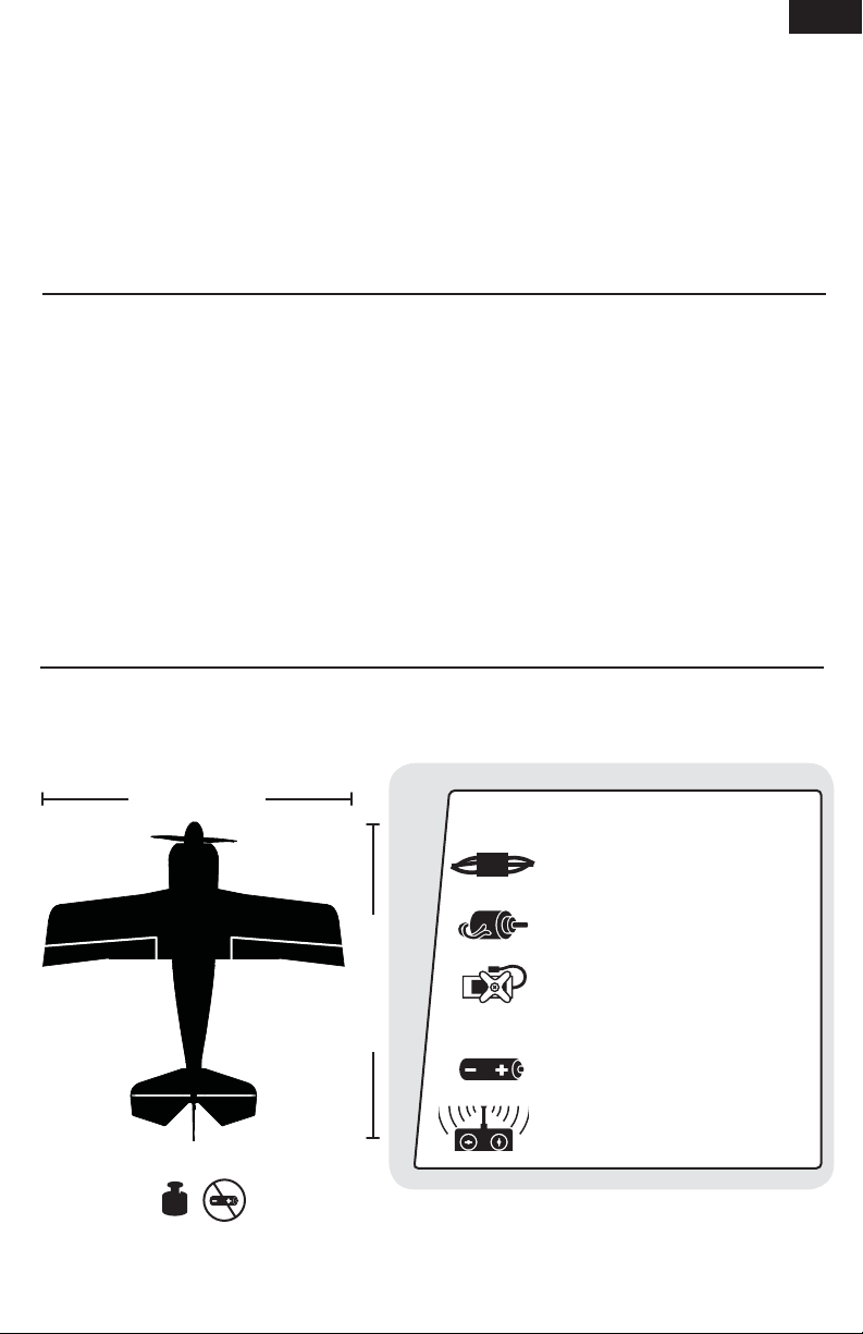
Specifi cations
14.7 in (372mm)
Installed
EFLU4864 DSM2 6Ch Ultra Micro
AS3X Receiver BL-ESC
BL180 Brushless Outrunner
Motor, 2500Kv
(4) 2.3 g Performance Linear Long
Throw Servo
15.7 in (400mm)
2.0 oz (58 g)
To register your product online, go to www.e-fliterc.com
Needed to Complete
Battery: 180mAh 2S 20C Li-Po
Battery Charger: 2S 7.4V Li-Po
Recommended Transmitter:
Spektrum™ DSM2™/DSMX® full range
with dual-rates (DX4e and up)
3
Page 4

EN
Prefl ight Checklist
1. Charge fl ight battery.
2. Install fl ight battery in the aircraft
(once it has been fully charged).
3. Bind aircraft to your transmitter.
4. Make sure linkages move freely.
5. Perform Control Direction Test with
the transmitter.
AS3X™ Stabilization
DELIVERS BREAKTHROUGH PERFORMANCE
The AS3X System for airplanes is an electronic
enhancement system that makes it possible for you
to experience super-smooth fl ight performance, yet
still have full control authority for sport, scale or 3D
fl ight.
Turbulence, torque and tip stalls are just some of
the many complications to assess when trying to
achieve smooth fl ight. The Horizon Hobby worldclass team of RC pilots developed the AS3X System
for airplanes based on the successful use of AS3X
with ultra micro fl ybarless helicopters. The AS3X
System invisibly helps with complicated corrections,
6. Adjust fl ight controls and transmitter.
7. Perform a radio system Range Check.
8. Find a safe and open area.
9. Plan fl ight for fl ying fi eld conditions.
allowing you to experience ultra-smooth fl ight
performance that feels so natural that you’ll quickly
build confi dence in the capability of the airplane.
AS3X system setup is easy. Just bind your DSM2
®
DSMX
transmitter to the model using a basic
airplane program and AS3X will assure that the
locked-in feel and control authority you want is
instantly at your command to help show off your RC
pilot skills.
AS3X will innovate the way you’ll want to fl y now
and in the future. To see what we mean, go to
www.E-fl iteRC.com/AS3X.
™
/
Low Voltage Cutoff (LVC)
When a Li-Po battery is discharged below 3V per
cell, it will not hold a charge. The Beast 3D ESC
protects the fl ight battery from over-discharge using
Low Voltage Cutoff (LVC). Before the battery charge
decreases too much, LVC removes power supplied
to the motor. Power to the motor quickly decreases
and increases, showing that some battery power is
reserved for fl ight control and safe landing.
When the motor power pulses, land the aircraft
immediately and recharge the fl ight battery.
Disconnect and remove the Li-Po battery from the
aircraft after use to prevent trickle discharge. Before
storage, charge the Li-Po battery to full capacity.
4
During storage, make sure the battery charge does
not fall below 3V per cell.
Tip: Due to the quiet nature of the aircraft, you may
not hear the pulsing of the motor.
For your fi rst fl ights, set your transmitter timer or
a stopwatch to fi ve minutes. Adjust your timer for
longer or shorter fl ights once you have fl own the
model.
NOTICE: Repeated fl ying to LVC will damage
the battery.
Page 5
Transmitter and Receiver Binding
Binding is the process of programming the receiver of the control unit to recognize the GUID (Globally
Unique Identifi er) code of a single specifi c transmitter. You need to ‘bind’ your chosen SpektrumTM DSM2
®
DSMX
technology equipped aircraft transmitter to the receiver for proper operation.
Any JR® or Spektrum DSM2/DSMX transmitter can bind to the EFLU4864 receiver. Due to the aerobatic
capabilities of the UMX Beast 3D, it is highly recommended that you use a transmitter with dual rates. Please
visit www.bindnfl y.com for a complete list of compatible transmitters.
NOTICE: When using a Futaba® transmitter with a Spektrum DSM module, reversing the throttle channel is
required.
Binding Procedure
1. Refer to your transmitter’s unique instructions for binding to a receiver.
2. Make sure the fl ight battery is disconnected from the aircraft.
3. Power off your transmitter.
4. Connect the fl ight battery in the aircraft. The receiver LED will begin to fl ash rapidly. (Typically after 5 seconds).
5. Make sure transmitter controls are neutral and throttle and throttle trim are in low position.
6. Put your transmitter into bind mode. Refer to your transmitter’s manual for binding button or switch instructions.
7. After fi ve to 10 seconds, the receiver status LED will become solid, indicating that the receiver is bound to the
transmitter. If the LED does not turn solid, refer to Troubleshooting Guide at back of manual.
For subsequent fl ights, power on the transmitter for 5 seconds before connecting the fl ight battery.
TM
/
Installing the Flight Battery
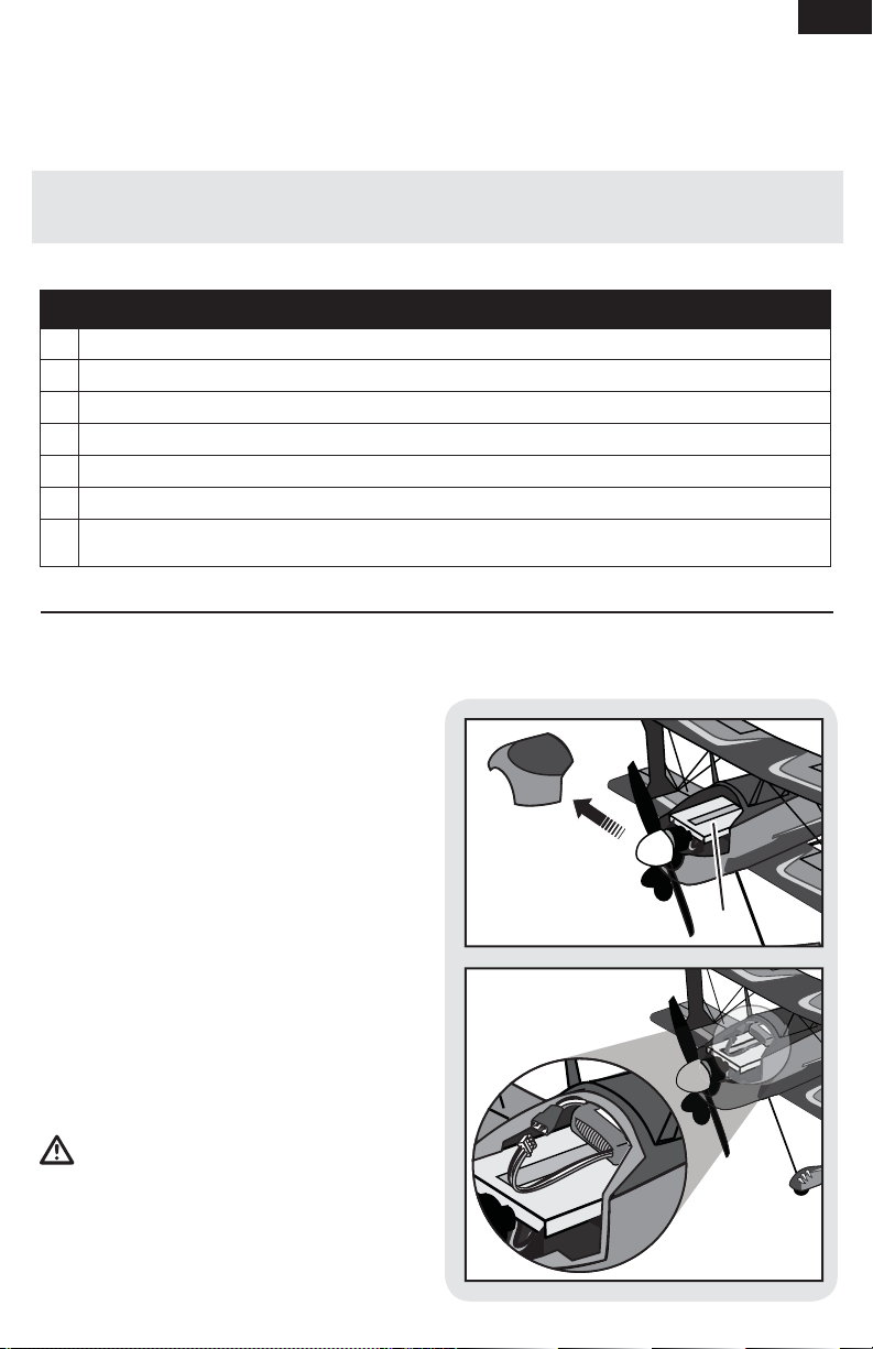
EN
1. Remove the battery hatch from the nose of the
aircraft.
2. Attach the flight battery to the hook and loop
strip (A) on the battery tray. See the Adjusting
the Center of Gravity instructions for the
battery’s position.
3. Place the aircraft on the ground out of the
wind and connect a fully charged flight battery.
Ensure the aircraft is immobile for 5
seconds so the AS3X system initializes
correctly. See the Arming the ESC instructions
for correct connection of the battery to
the ESC.
4. Install the battery hatch.
NOTICE: If using a different battery than the
recommended 2-Cell 7.4V 180mAh 20C Li-Po, you
will need to apply a circle of hook and loop fastener
to the back of the battery, opposite the side with
the label, in order to hold the battery in place.
CAUTION: Always disconnect the Li-Po
battery from the aircraft receiver when not fl ying to
avoid over-discharging the battery. Batteries
discharged to a voltage lower than the lowest
approved voltage may become damaged, resulting
in loss of performance and potential fi re when
batteries are charged.
A
5
Page 6

EN
Arming the ESC
1 2
Lower throttle and throttle
trim to lowest settings.
Power on the Transmitter
then wait 5 seconds.
If you accidentally connect the battery while the throttle is fully raised, the ESC will enter programming
mode. Disconnect the battery immediately.
The AS3X system will not activate until the throttle stick or trim is increased for the fi rst time. Once the AS3X
is active, the control surfaces may move rapidly on the aircraft. This is normal.
AS3X will remain active until the battery is disconnected.
CAUTION: Always keep hands away from the propeller. When armed, the motor will turn the propeller
in response to any throttle movement.
Install fl ight battery and
connect it to the ESC.
3
Keep plane immobile
on its wheels away from
wind for fi ve seconds.
Series of tones
Continuous LED
Control Direction Test
You should bind your aircraft and transmitter before doing these tests. Move the controls on the transmitter
to make sure the aircraft control surfaces move correctly and in the proper direction.
Make sure all linkages move freely and that paint or decals are not adhered to them.
Control Centering
Before fi rst fl ights, or in the event of an accident,
make sure the fl ight control surfaces are centered.
Adjust linkages mechanically if the control surfaces
are not centered.
For best performance with AS3X, it is important that
excessive trim is not used. If the model requires
excessive trim, adjust the linkages and return the
trim on the transmitter to neutral position.
Use of the transmitter sub-trims will not correctly
center the aircraft control surfaces due to the
mechanical limits of the linear servos.
1. Make sure the control surfaces are neutral
when the transmitter controls and trims are
centered. The transmitter sub-trim must be set
to zero.
6
2. When needed, use a pair of pliers to carefully
bend the metal of the control linkage (see
illustration).
3. Make the U-shape narrower to make the
connector shorter. Make the U-shape wider
to make the linkage longer.
Page 7

Settings for Control Horns
The following illustrations show linkage positions
chosen for the most balanced aerobatic response.
Linkage connections on the control horns directly
affect aircraft response.
CAUTION: Extreme 3D fl ying is for advanced
modelers. Using this setting without proper
experience, could result in loss of control of your
aircraft and a crash, causing damage to the aircraft
and personal injury.
Dual Rates
INTERMEDIATE 3D FLYING
EXTREME 3D FLYING
Aileron Elevator Rudder
EXTREME
EXTREME
EN
We recommend using a DSM radio capable of dual
rates due to the aerobatic capabilities of the Beast
3D. The settings below are recommended starting
settings. Adjust according to individual preferences
after the initial fl ight.
High Rate Low Rate
Aileron 100% 70%
Elevator 100% 70%
Rudder 100% 70%
Adjusting Center of Gravity (CG)
The CG location is 19mm back from the leading
edge of the bottom wing at the root.
This CG location has been determined with the 2S
180mAh 7.4V Li-Po battery installed with the front
edge of the battery aligned or slightly forward of the
rear edge of the cowl.
NOTICE: DO NOT SET YOUR TRANSMITTER
TRAVEL ADJUST OVER 100%. If the TRAVEL
ADJUST is set over 100% it will not result in more
control movement; it will overdrive the servo and
cause damage.
It is normal for linear servos to make noise. Noise is
not an indication of a faulty servo.
The oversized battery tray allows for Center of
Gravity adjustment. Start by placing the front edge
of the battery aligned with or slightly forward of
the rear edge of the cowl. Adjust as needed by
sliding the battery back or forward. The wire length
provides for either front-facing or rear-facing
battery connection.
19mm
7
Page 8

EN
Flying Tips and Repairs
Flying
While the Beast 3D may be fl own indoors in an open
space such as a gymnasium, we recommend fl ying
your Beast 3D outside in no greater than moderate
winds. Always avoid fl ying near houses, trees,
wires and buildings. You should also be careful to
avoid fl ying in areas where there are many people,
such as busy parks, schoolyards or soccer fi elds.
Consult local laws and ordinances before choosing a
location to fl y your aircraft.
Place the Beast 3D in position for takeoff (facing into
the wind if fl ying outdoors). Set dual rates to low
position and gradually increase the throttle to ¾ to
full and steer with the rudder. Pull back gently on
the elevator and climb to check trim. Once the trim
is adjusted, begin exploring the fl ight envelope of
the Beast 3D.
Failure to lower the throttle
stick and trim to the lowest
possible positions during a
crash could result in damage
to the ESC in the receiver
unit, which may require
replacement.
The Beast 3D is equipped
with Over Current Protection
(OCP). This feature protects
the ESC from overheating.
OCP stops the motor when the transmitter throttle
is set too high and the propeller cannot turn. The
OCP will only activate when the throttle stick is
positioned just above 1/2 throttle. After the ESC
stops the motor, fully lower the throttle to re-arm
the ESC.
NOTICE: Crash damage is not covered under
warranty.
Repairs
Repair the Beast 3D using foam-compatible CA
(cyanocrylate adhesive) or clear tape. Only use
foam-compatible CA, as other types of glue can
damage the foam. When parts are not repairable,
see the Replacement Parts List for ordering by
item number.
For a listing of all replacement and optional parts,
refer to the list at the back of this manual.
NOTICE: Use of foam-compatible CA accelerant
on your model can damage paint. DO NOT handle
model until accelerant fully dries.
Always
decrease throttle at
propeller strike.
8
Page 9

Additional Safety Precautions and Warnings
EN
As the user of this product, you are solely
responsible for operating in a manner that does
not endanger yourself and others or result in
damage to the product or the property of others.
• Always keep a safe distance in all directions
around your model to avoid collisions or injury.
• Always operate your model in open spaces away
from full-size vehicles, traffi c and people.
• Always carefully follow the directions and
warnings for this and any optional support
equipment (chargers, rechargeable battery
packs, etc.).
• Always keep all chemicals, small parts and
anything electrical out of the reach of children.
Post Flight Checklist
1. Disconnect fl ight battery from ESC
(Required for Safety and battery life).
2. Power off transmitter.
3. Remove fl ight battery from aircraft.
4. Recharge fl ight battery.
This model is controlled by a radio signal subject
to interference from many sources outside your
control. This interference can cause momentary loss
of control, so it is advisable to always keep a safe
distance in all directions around your model, as this
space will help avoid collisions or injury.
• Always avoid water exposure to all equipment
not specifi cally designed and protected for this
purpose. Moisture causes damage to electronics.
• Never place any portion of the model in your
mouth as it could cause serious injury or
even death.
• Never operate your model with low transmitter
batteries.
5. Store fl ight battery apart from aircraft
and monitor the battery charge.
6. Make note of fl ight conditions and
fl ight plan results, planning for
future fl ights.
9
Page 10

EN
Service of Power Components
Disassembly
CAUTION: DO NOT handle propeller parts
while the fl ight battery is connected. Personal
injury could result.
Propeller
1. Remove the battery hatch by gripping the
front of the hatch, then pulling it up and
away from the fuselage.
2. Carefully loosen screw (A) inside the spinner,
then remove the propeller assembly (B) from
the motor shaft (C).
3. Remove the spinner (D) and glue from the
backplate (E) to free the propeller (F) and
backplate. The motor magnet may attract
screws to the motor.
Motor and Firewall
1. Remove 2 screws (G), the firewall (H) and
motor (I) from the fuselage motor
mount (J).
B
C
A
FDE
I
H
2. Remove the top screw (K) from the
firewall (H) and motor (I).
3. Disconnect the motor wire connector from
the ESC/receiver connector.
Assembly
Motor and Firewall
1. Connect the motor wire connector to the
ESC/receiver connector so the wire
colors align.
2. Install the motor in the firewall using a screw
in the top of the firewall.
3. Attach the firewall to the fuselage motor
mount using 2 screws.
Propeller
1. Install the backplate and propeller on the
motor shaft using a screw. The numbers on the
propeller must face out from the fuselage for
correct propeller operation.
2. Install the spinner on the propeller and
backplate using foam-compatible CA.
3. Put the foam battery hatch on the fuselage and
slide it back to fully engage the fuselage.
G
K
H
J
I
When the fuselage must be opened for access to
servos or receiver, first cut the tape or decals before
opening the canopy hatch.
Removing tape or decals may remove paint from
the fuselage.
10
Page 11

Troubleshooting Guide
AS3X
Problem Possible Cause Solution
Control surfaces are
not at neutral position
when transmitter
controls are at neutral
Model fl ies inconsistently from fl ight
to fl ight
Problem Possible Cause Solution
Aircraft will not
respond to throttle
but responds to other
controls
Extra propeller noise
or extra vibration
Reduced fl ight time
or aircraft underpowered
LED on receiver
fl ashes and aircraft
will not bind to
transmitter (during
binding)
LED on receiver
fl ashes rapidly and
aircraft will not
respond to transmitter (after binding)
Control surfaces may not have been
mechanically centered from factory
Aircraft was moved after the fl ight battery
was connected and before sensors
initialized
Trims are moved too far from neutral
position
Throttle stick and/or throttle trim too high Reset controls with throttle stick and throttle
Throttle channel is reversed Reverse throttle channel on transmitter
Motor disconnected from receiver Open fuselage and make sure motor is
Damaged propeller, spinner or motor Replace damaged parts
Prop screw is too loose Tighten the prop screw
Flight battery charge is low Completely recharge fl ight battery
Propeller installed backwards Install propeller with numbers facing forward
Flight battery damaged Replace fl ight battery and follow fl ight battery
Flight conditions may be too cold Make sure battery is warm before use
Battery capacity too low for fl ight conditions Replace battery or use a larger capacity battery
Transmitter too near aircraft during binding
process
Bind switch or button not held long enough
during bind process
Less than a 5-second wait between fi rst
powering on transmitter and connecting
fl ight battery to aircraft
Aircraft bound to different model memory
(ModelMatch
Flight battery/transmitter battery charge is
too low
TM
radios only)
Center control surfaces mechanically by
adjusitng the U-bends on control linkages
Disconnect fl ight battery and reconnect while
being sure model does not move for 5 seconds
Neutralize trims and mechanically adjust
linkages to center control surfaces
trim at lowest setting
connected to the receiver
instructions
Power off transmitter, move transmitter a larger
distance from aircraft, disconnect and reconnect fl ight battery to aircraft and follow binding
instructions
Power off transmitter and repeat bind process.
Hold transmitter bind button or switch until
receiver is bound
Leave transmitter on, disconnect and reconnect
fl ight battery to aircraft
Select correct model memory on transmitter
and disconnect and reconnect fl ight battery to
aircraft
Replace/recharge batteries
EN
11
Page 12

EN
Troubleshooting Guide (Continued)
Problem Possible Cause Solution
Control surface does
not move
Controls reversed Transmitter settings reversed Perform Control Direction Test and adjust
Motor loses power Damage to motor or power components Check motor and power components for
Motor power quickly
decreases and
increases then motor
loses power
Motor/ESC is not
armed after landing
Servo locks or freezes
at full travel
Control surface, control horn, linkage or
servo damage
Wire damaged or connections loose Check wires and connections, connect or
Flight battery charge is low Fully recharge fl ight battery
Control linkage does not move freely Make sure control linkage moves freely
Battery power is down to the point of
receiver/ESC Low Voltage Cutoff (LVC)
Over Current Protection (OCP) stops the
motor when the transmitter throttle is set
high and the propeller cannot turn
Travel adjust value is set above 100%
overdriving the servo
Replace or repair damaged parts and adjust
controls
replace as needed
controls on transmitter appropriately
damage (replace as needed)
Recharge fl ight battery or replace battery that
is no longer performing
Fully lower throttle and throttle trim to arm ESC
Set Travel adjust to 100% or less and/or set
sub-trims to Zero and adjust linkages
mechanically.
12
Page 13

Warranty and Repair Policy
What this Warranty Covers
Horizon Hobby, Inc. (“Horizon”) warrants to the original
purchaser that the product purchased (the “Product”) will
be free from defects in materials and workmanship at the
date of purchase.
What is Not Covered
This warranty is not transferable and does not cover (i)
cosmetic damage, (ii) damage due to acts of God,
accident, misuse, abuse, negligence, commercial use,
or due to improper use, installation, operation or
maintenance, (iii) modifi cation of or to any part of the
Product, (iv) attempted service by anyone other than a
Horizon Hobby authorized service center, or (v) Products
not purchased from an authorized Horizon dealer.
OTHER THAN THE EXPRESS WARRANTY ABOVE, HORIZON
MAKES NO OTHER WARRANTY OR REPRESENTATION, AND
HEREBY DISCLAIMS ANY AND ALL IMPLIED WARRANTIES,
INCLUDING, WITHOUT LIMITATION, THE IMPLIED WARRANTIES OF NON-INFRINGEMENT, MERCHANTABILITY AND
FITNESS FOR A PARTICULAR PURPOSE. THE PURCHASER
ACKNOWLEDGES THAT THEY ALONE HAVE DETERMINED
THAT THE PRODUCT WILL SUITABLY MEET THE REQUIREMENTS OF THE PURCHASER’S INTENDED USE.
Purchaser’s Remedy
Horizon’s sole obligation and purchaser’s sole and
exclusive remedy shall be that Horizon will, at its option,
either (i) service, or (ii) replace, any Product determined
by Horizon to be defective. Horizon reserves the right
to inspect any and all Product(s) involved in a warranty
claim. Service or replacement decisions are at the sole
discretion of Horizon. Proof of purchase is required for
all warranty claims. SERVICE OR REPLACEMENT AS
PROVIDED UNDER THIS WARRANTY IS THE PURCHASER’S
SOLE AND EXCLUSIVE REMEDY.
Limitation of Liability
HORIZON SHALL NOT BE LIABLE FOR SPECIAL, INDIRECT,
INCIDENTAL OR CONSEQUENTIAL DAMAGES, LOSS OF
PROFITS OR PRODUCTION OR COMMERCIAL LOSS IN ANY
WAY, REGARDLESS OF WHETHER SUCH CLAIM IS BASED
IN CONTRACT, WARRANTY, TORT, NEGLIGENCE, STRICT
LIABILITY OR ANY OTHER THEORY OF LIABILITY, EVEN IF
HORIZON HAS BEEN ADVISED OF THE POSSIBILITY OF
SUCH DAMAGES. Further, in no event shall the liability
of Horizon exceed the individual price of the Product on
which liability is asserted. As Horizon has no control over
use, setup, final assembly, modification or misuse, no
liability shall be assumed nor accepted for any resulting
damage or injury. By the act of use, setup or assembly,
the user accepts all resulting liability. If you as the purchaser or user are not prepared to accept the liability
associated with the use of the Product, purchaser is
advised to return the Product immediately in new and
unused condition to the place of purchase.
Law
These terms are governed by Illinois law (without regard to
conflict of law principals). This warranty gives you specific
legal rights, and you may also have other rights which vary
from state to state. Horizon reserves the right to change or
modify this warranty at any time without notice.
Warranty Services
Questions, Assistance, and Services
Your local hobby store and/or place of purchase cannot
provide mwarranty support or service. Once assembly,
EN
setup or use of the Product has been started, you must
contact your local distributor or Horizon directly. This will
enable Horizon to better answer your questions and
ervice you in the event that you may need any assistance.
For questions or assistance, please direct your email to
productsupport@ horizonhobby.com, or call 877.504.0233
toll free to speak to a Product Support representative. You
may also find information on our website at
www.horizonhobby.com.
Inspection or Services
If this Product needs to be inspected or serviced, please
use the Horizon Online Service Request submission
process found on our website or call Horizon to obtain a
Return Merchandise Authorization (RMA) number. Pack
the Product securely using a shipping carton. Please note
that original boxes may be included, but are not designed
to withstand the rigors of shipping without additional
protection. Ship via a carrier that provides tracking and
insurance for lost or damaged parcels, as Horizon is
not responsible for merchandise until it arrives and is
accepted at our facility. An Online Service Request is
available at www.horizonhobby.com under the Support
tab. If you do not have internet access, please contact
Horizon Product Support to obtain a RMA number along
with instructions for submitting your product for service.
When calling Horizon, you will be asked to provide your
complete name, street address, email address and phone
number where you can be reached during business hours.
When sending product into Horizon, please include your
RMA number, a list of the included items, and a brief summary of the problem. A copy of your original sales receipt
must be included for warranty consideration. Be sure your
name, address, and RMA number are clearly written on
the outside of the shipping carton.
Notice: Do not ship LiPo batteries to Horizon. If you
have any issue with a LiPo battery, please contact the
appropriate Horizon Product Support office.
Warranty Requirements
For Warranty consideration, you must include your
original sales receipt verifying the proof-ofpurchase date. Provided warranty conditions have
been met, your Product will be serviced or replaced
free of charge. Service or replacement decisions are
at the sole discretion of Horizon.
Non-Warranty Service
Should your service not be covered by warranty
service will be completed and payment will be
required without notification or estimate of the
expense unless the expense exceeds 50% of the
retail purchase cost. By submitting the item for service
you are agreeing to payment of the service without
notification. Service estimates are available upon request.
You must include this request with your item submitted
for service. Non-warranty service estimates will be billed
a minimum of ½ hour of labor. In addition you will be
billed for return freight. Horizon accepts money orders and
cashiers checks, as well as Visa, MasterCard, American
Express, and Discover cards. By submitting any item to
Horizon for service, you are agreeing to Horizon’s Terms
and Conditions found on our website www.horizonhobby.
com/Service/Request/.
13
Page 14

EN
Warranty and Service Information
Country of
Purchase
United States
of America
United Kingdom Horizon Hobby Limited
Germany
France Horizon Hobby SAS
Horizon Hobby Address Phone Number/Email Address
Horizon Service Center
(Electronics and engines)
Horizon Product Support
(All other products)
Horizon Technischer
Service
4105 Fieldstone Rd
Champaign, Illinois
61822 USA
4105 Fieldstone Rd
Champaign, Illinois
61822 USA
Units 1-4 Ployters Rd
Staple Tye
Harlow, Essex
CM18 7NS
United Kingdom
Christian-Junge-Straße 1
25337 Elmshorn
Germany
14 Rue Gustave Eiffel
Zone d’Activité du Réveil Matin
91230 Montgeron
877-504-0233
Online Repair Request visit:
www.horizonhobby.com/service
877-504-0233
productsupport@horizonhobby.com
+44 (0) 1279 641 097
sales@horizonhobby.co.uk
+49 (0) 4121 2655 100
service@horizonhobby.de
+33 (0) 1 60 47 44 70
infofrance@horizonhobby.com
Compliance Information for the European Union
Declaration of Conformity
(in accordance with ISO/IEC 17050-1)
No. HH2011093005
Product(s): UMX Beast 3D BNF Basic
Item Number(s): EFLU4850
Equipment class: 1
The object of declaration described above is in conformity with the requirements of the specifications listed
below, following the provisions of the European R&TTE directive 1999/5/EC:
EN 301 489-1 V1.7.1: 2006
EN 301 489-17 V1.3.2: 2008
Steven A. Hall
Signed for and on behalf of:
Horizon Hobby, Inc.
Champaign, IL USA
International Operations and Risk Management
Vice President
Horizon Hobby, Inc.
Sep 30, 2011
Instructions for disposal of WEEE by users in the European Union
This product must not be disposed of with other waste. Instead, it is the user’s responsibility
to dispose of their waste equipment by handing it over to a designated collections point
for the recycling of waste electrical and electronic equipment. The separate collection and
recycling of your waste equipment at the time of disposal will help to conserve natural
environment. For more information about where you can drop off your waste equipment for recycling, please
contact your local city offi ce, your household waste disposal service or where you purchased the product.
resources and ensure that it is recycled in a manner that protects human health and the
14
Page 15

– Parts Contact Information –
– Intaktinformationen für Ersatzteile –
– Coordonnés pour obtenir de piéces détachées –
– Recapiti per i ricambi –
Country of Purchase Horizon Hobby Address Phone Number/Email Address
United States Sales
United Kingdom Horizon Hobby Limited
Germany Horizon Hobby GmbH
France Horizon Hobby SAS
4105 Fieldstone Rd
Champaign, Illinois, 61822 USA
Units 1-4 Ployters Rd
Staple Tye
Harlow, Essex
CM18 7NS, United Kingdom
Christian-Junge-Straße 1, 25337
Elmshorn, Germany
14 Rue Gustave Eiffel
Zone d’Activité du Réveil Matin
91230 Montgeron
800-338-4639
sales@horizonhobby.com
+44 (0) 1279 641 097
sales@horizonhobby.co.uk
++49 (0) 4121 2655 100
service@horizonhobby.de
+33 (0) 1 60 47 44 70
infofrance@horizonhobby.com
– Replacement Parts –
– Ersatzteile –
– Piéces de rechange –
– Ricambi –
Part # • Nummer
Numéro • Codice
EFLU4859
EFLU4064
EFLU4858
EFLU4860
EFLU4854
EFLU4055
EFLU4862
EFLU4865
EFLU4863
EFLUP0503
EFLUM180BL2
EFLUB1802S20
EFLU4851
54
Description Beschreibung Description Descrizione
Wing Set: UMX
Beast 3D
Cabane: UMX Beast Tragfl ächenstreben:
Fuselage Set: UMX
Beast 3D
Tail Surface set:
UMX Beast 3D
Wheel Pants Set:
UMX Beast 3D
Landing Gear with
Wheels: UMX Beast
Battery Hatch: UMX
Beast 3D
Decal Set: UMX
Beast 3D
Canopy hatch: UMX
Beast 3D
5x2.75 Electric propeller: UMX Beast
BL180 Brushless
Outrunner Motor,
2500Kv
180mAh 2S 7.4V
20C Li-Po, 26AWG
Spinner: UMX
Beast 3D
Tragfl ächenset: UMX
Beast 3D
UMX Beast 3D
Rumpf: UMX Beast 3DFuselage: UMX Beast 3DSet fusoliera: UMX
Leitwerksset: UMX
Beast 3D
Radschuhe: UMX
Beast 3D
Fahrwerk mit Rädern:
UMX Beast 3D
Akkuklappe : UMX
Beast 3D
Dekorbögen: UMX
Beast 3D
Kabinenhaube: UMX
Beast 3D
5 x 2,75: UMX Beast 5x2.75 Hélice élec-
BL180 Brushless
Außenläufer Motor,
2500Kv
180mAh 2S 7.4V
20C Li-Po Akku
Spinner: UMX
Beast 3D
Aile: UMX Beast 3D Set ala: UMX Beast 3D
Cabane: UMX Beast Cabana: UMX Beast
Beast 3D
Empennage: UMX
Beast 3D
Chapeaux de roues:
UMX Beast 3D
Chapeaux de roues:
UMX Beast
Capot: UMX Beast 3D Coperchio batteria:
Planche de décoration:
UMX Beast 3D
Verrière: UMX Beast 3DCoperchio capottina:
trique: UMX Beast
BL180 Brushless
à cage tournante,
2500Kv
180mAh 2S 7.4V 20C
Li-Po, 26AWG
Cône: UMX
Beast 3D
Set piani di coda: UMX
Beast 3D
Set carenatura ruote:
UMX Beast 3D
Carrello con ruote:
UMX Beast
UMX Beast 3D
Set adesivi: UMX Beast
3D
UMX Beast 3D
Elica 5x2,75: UMX
Beast
BL180 motore brush-
less a cassa rotante,
2500Kv
180mAh 2S 7.4V 20C
Li-Po, 26AWG
Ogiva: UMX
Beast 3D
Page 16

Part # • Nummer
Numéro • Codice
EFLU4066
EFLU4067
EFLUC1007
EFLUC1008
EFLU4061
EFLU4046
EFLU4864
SPMSA2030L
SPM6836
EFLU4070
EFLU4069
Description Beschreibung Description Descrizione
Firewall: UMX Beast Brandschott UMX
Prop Adaptor:
UMX Beast
Celectra 2S 7.4V DC
Li-Po Charger
Power Cord for
EFLUC1007
Carbon Rods Set:
UMX Beast
Pushrod Set:
UMX Beast
DSM2 6 Ch Ultra
Micro AS3X
Receiver BL-ESC
2.3-Gram Performance Linear Long
Throw Servo
Replacement Servo
Mechanics: Ultra
Micro Long Throw
Replacement Servo
Retaining Collars:
MCX/2/MSR
Interplane Strut Set:
UMX Beast
Beast
Prop Adaptor:
UMX Beast
Celectra 2S 7.4V DC
Li-Po Ladegerät
Anschlußstecker mit
Krokodilklemmen für
EFLUC1007
E-fl ite UMX Beast
Anlenkungen Carbon
Gestänge Set UMX
Beast
DSM2 6 Kanal
Ultra Micro AS3X
Empfänger BL-ESC
2,3 Gramm
Hochleistungs
- Linear Servo mit
langem Ruderweg
Austausch Servo
Mechanik:Ultra Micro
Long Throw
Ersatz Stellringe
MCX/MSR
Tragfl ächenstreben Set de haubans: UMX
Support moteur: UMX
Beast
Adaptateur d’hélice:
UMX Beast
Chargeur Celectra DC
7.4V 2S
Câble d’alimentation
EFLUC1007
Set de biellettes
carbone: UMX Beast
Set de tringleries:
UMX Beast
Ultra micro récepteur
6voies DSM2 AS3X a
avec contrôleur brushless intégré.
Servo 2.3g linéaire
longue course performant
Mécanique de remplacement pour servo:
Ultra micro longue
course
Colliers de servo:
MCX/2/MSR
Beast
Ordinata: UMX Beast
Adattatore elica:
UMX Beast
Celectra 2S 7.4V DC
Caricabatterie Li-Po
Cavo alimentazione per
EFLUC1007
Set aste in carbonio:
UMX Beast
Set rinvii:
UMX Beast
DSM2 6 Ch Ultra
Micro AS3X Ricevitore
BL-ESC
Ottimo servo lineare
a corsa lunga da 2,3
Grammi
Meccanica ricambio
per servo: Ultra Micro
Long Throw
Collari di fi ssaggio per
servo: MCX/2/MSR
Set montanti alari: UMX
Beast
55
Page 17

– Optional Parts and Accessories –
– Optionale Bauteile und Zubehörteile –
– Piéces optionnelles et accessoires –
– Parti opzionali e accessori –
Part # • Nummer
Numéro • Codice
EFLA700UM
EFLA7001UM
EFLU4068
SPM6825
ELFC4000
EFLC4000UK
EFLC4000AU
EFLC4000EU
SPMR4400
SPMR44001
SPMR5510
SPMR55101
SPMR6610
SPMR66101
SPMR6610E
SPMR66101E
Description Beschreibung Description Descrizione
Charger Plug Adapter:
EFL
Charger Plug Adapter: TPLadekabel Adapter TP Prise d’adaptation
Harness Adapter: UMX
Beast
AS2000 Servo
Reverser
AC to 12V DC,1.5 Amp
Power Supply (US)
AC to 12V DC,1.5 Amp
Power Supply (UK)
AC to 12V DC,1.5 Amp
Power Supply (AU)
AC to 12V DC,1.5 Amp
Power Supply (EU)
DX4e DSMX
4-Channel Transmitter
Mode 2/4
DX4e DSMX
4-Channel Full Range
Transmitter Mode 1/3
DX5e DSMX
5-channel Transmitter
Mode 2
DX5e DSMX
5-channel Transmitter
Mode 1
DX6i DSMX 6-Channel
Transmitter Mode 2
DX6i DSMX 6-Channel
Transmitter Mode 1
DX6i DSMX 6-Channel
Transmitter Mode
2 (EU)
DX6i DSMX 6-Channel
Transmitter Mode
1 (EU)
Ladekabel Adapter
EFL
E-fl ite UMX Beast
Y-Kabel
E-fl ite UMX Beast
Y-Kabel
AC to 12V DC,1.5
Amp Power Supply
(US)
AC to 12V DC,1.5
Amp Power Supply
(UK)
AC to 12V DC,1.5
Amp Power Supply
(AU)
AC to 12V DC,1.5
Amp Netzgerät (EU)
Spektrum DX4e 4
Kanal Sender ohne
Empfänger MD 2/4
Spektrum DX4e 4
Kanal Sender ohne
Empfänger MD 1/3
Spektrum DX5E
DSMX 5 Kanalsender
ohne Empfänger
MD 2
Spektrum DX5E
DSMX 5 Kanalsender
ohne Empfänger
MD 1
DX6i DSMX 6-Kanal
Sender Mode 2
DX6i DSMX 6-kanal
Sender Mode 1
Spektrum DX6i
DSM X Sender ohne
Empfänger MD2
Spektrum DX6i
DSMX Sender ohne
Empfänger MD1
Prise d’adaptation
chargeur: EFL
chargeur: TP
Adaptateur de
câblage: UMX Beast
AS2000 Inverseur de
servo
Alimentation secteur
12V DC 1.5A (US)
Alimentation secteur
12V DC 1.5A (UK)
Alimentation secteur
12V DC 1.5A (AU)
Alimentation secteur
12V DC 1.5A (EU)
Emetteur DX4e DSMX
4 voies Mode 2/4
Emetteur DX4e DSMX
4 voies Mode 1/3
Emetteur DX5e DSMX
5 voies Mode 2
Emetteur DX5e DSMX
5 voies Mode 1
Emetteur DX6i DSMX
6 voies Mode 2
Emetteur DX6i DSMX
6 voies Mode 1
Emetteur DX6i DSMX
6 voies Mode 2 (EU)
Emetteur DX6i DSMX
6 voies Mode 1 (EU)
Adattatore per la
carica: EFL
Adattatore per la
carica: TP
Cavo adattatore: UMX
Beast
AS2000 Inversore per
servo
AC to 12V DC,1.5
Alimentatore (US)
AC to 12V DC,1.5
Alimentatore (UK)
AC to 12V DC,1.5
Alimentatore (AU)
AC to 12V DC,1.5
Alimentatore (EU)
DX4e DSMX
Trasmettitore 4 canali
Mode 2/4
DX4e DSMX
Trasmettitore 4 canali
Mode 1/3
DX5e DSMX
Trasmettitore 5 canali
Mode 2
DX5e DSMX
Trasmettitore 5 canali
Mode 1
DX6i DSMX Trasmettitore 6 canali Mode 2
DX6i DSMX Trasmettitore 6 canali Mode 1
DX6i DSMX Trasmettitore 6 canali Mode
2 (EU)
DX6i DSMX Trasmettitore 6 canalir Mode
1 (EU)
56
Page 18

Part # • Nummer
Numéro • Codice
SPM7800
SPM7800EU
SPM78001AU
SPM78001EU
*SPMR8800
*SPMR8800EU
*SPMR88001AU
*SPMR88001EU
Description Beschreibung Description Descrizione
DX7s DSMX
7-Channel Transmitter
Mode 2
DX7s DSMX
7-Channel Transmitter
Mode 2 (EU)
DX7s DSMX
7-Channel Transmitter
Mode 1 (AU)
DX7s DSMX
7-Channel Transmitter
Mode 1 (EU)
DX8 DSMX Transmitter
Only Mode 2
DX8 DSMX Transmitter
Only Mode 2 (EU)
DX8 DSMX Transmitter
Only Mode 1 AU
DX8 DSMX Transmitter
Only Mode 1 (EU)
Spektrum DX7s
7 Kanal Sender
Spektrum DX7s
7 Kanal Sender
DX7s DSMX
7-Channel Transmitter Mode 1 (AU)
Spektrum DX7s
7 Kanal Sender
Mode 1 (EU)
Spektrum DX8 nur
Sender Mode 1-4
Spektrum DX8 nur
Sender Mode 1-4
DX8 DSMX Transmitter Only Mode 1 AU
DX8 DSMX Transmitter Only Mode 1 EU
Emetteur DX7s DSMX
7 voies Mode 2
Emetteur DX7s DSMX
7 voies Mode 2 (EU)
Emetteur DX7s DSMX
7 voies Mode 1 (AU)
Emetteur DX7s DSMX
7 voies Mode 1 (EU)
Emetteur DX8 DSMX
8 voies Mode 2
Emetteur DX8 DSMX
8 voies Mode 2 (EU)
Emetteur DX8 DSMX
8 voies Mode 1
Emetteur DX8 DSMX
8 voies Mode 1 (EU)
* All Spektrum DX8 transmitters can be set up for modes 1–4
* Alle Spektrum DX8 Sender können für Mode 1–4 eingestellt werden
* Tous les émetteurs Spektrum DX8 peuvent êtres paramétrés dans les 4 modes
* Tutti i trasmettitori Spektrum DX8 possono essere confi gurati per i modi 1–4
DX7s DSMX
Trasmettitore 7 canali
Mode 2
DX7s DSMX
Trasmettitore 7 canali
Mode 2 (EU)
DX7s DSMX
Trasmettitore 7 canali
Mode 1 (AU)
DX7s DSMX
Trasmettitore 7 canali
Mode 1 (EU)
DX8 DSMX Solo
trasmettitore Mode 2
DX8 DSMX Solo
trasmettitore Mode
2 (EU)
DX8 DSMX Solo
trasmettitore Mode
1 AU
DX8 DSMX Solo
trasmettitore Mode
1 (EU)
57
Page 19

© 2012 Horizon Hobby, Inc.
E-fl ite, AS3X, UMX, JR, Celectra, DSM2, DSMX and ModelMatch are trademarks or
registered trademarks of Horizon Hobby, Inc.
The Spektrum trademark is used with permission of Bachmann Industries, Inc.
®
Beast
and its design are either registered trademarks or trademarks of Kevin Kimball,
used under license to Horizon Hobby, Inc.The trim scheme of the Beast
by Mirco Pecorari of Aircraft Studio Design.
Futaba is a registered trademark of Futaba Denshi Kogyo Kabushiki Kaisha
Corporation of Japan.
®
was designed
US D578,146. PRC ZL 200720069025.2. US 7,898,130. Other patents pending.
www.e-fl iterc.com
Created 06/12 33095.2
 Loading...