

Page 1
Ultimate FX 3D
Assembly Manual
Page 2

Table of Contents
Introduction ................................................................2
Specifications .............................................................2
Contents of Kit/Parts Layout .........................................
Required Electronics & Accessories ...............................
High Power Motor Setup* ...........................................
High Power Outrunner (direct drive) Motor Setup* .........
Lightweight Setup ........................................................
Optional Accessories ..................................................
Additional Tools and Adhesives ....................................
Important Information about Motor Selection ..................
Using the Manual .......................................................
Warning ....................................................................
Before Starting Assembly .............................................
Warranty Information ..................................................
Wing Installation ........................................................
Horizontal Stab Installation ........................................
Landing Gear Installation ...........................................
Servo & Receiver Installation ......................................
Linkage Installation ....................................................
Motor & Speed Control Installation .............................
Cowling and Canopy Installation ................................
Center of Gravity / Battery Installation ........................
Control Throws .........................................................
2005 Official AMA
National Model Aircraft Safety Code ......................
14
17
21
23
31
34
36
37
38
Introduction
Thank you for purchasing the Ultimate FX 3D ARF, a three-
3
4
4
5
5
5
6
6
6
7
7
8
9
dimensional vacuum formed fuselage version of the original
E-flite™ profile Ultimate. The stiffer fuselage construction
means less flex making this model better equipped to handle
outdoor flying, yet it’s light enough to still fly indoors. The
Ultimate FX 3D is a great freestyle aerobatic foamie and has
added carbon fiber support stiffeners for reinforcement and
added wing support to make this a great outdoor 3D foamie.
We provide a 6.6:1 gearbox and a 12 x 6 propeller so you
can easily add our E-flite Park 370 Inrunner Brushless Motor,
4100Kv for high extreme performance. Like many other
E-flite models, you will not be disappointed with the added
features such as a painted lightweight fiberglass cowl, formed
wheel pants, and a pre-painted trim scheme.
Specifications
Wingspan: 28" (710 mm)
Length: 31" (790 mm)
Wing Area: 435 sq in (28 sq dm)
Weight w/o Battery: 12.5–13.5 oz (355–380 g)
Weight w/ Battery: 14.5–16.5 oz (410–470 g)
2
Page 3
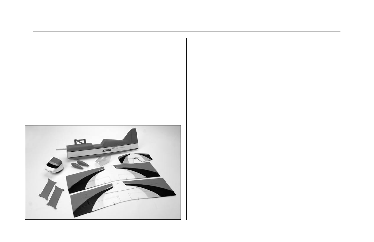
Contents of Kit/Parts Layout
Large Replacement Parts:
EFL2176 Wing Set with Struts
EFL2177 Fuselage with Hatch and Rudder
EFL2178 Horizontal Tail Assembly
EFL2179 Cowl
EFL2180 Wheel Pants
EFL2181 Landing Gear Covers
EFL2182 Hatch
EFL2183 Canopy
EFL2184 Landing Gear
Small Replacement Parts
EFL2007 Hook & Loop, Hinge Tape
EFL2185 Pushrod/Carbon Wing Support Set
EFLA200 Micro Control Horns
EFLA202 Micro Tail Skid
EFLA201 Micro Pushrod Keepers
EFLA203 Micro Control Connectors
EFLA204 Micro Rubber Spinner
EFLA213 E-flite/JR/Horizon Decals
EFLA221 Foam Park Wheels, 1.5"
EFLM207 Pinion Gear, 10T 0.4 Module
EFLM221 Gearbox (v2), 6.6:1, 0.4 Module
EFLM222 Spur Gear, 66T w/Shaft
EFLP1260 12 x 6 Slow Flyer Prop
(Kit includes only 1)
3
Page 4

Required Electronics
High Power Motor Setup*
JRP6654** 6102FM, R610UL & 4-S241—
Complete radio system
JRPR610UL** R610UL 6CH FM Receiver,
Shrink-wrap
EFLRS75 7.5-Gram Sub-Micro Servo (3)
(Includes long servo arms)
or
JRPS241 S241 Sub-micro servo (3)
JRPA212 Long Servo Arms (2)
* Regardless of equipment chosen you will require a
transmitter, micro receiver and three sub-micro servos.
JRPA092 Servo Extension 3"
EFLC3005 Celectra 1- to 3-Cell Li-Po Charger
EFLM1000 Park 370 Brushless Motor, 4100Kv
EFLA311A 20-Amp Brushless ESC (v2)
EFLP1260 12 x 6 Slow Flyer Prop (2)—keep
extras on hand
EFLB1016 11.1V 1200mAh 3-Cell Li-Po,
16GA
or
THP13203S 1320mAh 3-Cell 11.1V Li-Po,
16GA
* Use with included 12 x 6 prop, 6.6:1 gearbox, and 10T
pinion. Proper throttle management is required when using
high performance setups.
4
Page 5

High Power Outrunner (direct drive)
Motor Setup*
EFLM1305 Park 400 Outrunner Motor, 920Kv
EFLA311A 20-Amp Brushless ESC (v2)
EFLM1915 Outrunner Stick Mount
EFLP1047 10 x 4.7 Slow Flyer Prop (2)
or
EFLP1147 11 x 4.7 Slow Flyer Prop (2)
or
APC11038SF 11x3.8 Slow Flyer Propeller
EFLB1016 11.1V 1200mAh 3-Cell Li-Po,
16GA
or
THP13203S 1320mAh 3-Cell 11.1V Li-Po,
16GA
* Proper throttle management is required when using highperformance setups.
Lightweight Setup
EFLM1305 Park 400 Brushless Motor, 920Kv
EFLA311A 20-Amp Brushless ESC (v2)
EFLM1915 Outrunner Stick Mount
EFLP1047 10x4.7 Slow Flyer Propeller (2)
or
APC11038SF 11x3.8 Slow Flyer Propeller
EFLB1005 11.1V 860mAh 3-Cell Li-Po, 16GA
THP9003S 900mAh 3-Cell 11.1V Li-Po, 16GA
Optional Accessories
EFLA110 Power Meter
EFLA212 Gear Puller: 1mm–5mm Shaft
JRPS281 DS281 Micro Digital Servo (3)
5
Page 6

Additional Tools and Adhesives
Tools & Equipment
Hot glue gun (low temperature)
Hobby Knife
Square
Ruler
Felt-tipped pen
T-pins
Paper towel / tissue
150–180 grit sandpaper
Wax paper
String
Tape (blue low tack painters)
Needle-nose pliers
Small Phillips screwdriver
(EFLA257 or included with EFLA250)
Hex Wrench: 3/32" (EFLA251 or included with EFLA250)
Nut Driver: 5.5mm (EFLA255 or included with EFLA250)
EFLA250 Park Flyer Tool Assortment, 5-piece
Adhesives
EFLA208 Foam Safe CA / Activator
Hot glue
Canopy glue
Thread lock (for mounting motor to gearbox)
Important Information about Motor
Selection
We are recommending the E-flite™ Park 370 Brushless
Motor with 4100Kv (EFLM1000) or the Park 400 Outrunner
Brushless Motor, 920Kv (EFLM1305). The Park 370 Brushless
Motor, 4100 Kv provides plenty of power for sport and 3D
pilots with the ability to hover and climb vertically using the
included 6.6:1 gearbox and 12x6 propeller. It is extremely
important to monitor gearbox wear and motor temperature
when using the 4100Kv motor. Lack of proper throttle
management using this motor may result in damage to the
motor, gearbox, ESC, and battery. Proper motor cooling is
very important so make sure the motor is cooled properly in
the cowl. A direct drive Outrunner alternative would be the
Park 400 Outrunner, 920Kv that will also provide plenty of
power without worrying about gearboxes.
Using the Manual
This manual is divided into sections to help make assembly
easier to understand, and to provide breaks between each
major section.
Remember to take your time and follow the directions.
6
Page 7

Warning
Before Starting Assembly
An RC aircraft is not a toy! If misused, it can cause serious
bodily harm and damage to property. Fly only in open
areas, preferably at AMA (Academy of Model Aeronautics)
approved flying sites, following all instructions included with
your radio.
Lithium Polymer batteries are significantly more volatile
than alkaline or Ni-Cd/Ni-MH batteries used in RC
applications. All manufacturer’s instructions and warnings
must be followed closely. Mishandling of Li-Po batteries
can result in fire.
Before beginning the assembly of your Ultimate FX 3D,
remove each part from its bag for inspection. Closely inspect
the fuselage, wing panels, rudder and stabilizer for damage.
If you find any damaged or missing parts, contact the place
of purchase.
7
Page 8

Warranty Information
Horizon Hobby, Inc. guarantees this kit to be free from
defects in both material and workmanship at the date of
purchase. This warranty does not cover any component parts
damage by use or modification. In no case shall Horizon
Hobby’s liability exceed the original cost of the purchased
kit. Further, Horizon Hobby reserves the right to change or
modify this warranty without notice.
In that Horizon Hobby has no control over the final assembly
or material used for the final assembly, no liability shall be
assumed nor accepted for any damage resulting from the
use of the final assembled product. By the act of using the
assembled product, the user accepts all resulting liability.
Please note that once assembly of the model has been
started, you must contact Horizon Hobby, Inc. directly
regarding any warranty question. Please do not contact
your local hobby shop regarding warranty issues, even if
that is where you purchased it. This will enable Horizon to
better answer your questions and service you in the event
that you may need any assistance.
If the buyer is not prepared to accept the liability associated
with the use of this product, the buyer is advised to return
this kit immediately in new and unused condition to the place
of purchase.
Horizon Hobby, Inc.
4105 Fieldstone Road
Champaign, Illinois 61822
877-504-0233
horizonhobby.com
8
Page 9
Wing Installation
Required Parts
Fuselage
Wing (Top and Bottom)
Wing strut (2) 24" (60cm) string
Carbon wing brace,
Carbon wing brace,
Required Tools and Adhesives
Square
Hot glue
Paper towel / tissue
Foam compatible CA
Foam compatible activator
Note: When using a hot glue gun, be sure not
to touch the tip to the foam. The hot tip will
burn and melt the foam.
3
11
/
" (300mm) (2)
4
3
11
/
" (290mm) (2)
8
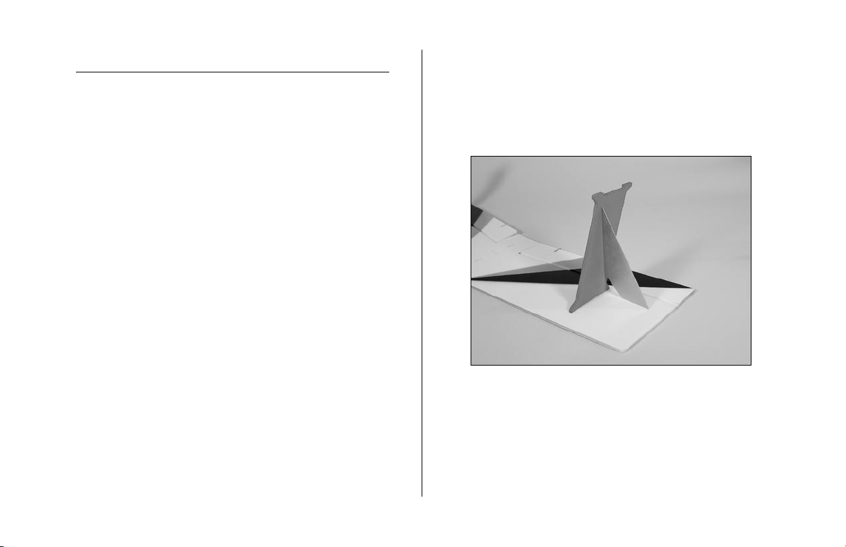
1. Locate the wing struts. Place the struts onto the top
wing, which has the cutouts for the center cabane strut.
The struts angle towards the trailing edge of the wing.
Use a square and either foam compatible CA or hot
glue to secure the struts to the wing.
9
Page 10

2. Attach the bottom wing to the struts using foam
compatible CA or hot glue. Again, check that the
struts are square to the wing.
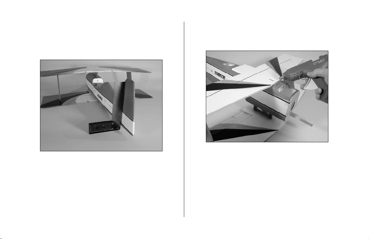
3. Slide the fuselage between the wing panels. Key the
cabane into the top wing. Use foam compatible CA or
hot glue to secure the top wing to the cabane.
10
Page 11
4. Rest the bottom wing flat on the work surface. Use
a square to align the fin perpendicular to the work
surface. Mark the location of the fuselage onto the
bottom wing.
5. Use hot glue to attach the bottom wing to the fuselage.
Do not use foam compatible CA for this step. Use the
marks from Step 4 for alignment.
11
Page 12
Note: The long brace (11
3
/
") goes from
4
the top near the cabane to the strut on the
bottom wing.
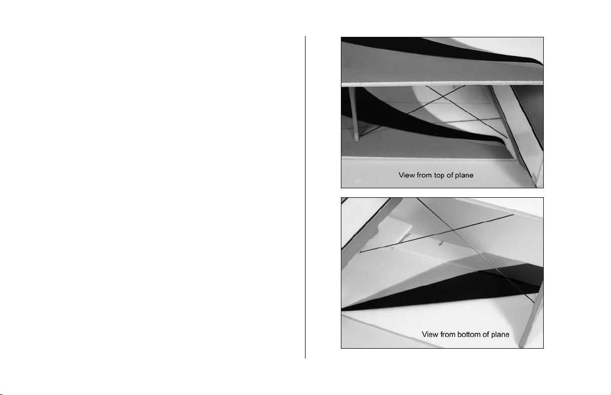
6. Install the carbon wing braces by first positioning a
hole in the bottom of the lower wing by gently sliding
a carbon fiber brace through the four plastic ring
washers at the proper angle, then remove. Next, gently
slide each carbon fiber brace through the plastic ring
washers on the top of the upper wing, at the proper
angle, and have each exit though the plastic ring
washers on the bottom of the lower wing through the
holes you have already made. Glue the braces using
foam compatible CA on the insides and outside the
plastic ring washers to secure them in place.
12
Page 13
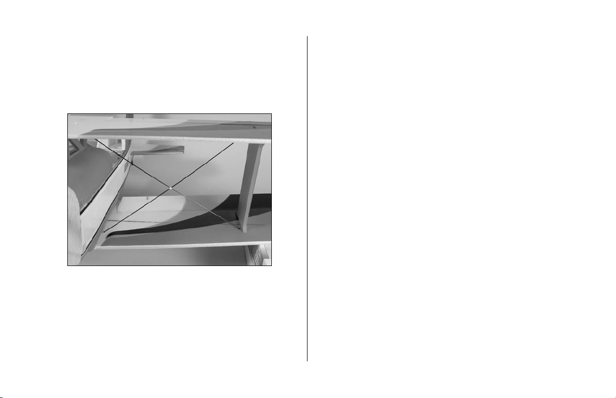
7. Cut the supplied 24" (60cm) string into two equal
12" pieces. Wrap the intersection of the braces with
the string. Make sure to wrap both vertically and
horizontally around the braces. Apply thin CA to the
string to secure its location.
13
Page 14

Horizontal Stab Installation
Required Parts
Stabilizer
Fuselage assembly
110mm x 12mm hinge tape (2)
Required Tools and Adhesives
Ruler
String
T-pins
Tape
Paper towel / tissue
Foam compatible CA
Foam compatible activator
1. Remove the partially taped elevator from the stabilizer.
Slide the stabilizer into the fuselage. Use the supplied
110mm x 12mm clear tape to hinge the elevator half
on the top and bottom of the hinge line.
14
Page 15

2. Use foam compatible CA to attach the elevator joiner
to the elevator. Use low-tack painter’s tape to tape
down the elevator with the joiner attached. Apply
the hot glue to the elevator and then tape down the
remaining elevator half until the glue cures. You may
use activator to speed up the cure time.
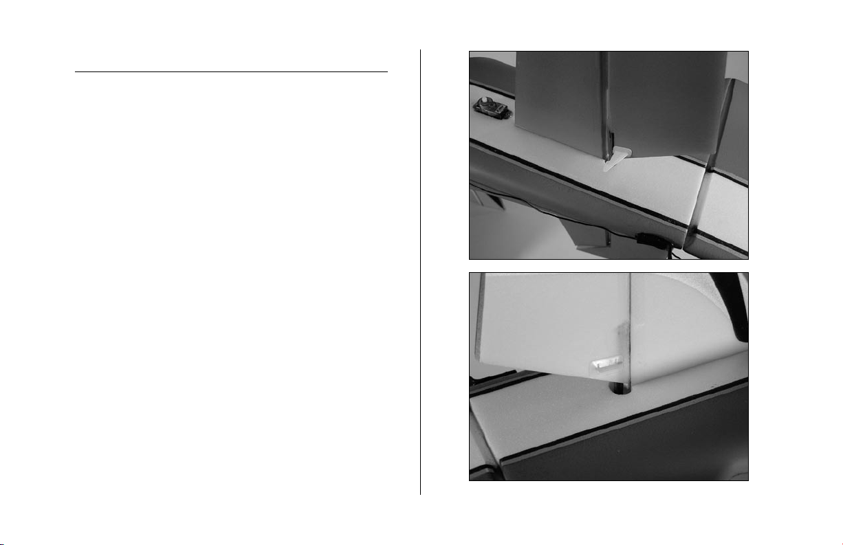
3. Adjust the stabilizer so it is parallel to the wings. It
may be necessary to lightly sand the fuselage where
the stabilizer is inserted to achieve alignment.
15
Page 16

4. Measure from the tips of the stabilizer to the wing tips.
Adjust the stabilizer so both measurements are equal.
Center the stabilizer in the fuselage as well.
5. Double-check the positioning of the stabilizer as
described in Steps 3 and 4. Once satisfied with
the position, use foam
stabilizer to the fuselage. Apply foam
activator as needed.
compatible CA to glue the
compatible
16
Page 17

Landing Gear Installation
Required Parts
Airframe Landing gear
Tail skid
Wheel retainer (2) Landing gear fairing (2)
Wheel pant (2) Wheel pant straps (2)
2mm x 6mm sheet metal screw (4)
Required Tools and Adhesives
Hot glue Foam compatible CA
Needle-nose pliers Hobby knife
1
1
/
" wheel (2)
2
1. Glue the tail skid using foam compatible CA
17
Page 18

2. Install the landing gear into position by pressing it into
the landing gear mount.
Note: If the landing gear is loose and you
choose to permanently attach the gear, use
foam compatible CA to glue the plywood
landing gear retainer into the slot.
18
Page 19
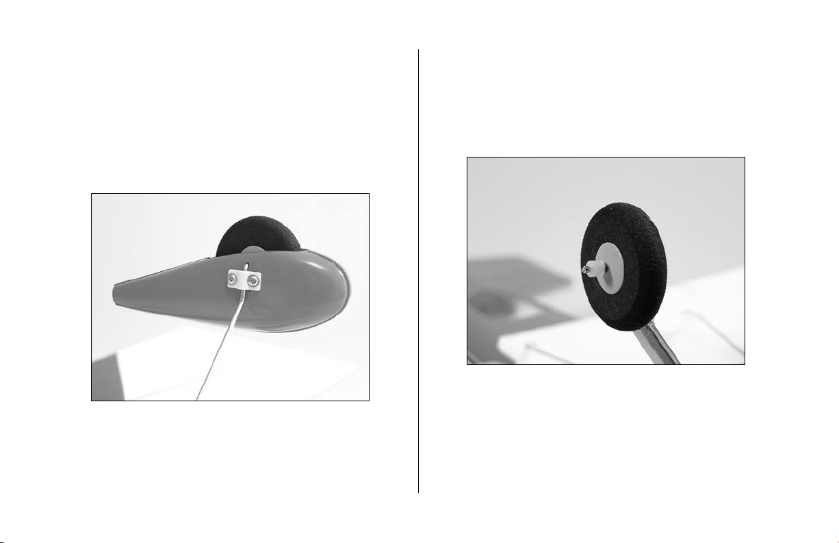
3. Install the wheel pants and wheels. Use needle-nose
pliers to insert the wheel retainers on the ends of each
of the axle portions of the landing gear inside of the
wheel pant. Each wheel pant is secured using two
2mm x 6mm sheet metal screws and a wheel pant
strap. Drill the holes for the screws into the wheel
pants using a hobby knife.
Note: If you choose not to use the wheel pants,
you can secure the wheels on the landing gear
using the wheel retainers. Use hot glue or foam
compatible CA to glue the retainers onto the
end landing gear. Use care not to glue the
wheel to the landing gear.
19
Page 20

4. Attach the landing gear fairing using hot glue. Apply
glue at the top, center and bottom of the fairing only.
You will notice a groove in the fairing that will rest on
the wire.
20
Page 21

Servo & Receiver Installation
Required Parts
Airframe Double-sided tape
Receiver Hook and loop
Servo extension, 3"
Servos: E-flite’s 7.5 gram Sub-Micro (EFLRS75) (3)
Required Tools and Adhesives
Hot glue
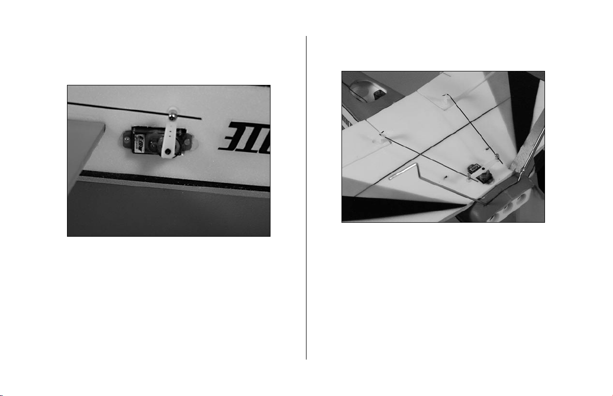
1. Use hot glue to install the rudder, elevator and aileron
servos. A 3" servo extension will be required for the
elevator servo.
21
Page 22

2. Use hook and loop to attach the receiver to the inside
of the fuselage. Route the receiver antenna to the rear
of the fuselage.
Note: Do not cut the receiver antenna.
Changing the length of the antenna will
seriously reduce the range of your radio
system.
22
Page 23
Linkage Installation
Required Parts
Airframe
Long servo arm (3)
Micro control connector (4)
Control connector backplate (4)
2mm x 3mm screw (4)
Micro pushrod keeper (6)
Micro control horn (4)
Micro control horn backplate (4)
Rudder linkage wire, 12" (305mm)
Elevator linkage wire,
Aileron linkage wire,
Aileron inter-connection linkage wire,
Required Tools and Adhesives
Foam compatible CA
Phillips screwdriver (small) Felt-tipped pen
1. Attach the micro control horn to the elevator using
the micro control horn backplates. Apply a few drops
of foam
the control horn.
compatible CA to the backplate where it meets
1
5
/
" (130mm)
8
5
5
/
" (135mm) (2)
16
1
7
/
" (180mm) (2)
8
23
Page 24

2. Install a micro control connector into a long servo
arm. Secure it using the control connector back plates.
Note: Cut off the unused half of the long
3D servo arm for the elevator servo. the aileron
servo will use the complete servo arm.
3. With the radio system on, install the servo arm on
the elevator servo.
24
Page 25

4. Place an “L” bend 1/4" from the end of the
elevator linkage wire, 5
1
/
" (130mm).
8
5. Attach the elevator linkage wire. The “L” bend
side is installed on the elevator control horn using a
micro pushrod keeper. Pass the wire through the micro
control connector.
25
Page 26
6. With the radio system on, hold the elevator in
neutral. Secure the pushrod in the micro control
connector using a 2mm x 3mm screw.
7. Repeat the techniques in Steps 1 through 6 to install
the two aileron linkage wires, 5
5
/
" (135mm).
16
26
Page 27

8. Use low tack painter’s tape to attach the upper
aileron in the neutral position. Attach the “Z” bend
side of the aileron inter-connection linkage wire, 7
(180mm), to the bottom wood aileron horn.
9. Use a felt-tipped pen to mark the wire where it
crosses the hole in the upper aileron horn.
1
/
"
8
27
Page 28
10. Make an “L” bend in the wire and attach “L”
bend side to the upper aileron horn using micro
pushrod keeper.
12. Install a micro control connector into a long servo
arm. Secure it using the control connector back plates.
With the radio system on, install the servo arm on the
rudder servo.
11. Repeat Steps 8 through 10 for the remaining aileron
connecting linkage.
28
Note: You will need to cut the unused half of
the full 3D arm for the rudder servo.
Page 29

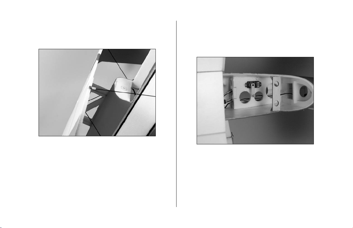
13. Attach the “L” bend side of the 12" (305mm) rudder
linkage wire to the rudder control horn using a micro
pushrod keeper.
14. Slide the wire into the rudder pushrod tube and
pass through the micro control connector on the
rudder servo. Use foam
control horn to the rudder.
compatible CA to attach the
29
Page 30

15. With the radio system on, hold the rudder in neutral.
Secure the pushrod in the micro control connector
using a 2mm x 3mm screw.
30
Page 31

Motor & Speed Control Installation
Required Parts
Airframe
Brushless motor
Brushless speed control
6.6:1 (66T spur) gearbox
2mm x 8mm sheet metal screw
10T pinion gear, 0.4 module x 6mm
Required Tools and Adhesives
Phillips screwdriver (small)
Optional Parts
Outrunner motor
Outrunner Stick Mount (EFLM1915)
Important Information About Your Brushless ESC
Make sure your ESC brake is programmed to off. Also, be
sure to use an ESC with the proper 9V cutoff when using
3-Cell Li-Po packs. We suggest this cutoff to be of the soft
variety to prevent hard motor cutoffs during low-level 3D
flying.
1. It may be necessary to attach motor adapters or other
accessories to your particular motor at this time.
Note: Use the instructions provided with the
motor to install any accessories. Follow the
instructions provided with the gearbox for some
helpful hints for installing the motor. When
installing your motor into the E-flite™ gearbox,
it is very important that the gear mesh is set
correctly and is smooth with no binding. The
E-flite gearbox features adjustable slotted
mounting holes to ensure your gear mesh is
correct. Remember if the gear mesh is too loose
or too tight, it may strip the gears. To extend
the life of your gearbox, we also recommend
using a small amount of grease, such as lithium
grease, on the spur gear.
It is also very important to check to be sure the
propeller is balanced before installing onto the
shaft. An unbalanced propeller may strip the
gears. When installing the propeller, please
be sure not to over-tighten the 3mm locknut.
The use of the locknut will prevent the propeller
from coming loose.
Use the 10-tooth pinion we include with this
airplane on the motor.
31
Page 32

Note: Skip to Page 33 for Outrunner
installation.
2. Attach the motor to the gearbox using the screws
provided with the motor.
3. Slide the gearbox onto the motor shaft. Use a hobby
knife to drill a hole through the plastic and into the
motor mount stick. Secure the gearbox using a
2mm x 8mm sheet metal screw.
Hint: You may want to plug in the speed control
before installing the gearbox.
32
Page 33

Note: When using the E-Flite outrunner motor
and mount, you will need to shorten the motor
mount stick by 13/16" (20mm).
Attach the outrunner motor using the outrunner
stick mount (EFLM1915). Attach mount with
motor to the motor mount stick.
4. Secure the speed control location using hook and
loop. Run the lead from the speed control to the
receiver. It may be necessary to use a servo extension.
Exact speed control location may vary depending on
the brand used and the center of gravity. This photo
shows the location in the front of the fuse if you are
using our E-flite™ 20-amp Brushless ESC.
33
Page 34

Cowling and Canopy Installation
Required Parts
Airframe
Cowling
Canopy
Spinner
2mm x 10mm sheet metal screw (4)
Propeller
(Use 12 x 6 if you are using the provided gearbox with
our recommended motor)
Required Tools and Adhesives
Phillips screwdriver (small)
Nut driver: 5.5mm (for gearbox)
Canopy glue
Hobby knife
1. Slide the cowl onto the fuselage. Center the motor
shaft in the opening.
2. Attach the propeller to the gearbox using the supplied
3mm washer and 3mm locknut. Make sure not to overtighten the 3mm locknut. Install the spinner into position
on the gearbox shaft. If using an Outrunner motor,
install the propeller adapter and propeller.
Note: It is very important that you check to be
sure the propeller is balanced before installing
onto the shaft. An unbalanced propeller may
strip the gear. When installing the propeller,
please do not over-tighten the 3mm locknut. The
use of the locknut will prevent the propeller from
falling off in flight.
34
Page 35
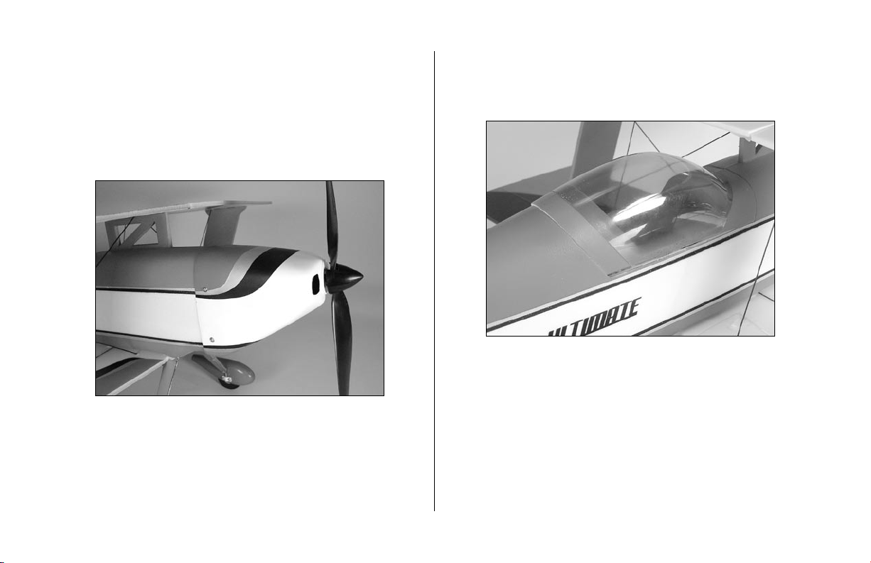
3. Check to make sure the propeller and spinner will
not interfere with the front of the cowl and there is
adequate clearance. Use a hobby knife to make holes
in the cowl at the same location as the tabs on the
fuselage. Secure the cowl to the fuselage using the
2mm x 10mm wood screws and a Phillips screwdriver.
4. Use canopy glue to glue the canopy to the canopy
hatch. Once the glue has cured, place the hatch into
position.
35
Page 36
Center of Gravity / Battery Installation
Required Parts
Airframe
Battery
Hook and loop
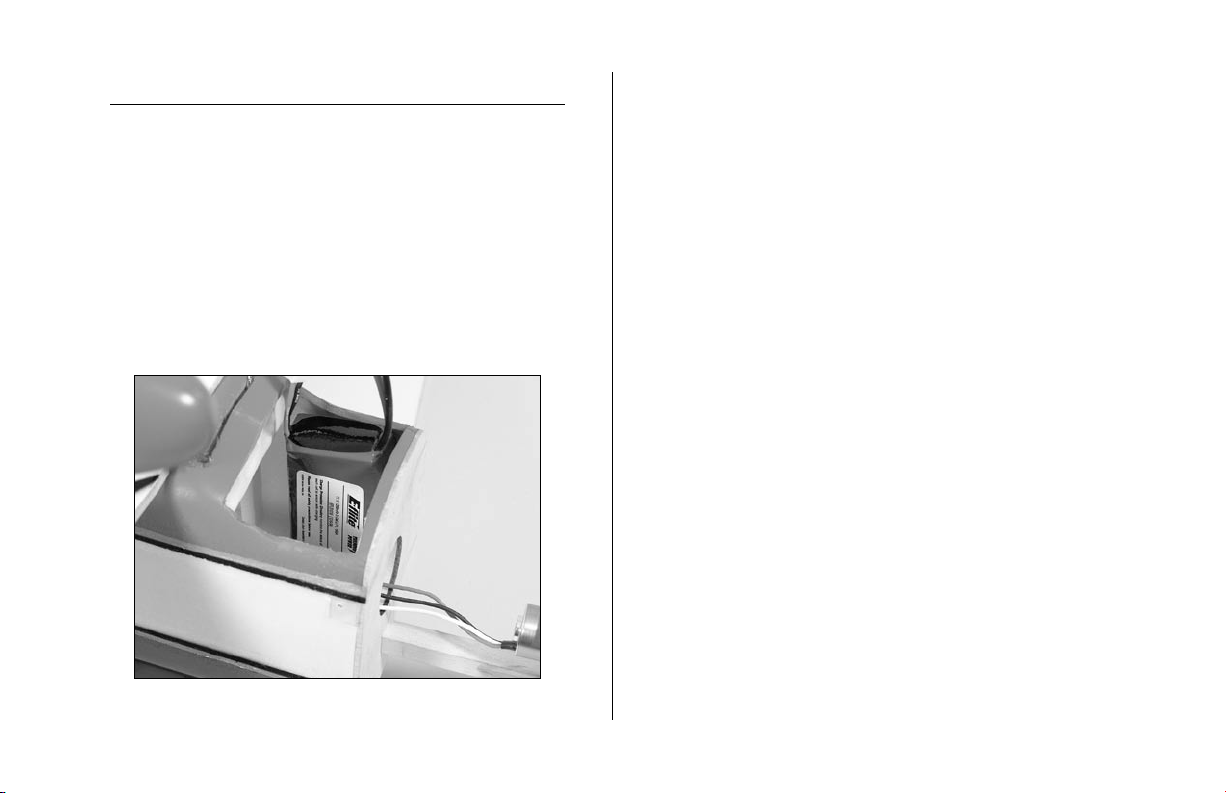
1. The battery for the Ultimate FX is located inside
the front of the fuselage behind the firewall. The
battery attaches to the side of the fuselage with
hook and loop material.
An important part of preparing the aircraft for flight is
properly balancing the model.
Caution: Do not inadvertently skip this step!
The recommended Center of Gravity (CG) location for the
Ultimate FX is 3
1
/
" (90mm) to 4" (100mm) behind the
2
leading edge of the upper wing against the fuselage.
The C.G. range was determined from our flight tests using a
Thunder Power 11.1V 1320mAh Li-Po battery pack.
36
Page 37

Control Throws
1. Turn on the transmitter and receiver of your Ultimate
FX. Check the movement of the rudder using the
transmitter. When the stick is moved right, the rudder
should also move right. Reverse the direction of the
servo at the transmitter if necessary.
2. Check the movement of the elevator with the radio
system. Moving the elevator stick down will make the
airplane elevator move up.
3. Use a ruler to adjust the throw of the elevator, ailerons
and rudder. Adjust the position of the pushrod at the
control horn to achieve the following measurements
when moving the sticks to their endpoints.
Ailerons:
Low Rate 1" (25mm) or 20 degrees Up/Down
High Rate 1
1
/
" (38mm) or 30 degrees Up/Down
2
Elevator:
Low Rate 1" (25mm) or 25 degrees Up/Down
High Rate 2
3
/
" (60mm) or 45 degrees Up/Down
8
Rudder:
Low Rate 1" (25mm) or 20 degrees Right/Left
High Rate 1
5
/
" (40mm) or 30 degrees Right/Left
8
These are general guidelines measured from our own flight
tests. You can experiment with higher rates and exponentials
to match your preferred style of 3D flying.
37
Page 38

2005 Official AMA
National Model Aircraft Safety Code
GENERAL
1) I will not fly my model aircraft in sanctioned events,
air shows or model flying demonstrations until it
has been proven to be airworthy by having been
previously, successfully flight tested.
2) I will not fly my model higher than approximately
400 feet within 3 miles of an airport without notifying
the airport operator. I will give right-of-way and avoid
flying in the proximity of full-scale aircraft. Where
necessary, an observer shall be utilized to supervise
flying to avoid having models fly in the proximity of
full-scale aircraft.
3) Where established, I will abide by the safety rules
for the flying site I use, and I will not willfully or
deliberately fly my models in a careless, reckless and/
or dangerous manner.
4) The maximum takeoff weight of a model is 55
pounds, except models flown under Experimental
Aircraft rules.
5) I will not fly my model unless it is identified with
my name and address or AMA number on or in the
model. (This does not apply to models while being
flown indoors.)
6) I will not operate models with metal-bladed
propellers or with gaseous boosts, in which gases
other than air enter their internal combustion
engine(s); nor will I operate models with extremely
hazardous fuels such as those containing
tetranitromethane or hydrazine.
RADIO CONTROL
1) I will have completed a successful radio equipment
ground range check before the first flight of a new or
repaired model.
2) I will not fly my model aircraft in the presence
of spectators until I become a qualified flier, unless
assisted by an experienced helper.
38
Page 39

3) At all flying sites a straight or curved line(s) must
be established in front of which all flying takes place
with the other side for spectators. Only personnel
involved with flying the aircraft are allowed at or in
front of the flight line. Intentional flying behind the
flight line is prohibited.
4) I will operate my model using only radio control
frequencies currently allowed by the Federal
Communications Commission. (Only properly licensed
Amateurs are authorized to operate equipment on
Amateur Band frequencies.)
5) Flying sites separated by three miles or more
are considered safe from site-to site interference,
even when both sites use the same frequencies. Any
circumstances under three miles separation require a
frequency management arrangement, which may be
either an allocation of specific frequencies for each site
or testing to determine that freedom from interference
exists. Allocation plans or interference test reports
shall be signed by the parties involved and provided
to AMA Headquarters. Documents of agreement and
reports may exist between (1) two or more AMA
Chartered Clubs, (2) AMA clubs and individual AMA
members not associated with AMA Clubs, or (3) two or
more individual AMA members.
6) For Combat, distance between combat engagement
line and spectator line will be 500 feet per cubic inch
of engine displacement. (Example: .40 engine = 200
feet.); electric motors will be based on equivalent
combustion engine size. Additional safety requirements
will be per the RC Combat section of the current
Competition Regulations.
7) At air shows or model flying demonstrations, a
single straight line must be established, one side of
which is for flying, with the other side for spectators.
8) With the exception of events flown under AMA
Competition rules, after launch, except for pilots or
helpers being used, no powered model may be flown
closer than 25 feet to any person.
9) Under no circumstances may a pilot or other person
touch a powered model in flight.
39
Page 40

7906
© 2005 Horizon Hobby, Inc.
4105 Fieldstone Road
Champaign, Illinois 61822
(877) 504-0233
horizonhobby.com
e-fliterc.com
 Loading...