

Page 1
Stearman PT-17 15e ARF
Assembly Manual
Specifications
Wingspan 44 in (1117mm)
Length 35 in (889mm)
Wing Area 608 sq in (37.5 sq dm)
Weight with Battery 3.5–3.8 lb (1.5–1.7 kg)
Weight without Battery 3.1–3.3 lb (1.4–1.5 kg)
Pilots not included (available separately)
Page 2

Table of Contents
Product Registration......................................................2
Introduction ...............................................................2
Warranty Information................................................. 2
Using the Manual...................................................... 2
Contents of Kit/Parts Layout........................................ 2
Recommended Radio Equipment...................................3
Recommended Equipment.............................................3
Optional Accessories....................................................3
Required Tools and Adhesives.......................................3
Warning.....................................................................3
Note on Lithium Polymer Batteries..................................3
Rudder and Elevator Servo Installation............................4
Stabilizer and Fin Installation.........................................5
Rudder and Elevator Pushrod Installation........................8
Landing Gear Installation............................................11
Cabane Strut and Center Section Installation.................11
Aileron Installation.....................................................15
Aileron Linkage Installation.........................................16
Motor and ESC Installation..........................................17
Cowling Installation....................................................18
Interplane and Wing Transport Jig Installation...............19
Battery Installation......................................................22
Receiver Installation....................................................23
Wing Installation........................................................24
Center of Gravity........................................................25
Control Throws...........................................................26
Preflight.....................................................................26
Safety, Precautions and Warnings...............................27
Age Requirements......................................................27
Safety Do’s and Don’ts for Pilots...................................27
Warranty Information.................................................28
2009 Official Academy of Model
Aeronatics Safety Code........................................30
Instructions for Disposal of WEEE by
Users in the European Union................................31
Product Registration
Registering your product will provide you the option
to stay up-to-date on product information, new
products, customization options and other information
for E-flite owners. Register your product today at
www.E-fliteRC.com/register.
Introduction
The Stearman PT-17 was a primary flight trainer used by
the U.S. Army Air Corps (USAAC) during World War II.
The PT-17 was a conventional biplane design with an
open, two-place cockpit to accommodate a student and
instructor, in tandem. The aircraft was constructed with
wood wings and a welded steel fuselage, all covered
with fabric. The plane became highly recognizable with
its biplane design and exposed radial engine. The
PT-17 was known as a rugged aircraft and an excellent
trainer. The PT-17 was designed by the Stearman
Aircraft Corporation and in 1934 Boeing purchased the
company. Boeing manufactured over 10,500 PT-17s and
when production ended it became known as the last
production military biplane built in the United States.
Important Warranty Information
Please read our Warranty and Liability Limitations
section on page 25 before building this product. If you
as the Purchaser or user are not prepared to accept the
liability associated with the use of this Product, you are
advised to return this Product immediately in new and
unused condition to the place of purchase.
Using the Manual
This manual is divided into sections to help make
assembly easier to understand, and to provide breaks
between each major section. In addition, check boxes
have been placed next to each step to keep track
of its completion. Steps with a single circle (Ο) are
performed once, while steps with two circles (Ο Ο)
indicate that the step will require repeating, such as for
a right or left wing panel, two servos, etc.
Remember to take your time and follow the directions.
Contents of Kit/Parts Layout
Replacement Parts
EFL2951T Top Outboard Wing Set
EFL2951C Center Top Wing
EFL2951B Bottom Wing Set
EFL2952 Fuselage with Hatch
EFL2953 Tail Set
EFL2954 Cowling with Dummy Motor
EFL2955 Wing Tube Set
EFL2956 N Wing Strut Set
EFL2957 Cabane Strut Set
EFL2958 Main Landing Gear Set
EFL2959 Tail Wheel Set
EFL2960 Windscreen Set
EFL2961 Pushrod Set
EFL2962 Wing Transport Jigs
EFL2963 Hatch
EFL2964 Hardware Pack
2
2
E-flite Stearman PT-17 15e ARF Assembly Manual
Page 3
Recommended Radio Equipment
Recommended Equipment
Warning
You will need a minimum of a 4-channel transmitter,
receiver and four servos. You can choose to purchase a
complete radio system, or if you are using an existing
transmitter, just purchase the other required equipment
separately. We recommend the crystal-free, interferencefree Spektrum™ DX5e 2.4GHz DSM® 5-channel system.
If using your own transmitter, we recommend the JR
SPORT MN48 and MC35 servos.
If you own a Spektrum radio, just add a DSM2™
receiver, two JR SPORT MN48, and two JR SPORT
MC35 servos. We show the installation of the AR500
receiver in this manual.
Radio System
SPM5500 DX5e DSM2 5CH system
Or Purchase Separately
any of the Following Receiver
SPMAR500 AR500 DSM2 5-Channel Full-Range
Receiver (for DX5e, DX6i, or DX7)
SPMAR6200 AR6200 DSM2 6-Channel Full Range
Receiver (for DX5e, DX6i, or DX7)
s
And
JSP20040 MN48 Mini Servo (2)
JSP20030 MC35 Micro Servo (2)
JRPA096 9-inch Servo Extension (2)
EFLM4015A Power 15 Brushless Outrunner 950Kv
EFLA1040 40A Pro Brushless ESC
EFLB32003S 3200mAh 3S 11.1V 20C Li-Po
APC12060E Electric Propeller 12 x 6E
Optional Accessories
EFLA110 Power Meter
EFLC3005 Celectra™ 1- to 3-Cell Li-Po Charger
EFLC505 Intelligent 1- to 5-Cell Balancing
Charger
EFLA150 Military Pilot (1 or 2)
Required Tools and Adhesives
Tools & Equipment
Manila card stock Pliers
Low-tack tape Pencil
Pin vise Clear tape
Ruler Hook and loop tape
T-pins Philips screwdriver: #0, #1
Felt-tipped pen Hobby knife (#11 blade)
Mixing sticks Toothpicks
1/16-inch drill bit Sidecutters
Rubbing alcohol Paper towels
Double-sided tape Cable tie
Stick-on lead weight Square
Mixing cups
Allen wrench or balldriver: 3/32-inch, 7/64-inch
Adhesives
Thin CA Medium CA
Threadlock 6-minute epoxy (HAN8000)
An RC aircraft is not a toy! If misused, it can cause
serious bodily harm and damage to property. Fly only in
open areas, preferably at AMA (Academy of Model
Aeronautics) approved flying sites, following all
instructions included with your radio. Keep loose items
that can get entangled away from the propeller,
including loose clothing, or other objects such as pencils
and screwdrivers. Especially keep your hands away from
the propeller.
During the course of building your PT-17
ARF we suggest that you use a soft surface
for the building surface. A foam stand, large
piece of bedding foam or a thick bath towel
will work well and help protect the model
from damage during assembly.
Note on Lithium Polymer Batteries
Lithium Polymer batteries are
significantly more volatile than
alkaline or Ni-Cd/Ni-MH
batteries used in RC applications.
All manufacturer’s instructions and
warnings must be followed closely.
Mishandling of Li-Po batteries can
result in fire. Always follow the
manufacturer’s instructions when
disposing of Lithium Polymer
batteries.
E-flite Stearman PT-17 15e ARF Assembly Manual
3
3
Page 4
Rudder and Elevator Servo Installation
Parts Required
Fuselage assembly Mini servos with hardware (2)
Radio system JR MatchMaker
Tools Required
Pin vise 1/16-inch drill bit
Sidecutters Thin CA
Felt-tipped pen Philips screwdriver #0
Ο 1. Remove the cockpit hatch by lifting at the rear then
pulling aft to disengage the tabs at the forward
end. Set the hatch aside.
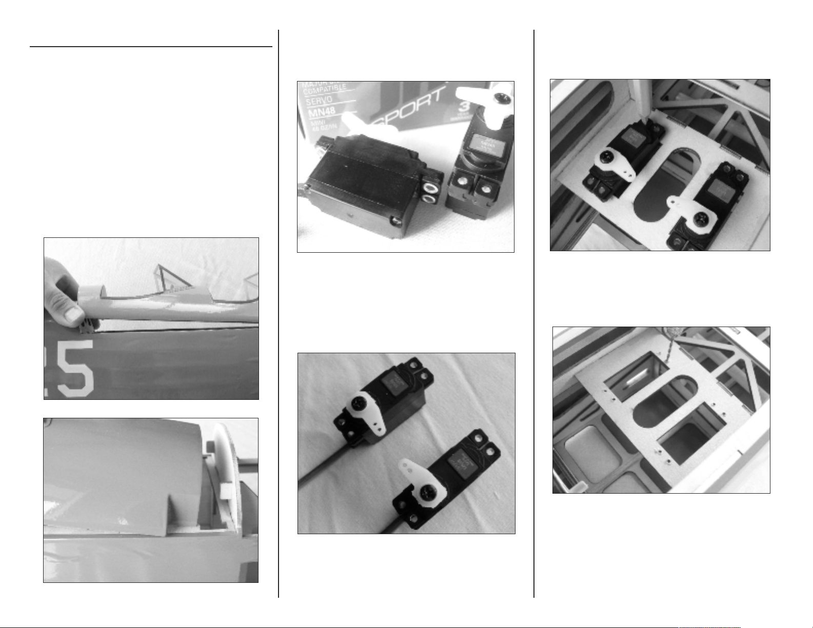
Ο 2. Install the grommets and bushings in the rudder
and elevator servos. Note that the bushing is
installed from the bottom of the mounting lugs.
Ο 4. Place the rudder and elevator servos in the
fuselage servo cutouts and mark the mounting
holes with a felt-tipped pen.
Ο 3. Center the servos using your radio or a JR
MatchMaker. Using sidecutters, remove three of
the arms from each standard servo horn,
leaving one long arm on each as shown.
Ο 5. Remove the servos. Use a 1/16-inch drill bit
in a pin vise to drill the mounting holes.
4
4
E-flite Stearman PT-17 15e ARF Assembly Manual
Page 5
Ο 6. Apply 2-3 drops of thin CA to each mounting
screw hole to strengthen the wood. This will
make the servo mounting screws more secure
when installed.
Ο 7. Using a #0 Philips screwdriver and the screws
provided with the servos, install the rudder and
elevator servos in the fuselage with the arms
inboard and towards the rear of the fuselage.
Stabilizer and Fin Installation
Parts Required
Fuselage Stabilizer
Elevator Rudder
CA hinges (8) Tailwheel assembly
Tools Required
Felt-tipped pen Thin CA Ruler
Allen wrench Square Threadlock
Rubbing alcohol Paper towels T-pins
6-minute epoxy Toothpicks Mixing sticks
Mixing cups Hobby knife (#11 blade)
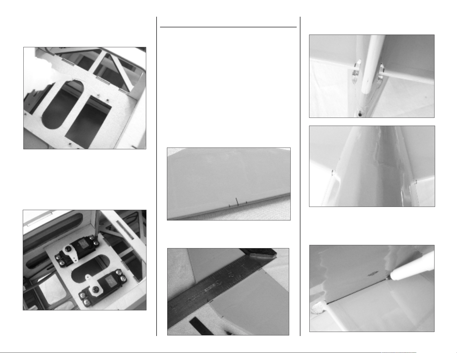
Ο 1. Use a ruler to mark the center of the trailing edge
of the stabilizer. Measure 13/32-inch each side of
center and make a mark using a felt-tip pen.
Ο 3. Slide the stabilizer into the fuselage and align the
marks made with the fuselage sides.
E-flite Stearman PT-17 15e ARF Assembly Manual
Ο 2. Use a square to transfer the centerline to the
leading edge, then make a mark 1-1/8-inches
each side of the center.
Ο 4. Use a felt-tipped pen to mark the bottom of the
stabilizer along the fuselage sides.
5
5
Page 6
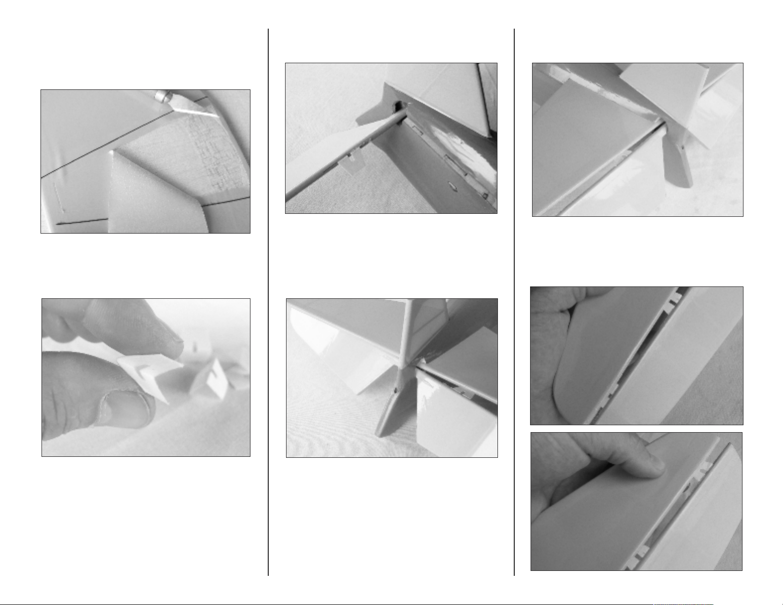
Ο 5. Remove the stabilizer and use a hobby knife with
#11 blade to remove a section of covering
approximately 1/4-inch inside the marked lines,
and the leading and trailing edges.
Ο 7. Slide the elevator into the fuselage and insert the
six hinges.
Ο 9. Then install the left inboard hinge by angling the
elevator the opposite direction.
Ο 6. Prepare six elevator hinges by folding them in
half to form a crease.
Ο 8. Slide the stabilizer into the fuselage. First install the
right side inboard hinge, by angling the elevator
as shown.
Ο 10. Next, insert the left and right center and outboard
hinges in the stabilizer.
6
6
E-flite Stearman PT-17 15e ARF Assembly Manual
Page 7
Ο 11. Align the elevator with the stabilizer and apply
2 - 3 drops of thin CA to each hinge. Do not use
accelerator on the hinges as the CA needs to
penetrate the hinge for a complete bond.
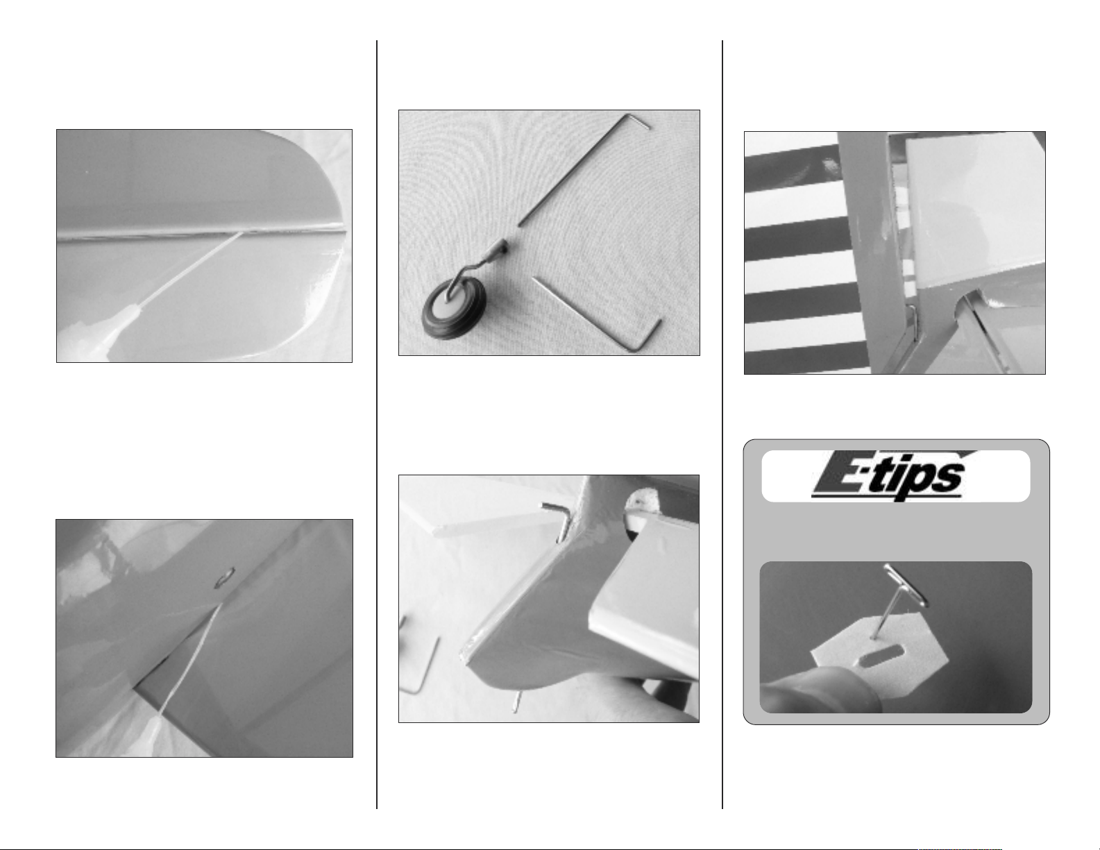
Ο 13. Locate the tailwheel assembly. Using the supplied
Allen wrench, separate the tailwheel shaft from the
wheel assembly.
Ο 15. Install two hinges in the rudder. Mix a small
amount of 6-minute epoxy and apply it to the tail
wheel shaft hole in the rudder with a toothpick,
then slide the rudder assembly on to the fin.
Use rubbing alcohol to clean any excess epoxy.
Ο 12. Using the marks made in steps 1, 2 and 4, check
that the stabilizer is aligned with the fuselage.
Apply several drops of thin CA to each side of the
joint to glue the stabilizer in place.
E-flite Stearman PT-17 15e ARF Assembly Manual
Ο 14. Install the tailwheel shaft in the fuselage.
Use a T-pin in the center of each hinge to ensure
that it remains centered during installation.
7
7
Page 8
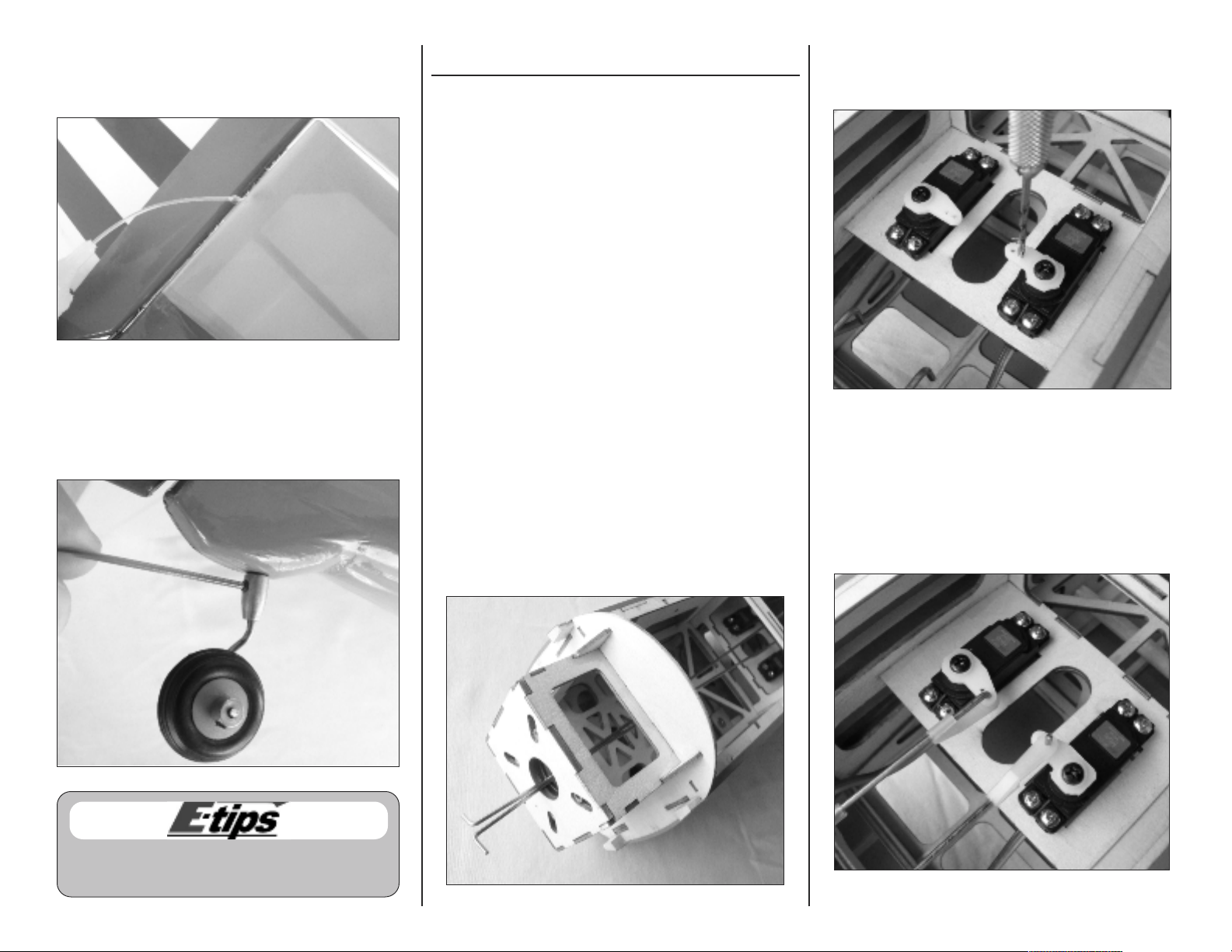
Ο 16. Apply a few drops of thin CA to each rudder
hinge. Do not use accelerator on the hinges so the
CA can penetrate the hinges completely.
Ο 17. Install the tailwheel using the supplied 1.5mm
Allen wrench. Apply a small amount of threadlock
to the setscrew before installation to prevent it from
vibrating loose.
Rudder and Elevator Pushrod Installation
Parts Required
Fuselage assembly
Elevator pushrod wire, 16-1/2-inch (419mm)
Rudder pushrod wire, 17-3/4-inch (451mm)
Nylon control horn backplate (2)
2mm x 10mm machine screw (4)
Nylon control horn (2) Nylon clevis (2)
Nylon pushrod keeper (2) Silicone keeper (2)
Tools Required
Pin vise 1/16-inch drill bit
Pliers Ruler
Felt-tipped pen Thin CA
Philips screwdriver #0 Sidecutters
Ο 1. Locate the rudder and elevator pushrods. The
longer pushrod is for the rudder and installed on
the left hand side. The shorter pushrod is installed
on the right hand side for the elevator.
Insert the pushrods in the guide tubes by feeding
them into the fuselage through the opening in the
center of the firewall.
Ο 2. Use a 1/16-inch drill bit in a pin vise to enlarge
the outer hole in the rudder servo arm and the
inner hole in the elevator servo arm.
Ο 3. Fit the pushrods to the servo arms and secure with
the pushrod keepers. Note that the elevator
pushrod is installed inverted so that the bend in the
wire does not contact the servo case.
Use threadlock on all metal-to-metal fasteners to
keep them from vibrating loose.
8
8
E-flite Stearman PT-17 15e ARF Assembly Manual
Page 9
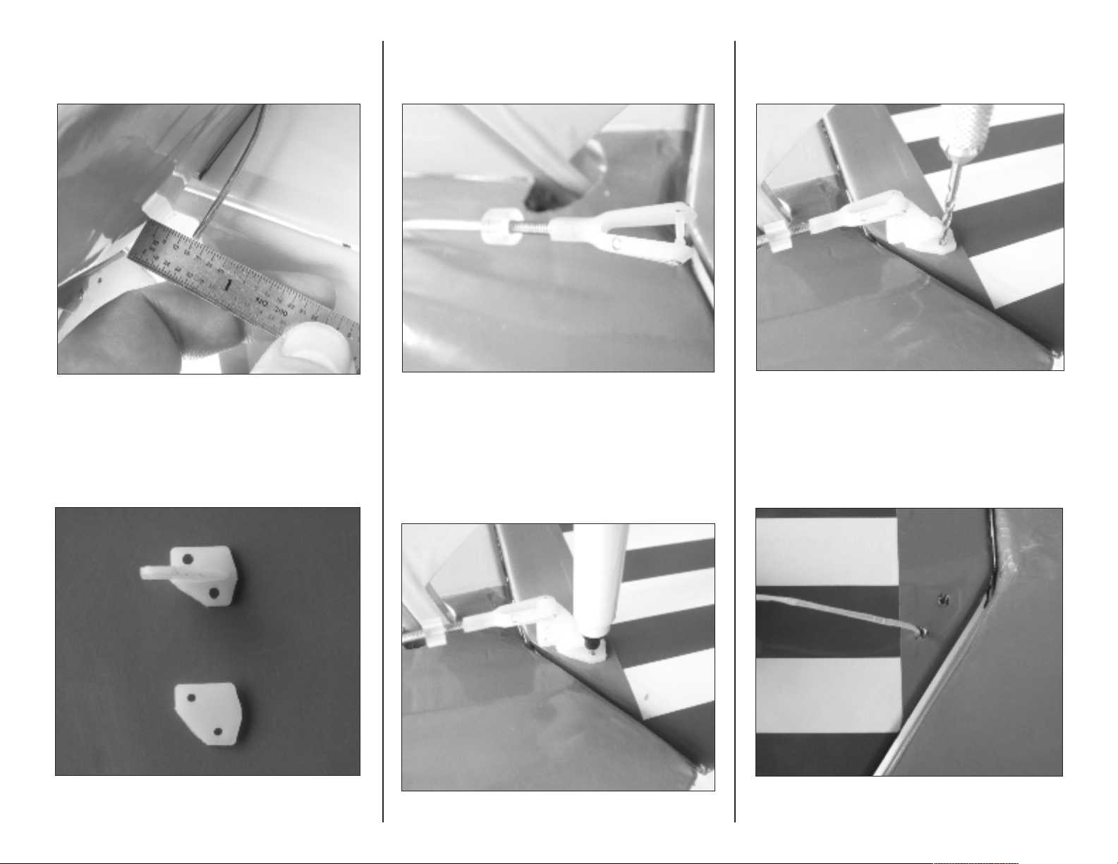
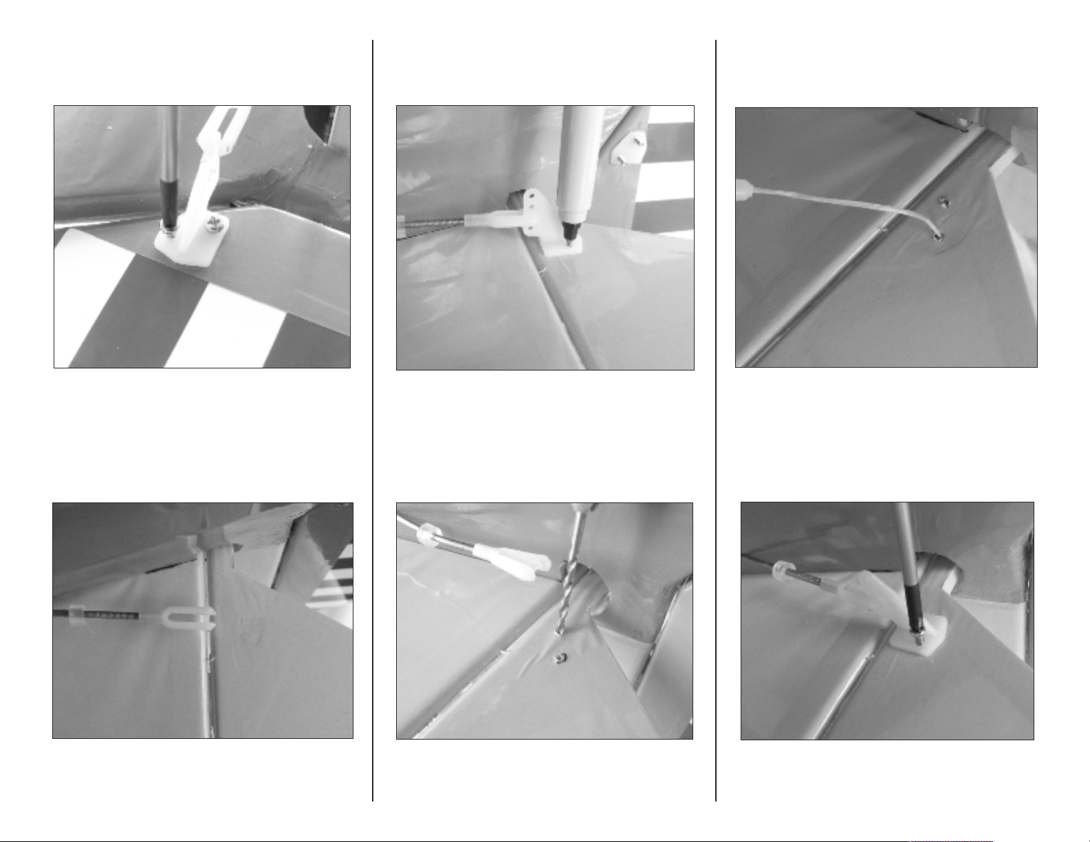
Ο 4. Use a pair of pliers to place a bend in the rudder
pushrod so that the threaded end is 1/2-inch from
the fuselage side.
Ο 6. Install a silicone keeper and clevis on the rudder
pushrod so that the clevis pin is aligned with the
rudder hinge line.
Ο 8. Use the marks and the control horn as reference to
drill the mounting holes with a pin vise and 1/16inch drill bit.
Ο 5. Use a pair of sidecutters to prepare a control horn
for the rudder by cutting off one corner.
E-flite Stearman PT-17 15e ARF Assembly Manual
Ο 7. Connect the clevis to the control horn. Hold the
control horn in position against the rudder and
mark the screw locations with a felt-tipped pen.
Ο 9. Apply 1 - 2 drops of thin CA to each screw hole to
strengthen the wood and stop it from crushing.
9
9
Page 10
Ο 10. Install the rudder control horn and backing plate
with two 2mm x 10mm machine screws using a
#0 Philips screwdriver.
Ο 12. Connect a control horn to the clevis at the second
hole from the bottom and mark the screw holes on
the elevator with a felt-tipped pen.
Ο 14. Apply 1 - 2 drops of thin CA to each screw hole
to strengthen the wood and stop it crushing
when the horn is installed.
Ο 11. Place a silicone keeper on the elevator pushrod,
then thread on a clevis until the clevis pin is
aligned with the elevator hinge line.
110
0
Ο 13. Use a 1/16-inch drill bit in a pin vise to make the
holes for the control horn screws.
Ο 15. Install the elevator control horn and backing plate
with two 2mm x 10mm machine screws using a
#0 Philips screwdriver.
E-flite Stearman PT-17 15e ARF Assembly Manual
Page 11

Landing Gear Installation
Parts Required
Landing gear (left and right)
Fuselage assembly
6-32 x 3/8-inch Allen bolts (4)
#6 washers (4)
ΟΟ 2. Using a 7/64-inch balldriver, secure the
landing gear with two 6-32 x 3/8-inch Allen
bolts and #6 washers. Use threadlock on the
bolts to prevent them from vibrating loose.
Cabane Strut and Center Section Installation
Parts Required
Cabane struts (4) Fuselage assembly
Wing center section #4 steel washers (4)
4-40 x 1/4-inch Allen bolts (8)
4-40 x 3/8-inch Allen bolts (4)
Tools Required
7/64-inch balldriver or Allen wrench
Threadlock
ΟΟ 1. With the fuselage inverted, insert the landing
gear into the fuselage until the mounting holes
align with the holes in the fuselage.
Tools Required
3/32-inch balldriver or Allen wrench
Threadlock
Ο 1. Use a 3/32-inch balldriver to install each of the
four cabane struts to the fuselage with 4-40 x
1/4-inch Allen bolts. Apply a small amount of
threadlock to each bolt to prevent them from
vibrating loose.
Ο 3. Repeat steps 1 and 2 for the opposite side.
E-flite Stearman PT-17 15e ARF Assembly Manual
Note:
All cabane struts are the same.
Use threadlock on all metal-to-metal fasteners to
keep them from vibrating loose.
111
1
Page 12

Ο 2. Place the wing center section inverted on the work
surface. Lower the fuselage onto the center section
and align the upper ends of the cabane struts with
the mounting locations. Use a 3/32-inch balldriver
to install the four 4-40 x 3/8-inch Allen bolts and
#4 washers. Apply a small amount of threadlock to
the bolts to prevent them from vibrating loose.
Aileron Servo Installation
Parts Required
Lower wing panels (L and R)
Micro servos with hardware (2)
2mm x 10mm sheet metal screws (8)
Servo mounting blocks (4) Control horns (2)
Radio system JR MatchMaker
Tools Required
Philips screwdriver #0 6-minute epoxy
Mixing cups Mixing sticks
Paper towels Rubbing alcohol
Thin CA Medium CA
Pencil Sidecutters
Pin vise 1/16-inch drill bit
Low-tack tape
Ο 1. Prepare the aileron servos by installing the
rubber grommets and bushings.
Ο 2. Use a #0 screwdriver to remove the small arms
from the servos. Using sidecutters, remove three
arms from a larger servo arm, leaving one long
arm. Center the servos using your radio system or
JR MatchMaker and install an arm on each servo,
one opposite to the other.
ΟΟ 3. Remove the aileron hatch from the wing.
112
2
E-flite Stearman PT-17 15e ARF Assembly Manual
Page 13

ΟΟ 4. Hold the servo in place on the underside of the
hatch with the arm centered in the opening and
aligned with the edge of the hatch.
ΟΟ 6. Use medium CA or 6-minute epoxy to glue the
servo mounting blocks to the aileron hatch.
ΟΟ 8. Use a 1/16-inch drill bit in a pin vise to make
the servo mounting holes.
ΟΟ 5. Use a pencil to mark the location of the servo
mounting tabs.
E-flite Stearman PT-17 15e ARF Assembly Manual
ΟΟ 7. Place the servo on the hatch and use a pencil to
mark the servo mounting holes.
ΟΟ 9. Apply 2-3 drops of thin CA to each hole to
strengthen the wood.
113
3
Page 14

ΟΟ 10. Using a #0 Philips screwdriver, install the
aileron servo to the hatch with the screws
provided with the servo.
ΟΟ 11. Use a 1/16-inch drill bit in a pin vise to
enlarge the outer hole in the servo arm.
ΟΟ 12. Remove the tape from the string near the
aileron servo opening in the wing. Tape or tie
the string to the aileron servo lead. and use it
to pull the lead through the wing.
ΟΟ 13. Use the string to pull the aileron servo lead
through the wing.
ΟΟ 14. Apply 1-2 drops of thin CA to each of the
aileron hatch mounting holes in the wing.
ΟΟ 15. Using a #0 Philips screwdriver, attach the
aileron servo and hatch to the wing with four
2mm x 10mm sheet metal screws.
114
Ο 16. Repeat steps 3 through 15 for the opposite wing.
4
E-flite Stearman PT-17 15e ARF Assembly Manual
Page 15

Aileron Installation
Parts Required
Lower wing panels w/ailerons (L & R)
CA hinges (6)
Tools Required
Thin CA Felt-tipped pen
ΟΟ 1. Prepare three CA hinges by inserting a T-pin in
the center of each hinge.
ΟΟ 2. Remove the tape holding the aileron to the wing
and separate the aileron. Insert a hinge into
each of the hinge slots in the leading edge of
the aileron.
ΟΟ 3. Slide the aileron hinges into the hinge slots in
the trailing edge of the lower wing panel.
ΟΟ 4. Slide the aileron and wing panel together on
the hinges then remove the T-pins.
ΟΟ 5. Align the trailing edge of the aileron with the
trailing edge of the wing. Slide the aileron left
or right as necessary to maintain an even gap
at each end of the aileron.
E-flite Stearman PT-17 15e ARF Assembly Manual
115
5
Page 16

ΟΟ 6. Apply a few drops of thin CA to each of the
three aileron hinges. Do not use accelerator as
the CA needs to penetrate the hinges fully for a
complete bond.
Ο 7. Repeat steps 1 through 6 for the opposite lower
wing panel.
Aileron Linkage Installation
Parts Required
Lower wing panels w/ailerons (L & R)
Aileron wire pushrods, 1-5/8-inch (41mm) (2)
2mm x 10mm sheet metal screws (4)
Nylon control horn (2) Nylon clevis (2)
Silicone keeper (2)
Tools Required
1/16-inch drill bit Pin Vise
Felt-tipped pen Low-tack tape
Philips screwdriver #0
ΟΟ 1. Install a silicone keeper and nylon clevis on to a
1-5/8-inch (41mm) aileron pushrod.
ΟΟ 2. Insert the pushrod into the outer hole in the
servo arm and adjust the clevis so that the clevis
pin is aligned with the aileron hinge line.
ΟΟ 3. Attach a control horn to the clevis and mark the
mounting hole locations with a felt-tipped pen.
116
6
E-flite Stearman PT-17 15e ARF Assembly Manual
Page 17

ΟΟ 4. Use a 1/16-inch drill bit in a pin vise to drill the
control horn mounting holes. Use care not to
drill all the way through the aileron.
ΟΟ 5. Apply 2–3 drops of thin CA to each hole to
strengthen the wood and prevent the screws
vibrating loose.
ΟΟ 6. Use a #0 Philips screwdriver to install the control
horn to the aileron with 2mm x 10mm sheet
metal screws.
Motor and ESC Installation
Parts Required
Motor with mounting hardware Fuselage assembly
1/2-inch (13mm) spacers ESC
4-40 x 1 inch Allen bolts (4) #4 washers (4)
Cable tie (not included) Hook and loop tape
Tools Required
Philips screwdriver #1 3/32-inch balldriver
Threadlock
Ο 1. Use hook and loop tape to attach the ESC
to the lower side of the motor box.
Use a low-tack tape ‘flag’ on the drill bit to prevent
drilling all the way through the aileron. For the
PT-17 a depth of 3/8-inch works well.
E-flite Stearman PT-17 15e ARF Assembly Manual
Ο 7. Repeat steps 1 to 6 for the oppposite wing panel.
117
7
Page 18

Ο 2. Using a #1 Philips screwdriver, install the motor
mount using the screws supplied with the motor.
Use threadlock on the screws to prevent them
loosening due to vibration.
Ο 3. Using a 3/32-inch balldriver, install the motor and
1/2-inch (13mm) spacers on the firewall with four
4-40 x 1 inch Allen bolts and #4 washers. Use
threadlock on the bolts to prevent them loosening
due to vibration. The motor wires should exit
towards the bottom of the fuselage.
Ο 4. Connect the three motor wires to the ESC wires.
Ο 5. Use a cable tie to organize the motor and ESC
wires on the left side of the firewall.
Cowling Installation
Parts Required
Fuselage assembly Cowling
2mm x 10mm sheet metal screws (4)
Cockpit hatch
Tools required
Pin vise 1/16-inch drill bit
Manila card stock Felt-tipped pen
Low-tack masking tape Thin CA
Philips screwdriver #0 Punch or awl
Ο 1. Replace the cockpit hatch on the fuselage. Use a
felt-tipped pen to mark the center of each of the
four cowl mounting blocks.
118
8
E-flite Stearman PT-17 15e ARF Assembly Manual
Page 19

Ο 2. Use a 1/16-inch drill bit in a pin vise to drill a
hole in the center of each cowl mounting block.
Ο 3. Prepare four 2” x 1/2-inch alignment tabs from
manila card stock. At the end of each tab use a
punch or an awl to form a hole.
Ο 4. Use low-tack masking tape to tape the alignment
tabs to the fuselage with their holes centered over
the holes in the cowl mounting blocks.
Ο 5. Install the cowling on the fuselage, making sure
that the alignment tabs are on the outside of the
cowl. Use the cowl opening as an alignment guide
by centering it on the motor.
Ο 6. Verify that the motor can rotate without contacting
the cowling, then secure the cowling to the fuselage
with low-tack tape.
Ο 7. Use a felt-tipped pen to mark the mounting hole
locations on the cowling.
E-flite Stearman PT-17 15e ARF Assembly Manual
119
9
Page 20

Ο 8. Remove the cowling. Use a 1/16-inch drill bit in a
pin vise to drill the mounting holes at the marked
locations on the cowling.
Ο 9. Use a #0 Philips screwdriver to attach the cowling
to the fuselage with four 2mm x 10mm sheet
metal screws.
Ο 10. Remove the cowling and apply 1-2 drops of thin
CA to each of the mounting holes.
We recommend that this be done after the
cowl has been mounted and the screws have
formed a thread in the blocks. This will prevent
them from splitting.
Interplane Strut and Transport Jig Installation
Parts Required
Upper and lower wing panels (L & R)
Upper carbon wing tube, 14-3/8-inch (365mm)
Lower carbon wing tube, 10-5/8-inch (270mm)
4-40 x 1/4-inch Allen bolts (8)
4-40 x 3/8-inch Allen bolts (4)
Fuselage assembly Interplane struts (2)
Wing transport jigs Rubber bands (4)
#4 washers (12)
Tools Required
3/32-inch balldriver Threadlock
Ο 1. Install the upper and lower wing joiner tubes in the
center section and fuselage. The upper tube is 143/8-inches (365mm) long. The lower is 10- 5/8inches (70mm).
220
0
E-flite Stearman PT-17 15e ARF Assembly Manual
Page 21

Ο 2. With the fuselage inverted, slide the lower wing
panels on to the joiner tube and install the 4-40 x
3/8-inch retaining boltsand #4 washers witha
3/32-inch balldriver.
Ο 4. The interplane struts are installed so that they form
an ‘N’ when viewed fom the right side of the
model. The upper strut ends have squared off ends.
The lower ends are angled.
Ο 5. Using a 3/32-inch balldriver, install the interplane
struts to the outboard side of the mounthing lugs in
the wing panels with 4-40 x 1/4-inch Allen bolts
and #4 washers. Use threadlock on the bolts to
prevent them from loosening due to vibration.
Ο 3. Repeat for the upper wing panels.
E-flite Stearman PT-17 15e ARF Assembly Manual
Use threadlock on all metal-to-metal fasteners to
keep them from vibrating loose.
Ο 6. A set of wing transport jigs is provided so that the
left and right wing assemblies can be transported
and installed as complete units.
221
1
Page 22

ΟΟ 7. Insert the transport jig between the wing
panels approximately 1/2-inch outboard of the
upper panel separation point.
ΟΟ 9. Use a 3/32-inch balldriver to remove the wing
retaining screws and remove the wing panel
assembly from the fuselage.
Battery Installation
Parts Required
Fuselage assembly Battery strap
Hook and loop tape
Ο 1. Remove the cockpit hatch. Install a battery strap
around the battery tray in preparation for later
mounting of the battery.
ΟΟ 8. Secure the panels to the transport jig using a
rubber band on the upper and lower panel.
222
2
Ο 10. Repeat Steps 7, 8, and 9 to remove the opposite
wing panels.
Ο 2. Attach a piece of adhesive backed hook
and loop tape to the battery and tray to help
locate the battery and stop it moving in flight.
E-flite Stearman PT-17 15e ARF Assembly Manual
Page 23

Receiver Installation
Parts Required
Fuselage assembly
9-inch servo extension lead (2)
Receiver
Tools Required
Clear tape Hook and loop tape
Double-sided adhesive tape
Ο 1. Attach the receiver to the right hand side of the
battery compartment with double sided adhesive
tape. Connect the throttle lead from the ESC.
ΟΟ 2. Feed a 9-inch long servo extension lead from
the aileron lead opening in the lower wing root
to the receiver.
ΟΟ 3. Repeat for the opposite side and connect the
leads to the receiver.
Ο 4. Connect the rudder and elevator servo leads to
the receiver.
Ο 5. Secure the long antenna to the front of the radio
tray with clear tape.
E-flite Stearman PT-17 15e ARF Assembly Manual
223
3
Page 24

Wing Installation
Parts Required
Fuselage assembly
Wing panels on transport jigs (L & R)
Upper carbon wing tube, 14-3/8-inch (365mm)
Lower carbon wing tube, 10-5/8-inch (270mm)
4-40 x 3/8-inch Allen bolts (4)
#4 washers (12)
Tools Required
3/32-inch balldriver
Ο 1. Install the upper and lower carbon wing tubes in
the wing center section and fuselage.
Ο 2. Slide the left and right wing panel assemblies
approximately half-way on to the wing tubes,
leaving about a 1-1/2-inch gap between the wing
and fuselage/center section.
Ο 4. Slide the wing assemblies completely on to the
wing tubes while feeding the aileron servo leads
into the fuselage.
Ο 5. Use a 3/32-inch balldriver to secure the wing
panels with one 4-40 x 3/8-inch Allen bolt and
#4 washer per wing panel.
224
Ο 3. Connect the aileron servo lead to the extension
lead coming out of the fuselage.
Ο 6. Remove the rubber bands and transport jigs
before flight.
4
E-flite Stearman PT-17 15e ARF Assembly Manual
Page 25

Center of Gravity
An important part of preparing the aircraft for flight is
properly balancing the model.
Caution: Do not inadvertently skip this step!
The recommended balance point for the PT-17 is
3-1/4 to 3-3/4 inches (82 to 95mm) behind the
leading edge of the upper wing. Mark the range for
the Center of Gravity on the underside of the upper
wing as shown. Interplane strut removed for clarity.
It will be necessary to assemble the model to a
flight ready state in order to check the center of
gravity location.
Parts Required
Assembled model Propeller
Motor battery
Tools Required
Felt-tipped pen Ruler
Stick-on lead weight
Ο 1. Install the motor battery.
Ο 3. Use a commercial balancing device or suspend
the model on fingertips within the recommended
center of gravity range to check the balance.
Ο 4. Due to the short nose moment of the Stearman
PT-17, between 2 to 4 ounces of nose weight will
be required. Determine the amount by temporarily
placing it on the dummy engine at the cylinder
location. When the appropriate amount is known,
remove the cowling and attach the weight inside at
the base of the dummy engine cylinders. Form a
curve in the weight prior to installation so that it
conforms to the interior of the cowling and does
not interfere with operation of the motor.
E-flite Stearman PT-17 15e ARF Assembly Manual
Ο 2. Install the propeller adapter and propeller. The
shaft of a screwdriver or Allen wrench can be used
to tighten the propeller nut.
225
5
Page 26

Control Throws
Ο 1. Turn on your transmitter, plug in the motor battery
and switch on the receiver power. Make any clevis
adjustments necessary to center the control
surfaces, then secure all the clevises with the
silicone keepers.
Ο 2. Check the movement of the rudder using the
transmitter. When the stick is moved right, the
rudder should also move right.
Ο 3. Check the movement of the elevator with the
radio system. Moving the elevator stick toward the
bottom of the transmitter will make the elevator
move up.
Ο 4. Check the movement of the ailerons with the
radio system. Moving the aileron stick right will
make the right aileron move up and the left aileron
move down.
Ο 5. Reverse the direction of the servos at the transmitter
as necessary.
Ο 6. Use a ruler to adjust the throw of the elevator,
ailerons and rudder. Adjust the travel volume or
dual rate in your transmitter to achieve the
following measurements when moving the sticks to
their endpoints.
Aileron
Up 3/4-inch (19mm)
Down 3/4-inch (19mm)
Elevator
Up 1/2-inch (13mm)
Down 1/2-inch (13mm)
Rudder
Left 1-1/2-inch (38mm)
Right 1-1/2-inch (38mm)
These are general guidelines measured from our
own flight tests. You can experiment with higher
rates to match your preferred style of flying.
Due to the lifting nature of the flat-bottomed airfoil,
your PT-17 may require a few clicks of down trim
for level flight, especially at higher power settings.
Preflight
Check Your Radio
Before going to the field, be sure that your batteries
are fully charged per the instructions included with
your radio. Charge both the transmitter and receiver
pack for your airplane. Use the recommended charger
supplied with your particular radio system, following
the instructions provided with the radio. In most cases,
the radio should be charged the night before going
out flying.
Before each flying session, be sure to range check your
radio. See your radio manual for the recommended
range and instructions for your radio system. Each
radio manufacturer specifies different procedures for
their radio systems. Next, start the motor. With the
model securely anchored, check the range again.
The range test should not be significantly affected. If
it is, don’t attempt to fly! Have your radio equipment
checked out by the manufacturer.
Double-check that all controls (aileron, elevator, rudder
and throttle) move in the correct direction.
Check the radio installation and make sure all the
control surfaces are moving correctly (i.e. the correct
direction and with the recommended throws). Test run
the motor and make sure it transitions smoothly from
off to full throttle and back. Also ensure the engine is
installed according to the manufacturer’s instructions,
and it will operate consistently.
226
Measurements are taken at the widest
point on the control surface.
Travel Adjust, Sub Trim and Dual Rates are
not listed and should be adjusted according
to each individual model and preference.
6
Check all the control horns, servo horns, and
clevises to make sure they are secure and in good
condition. Replace any items that would be considered
questionable. Failure of any of these components in
flight could mean the loss of your aircraft.
E-flite Stearman PT-17 15e ARF Assembly Manual
Page 27

Flying Your Stearman PT-17 ARF
Safety, Precautions and Warnings
Age Requirements
Flying the Stearman PT-17 ARF is a bunch of fun and
will be enjoyable for all skill levels.
A very light wing loading and mild control throws make
for some enjoyable evening flying. Verify that your CG is
at the correct location as per the manual and that you
have your rates set up to your liking. Verify all control
throws are in the correct direction and the motor spins in
the correct direction also.
Point the model into the wind and add some throttle trim
until the motor begins to turn. This will be your flight idle.
Now, apply power slowly, the model may swing slightly
to the left so some right rudder may be needed on takeoff. You will find the model will become airborne very
quickly and at a low speed. This model excels at flying
slow and easy. Trim the model for level flight at half
throttle. In most cases the PT-17 will require a few degrees of down trim. The Stearman PT-17 ARF has plenty
of power with the E-flite Power 15 so you will only need
to use full throttle for maneuvering.
To land the Stearman PT-17 ARF, just reduce the throttle
to idle and feed in up elevator until the model settles into
a slightly nose-high attitude. Gently fly the model down
to the landing spot with a final flair at touchdown. You
will find the model will have a very short roll out. Both
wheel landings and 3 point landings are capable with
this aircraft. We hope you enjoy the Stearman PT-17
ARF as much as we do.
As the user of this product, you are solely responsible
for operating it in a manner that does not endanger
yourself and others or result in damage to the product
or the property of others.
• Always operate your model in an open area away
from cars, traffic or people.
• Avoid operating your model in the street where
injury or damage can occur.
• Never operate the model out into the street or
populated areas for any reason.
• Never operate your model with low transmitter
batteries.
• Carefully follow the directions and warnings for
this and any optional support equipment (chargers,
rechargeable battery packs, etc.) that you use.
• Keep all chemicals, small parts and anything
electrical out of the reach of children.
• Moisture causes damage to electronics. Avoid water
exposure to all equipment not specifically designed
and protected for this purpose.
Age Recommendation: 14 years or over. This is not
a toy. This product is not intended for use by children
without direct adult supervision.
Safety Do’s and Don’ts for Pilots
• Check all control surfaces prior to each takeoff.
• Do not fly your model near spectators, parking
areas or any other area that could result in injury
to people or damage of property.
• Do not fly during adverse weather conditions.
Poor visibility can cause disorientation and loss of
control of your aircraft. Strong winds can cause
similar problems.
• Do not take chances. If at any time during flight
you observe any erratic or abnormal operation,
land immediately and do not resume flight until the
cause of the problem has been ascertained and
corrected. Safety can never be taken lightly.
• Do not fly near power lines.
Happy landings.
E-flite Stearman PT-17 15e ARF Assembly Manual
227
7
Page 28

Warranty Information
DAMAGE LIMITS
QUESTIONS, ASSISTANCE , AND REPAIRS
WARRANTY PERIOD
Exclusive Warranty- Horizon Hobby, Inc., (Horizon)
warranties that the Products purchased (the "Product")
will be free from defects in materials and workmanship
at the date of purchase by the Purchaser.
LIMITED WARRANTY
(a) This warranty is limited to the original Purchaser
("Purchaser") and is not transferable. REPAIR OR
REPLACEMENT AS PROVIDED UNDER THIS
WARRANTY IS THE EXCLUSIVE REMEDY OF THE
PURCHASER. This warranty covers only those Products
purchased from an authorized Horizon dealer. Third
party transactions are not covered by this warranty.
Proof of purchase is required for warranty claims.
Further, Horizon reserves the right to change or modify
this warranty without notice and disclaims all other
warranties, express or implied.
(b) Limitations- HORIZON MAKES NO WARRANTY OR
REPRESENTATION, EXPRESS OR IMPLIED, ABOUT
NON-INFRINGEMENT, MERCHANTABILITY OR
FITNESS FOR A PARTICULAR PURPOSE OF THE
PRODUCT. THE PURCHASER ACKNOWLEDGES THAT
THEY ALONE HAVE DETERMINED THAT THE PRODUCT
WILL SUITABLY MEET THEREQUIREMENTS OF THE
PURCHASER’S INTENDED USE.
(c) Purchaser Remedy- Horizon's sole obligation
hereunder shall be that Horizon will, at its option, (i)
repair or (ii) replace, any Product determined by Horizon
to be defective. In the event of a defect, these are the
Purchaser's exclusive remedies. Horizon reserves the right
to inspect any and all equipment involved in a warranty
claim. Repair or replacement decisions are at the sole
discretion of Horizon. This warranty does not cover
cosmetic damage or damage due to acts of God,
accident, misuse, abuse, negligence, commercial use, or
modification of or to any part of the Product. This
warranty does not cover damage due to improper
installation, operation, maintenance, or attempted repair
by anyone other than Horizon. Return of any goods by
Purchaser must be approved in writing by Horizon
before shipment.
HORIZON SHALL NOT BE LIABLE FOR SPECIAL,
INDIRECT OR CONSEQUENTIAL DAMAGES, LOSS OF
PROFITS OR PRODUCTION OR COMMERCIAL LOSS IN
ANY WAY CONNECTED WITH THE PRODUCT,
WHETHER SUCH CLAIM IS BASED IN CONTRACT,
WARRANTY, NEGLIGENCE, OR STRICT LIABILITY.
Further, in no event shall the liability of Horizon exceed
the individual price of the Product on which liability is
asserted. As Horizon has no control over use, setup, final
assembly, modification or misuse, no liability shall be
assumed nor accepted for any resulting damage or
injury. By the act of use, setup or assembly, the user
accepts all resulting liability.If you as the Purchaser or
user are not prepared to accept the liability associated
with the use of this Product, you are advised to return this
Product immediately in new and unused condition to the
place of purchase.Law: These Terms are governed by
Illinois law (without regard to conflict of law principals).
SAFETY PRECAUTIONS
This is a sophisticated hobby Product and not a toy. It
must be operated with caution and common sense and
requires some basic mechanical ability. Failure to
operate this Product in a safe and responsible manner
could result in injury or damage to the Product or other
property. This Product is not intended for use by children
without direct adult supervision. The Product manual
contains instructions for safety, operation and
maintenance. It is essential to read and follow all the
instructions and warnings in the manual, prior to
assembly, setup or use, in order to operate correctly and
avoid damage or injury.
Your local hobby store and/or place of purchase cannot
provide warranty support or repair. Once assembly,
setup or use of the Product has been started, you must
contact Horizon directly. This will enable Horizon to
better answer your questions and service you in the
event that you may need any assistance. For questions or
assistance, please direct your email to
productsupport@horizonhobby.com, or call
877.504.0233 toll free to speak to a service technician.
INSPECTION OR REPAIRS
If this Product needs to be inspected or repaired, please
call for a Return Merchandise Authorization (RMA). Pack
the Product securely using a shipping carton. Please note
that original boxes may be included, but are not
designed to withstand the rigors of shipping without
additional protection. Ship via a carrier that provides
tracking and insurance for lost or damaged parcels, as
Horizon is not responsible for merchandise until it arrives
and is accepted at our facility. A Service Repair Request
is available at www.horizonhobby.com on the “Support”
tab. If you do not have internet access, please include a
letter with your complete name, street address, email
address and phone number where you can be reached
during business days, your RMA number, a list of the
included items, method of payment for any non-warranty
expenses and a brief summary of the problem. Your
original sales receipt must also be included for warranty
consideration. Be sure your name, address, and RMA
number are clearly written on the outside of the shipping
carton.
228
8
E-flite Stearman PT-17 15e ARF Assembly Manual
Page 29

WARRANTY INSPECTION AND REPAIRS
To receive warranty service, you must include your
original sales receipt verifying the proof-of-purchase
date. Provided warranty conditions have been met, your
Product will be repaired or replaced free of charge.
Repair or replacement decisions are at the sole
discretion of Horizon Hobby.
NON-WARRANTY REPAIRS
Should your repair not be covered by warranty the
repair will be completed and payment will be required
without notification or estimate of the expense unless the
expense exceeds 50% of the retail purchase cost. By
submitting the item for repair you are agreeing to
payment of the repair without notification. Repair
estimates are available upon request. You must include
this request with your repair. Non-warranty repair
estimates will be billed a minimum of ½ hour of labor. In
addition you will be billed for return freight. Please
advise us of your preferred method of payment. Horizon
accepts money orders and cashiers checks, as well as
Visa, MasterCard, American Express, and Discover
cards. If you choose to pay by credit card, please
include your credit card number and expiration date.
Any repair left unpaid or unclaimed after 90 days will
be considered abandoned and will be disposed of
accordingly. Please note: non-warranty repair is only
available on electronics and model engines.
UUnniitteedd SSttaatteess::
Electronics and engines requiring inspection or repair
should be shipped to the following address:
Horizon Service Center
4105 Fieldstone Road
Champaign, Illinois 61822
All other Products requiring warranty inspection or
repair should be shipped to the following address:
Horizon Product Support
4105 Fieldstone Road
Champaign, Illinois 61822
Please call 877-504-0233 or e-mail us at
productsupport@horizonhobby.com with any questions
or concerns regarding this product or warranty.
UUnniitteedd KKiinnggddoomm::
Electronics and engines requiring inspection or repair
should be shipped to the following address:
Horizon Hobby UK
Units 1-4 Ployters Rd
Staple Tye
Harlow, Essex
CM18 7NS
United Kingdom
Please call +44 (0) 1279 641 097 or e-mail us at
sales@horizonhobby.co.uk with any questions or
concerns regarding this product or warranty.
Germany:
Electronics and engines requiring inspection or repair
should be shipped to the following address:
Horizon Technischer Service
Hamburger Strasse 10
25335 Elmshorn
Germany
Please call +49 4121 46199 66 or e-mail us at
service@horizonhobby.de with any questions or concerns
regarding this product or warranty.
E-flite Stearman PT-17 15e ARF Assembly Manual
229
9
Page 30

2009 Official Academy of Model
Aeronautics Safety Code
GENERAL
1. A model aircraft shall be defined as a non-human
carrying device capable of sustained flight in the
atmosphere. It shall not exceed limitations established in
this code and is intended to be used exclusively for
recreational or competition activity.
2. The maximum takeoff weight of a model aircraft,
including fuel, is 55 pounds, except for those flown
under the AMA Experimental Aircraft Rules.
3. I will abide by this Safety Code and all rules
established for the flying site I use. I will not willfully
fly my model aircraft in a reckless and/or
dangerous manner.
4. I will not fly my model aircraft in sanctioned events,
air shows, or model demonstrations until it has
been proven airworthy.
5. I will not fly my model aircraft higher than
approximately 400 feet above ground level, when within
three (3) miles of an airport without notifying the airport
operator. I will yield the rightof-way and avoid flying in
the proximity of fullscale aircraft, utilizing a spotter when
appropriate.
6. I will not fly my model aircraft unless it is identified
with my name and address, or AMA number, inside or
affixed to the outside of the model aircraft. This does not
apply to model aircraft flown indoors.
7. I will not operate model aircraft with metal-blade
propellers or with gaseous boosts (other than air), nor
will I operate model aircraft with fuels containing
tetranitromethane or hydrazine.
8. I will not operate model aircraft carrying pyrotechnic
devices which explode burn, or propel a projectile of any
kind. Exceptions include Free Flight fuses or devices that
burn producing smoke and are securely attached to the
model aircraft during flight. Rocket motors up to a Gseries size may be used, provided they remain firmly
attached to the model aircraft during flight. Model
rockets may be flown in accordance with the National
Model Rocketry Safety Code; however ,they may not be
launched from model aircraft.Officially designated
AMAAir Show Teams (AST) are authorized to use
devices and practices as defined within the Air Show
Advisory Committee Document.
9. I will not operate my model aircraft while under
the influence of alcohol or within eight (8) hours of
having consumed alcohol.
10. I will not operate my model aircraft while using
any drug which could adversely affect my ability to
safely control my model aircraft.
11. Children under six (6) years old are only allowed
on a flightline or in a flight area as a pilot or while
under flight instruction.
12. When and where required by rule, helmets must
be properly worn and fastened. They must be
OSHA, DOT, ANSI, SNELL or NOCSAE approved
or comply with comparable standards.
RADIO CONTROL
1. All model flying shall be conducted in a manner to
avoid over flight of unprotected people.
2. I will have completed a successful radio equipment
ground-range check before the first flight of a new
or repaired model aircraft.
3. I will not fly my model aircraft in the presence of
spectators until I become a proficient flier, unless I
am assisted by an experienced pilot.
4. At all flying sites a line must be established, in front of
which all flying takes place. Only personnel associated
with flying the model aircraft are allowed at or in front of
the line. In the case of airshows demonstrations straight
line must be established. An area away from the line
must be maintained for spectators. Intentional flying
behind the line is prohibited.
5. I will operate my model aircraft using only radiocontrol frequencies currently allowed by the Federal
Communications Commission (FCC). Only individuals
properly licensed by the FCC are authorized to operate
equipment on Amateur Band frequencies.
6. I will not knowingly operate my model aircraft within
three (3) miles of any preexisting flying site without a
frequency-management agreement. A frequency
management agreement may be an allocation of
frequencies for each site, a day use agreement between
sites, or testing which determines that no interference
exists. A frequency-management agreement may exist
between two or more AMA chartered clubs, AMA clubs
and individual AMA members, or individual AMA
members. Frequency-management agreements,
including an interference test report if the agreement
indicates no interference exists, will be signed by all
parties and copies provided to AMA Headquarters.
7. With the exception of events flown under official AMA
rules, no powered model may be flown outdoors closer
than 25 feet to any individual, except for the pilot and
located at the flightline.
8. Under no circumstances may a pilot or other person
touch a model aircraft in flight while it is still under
power, except to divert it from striking an individual.
330
0
E-flite Stearman PT-17 15e ARF Assembly Manual
Page 31

9. Radio-controlled night flying is limited to low performance model aircraft (less than 100 mph).
The model aircraft must be equipped with a lighting system which clearly defines the aircraft’s attitude and direction at all times.
10. The operator of a radio-controlled model aircraft
shall control it during the entire flight, maintaining
visual contact without enhancement other than by
corrective lenses that are prescribed for the pilot. No
model aircraft shall be equipped with devices which
allow it to be flown to a selected location which is beyond the visual range of the pilot.
PARK FLYER SAFE OPERATING RECOMMENDATIONS
- Inspect your model before every flight to make
certain it is airworthy.
- Be aware of any other radio frequency user who
may present an interference problem.
- Always be courteous and respectful of other users
of your selected flight area.
- Choose an area clear of obstacles and large
enough to safely accommodate your flying activity.
- Make certain this area is clear of friends and
spectators prior to launching your aircraft.
- Be aware of other activities in the vicinity of your
flight path that could cause potential conflict.
- Carefully plan your flight path prior to launch.
- Abide by any and all established AMA National
Model Aircraft Safety Code.
Instructions for Disposal of WEEE by
Users in the European Union
This product must not be disposed of with other waste.
Instead, it is the user’s responsibility to dispose of their
waste equipment by handing it over to a designated
collection point for the recycling of waste electrical
and electronic equipment. The separate collection
and recycling of your waste equipment at the time
of disposal will help to conserve natural resources
and ensure that it is recycled in a manner that protects
human health and the environment. For more
information about where you can drop off your waste
equipment for recycling, please contact your local city
office, your household waste disposal service or where
you purchased the product.
E-flite Stearman PT-17 15e ARF Assembly Manual
331
1
Page 32

© 2009 Horizon Hobby, Inc.
4105 Fieldstone Road
Champaign, Illinois 61822
USA
(877) 504-0233
horizonhobby.com
E-fliteRC.com
Printed 06/09 15665
 Loading...