

Page 1
Mini ShowTime 4D ARF
Assembly Manual
Specifications
Wingspan: 43 in (1090mm)
Length: 42 in (1065mm)
Wing Area: 414 sq in (26.7 sq dm)
Weight w/o Battery: 23–24 oz (650–680 g)
Weight w/Battery: 26–29 oz (795–820 g)
Radio: 6 channels w/ 4 servos
Page 2

Table of Contents
Introduction
Introduction ..........................................................................2
Using the Manual .................................................................
UltraCote Trim Scheme .........................................................
Contents of Kit/Parts Layout ..................................................
Required Tools and Adhesives ...............................................
Optional Accessories ............................................................
Required Radio Equipment ....................................................
Notes Regarding Servos and ESC .........................................
Important Information About Motor Selection .........................
High Power Outrunner Setup ................................................
Notes on Lithium Polymer Batteries ........................................
Warning ..............................................................................5
Warranty Period ..................................................................
Limited Warranty .................................................................
Damage Limits .....................................................................
Safety Precautions ................................................................
Questions, Assistance, and Repairs .......................................
Inspection or Repairs ............................................................
Warranty Inspection and Repairs ..........................................
Non-Warranty Repairs .........................................................
Safety, Precautions, and Warnings ........................................
Landing Gear Installation ......................................................
Outrunner Motor Installation ...............................................
Cowling Installation ............................................................
Aileron Hinging .................................................................
Aileron Servos and Linkages ...............................................
Wing Installation ................................................................
Stabilizer and Elevator
Rudder and Fin ..................................................................
Rudder and Elevator Servos ................................................
Final Assembly ...................................................................
Optional Side Force Generator Installation ..........................
Control Throws ...................................................................
Center of Gravity ...............................................................
Range Test Your Radio ........................................................
Preflight .............................................................................34
Flying Your Mini ShowTime .................................................
2007 Official AMA National Model Aircraft Safety Code ....
2 E-flite Mini ShowTime ARF Assembly Manual
........................................................21
2
2
3
3
3
4
4
4
4
5
5
5
6
6
6
6
6
7
7
8
10
11
15
17
20
24
26
28
31
32
33
33
34
35
Based on the popular Hangar 9® ShowTime 4D ARF, E-flite's
Mini ShowTime 4D is designed to excel at high-perfromance
artistic aerobatics. And it comes out of the box with the
fiberglass cowl and wheel pants already painted for you. All
you need are your electronics and a couple of evenings of
assembly to get flying.
Using the Manual
This manual is divided into sections to help make assembly
easier to understand, and to provide breaks between each
major section. In addition, check boxes have been placed next
to each step to keep track of each step completed. Steps with
a single circle (
circles (
as for a right or left wing panel, two servos, etc.
Remember to take your time and follow the directions.
) indicate that the step will require repeating, such
) are performed once, while steps with two
UltraCote Trim Scheme
True Red HANU866
Bright Yellow HANU872
Deep Blue HANU873
Lite White HANU973
Transparent Blue HANU954
Page 3

Contents of Kit/Parts Layout
Required Tools and Adhesives
Large Replacement Parts:
EFL2501 Wing Set w/Ailerons
EFL2502 Fuselage
EFL2503 Tail Set
EFL2504 Main Landing Gear
EFL2505 Cowling
EFL2506 Wheel Pants
EFL2507 Pushrod Set
EFL2508 Side Force Generators
EFL2510 Canopy
EFL2511 Battery Hatch
EFL2512 Receiver Hatch
EFL2513 Wing Tube
Small Replacement Parts:
EFLA200 Micro Control Horns
EFLA203 Micro Control Connectors
EFLA219 Steerable Tailwheel Assembly
EFLA222 Foam Park Wheels, 1
3
/
4
-inch
EFLA213 E-flite/JR/Horizon Decals
Tools & Equipment
EFLA250 Park Flyer Tool Assortment, 5-piece
Or Purchase Separately
EFLA257 Screwdriver, #0 Phillips
(or included with EFLA250)
EFLA251 Hex Wrench:
3
/
32
-inch
(or included with EFLA250)
Nut driver:
1
/
4
-inch
Card stock
Side cutters
Drill
Drill bit:
1
/
-inch (1.5mm),
16
5
/
-inch (2mm),
64
1
/
-inch (3mm)
8
Masking tape
Felt-tipped pen
Needle-nose pliers
Medium grit sandpaper
T-pins
Paper towels
Hobby knife
Ruler
Square
String or dental floss
Pliers
Adhesives
6-minute epoxy
Canopy glue
Thin CA
Optional Accessories
EFLA110 Power Meter
HAN172 Hangar 9 Digital Servo and
Rx Current Meter
EFLA214 Micro Pull-Pull Set
3E-flite Mini ShowTime ARF Assembly Manual
Page 4

Required Radio Equipment
Notes Regarding Servos and ESC
You will need a minimum 6-channel transmitter (for proper
mixing and dual rate capabilities), crystals, micro receiver, and
four sub-micro servos. You can choose to purchase a complete
radio system that includes all of these items or, if you are using
an existing transmitter, just purchase the other required equipment
separately. We recommend the crystal-free, interference-free
Spektrum™ DX7 2.4GHz DSM2™ 7-channel Microlite system,
which includes a micro receiver and 3 sub-micro S285 servos.
If using your own transmitter, we recommend the use of a JR
SPORT™ 6-channel UltraLite receiver and E-flite® S75 Sub-Micro
servos.
If you already own the Spektrum DX7 radio, just add the AR6100
DSM2® 6-channel receiver and four of our E-flite S75 Sub-Micro
servos (EFLRS75).
Complete Radio System
SPM2720 DX7 DSM 7Ch Microlite w/3-S285 with
one additional S285 servo (JRPS285)
required
Or Purchase Separately
JSP30610 6-Channel UltraLite Rx w/o Crystal, Positive
Shift JR/AIR (72MHz)
JSP30615 6-Channel UltraLite Rx w/o Crystal,
Negative Shift Fut/HRC (72MHz)
JRPXFR** FM Receiver Crystal (JR only,
not Spektrum receivers)
Or
SPM6000 AR6000 DSM 6CH Parkflyer Receiver
(for DX6 only)
Or
SPM6100 AR6100 DSM2 6CH Rx (for DX7 only)
And
EFLRS75 E-flite S75 sub-micro servo (4)
JSP98110 6-inch (150mm) Servo Extention (2)
JSP98120 18-inch (458mm) Servo Extention (2)
4 E-flite Mini ShowTime ARF Assembly Manual
WARNING: Use of servos other than those we recommend may
overload the BEC of the recommended Electronic Speed Control
(ESC). We suggest the use of only the servos we recommend
when utilizing the recommended ESC’s BEC, or the use of a
separate BEC (like the UBEC) or receiver battery pack when
using other servos.
Important Information About Motor
Selection
We recommend the E-flite Park 480 Brushless Outrunner,
1020Kv (EFLM1505) to provide you with excellent sport
and aerobatic power and a worry-free outrunner motor. The
Mini ShowTime does not include a propeller.
High Power Outrunner Setup
EFLM1505 Park 480 Brushless Outrunner Motor,
1020Kv
EFLA312B 40-Amp Brushless ESC
APC12060E 12 x 6 Electric Prop
EFLAEC302 EC3 Battery Connector, Female (2)
EFLC3005 Celectra™ 1- to 3-cell Li-Po Charger
THP13203SPL 1320mAh 3-Cell 11.1V Li-Po, 16GA
Or
THP21003SPL 2100mAh 3-Cell 11.1V Li-Po, 16GA
This is a high power performance setup for strong 3D flights.
Note: The use of the Thunder Power 11.1V 1320mAh
pack with wide open throttle will discharge the battery at
a very high rate. Proper throttle management is required
to achieve optimum performance and prevent shortened
battery life.
Page 5

Notes on Lithium Polymer Batteries
Limited Warranty
Lithium Polymer batteries are significantly more
volatile than alkaline or Ni-Cd/Ni-MH batteries used
in RC applications. All manufacturer’s instructions
and warnings must be followed closely. Mishandling
of Li-Po batteries can result in fire. Always follow the
manufacturer’s instructions when disposing of Lithium
Polymer batteries.
Warning
An RC aircraft is not a toy! If misused, it can cause serious
bodily harm and damage to property. Fly only in open areas,
preferably at AMA (Academy of Model Aeronautics) approved
flying sites, following all instructions included with your radio.
Keep loose items that can get entangled in the propeller away
from the prop, including loose clothing, or other objects such as
pencils and screwdrivers. Especially keep your hands away from
the propeller.
Warranty Period
Horizon Hobby, Inc., (Horizon) warranties that the Products
purchased (the “Product”) will be free from defects in materials
and workmanship at the date of purchase by the Purchaser.
(a) This warranty is limited to the original Purchaser
("Purchaser") and is not transferable. REPAIR OR REPLACEMENT
AS PROVIDED UNDER THIS WARRANTY IS THE EXCLUSIVE
REMEDY OF THE PURCHASER. This warranty covers only those
Products purchased from an authorized Horizon dealer. Third
party transactions are not covered by this warranty. Proof of
purchase is required for warranty claims. Further, Horizon
reserves the right to change or modify this warranty without
notice and disclaims all other warranties, express or implied.
(b) Limitations- HORIZON MAKES NO WARRANTY OR
REPRESENTATION, EXPRESS OR IMPLIED, ABOUT NONINFRINGEMENT, MERCHANTABILITY OR FITNESS FOR A
PARTICULAR PURPOSE OF THE PRODUCT. THE PURCHASER
ACKNOWLEDGES THAT THEY ALONE HAVE DETERMINED
THAT THE PRODUCT WILL SUITABLY MEET THE REQUIREMENTS
OF THE PURCHASER’S INTENDED USE.
(c) Purchaser Remedy- Horizon's sole obligation hereunder
shall be that Horizon will, at its option, (i) repair or (ii)
replace, any Product determined by Horizon to be defective.
In the event of a defect, these are the Purchaser's exclusive
remedies. Horizon reserves the right to inspect any and all
equipment involved in a warranty claim. Repair or replacement
decisions are at the sole discretion of Horizon. This warranty
does not cover cosmetic damage or damage due to acts of
God, accident, misuse, abuse, negligence, commercial use,
or modification of or to any part of the Product. This warranty
does not cover damage due to improper installation, operation,
maintenance, or attempted repair by anyone other than
Horizon. Return of any goods by Purchaser must be approved
in writing by Horizon before shipment.
5E-flite Mini ShowTime ARF Assembly Manual
Page 6

Damage Limits
Questions, Assistance, and Repairs
HORIZON SHALL NOT BE LIABLE FOR SPECIAL, INDIRECT
OR CONSEQUENTIAL DAMAGES, LOSS OF PROFITS OR
PRODUCTION OR COMMERCIAL LOSS IN ANY WAY
CONNECTED WITH THE PRODUCT, WHETHER SUCH CLAIM IS
BASED IN CONTRACT, WARRANTY, NEGLIGENCE, OR STRICT
LIABILITY. Further, in no event shall the liability of Horizon
exceed the individual price of the Product on which liability
is asserted. As Horizon has no control over use, setup, final
assembly, modification or misuse, no liability shall be assumed
nor accepted for any resulting damage or injury. By the act of
use, setup or assembly, the user accepts all resulting liability.
If you as the Purchaser or user are not prepared to accept the
liability associated with the use of this Product, you are advised
to return this Product immediately in new and unused condition
to the place of purchase.
Law: These Terms are governed by Illinois law (without regard to
conflict of law principals).
Safety Precautions
This is a sophisticated hobby Product and not a toy. It must be
operated with caution and common sense and requires some
basic mechanical ability. Failure to operate this Product in a safe
and responsible manner could result in injury or damage to the
Product or other property. This Product is not intended for use
by children without direct adult supervision. The Product manual
contains instructions for safety, operation and maintenance. It is
essential to read and follow all the instructions and warnings in
the manual, prior to assembly, setup or use, in order to operate
correctly and avoid damage or injury.
Your local hobby store and/or place of purchase cannot provide
warranty support or repair. Once assembly, setup or use of the
Product has been started, you must contact Horizon directly.
This will enable Horizon to better answer your questions and
service you in the event that you may need any assistance.
For questions or assistance, please direct your email to
productsupport@horizonhobby.com, or call 877.504.0233 toll
free to speak to a service technician.
Inspection or Repairs
If this Product needs to be inspected or repaired, please call for
a Return Merchandise Authorization (RMA). Pack the Product
securely using a shipping carton. Please note that original boxes
may be included, but are not designed to withstand the rigors
of shipping without additional protection. Ship via a carrier that
provides tracking and insurance for lost or damaged parcels, as
Horizon is not responsible for merchandise until it arrives and
is accepted at our facility. A Service Repair Request is available
at www.horizonhobby.com on the “Support” tab. If you do not
have internet access, please include a letter with your complete
name, street address, email address and phone number where
you can be reached during business days, your RMA number,
a list of the included items, method of payment for any nonwarranty expenses and a brief summary of the problem.
Your original sales receipt must also be included for warranty
consideration. Be sure your name, address, and RMA number
are clearly written on the outside of the shipping carton.
Warranty Inspection and Repairs
To receive warranty service, you must include your original
sales receipt verifying the proof-of-purchase date. Provided
warranty conditions have been met, your Product will be
repaired or replaced free of charge. Repair or replacement
decisions are at the sole discretion of Horizon Hobby.
6 E-flite Mini ShowTime ARF Assembly Manual
Page 7

Non-Warranty Repairs
Safety, Precautions, and Warnings
Should your repair not be covered by warranty the repair
will be completed and payment will be required without
notification or estimate of the expense unless the expense
exceeds 50% of the retail purchase cost. By submitting the item
for repair you are agreeing to payment of the repair without
notification. Repair estimates are available upon request. You
must include this request with your repair. Non-warranty repair
estimates will be billed a minimum of ½ hour of labor. In
addition you will be billed for return freight. Please advise us
of your preferred method of payment. Horizon accepts money
orders and cashiers checks, as well as Visa, MasterCard,
American Express, and Discover cards. If you choose to pay
by credit card, please include your credit card number and
expiration date. Any repair left unpaid or unclaimed after 90
days will be considered abandoned and will be disposed of
accordingly.
on electronics and model engines.
Electronics and engines requiring inspection or repair should be
shipped to the following address:
All other Products requiring warranty inspection or repair should
be shipped to the following address:
Please call 877-504-0233 with any questions or concerns
regarding this product or warranty.
Please note: non-warranty repair is only available
Horizon Service Center
4105 Fieldstone Road
Champaign, Illinois 61822
Horizon Product Support
4105 Fieldstone Road
Champaign, Illinois 61822
As the user of this product, you are solely responsible for
operating it in a manner that does not endanger yourself
and others or result in damage to the product or the property
of others.
Carefully follow the directions and warnings for this and any
optional support equipment (chargers, rechargeable battery
packs, etc.) that you use.
This model is controlled by a radio signal that is subject to
interference from many sources outside your control. This
interference can cause momentary loss of control so it is
necessary to always keep a safe distance in all directions
around your model, as this margin will help to avoid collisions
or injury.
• Always operate your model in an open area away from cars,
traffic, or people.
• Avoid operating your model in the street where injury or
damage can occur.
• Never operate the model out into the street or populated
areas for any reason.
• Never operate your model with low transmitter batteries.
• Carefully follow the directions and warnings for this and any
optional support equipment (chargers, rechargeable battery
packs, etc.) that you use.
• Keep all chemicals, small parts and anything electrical out of
the reach of children.
• Moisture causes damage to electronics. Avoid water exposure
to all equipment not specifically designed and protected for
this purpose.
7E-flite Mini ShowTime ARF Assembly Manual
Page 8
Landing Gear Installation
Required Parts
Fuselage
Main landing gear
Wheel pant (L&R)
3
1
/
-inch (45mm) wheel (2)
4
4-40 x 3/8-inch socket head screws (2)
#4 black washers (6)
4-40 nut (2)
4-40 locknut (4)
4-40 x 1-inch socket head screw (2)
2mm x 6mm wood screws (2)
Required Tools and Adhesives
Felt-tipped pen
Phillips screwdriver (small)
Drill
1
/
Drill bit:
Needle-nose pliers
Nut driver:
Hex wrench:
16
1
-inch
/
-inch
4
3
/
32
-inch
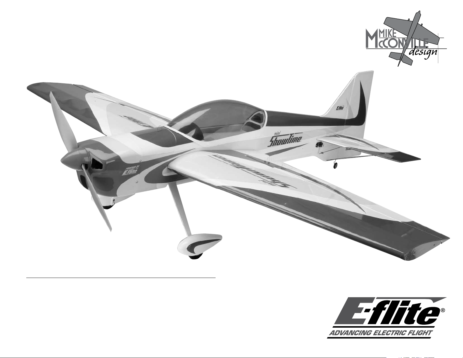
1. Place the landing gear onto the bottom of the fuselage.
It will angle forward when installed in the correct
3
/
direction. Attach with two 4-40 x
-inch socket head
8
screws and two #4 black washers.
Note: You may consider using a larger diameter wheel,
such as 2
1
/
-inch (58mm) (EFLA224), if your flying site
4
has rough terrain. By using a larger wheel, you will not
be able to use the included wheel pants.
8 E-flite Mini ShowTime ARF Assembly Manual
Page 9
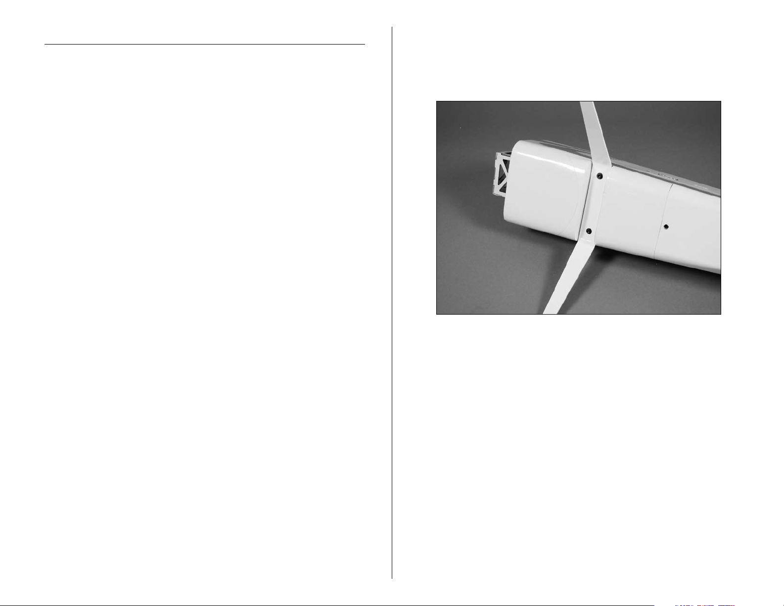
2. Slide the 4-40 x 1-inch machine screw through one of
3
1
/
the
-inch wheels. Slide a black #4 washer so it fits
4
against the wheel. Next secure a 4-40 lock nut against
the washer. Make sure the wheel still spins freely. Thread
a 4-40 nut onto the bolt. This nut will fit inside the wheel
pant and keep the wheel pant from rotating.
4. With the fuselage level to the work surface, rotate the
wheel pant so it is also level to your work surface. Mark
the location for the attachment screw using a felt-tipped
pen.
3. Attach the wheel to the landing gear using a black
#4 washer and 4-40 lock nut.
9E-flite Mini ShowTime ARF Assembly Manual
Page 10
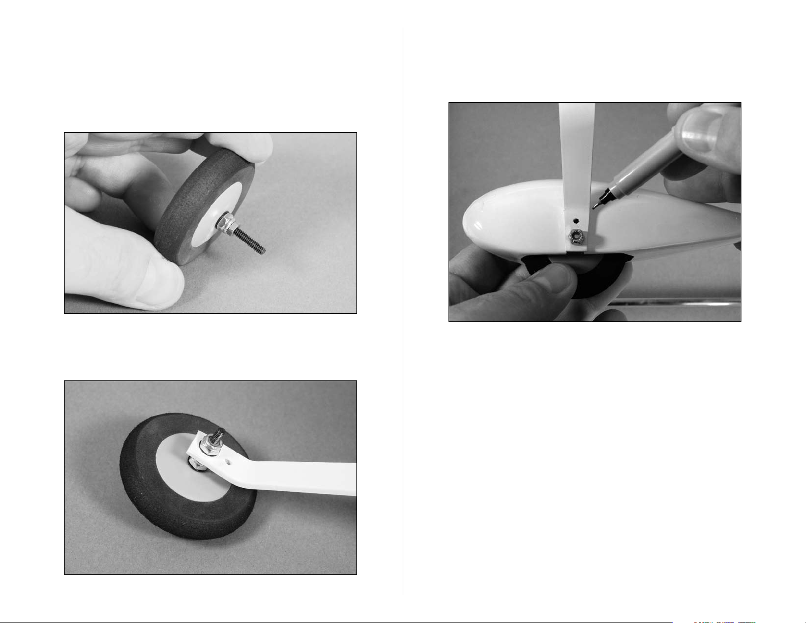
5. Use a drill and
location made in the previous step.
1
/
-inch drill bit to make a hole at the
16
6. Secure the pant to the landing gear with a 2mm x
6mm wood screw.
Outrunner Motor Installation
Required Parts
Fuselage
Brushless motor
4-40 x
#4 black washer (4)
Required Tools and Adhesives
Hex wrench:
Screwdriver (
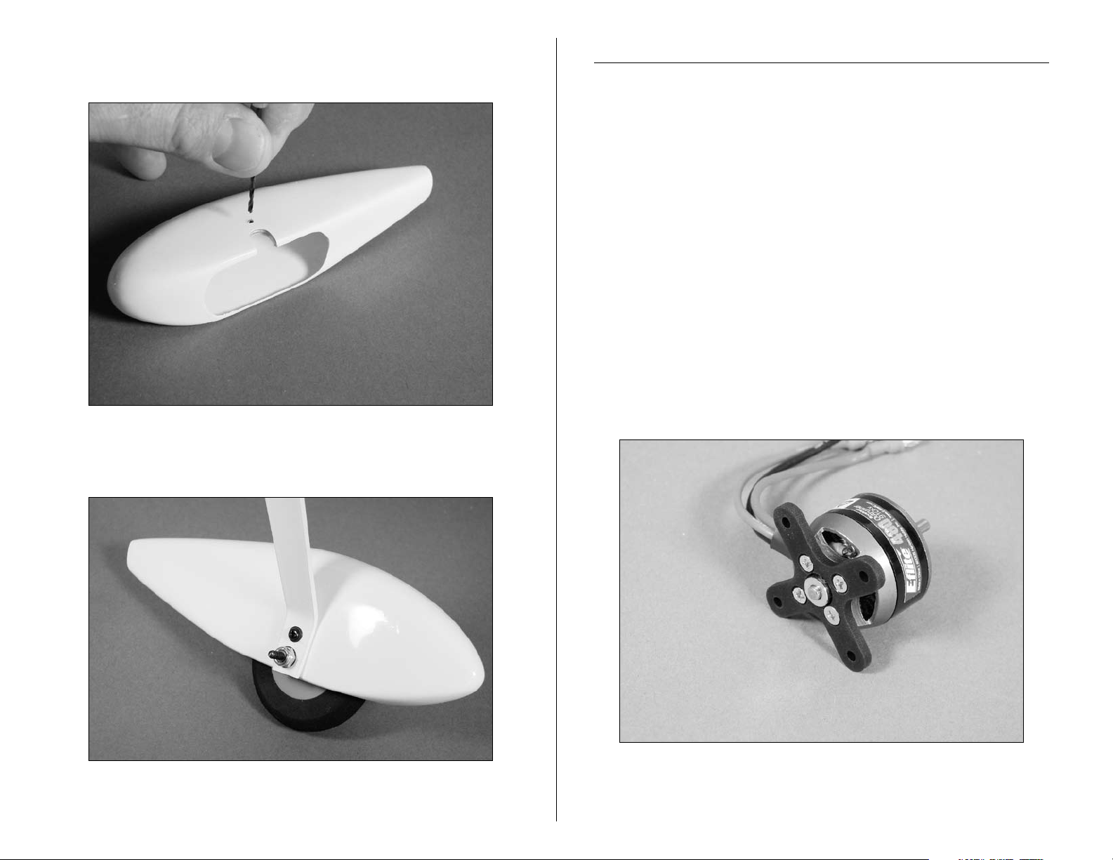
1. Attach the supplied aluminum motor X-mount to the
3
/
-inch socket head screw (4)
8
3
/
-inch
32
Phillips #0)
Note: This section covers the installation of the
recommended Park 480 Outrunner motor. The holes in
the firewall match the mounting pattern of the X-mount.
motor using the screws provided with the motor. The
wider section of the mount will be positioned toward
the motor wires.
7. Repeat Steps 2 through 6 for the remaining wheel
10 E-flite Mini ShowTime ARF Assembly Manual
and wheel pant.
Page 11
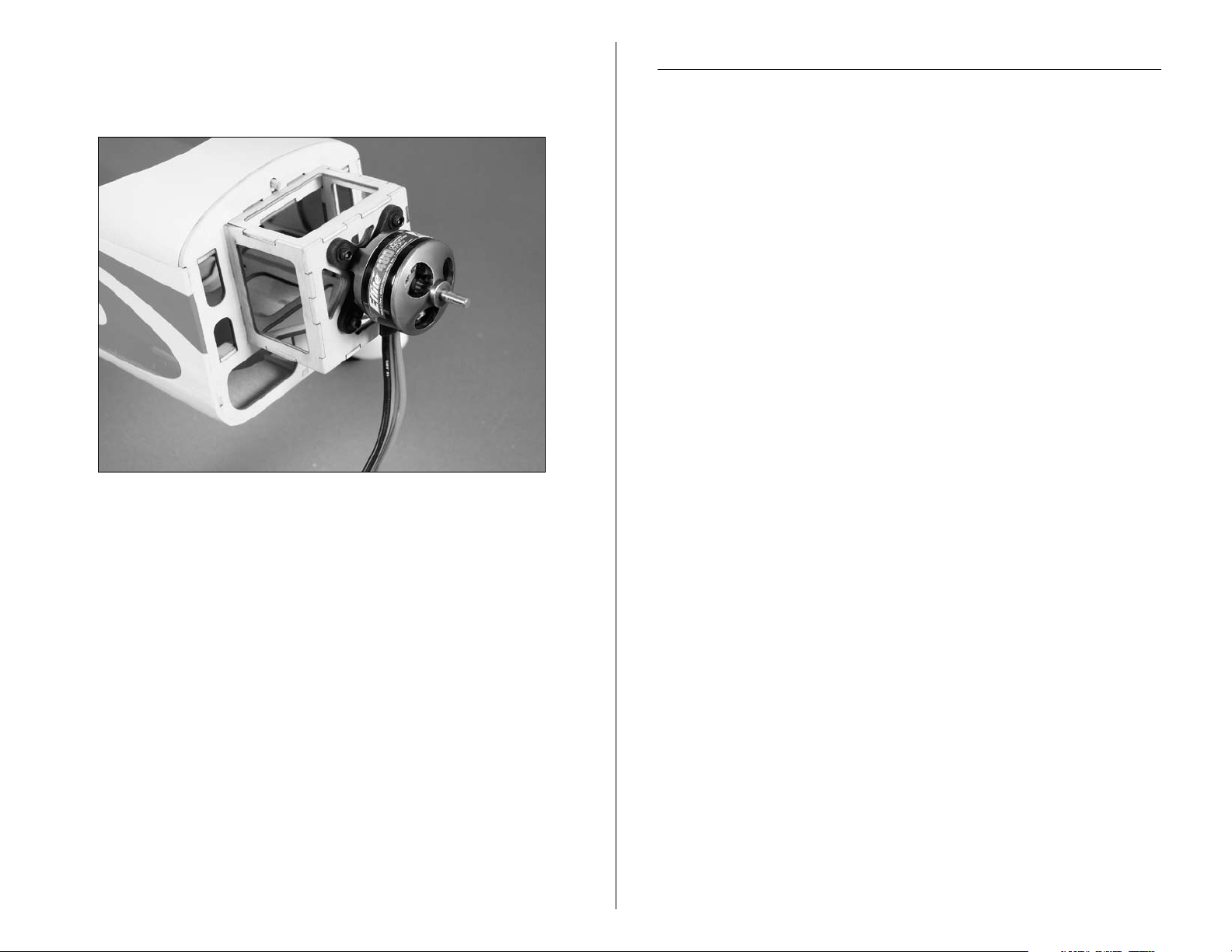
2. Attach the Outrunner motor to the front of the firewall
3
/
using four black #4 washers and four 4-40 x
-inch
8
socket head screws.
Cowling Installation
Required Parts
Fuselage w/motor installed
Cowling
2mm x 8mm wood screw (4)
Propeller
Spinner
Prop adapter (for outrunner motor)
Electronic speed control
Required Tools and Adhesives
Drill
1
/
Drill bit:
-inch (1.5mm),
16
Card stock
Masking tape
Screwdriver (Phillips #0)
Hook and loop material
Important Information About Your Brushless ESC
Make sure your ESC brake is programmed to Off. Also, be sure
to use an ESC with the proper 9V cutoff when using 3-cell Li-Po
packs, or 6V cutoff when using 2-cell Li-Po packs.
1
/
-inch (3mm)
8
Important Information About Your Propeller
It is also very important to check to be sure the propeller is
balanced before installing onto the shaft. An unbalanced
propeller may strip the gears or cause poor flight characteristics.
11E-flite Mini ShowTime ARF Assembly Manual
Page 12

1. Solder any connectors to the speed control to connect
to the motor battery and motor if necessary. Connect the
ESC to the motor and secure it to the bottom of the motor
box using hook and loop material. Actual ESC location
may vary but proper air flow and cooling is important.
3. Slide the propeller adapter through the hole in
the propeller.
2. Connect the speed control to the radio system and
motor battery. Check that the motor is rotating in the
correct direction. It will rotate counterclockwise when
viewed from the front of the aircraft. Use the instructions
with your speed control to correct a motor that is
operating in the wrong direction.
4. Slide the
adapter.
1
/
-inch (13mm) plastic washer onto the
2
12 E-flite Mini ShowTime ARF Assembly Manual
Page 13

5. Slide the spinner backplate onto the adapter. Thread
the propeller nut onto the adapter, but do not tighten it
at this time.
7. Slide the cowling on the fuselage. With the propeller
adapter on the motor shaft, position the cowl so there is
a gap between the spinner and cowling.
6. Tape four pieces of card stock to the fuselage to
indicate the locations for the cowl attaching screws and
the front edge of the fuselage.
8. Use a
the cowling and into the sides of the fuselage.
1
/
-inch (1.5mm) drill bit to drill holes through
16
13E-flite Mini ShowTime ARF Assembly Manual
Page 14

9. Enlarge the holes in the cowling ONLY using a
1
/
-inch (3mm) drill bit. Slide the cowling onto the
8
fuselage. Secure the cowling using four 2mm x 8mm
sheet metal screws.
10. Place the propeller back on the motor shaft
and tighten the adapter. Snap the spinner cone onto
the spinner.
Note: Make sure to check the balance of the propeller
Hint: Use thin CA to harden the holes drilled into the
after enlarging the hole in the propeller.
cowl mounting tabs. This will help to prevent the screws
from vibrating loose in flight.
14 E-flite Mini ShowTime ARF Assembly Manual
Page 15

Aileron Hinging
Required Parts
Wing (left and right)
Aileron (left and right)
CA hinges (8)
Required Tools and Adhesives
T-pins Thin CA
Drill Paper towel
Drill bit:
1
/
-inch (1.5mm)
16
2. Slide four hinges into the slits in the aileron. Center
the slot in the hinge with the hole drilled in Step 1. Place
a T-pin in each hinge to prevent it from being pushed into
the wing when installing the aileron.
1. Locate the positions for the hinges. Drill a
(1.5mm) hole in the center of each slot of both the wing
and aileron. This creates a tunnel for the CA, allowing
the CA to penetrate into the hinge better, bonding the
hinges more securely.
1
/
16
-inch
Note: Do not use CA accelerator during the hinging
process. The CA must be allowed to soak into the hinge
to provide the best bond. Using accelerator will not
provide enough time for this process.
15E-flite Mini ShowTime ARF Assembly Manual
Page 16

3. Slide the aileron into position. Check to make sure
it can move without interference at the wing root and
wing tip. Remove the T-pins and apply Thin CA to each
hinge. Make sure the hinge is fully saturated with CA.
Use a paper towel to clean up any excess CA from the
wing and aileron. Make sure to apply CA to both sides
of the hinge.
4. Firmly grasp the wing and aileron and gently pull on
the aileron to ensure the hinges are secure and cannot
be pulled apart. Use caution when gripping the wing and
aileron to avoid crushing the structure.
Note: Placing a #11 hobby blade between the aileron
leading edge and wing trailing edge to position the
aileron will result in a nice free-moving hinge for 3D
throws without any binding.
16 E-flite Mini ShowTime ARF Assembly Manual
Page 17

5. Work the aileron up and down several times to work
in the hinges and check for proper movement.
Aileron Servos and Linkages
Required Parts
Wing panel (right and left)
Micro control connector (2)
2mm x 4mm screw (2)
4-inch (102mm) pushrod (2)
Control horn and backplate (2)
Servos: S75 Sub-micro servo (2)
6-inch (150mm) servo extension (2)
Required Tools and Adhesives
Side cutters
Hobby knife
6-minute epoxy
String or dental floss
Phillips screwdriver (small)
Note: We suggest using the long 3D servo arms for
the Mini ShowTime. Replace all existing arms before
installing the servos.
6. Repeat Steps 1 through 5 for the remaining aileron.
1. Attach a 6-inch (150mm) servo extension. Use string
or dental floss to secure the servo lead and extension to
prevent them from unplugging in flight.
17E-flite Mini ShowTime ARF Assembly Manual
Page 18

2. Place the servo in the wing. Guide the servo lead out
through the opening at the wing root.
3. Secure the aileron servo using the screws provided
with the servo.
4. Use a hobby knife to enlarge the inboard hole in
the control horn to fit the 4-inch (102mm) long aileron
pushrod wire.
18 E-flite Mini ShowTime ARF Assembly Manual
Page 19

5. Repeat Steps 1 through 4 for the other wing panel.
6. Use 6-minute epoxy to attach the control horn to the
aileron. Attach the control horns for both the right and
left ailerons at this time.
7. Attach the micro control connector to both servo arms.
Be sure to use the included retainer to secure the micro
control connector to the servo arms.
19E-flite Mini ShowTime ARF Assembly Manual
Page 20

8. Turn on the radio system and center the aileron trim
and stick. Make sure the aileron servo is operating
properly using the transmitter. Slide the pushrod wire
through the micro connector. Install the servo arm parallel
to the aileron hinge line. Center the aileron, and secure
the position of the wire using the 2mm x 4mm screw and
a Phillips screwdriver.
Wing Installation
Required Parts
Fuselage Wing (right and left)
Wing tube #4 washer (silver) (2)
4-40 x
Required Tools and Adhesives
Hex wrench:
6-minute epoxy Pliers
1. Slide the wing tube into a wing panel.
1
/
-inch socket head screw (2)
2
3
/
-inch
32
9. Use side cutters to remove any excess wire, leaving
1
/
about
20 E-flite Mini ShowTime ARF Assembly Manual
(5mm) excess wire past the control connector.
4
2. Remove the hatch from the bottom of the fuselage
3
/
using a
-inch hex wrench.
32
Page 21

2. Slide the wing panel with tube into position
on the fuselage.
Stabilizer and Elevator
Required Parts
Fuselage w/wing installed
Stabilizer Elevator
CA hinge (4)
Required Tools and Adhesives
Hobby knife Felt-tipped pen
Ruler T-pins
Thin CA
1. Position the stabilizer into the slot in the aft end
of the fuselage. Check that the stabilizer is centered
in the fuselage.
3. Secure the wing panel using a 4-40 x
head screw with #4 washer (silver) using a
1
/
-inch socket
2
3
/
-inch hex
32
wrench.
4. Repeat Steps 2 and 3 for the remaining wing panel.
21E-flite Mini ShowTime ARF Assembly Manual
Page 22

2. Measure from the stab tip to the wing tip. Adjust the
A A
B B
A=A
B=B
Wing and Stabilizer Parallel
stab until the measurements are equal.
3. View the airframe from the rear and make sure the
wing and stab are parallel. If not, lightly sand the stab
saddle until they are.
4. Double-check the adjustments from Steps 1 through 3.
Use a felt-tipped pen to trace the outline of the fuselage
onto the top and bottom of the stabilizer.
5. Use a sharp hobby knife to cut the covering slightly
inside the lines drawn. Be very careful not to cut into the
underlying wood, as this will weaken the stab and cause
it to fail in flight.
Note: You can use a soldering iron instead of a knife.
This will eliminate the chances of cutting into the wood.
22 E-flite Mini ShowTime ARF Assembly Manual
Page 23

6. Slide the elevator into position, then the stabilizer.
7. Follow the same procedure for hinging the ailerons to
hinge the stabilizer/elevator. Use six hinges for this step.
Note: Start with the two hinges at the center nearest the
fuselage. Continue outward to the center hinges, then the
hinges at the tips. Be careful not to damage the joiner
section of the elevators.
8 . Check the alignment and make sure everything lines
up. Wick Thin CA into the joint between the fuselage and
stabilizer. Make sure to glue both top and bottom. Do
not use accelerator— to allow the CA to wick in the joint,
providing the best bond possible.
23E-flite Mini ShowTime ARF Assembly Manual
Page 24

Rudder and Fin
Required Parts
Fuselage Rudder
Fin CA hinge (3)
Tail wheel assembly
Required Tools and Adhesives
Hobby knife Thin CA
Felt-tipped pen Square
6-minute epoxy Medium grit sandpaper
1. Roughen the tail wheel assembly using medium grit
sandpaper. Use 6-minute epoxy to glue the tail wheel
assembly into the rudder.
2. Hinge the rudder and fin, using the same process
as described in Aileron Hinging. Use three hinges for
this process.
3. Place the fin in position on the fuselage. Trace the
outline of the fuselage onto both sides of the fin.
24 E-flite Mini ShowTime ARF Assembly Manual
Page 25

4. Remove the covering from the bottom of the fin using
the same technique used for the stabilizer.
5. Position the fin back onto the fuselage. Use a square to
check the alignment between the fin and stabilizer. Lightly
sand the bottom of the fin until the alignment is correct.
6. Use thin CA to glue the fin to the fuselage.
25E-flite Mini ShowTime ARF Assembly Manual
Page 26

Rudder and Elevator Servos
Required Parts
Fuselage
Micro control horn w/backplate (2)
5-inch (127mm) pushrod wire
2mm x 4mm screw (2)
5
5
/
-inch (143mm) pushrod wire
8
Micro control connector w/retainer (2)
Carbon rod, 8-inch (204mm) (4)
Servo (2)
12-inch (305mm) servo extension (2)
Required Tools and Adhesives
Phillips screwdriver (small) Hobby knife
6-minute epoxy
1. Secure an 18-inch (457mm) servo extension to the
servo. Mount the elevator servo using the hardware
provided with the servo.
2. Use a hobby knife to enlarge the inboard hole
in one of the remaining control horns. Attach the
5-inch (127mm) pushrod wire to the control horn.
3. Attach the micro control horn to the elevator using the
control horn backplate and 6-minute epoxy.
Hint: It is easiest to pass the extension through the former,
then to the rear of the fuselage and retrieve it at the
opening for the servo.
26 E-flite Mini ShowTime ARF Assembly Manual
Page 27

4. Install the micro control connector onto the
elevator servo arm. Pass the elevator pushrod wire
through the connector. With the radio on and elevator
trim centered, center the elevator. Secure the elevator
pushrod wire using the 2mm x 4mm screw and a small
Phillips screwdriver.
Note: The Mini ShowTime is designed to use an optional
pull-pull rudder linkage when using a lightweight motor
and battery. The items for the pull-pull system are
available separately.
5. Repeat Steps 1 through 4 for the rudder servo and
5
5
/
linkage using the
-inch (143mm) pushrod wire.
8
27E-flite Mini ShowTime ARF Assembly Manual
Page 28

6. Attach the 8-inch (204mm) carbon stabilizer supports
between the fuselage and stabilizer. Make notches in the
stabilizer and fuselage for the rods to rest in. Secure the
rods using 6-minute epoxy.
Final Assembly
Required Parts
Fuselage
Wing
Canopy
Receiver
Battery
Battery hatch
4-40 x 1-inch socket head bolt (2)
#4 washer (2)
Hook and loop tape
Hook and loop strap
Required Tools and Adhesives
3
/
Hex wrench:
Felt-tipped pen
Canopy glue
32
-inch
Note: Make sure the rods are positioned so they
don't interfere with the operation of the rudder and
elevator linkages.
28 E-flite Mini ShowTime ARF Assembly Manual
Page 29

1. Plug in the elevator and rudder servos and ESC into
the receiver. Mount the receiver to the inside of the
fuselage using hook and loop material. Route the antenna
wire through the bottom of the fuselage to the rear, or as
directed by your radio instruction manual.
2. Replace the bottom hatch on the fuselage and secure it
using the two 4-40 screws.
3. Place the canopy into position on the fuselage. Use
a felt-tipped pen to trace the outline of the canopy onto
the fuselage.
Note: Do not cut or change the length of the antenna
wire, as this will reduce the range of your radio system.
29E-flite Mini ShowTime ARF Assembly Manual
Page 30

4. Use medium grit sandpaper to roughen the covering
1
/
-inch (3mm) inside the line drawn. Also roughen the
8
1
/
outside
-inch (3mm) of the canopy. Clean the sanded
8
areas using a paper towel and rubbing alcohol.
5. Use Formula 560 canopy glue to glue the canopy to
the fuselage. Use masking tape to hold the canopy in
position until the glue fully cures.
6. Remove the battery hatch from the fuselage by pulling
upward on the tab.
30 E-flite Mini ShowTime ARF Assembly Manual
Page 31

7. With the aircraft fully assembled, install the battery
into the battery compartment. Secure the battery using
the hook and loop tape and the hook and loop straps.
Optional Side Force
Generator Installation
Required Parts
Assembled airframe
-inch
™
(2)
Side Force Generator
1
/
4-40 x
-inch machine screw (4)
2
Spacers
Required Tools and Adhesives
Hobby knife
Hex wrench:
3
/
32
Felt-tipped pen
Note: Place a piece of hook and loop tape on the bottom
of the battery and on the fuselage where the battery
rests. This will keep the battery from shifting forward or
backward during extreme maneuvers.
1. Slide two 4-40 x
the Side Force Generator. Place a spacer onto each of
the screws as shown.
1
/
-inch screws through the holes in
2
31E-flite Mini ShowTime ARF Assembly Manual
Page 32

2. Remove the covering from the blind nuts in the wing
using a hobby knife. Attach the Side Force Generator to
the wing.
Center of Gravity
An important part of preparing the aircraft for flight is properly
balancing the model.
Caution: Do not inadvertently skip this step!
3. Repeat Steps 1 and 2 for the remaining
Side Force Generator.
The recommended Center of Gravity (CG) location for the
1
4
/
Mini ShowTime is
inches (114mm) back measured from the
2
center of the leading edge of the wing next to the fuselage.
After your first flights, the Center of Gravity can be adjusted for
personal preference.
32 E-flite Mini ShowTime ARF Assembly Manual
Page 33

Control Throws
The control throw measurements are taken at the widest
point on the surface.
1. Turn on the transmitter and receiver of your aircraft.
Check the movement of the rudder using the transmitter.
When the stick is moved right, the rudder should also
move right. Reverse the direction of the servo at the
transmitter if necessary.
2. Check the movement of the ailerons using the
transmitter. When the stick is moved right, the right
aileron will move up and the left aileron will move
down. Reverse the direction of the servo at the transmitter
if necessary.
3. Check the movement of the elevator with the radio
system. Moving the elevator stick down will make the
airplane elevator move up.
4. Use a throw gauge to adjust the throw of the elevator,
ailerons and rudder. Adjust the position of the pushrod
at the control horn, or the travel/endpoint adjustments
of your computer transmitter, to achieve the following
measurements when moving the sticks to their endpoints.
Low Rate High Rate
Ailerons:
Up
Down
3
/
-inch (19mm) 2
4
3
/
-inch (19mm) 2
4
1
/
-inch (63mm)
2
1
/
-inch (63mm)
2
Elevator:
Up
Down
3
/
-inch (19mm) 2
4
3
/
-inch (19mm) 2
4
1
/
-inch (57mm)
4
1
/
-inch (57mm)
4
Rudder:
Right 1-inch (25mm) 4-inch (102mm)
Left 1-inch (25mm) 4-inch (102mm)
These are general guidelines measured from our own
flight tests. You can experiment with higher rates to match
your preferred style of flying.
Range Test Your Radio
1. Before each flying session, be sure to range check
your radio. This is accomplished by turning on your
transmitter with the antenna collapsed. Turn on the
receiver in your airplane. With your airplane on the
ground and the engine running, you should be able to
walk 30 paces (approximately 100 feet) away from your
airplane and still have complete control of all functions.
If not, don’t attempt to fly! Have your radio equipment checked
out by the manufacturer.
2. Double-check that all controls (aileron,elevator, rudder
and throttle) move in the correct direction.
3. Be sure that your transmitter batteries are
fully charged, per the instructions included
with your radio.
33E-flite Mini ShowTime ARF Assembly Manual
Page 34

Preflight
Flying Your Mini ShowTime
Check Your Radio
Before going to the field, be sure that your batteries are fully
charged per the instructions included with your radio. Charge
both the transmitter and receiver pack for your airplane. Use
the recommended charger supplied with your particular radio
system, following the instructions provided with the radio. In
most cases, the radio should be charged the night before going
out flying.
Before each flying session, be sure to range check your radio.
See your radio manual for the recommended range and
instructions for your radio system. Each radio manufacturer
specifies different procedures for their radio systems. Next, start
the motor. With the model securely anchored, check the range
again. The range test should not be significantly affected. If it is,
don’t attempt to fly! Have your radio equipment checked out by
the manufacturer.
Note: Keep loose items that can get entangled in
the propeller away from the prop. These include
loose clothing, or other objects such as pencils and
screwdrivers. Especially keep your hands away from the
propeller.
Double-check that all controls (aileron, elevator, rudder and
throttle) move in the correct direction.
Check the radio installation and make sure all the control
surfaces are moving correctly (i.e. the correct direction and with
the recommended throws). Test run the motor and make sure
it transitions smoothly from off to full throttle and back. Also
ensure the engine is installed according to the manufacturer’s
instructions, and it will operate consistently.
Flying the Mini ShowTime is about as fun as it can get at the
park. A very light wing loading and extreme control throws
make for some exciting 3D flying. Verify that your CG is at the
correct location as per the manual and that you have your rates
set up to your liking. Verify all control throws are in the correct
direction and the motor spins in the correct direction as well.
Point the model into the wind and add some throttle trim until
the motor begins to turn. This will be your flight idle. Now,
apply power slowly. You will find the model will become
airborne very quickly and at a low speed. This model excels
at flying slow and easy as well as fast and extreme. Trim the
model for level flight at half throttle. Only use full throttle for
maneuvering. It is not recommended to fly this model fast or
at full throttle in level flight. Doing this can result in the flight
controls fluttering and a potential catastrophic failure of the
airframe.
You will find you can adjust the CG to your liking by moving
the battery pack fore or aft indide the fuselage. Also keep the
battery on the fuselage mounted high (at least at wing centerline
or above) to help in hovering maneuvers and harriers.
To land the Mini ShowTime just reduce the throttle to idle and
feed in up elevator until the model settles into a slightly nose
high attitude. Gently fly the model down to the landing spot with
a final flair at touchdown. You will find the model will have a
very short roll out. We hope you enjoy the Mini ShowTime as
much as we do.
Happy landings.
Check all the control horns, servo horns, and clevises to make
sure they are secure and in good condition. Replace any items
that would be considered questionable. Failure of any of these
components in flight would mean the loss of your aircraft.
34 E-flite Mini ShowTime ARF Assembly Manual
Page 35

2007 Official AMA National Model Aircraft Safety Code
GENERAL
1) I will not fly my model aircraft in sanctioned events, air shows
or model flying demonstrations until it has been proven to be
airworthy by having been previously, successfully flight tested.
2) I will not fly my model higher than approximately 400 feet within 3
miles of an airport without notifying the airport operator. I will give
right-of-way and avoid flying in the proximity of full-scale aircraft.
Where necessary, an observer shall be utilized to supervise flying
to avoid having models fly in the proximity of full-scale aircraft.
3) Where established, I will abide by the safety rules for the flying
site I use, and I will not willfully or deliberately fly my models in a
careless, reckless and/or dangerous manner.
4) The maximum takeoff weight of a model is 55 pounds, except
models flown under Experimental Aircraft rules.
5) I will not fly my model unless it is identified with my name and
address or AMA number on or in the model. (This does not apply
to models while being flown indoors.)
6) I will not operate models with metal-bladed propellers or with
gaseous boosts, in which gases other than air enter their internal
combustion engine(s); nor will I operate models with extremely
hazardous fuels such as those containing tetranitromethane or
hydrazine.
RADIO CONTROL
1) I will have completed a successful radio equipment ground range
check before the first flight of a new or repaired model.
2) I will not fly my model aircraft in the presence of spectators until I
become a qualified flier, unless assisted by an experienced helper.
3) At all flying sites a straight or curved line(s) must be established
in front of which all flying takes place with the other side for
spectators. Only personnel involved with flying the aircraft are
allowed at or in front of the flight line. Intentional flying behind the
flight line is prohibited.
4) I will operate my model using only radio control frequencies
currently allowed by the Federal Communications Commission.
(Only properly licensed Amateurs are authorized to operate
equipment on Amateur Band frequencies.)
5) Flying sites separated by three miles or more are considered safe
from site-to-site interference, even when both sites use the same
frequencies. Any circumstances under three miles separation
require a frequency management arrangement, which may be
either an allocation of specific frequencies for each site or testing
to determine that freedom from interference exists. Allocation plans
or interference test reports shall be signed by the parties involved
and provided to AMA Headquarters.
Documents of agreement and reports may exist between (1) two
or more AMA Chartered Clubs, (2) AMA clubs and individual
AMA members not associated with AMA Clubs, or (3) two or
more individual AMA members.
6) For Combat, distance between combat engagement line
and spectator line will be 500 feet per cubic inch of engine
displacement. (Example: .40 engine = 200 feet.); electric motors
will be based on equivalent combustion engine size. Additional
safety requirements will be per the RC Combat section of the
current Competition Regulations.
7) At air shows or model flying demonstrations, a single straight line
must be established, one side of which is for flying, with the other
side for spectators.
8) With the exception of events flown under AMA Competition rules,
after launch, except for pilots or helpers being used, no powered
model may be flown closer than 25 feet to any person.
9) Under no circumstances may a pilot or other person touch a
powered model in flight.
35E-flite Mini ShowTime ARF Assembly Manual
Page 36

10245
© 2007 Horizon Hobby, Inc.
4105 Fieldstone Road
Champaign, Illinois 61822
(877) 504-0233
horizonhobby.com
E-fliteRC.com
 Loading...