

Page 1
Extra 300 32e ARF
Assembly Manual
Specifications
Wingspan: 52.5 inches (1335mm)
Wing Area: 542 sq in (34.2 sq dm)
Length: 49.0 inches (1245mm)
Weight w/Battery: 4.40 – 4.60 lb (1.90–2.10 kg)
Weight w/o Battery: 3.70 – 3.90 lb (1.60–1.80 kg)
Page 2
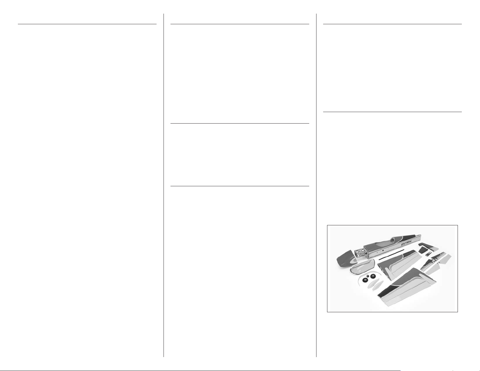
Table of Contents
Introduction
Using the Manual
Specifications ......................................................... 1
Introduction ........................................................... 2
Important Information Regarding
Warranty Information ........................................ 2
Covering Colors ..................................................... 2
Using the Manual ................................................... 2
Contents of Kit/Parts Layout .................................... 2
Recommended Radio Equipment ............................. 3
Required Tools and Adhesives ................................. 3
Brushless Outrunner Setup ...................................... 3
Optional Accessories .............................................. 3
Note on Lithium Polymer Batteries ........................... 3
Warning ................................................................ 3
Aileron Installation ................................................. 4
Aileron Servo Installation ........................................ 6
Motor Installation ................................................... 9
Cowling and Spinner Installation ........................... 10
Landing Gear and Wheel Installation .................... 12
Fuselage Servo and Receiver Installation ................ 13
Stabilizer Installation ............................................ 15
Elevator Installation .............................................. 18
Fin Installation ...................................................... 21
Rudder and Tail Wheel Installation ........................ 22
Rudder Pull-Pull Cable Installation.......................... 25
Wing Installation .................................................. 28
Battery Installation ................................................ 29
Canopy Installation .............................................. 29
Center of Gravity ................................................. 30
Control Throws..................................................... 30
Preflight ............................................................... 31
Flying Your Extra 300 32e ARF ............................. 31
Range Test Your Radio .......................................... 31
Safety Do’s and Don’ts for Pilots ............................ 32
Daily Flight Checks ............................................... 32
Warranty Information ........................................... 32
Compliance Information for the European Union .... 34
2009 Official Academy of
Model Aeronautics Safety Code ....................... 34
Designed by veteran IMAC and XFC competitor, Mike
McConville, the Extra 300 32e ARF is optimized
to deliver unlimited 3D and precision aerobatic
performance using the latest in brushless motor
technology. And while it is IMAC legal, you don’t have
to be a competitive pilot to appreciate its incredible
performance. Any intermediate to experienced pilot
will enjoy its “big plane” handling characteristics and
gorgeous scale lines whether they’re out for a trophy
or simply out for a good time.
Important Information
Regarding Warranty Information
Please read our Warranty and Liability Limitations
section on Page 32 before building this product. If you
as the Purchaser or user are not prepared to accept the
liability associated with the use of this Product, you are
advised to return this Product immediately in new and
unused condition to the place of purchase.
Covering Colors
White HANU870
Flame Red HANU883
Silver HANU881
Midnight Blue HANU885
This manual is divided into sections to help make
assembly easier to understand, and to provide breaks
between each major section. In addition, check boxes
have been placed next to each step to keep track
of its completion. Steps with a single circle () are
performed once, while steps with two circles ( )
indicate the step requires repeating, such as for a right
or left wing panel, two servos, etc.
Remember to take your time and follow the directions.
Contents of Kit/Parts Layout
Replacement Parts
EFL4126 Wing Set
EFL4127 Fuselage
EFL4128 Horizontal Tail Set
EFL4129 Vertical Tail Set
EFL4130 Tail Support
EFL4131 Cowling
EFL4132 Canopy
EFL4133 Main Landing Gear
EFL4134 Wheel Pant Set
EFL4135 Wing Tube
EFL4136 Control Hardware
EFL4137 Wheel Set
EFL4138 Hardware Set
2 E-flite Extra 300 32e ARF Assembly Manual
Page 3
Recommended Radio Equipment
Required Tools and Adhesives
Note on Lithium Polymer Batteries
You will need a minimum 6-channel transmitter,
receiver and four servos. You can choose to purchase
a complete radio system. If you are using an
existing transmitter, just purchase the other required
equipment separately. We recommend the crystalfree, interference-free Spektrum™ DX6i 2.4GHz DSM®
6-channel system. If using your own transmitter, we
recommend the JR SPORT™ MN48 Mini servos.
If you own a Spektrum radio, just add a DSM2
and four JR SPORT MN48 mini servos. We show the
installation of the AR6200 receiver in the manual.
Transmitter
SPM6600 DX6i 6-Channel Full Range w/o
Servos MD2
Or Purchase Separately
SPMAR6200 DSM2 AR6200 6-Channel
Receiver Ultralite
And
JSP20040 MN48 Mini Servo (4)
JSP98100 3-inch (76mm) Servo Extension
JSP98110 6-inch (152mm)
Servo Extension (2)
JSP98120 18-inch (457mm)
Servo Extension
JRPA215 Heavy-Duty Servo Horn (2)
™
receiver
Tools & Equipment
Crimping tool Side Cutters
Epoxy brushes Felt-tipped pen
Flat file Hobby knife (#11 blade)
Hobby scissors Low-tack Tape
Mixing cup Medium grit sandpaper
Mixing stick Nut Driver 7mm
Paper towel Pencil
Petrolium jelly Phillips screwdriver: #1, #2
Pin vise Pliers (2)
Rubbing alcohol Ruler
Square String
T-pins Toothpicks
Adjustable wrench
Open end or box wrench: 10mm
Ball driver or hex wrench: 3/32 inch, 1.5mm
Drill bit: 1/16-inch (1.5mm), 5/64-inch (2mm)
Adhesives
Threadlock Thin CA
Canopy glue 30-minute epoxy
Brushless Outrunner Setup
EFLM4032A Power 32 Brushless Outrunner
Motor, 770Kv
APC14070E APC 14x7E Propeller or
APC13065E APC 13x6.5E Propeller
EFLA1060 60-Amp Pro Switch-Mode BEC
Brushless ESC
THP38504SP30 3850mAh 4S 14.8V Pro Power
30C Li-Po
EFLSP225 21/4 inch Aluminum Spinner
Lithium Polymer batteries are significantly
more volatile than alkaline or Ni-Cd/
Ni-MH batteries used in RC applications.
All manufacturer’s instructions and warnings
must be followed closely. Mishandling of
Li-Po batteries can result in fire. Always
follow the manufacturer’s instructions when
disposing of Lithium Polymer batteries.
Warning
An RC aircraft is not a toy! If misused, it can cause
serious bodily harm and damage to property. Fly
only in open areas, preferably at AMA (Academy of
Model Aeronautics) approved flying sites, following all
instructions included with your radio.
Keep loose items that can get entangled in the
propeller away from the prop, including loose clothing,
or other objects such as pencils and screwdrivers.
Especially keep your hands away from the propeller.
During the course of building your model we suggest
that you use a soft base for the building surface.
Such things as a foam stand, large piece of bedding
foam or a thick bath towel will work well and help
protect the model from damage during assembly.
This is not shown in the assembly photographs to
display the detail of the actual building of the model.
The Spektrum trademark is used with permission
of Bachmann Industries, Inc.
Optional Accessories
EFLA110 Power Meter
EFLC505 Intelligent 1- to 5-Cell
Balancing Charger
3E-flite Extra 300 32e ARF Assembly Manual
Page 4
Aileron Installation
Required Parts
Wing panel with aileron (right and left)
CA hinge (10 total)
Required Tools and Adhesives
Pin vise T-pins
Ruler Drill bit: 1/16-inch (1.5mm)
Thin CA Hobby knife with #11 blade
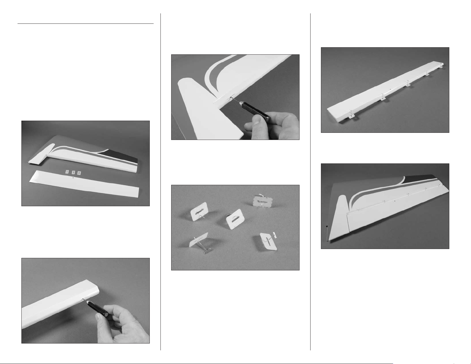
1. Locate one of the wing panels. Separate the
aileron from the wing. Remove the hinges and set
them aside.
3. Use a pin vise and 1/16-inch (1.5mm) drill bit
to drill a hole in the center of each of the hinge
slots in the wing. Note that there are five (5) slots,
even though only three (3) hinges were removed in
the previous step.
4. Place a T-pin in the center of each of the hinges
as shown. You will need to prepare five (5) hinges
in this step. The additional hinges have been
supplied with your model.
5. Insert the hinges in the slots of the aileron.
The T-pins will keep the hinges centered so they
are positioned equally in the aileron and wing
when installed.
6. Position the aileron by sliding the hinges into the
slots in the wing.
2. Use a pin vise and 1/16-inch (1.5mm) drill bit
to drill a hole in the center of each of the hinge
slots in the aileron. Note that there are five (5)
slots, even though only three (3) hinges were
removed in the previous step.
4 E-flite Extra 300 32e ARF Assembly Manual
Page 5
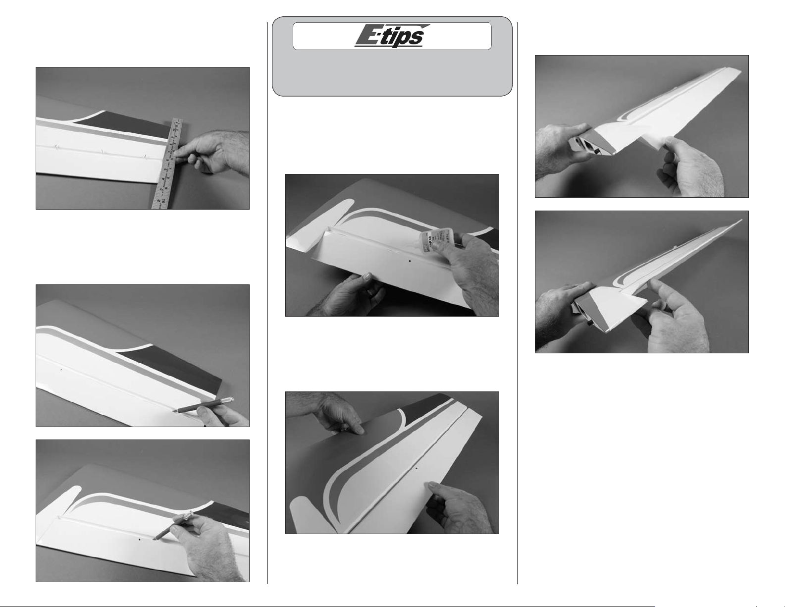
7. Check the alignment of the aileron. Use a ruler
to make sure the end of the aileron is aligned
evenly with the wing tip.
8. Remove the T-pins from the hinges. Set the hinge
gap using a hobby knife with a #11 blade. The
blade should just fit in the gap between the aileron
and wing.
11. Flex the aileron through its range of motion a
few times to break in the aileron hinges.
When hinging the aileron, do not use CA accelerator.
The CA must be allowed to penetrate the hinge or
the bond between the hinge and wood could fail.
9. Flex the aileron slightly so the hinges can be
seen. Make sure not to change the hinge gap in the
process. Saturate the hinges using thin CA on both
the top and bottom of the hinge to both sides of the
wing and aileron.
10. After the CA has fully cured, check to make
sure the hinges are secure by gently pulling on the
aileron and wing. If you find any loose hinges,
apply more CA to the hinge and recheck.
12. Repeat Steps 1 through 11 to join the
remaining aileron to its wing panel.
5E-flite Extra 300 32e ARF Assembly Manual
Page 6
Aileron Servo Installation
Required Parts
Nylon clevis (2) Clevis retainer (2)
Assembled wing panel (right and left)
Control horn screw with hardware (2)
Servo extension, 6-inch (152mm) (2)
Aileron linkage wire, 21/2-inch (64mm) (2)
Radio system
Servo with accessories (2)
Heavy-duty servo horn (2)
Nylon control horn (2)
Required Tools and Adhesives
Pliers Phillips screwdriver: #1, #2
String Pencil
Thin CA Threadlock
Pin vise String
Drill bit: 1/16-inch (1.5mm), 5/64-inch (2mm)
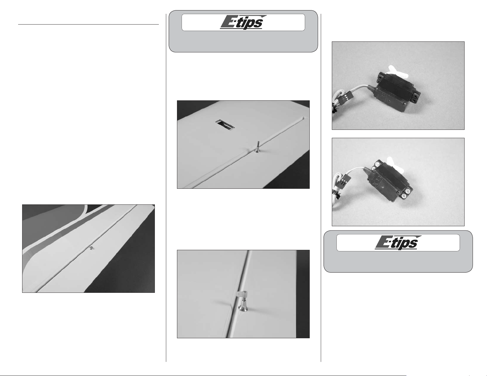
1. Remove the tapered nut and one countersink
from the control horn screw. Slide the screw and
remaining countersink into the hole in the aileron.
The screw must exit to the bottom of the wing.
4. Prepare the servo by installing the grommets
and brass eyelets as described in the instructions
with the servo or your radio system.
Always use threadlock on metal-to-metal fasteners
to prevent them from vibrating loose.
2. Slide the countersink back onto the control
horn screw. The tapered nut is then threaded on
the screw to secure its position on the aileron.
Use a #2 Phillips screwdriver and pliers to
tighten the hardware.
3. Thread the nylon control horn on the control
horn screw. The top of the control horn must be
flush with the top of the screw when installed. It
may be necessary to use a #2 Phillips screwdriver
to keep the control horn screw from rotating when
installing the control horn.
Prepare the elevator and rudder
servos at this time as well.
6 E-flite Extra 300 32e ARF Assembly Manual
Page 7
5. Secure a 6-inch (152mm) servo extension to the
aileron servo lead using string or a commercially
available connector. This will keep the servo and
lead from disconnecting inside the wing.
6. Insert the extension into the opening for the
aileron servo. Guide the extension through the
wing and out of the wing root as shown.
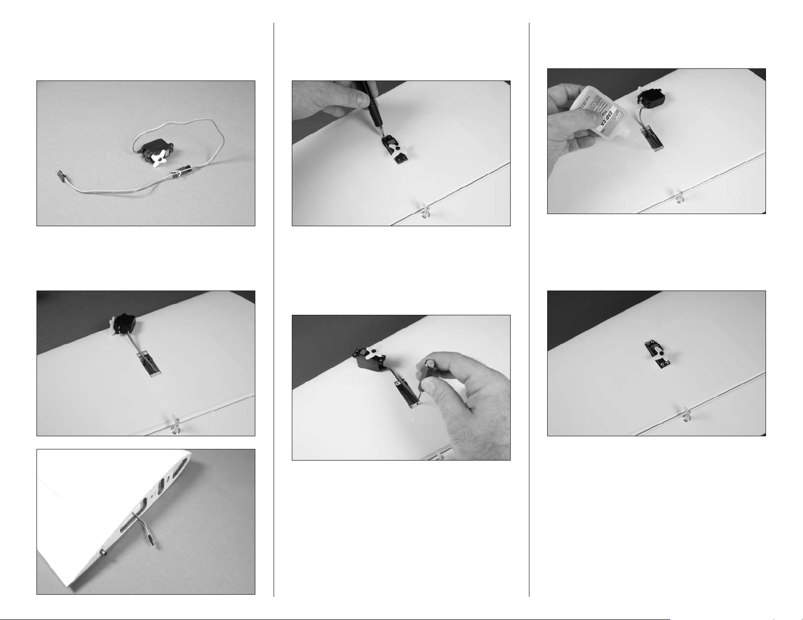
7. Position the servo in the servo opening. Make
sure it is centered and not touching the sides of the
opening. Use a pencil to mark the locations for the
servo mounting screws.
8. Move the servo and use a pin vise with a 1/16-
inch (1.5mm) drill bit to drill the holes for the
aileron servo mounting screws. Use care not to
accidentally drill through the covering on the top of
the wing.
9. Apply 2–3 drops of thin CA in each of the holes
to harden the surrounding wood. This will make the
screws more secure when they are installed.
10 Use the screws provided with the servo to
secure it in the wing. Note that the output of
the servo faces to the aileron. Use a #1 Phillips
screwdriver to tighten the screws.
7E-flite Extra 300 32e ARF Assembly Manual
Page 8
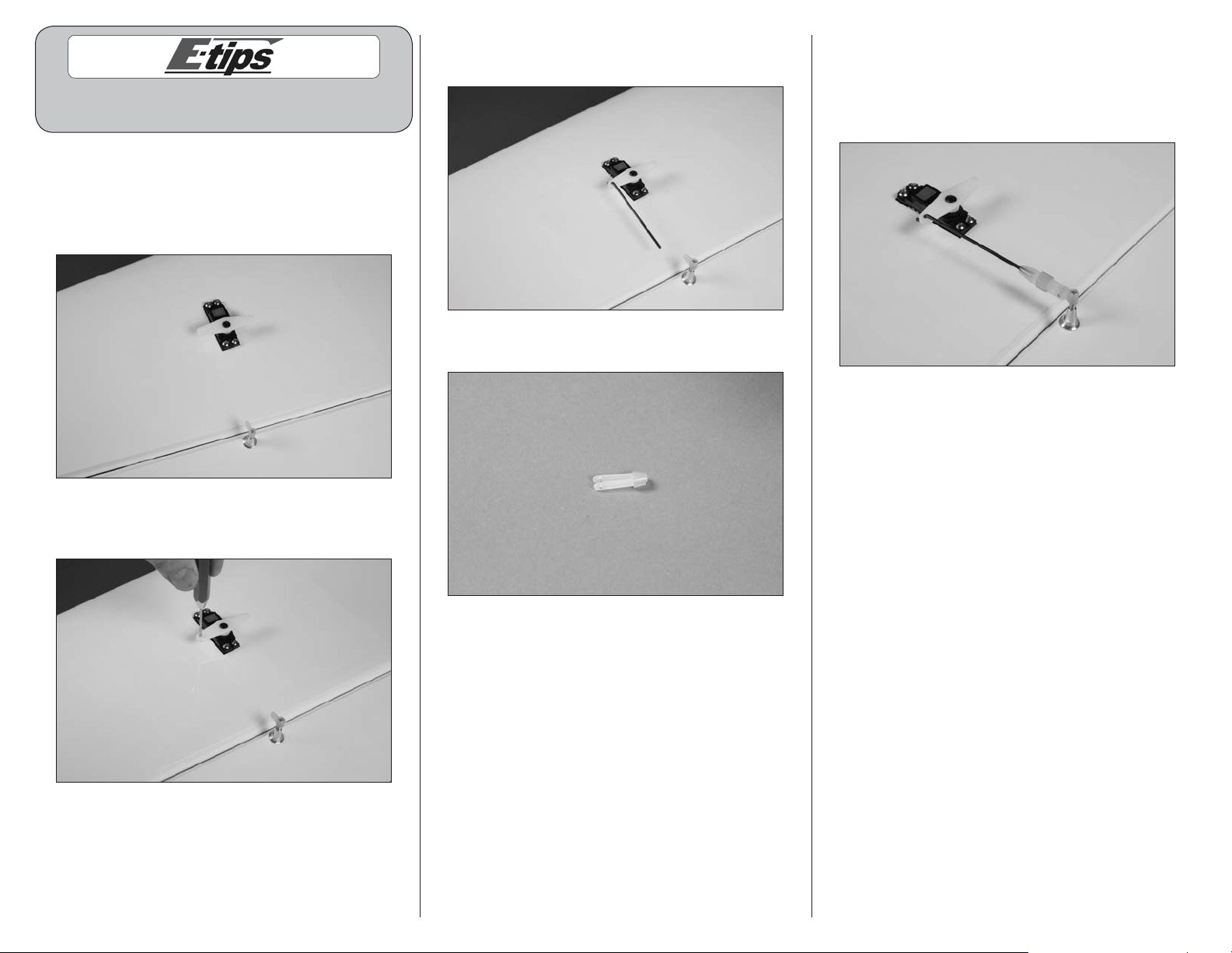
When installing the servo horn on the aileron servo it
must be positioned parallel to the aileron hinge line.
11. Use a #1 Phillips screwdriver to remove the
stock servo horn from the servo. Use the radio
system to center the aileron servo. Attach a heavyduty servo horn to the servo using the screw from
the servo and a #1 Phillips screwdriver.
13. Insert the Z-bend of the 21/2-inch (64mm) linkage
wire into the hole in the servo horn as shown.
14. Slide a clevis retainer on a clevis as shown.
15. Thread the clevis on the aileron linkage wire.
With the radio system on, adjust the clevis so the
aileron is aligned when the clevis is attached to the
control horn. Slide the clevis retainer over the forks
of the clevis to prevent it from opening in flight.
16. Repeat Steps 1 through 15 to install the
remaining aileron servo.
12. Use a pin vise and a 5/64-inch (2mm) drill bit
to enlarge the outer hole in the servo horn.
8 E-flite Extra 300 32e ARF Assembly Manual
Page 9
Motor Installation
Required Parts
Fuselage Motor spacer (4)
Speed control Motor with accessories
#4 washer (4) Hook and loop tape
4-40 x 1-inch socket head screw (4)
Servo extension, 3-inch (76mm)
Required Tools and Adhesives
String Threadlock
Phillips screwdriver: #1, #2
Ball driver or hex wrench: 3/32-inch
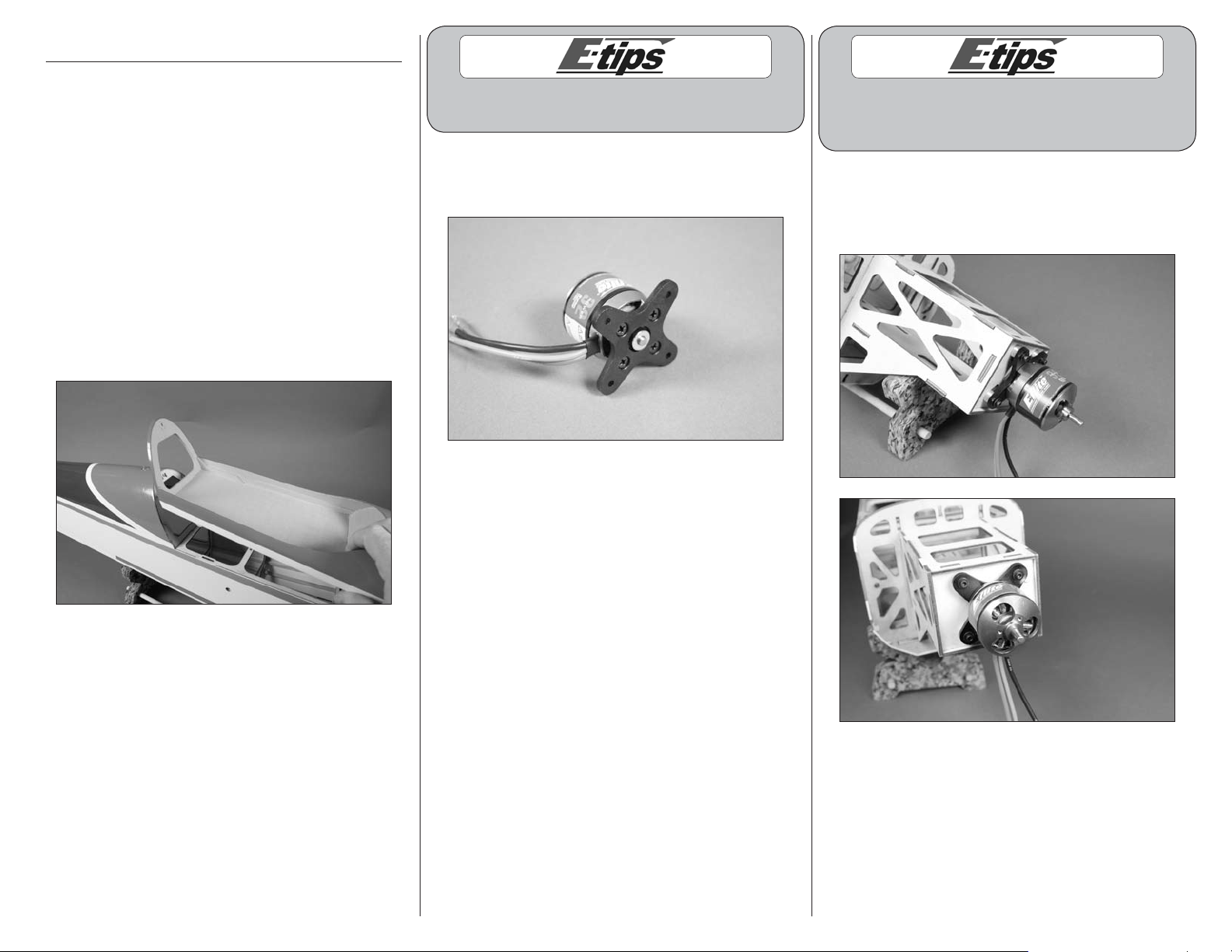
1. Remove the canopy hatch from the fuselage by
sliding the hatch pin rearward and lifting the hatch
from the fuselage.
Always use threadlock on metal-to-metal fasteners
to prevent them from vibrating loose.
2. Use a #2 Phillips screwdriver to attach the
X-mount to the motor using the screws provided
with the motor.
The blind nuts in the firewall can be positioned
for a variety of motors. You will need to adjust
their position to mount your particular motor
3. Use four (4) aluminum motor spacers, four (4)
#4 washers and four (4) 4-40 x 1-inch socket head
screws to attach the motor to the firewall. Tighten the
screws using a 3/32-inch ball driver or hex wrench.
9E-flite Extra 300 32e ARF Assembly Manual
Page 10
Matching the colors between the ESC and motor
when they are connected will result in the correct
motor direction if using all E-flite components.
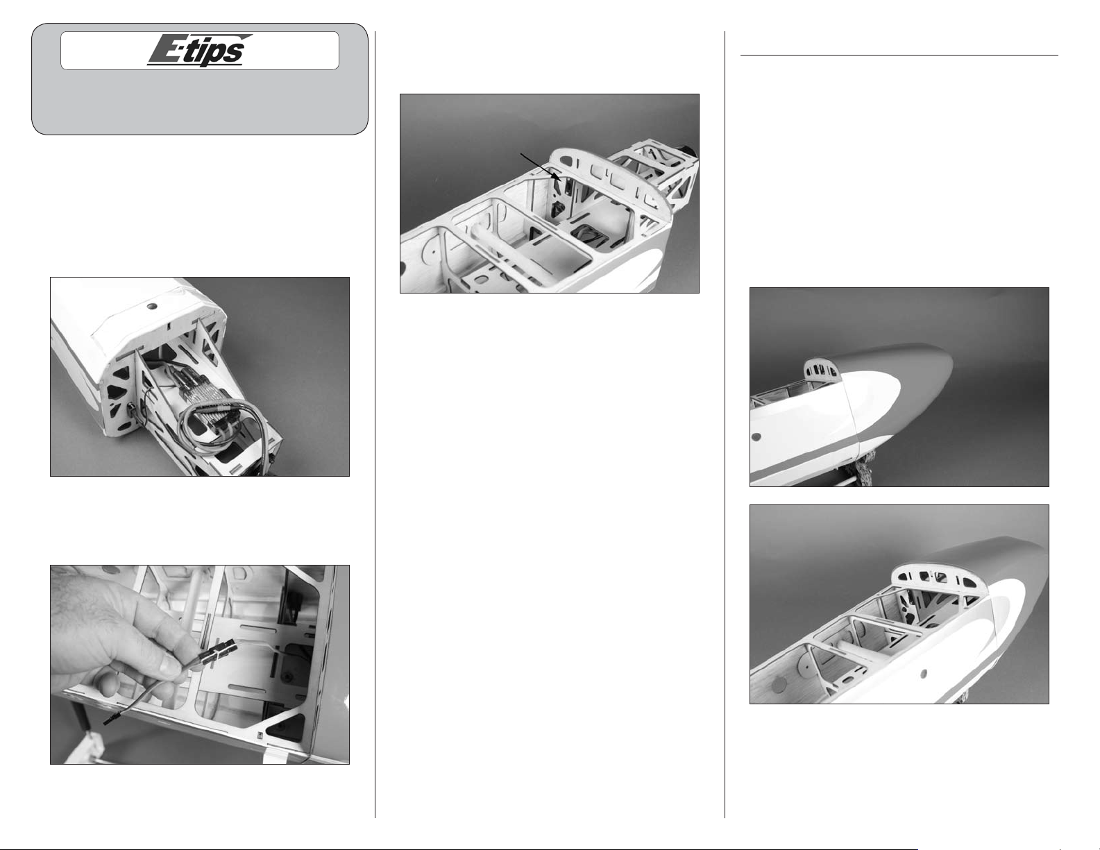
4. The speed control is mounted to the bottom
of the battery box using hook and loop tape.
Route the wires for the battery and servo
connection into the fuselage. Connect the leads
for the motor to those on the motor at this time.
Make sure these leads do not interfere with the
operation of the motor.
6. Mount the switch from the speed control to the
fuselage as shown. Use a #1 Phillips screwdriver to
tighten the screws that secure the switch.
Cowling and Spinner Installation
Required Parts
Fuselage assembly Spinner assembly
Cowling #4 washer (2)
Propeller
4-40 x 1-inch socket head screw (2)
Required Tools and Adhesives
Ball driver: 3/32-inch
Box wrench or open end wrench: 10mm
1. Fit the cowling to the fuselage. It should overlap
the fuselage as shown.
5. Secure a 3-inch (76mm) servo extension to
the lead from the speed control using string or a
commercially available connector.
10 E-flite Extra 300 32e ARF Assembly Manual
Page 11
2. The cowling is secured using two (2) 4-40 x
1-inch socket head screws and two (2) #4 washers.
You will need to use a ball driver to tighten these
screws. The ball driver will allow you to access the
screws at an angle so they can be tightened.
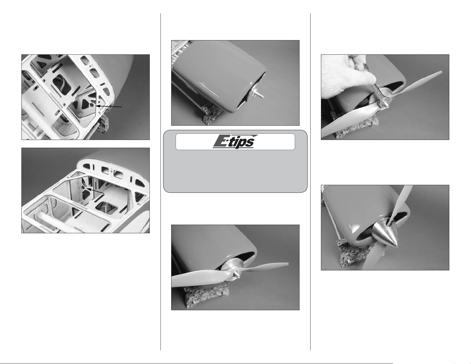
3. Slide the spinner adapter and backplate on the
motor. Leave a gap of 3/32-inch to 1/8-inch (2.5
to 3mm) between the cowl and backplate.
5. Slide the propeller washer on the adapter, then
thread the nut in position. Use a 10mm box wrench
or open end wrench to tighten the propeller nut.
Do not use pliers as pliers will eventually round the
corners of the nut.
Always a good idea to balance your propeller.
An unbalanced propeller can cause vibrations
to be transmitted into the airframe which could
damage the airframe or other components as well
as produce unwanted flight characteristics.
4. Slide the propeller on the adapter. It may be
necessary to enlarge the hole in the propeller so it
fits over the adapter.
6. Install the spinner cone. Position the spinner cone
so it doesn’t contact the propeller as shown. Secure
the spinner cone using the screw provided with the
spinner and a 3/32-inch hex wrench or ball driver.
11E-flite Extra 300 32e ARF Assembly Manual
Page 12

Landing Gear and Wheel Installation
Required Parts
Fuselage assembly Axle with hardware (2)
#4 washer (5) Aluminum landing gear
Main wheel (2) Wheel pant (left and right)
4-40 x 1-inch socket head screw (3)
4-40 x 3/8-inch socket head screw (2)
Required Tools and Adhesives
Hex wrench or ball driver: 1.5mm, 3/32-inch
Threadlock Nut driver: 7mm
Flat file Pliers or adjustable wrench
1. Remove the landing gear fairing from the
fuselage and set it aside.
2. Attach the landing gear using two (2) 4-40 x
1-inch socket head screws and two (2) #4 washers.
Use a 3/32-inch hex wrench or ball driver to
tighten the screws. Only install the outer screws
as shown in the photo. The center hole is for the
attachment of the landing gear fairing.
Always use threadlock on metal-to-metal fasteners
to prevent them from vibrating loose.
4. Attach the axle to the landing gear. Use a 7mm
nut driver to tighten the locknut while holding the
axle with an adjustable wrench or pliers.
5. Use a 1.5mm hex wrench to loosen the setscrew
in the wheel collar to remove the collar. Use a file
to make a flat area for the first 1/4-inch (6mm) on
the bottom of the axle. This will provide an area to
tighten the setscrew, making it more secure.
3. Use a 4-40 x 1-inch socket head screw and
#4 washer to attach the landing gear fairing to
the fuselage.
Always use threadlock on metal-to-metal fasteners
to prevent them from vibrating loose.
The landing gear can only be installed in one
direction. If the holes in the landing gear don’t
align with the blind nuts in the fuselage, rotate
the gear front-to-back so the holes are aligned
with the blind nuts installed in the fuselage.
12 E-flite Extra 300 32e ARF Assembly Manual
Always use threadlock on metal-to-metal fasteners
to prevent them from vibrating loose.
Page 13

6. Slide the wheel on the axle. Use a 1.5mm hex
wrench to tighten the wheel collar that secures the
wheel to the axle.
Always use threadlock on metal-to-metal fasteners
to prevent them from vibrating loose.
7. Slide the wheel pant over the wheel. Position
it so the hole in the landing gear aligns with the
blind nut in the wheel pant. Use a 4-40 x 3/8-inch
socket head screw and #4 washer to secure the
position of the wheel pant. Tighten the screw using
a 3/32-inch hex wrench or ball driver.
8. Repeat Steps 4 through 7 to install the remaining
wheel and wheel pant.
Fuselage Servo and
Receiver Installation
Required Parts
Fuselage assembly Hook and loop tape
Receiver Servo with accessories (2)
Servo extension, 18-inch (457mm)
Required Tools and Adhesives
Pencil String
Thin CA Phillips screwdriver: #1
Pin vise Drill bit: 1/16-inch (1.5mm)
1. Secure a 18-inch (457mm) servo extension to the
elevator servo lead using string or a commercially
available connector. This will keep the servo and
lead from disconnecting inside the fuselage.
Note: You should have already installed the grommets
earlier when you did the aileron servos. If you didn't,
please go back to page 6, Step 4 for instructions.
13E-flite Extra 300 32e ARF Assembly Manual
Page 14

2. Place the elevator servo in the fuselage with the
servo output to the rear. With the servo positioned
so it is not touching the sides of the opening, use
a pencil to transfer the locations for the four servo
mounting screws on the fuselage.
3. Move the servo from the fuselage. Use a pin vise
with a 1/16-inch (1.5mm) drill bit to drill the four
holes in the fuselage for the servo mounting screws.
4. Place 2–3 drops of thin CA in each of the holes
to harden the surrounding wood. This will help in
preventing the screws from vibrating loose.
5. Use the four (4) screws provided with the servo
and a #1 Phillips screwdriver to secure the servo in
the fuselage.
6. Repeat Steps 2 through 5 to install the rudder
servo in the fuselage.
7. Use hook and loop tape to install the main
receiver and remote receiver in the fuselage. Make
sure to plug the speed control, rudder and elevator
into the appropriate ports of the receiver at this time.
14 E-flite Extra 300 32e ARF Assembly Manual
Page 15

Stabilizer Installation
Required Parts
Fuselage assembly Heavy-duty servo horn
Elevator and stabilizer assembly
Required Tools and Adhesives
30-minute epoxy Hobby knife with #11 blade
Mixing cup Mixing stick
Epoxy brush Paper towel
Rubbing alcohol Felt-tipped pen
Pin vise Drill bit: 5/64-inch (2mm)
Side cutters Phillips screwdriver: #1
1. Disassemble the elevator and stabilizer assembly.
Make sure to place the parts nearby so they can be
used in the next two sections of the manual.
2. Use a #1 Phillips screwdriver to remove the
stock servo arm from the elevator servo. Install a
heavy-duty servo arm on the elevator servo so it
is perpendicular to the servo centerline. Use side
cutters to remove the arm that faces upward on the
servo so it doesn’t interfere with the operation of
the servo.
3. Use a pin vise with a 5/64-inch (2mm) drill bit
to enlarge the outer hole of the elevator servo arm.
4. Carefully remove the fin fairing from the
fuselage. Set the fin fairing aside at this time.
5. Slide the two carbon tubes into one of the
stabilizer halves.
15E-flite Extra 300 32e ARF Assembly Manual
Page 16

6. Slide the tubes into the holes at the rear of the
fuselage. The stabilizer will fit tight against the
fuselage. Use a felt-tipped pen to trace the outline
of the stabilizer on the fuselage.
9. Check the fit of both stabilizers to the fuselage.
They must fit tightly to the fuselage as shown. If not,
the stabilizer tubes will need to be shortened until
they both fit tight as shown.
8. Repeat Steps 5 through 7 to prepare the
opposite side of the fuselage.
Use caution when trimming the covering.
Accidentally cutting into the wood will weaken
the structure and may cause failure in flight.
7. Remove the stabilizer from the fuselage. Use
a hobby knife with a new #11 blade to trim the
covering 1/16-inch (1.5mm) inside the lines drawn
on the fuselage.
Read through the following steps to understand
them completely. These steps must be performed
before the epoxy begins to cure.
10. Remove the stabilizers from the fuselage as
well as the tubes from the stabilizer halves. Mix
1/4 ounce (15mL) of 30-minute epoxy. Apply a
small amount of epoxy in the holes of the stabilizer
for the stabilizer tubes.
16 E-flite Extra 300 32e ARF Assembly Manual
Page 17

11. Slide the stabilizer tubes in the stabilizer. Use
an epoxy brush to apply a thin layer of epoxy on
the root end of the stabilizer.
13. Slide the stabilizer into position. It must be
pressed tight against the fuselage. Use a paper towel
and rubbing alcohol to remove any excess epoxy.
15. Use an epoxy brush to apply a thin layer of
epoxy on the root end of the stabilizer. Also apply
epoxy to the exposed wood on the side of the
fuselage as described in Step 12.
12. Use an epoxy brush to apply a thin layer of
epoxy on the exposed wood of the fuselage at this
time as well.
14. Apply a small amount of epoxy in the holes
of the stabilizer for the stabilizer tubes in the
remaining stabilizer half.
16. Slide the remaining stabilizer into position. It
must be pressed tight against the fuselage. Use a
paper towel and rubbing alcohol to remove any
excess epoxy. Set the fuselage assembly aside until
the epoxy has fully cured.
17E-flite Extra 300 32e ARF Assembly Manual
Page 18

Elevator Installation
Required Parts
Fuselage assembly Control horn assembly
Nylon control horn Elevator joiner wire
CA hinge (6) Clevis
Clevis retainer Elevator (left and right)
Pushrod wire, 31/2-inch (90mm)
Plastic packaging from model
Required Tools and Adhesives
Scissors Medium grit sandpaper
Low-tack tape Thin CA
30-minute epoxy Toothpick
T-pins Hobby knife with #11 blade
Pin vise Drill bit: 1/16-inch (1.5mm)
Threadlock Phillips screwdriver: #2
Pliers Mixing cups
Paper towels Rubbing alcohol
Mixing sticks
1. Use medium grit sandpaper to lightly sand the
ends of the elevator joiner wire. This will provide a
surface for the epoxy to adhere to.
2. Cut two strips of the clear plastic film the model
was packaged in using scissors. Use low-tack tape
to tape the plastic to the elevators so the joiner wire
isn’t accidentally glued to the stabilizers.
3. Use a pin vise with a 1/16-inch (1.5mm) drill
bit to drill a hole in the center of each of the hinge
slots in both the elevators and stabilizers.
Always use threadlock on metal-to-metal fasteners
to prevent them from vibrating loose.
4. Remove the tapered nut and one countersink
from the control horn screw. Slide the screw and
remaining countersink into the hole in the elevator.
The screw must exit to the bottom of the elevator.
5. Slide the countersink back onto the control horn
screw. The tapered nut is then threaded on the
screw to secure its position on the elevator. Use
a #2 Phillips screwdriver and pliers to tighten the
hardware. Thread the nylon control horn onto the
control horn screw so it is flush with the end of the
screw as shown.
18 E-flite Extra 300 32e ARF Assembly Manual
Page 19

6. Slide the elevator joiner wire into position in the
slot at the rear of the fuselage.
4. Place a T-pin in the center of each of the hinges
as shown. You will need to prepare three (3) hinges
in this step.
5. Slide the three (3) hinges into the slots in the
elevator. The T-pins will center the hinges so an
equal amount of hinge is in both the elevator
and stabilizer.
6. Test fit the elevator into position using the hinges.
Make sure the elevator joiner wire is positioned in
the elevator as well. The elevator should fit tightly
against the stabilizer in this step. If it does not,
check to determine why and correct as necessary.
Read through the following steps to understand
them completely. These steps must be performed
before the epoxy begins to cure.
8. Mix 1/4 ounce (15mL) of 30-minute epoxy. Use
a mixing stick to apply the epoxy to the elevator
joiner wire where it fits into the elevator.
7. Repeat Steps 4 through 6 to check the fit of the
remaining elevator half to the stabilizer.
9. Use a toothpick to apply epoxy to the hole in the
elevator for the joiner wire.
10. Repeat Steps 8 and 9 to apply the epoxy for
the remaining elevator half.
19E-flite Extra 300 32e ARF Assembly Manual
Page 20

11. Fit the elevator halves to the stabilizer. Remove
the T-pins from the hinges. Position the elevators
so the tips of the elevators align with the tips of the
stabilizers. Set the hinge gap using a hobby knife
and #11 blade. The blade should just fit into the
gap between the elevator and stabilizer as shown.
When hinging the elevators, do not use CA accelerator.
The CA must be allowed to penetrate the hinge or
the bond between the hinge and wood could fail.
13. Once the CA has cured, gently pull on the
elevator and stabilizer to check that the hinges are
secure. If any hinges are not secure, apply more
CA and recheck them once the CA cures.
14. Flex the elevator through its range of motion a
number of times to break in the hinges.
15. Slide a clevis retainer on a nylon clevis. Thread
the clevis onto the 31/2-inch (90mm) linkage wire.
Insert the bend in the linkage in the hole enlarged
in the elevator servo arm. Adjust the clevis so
when it is attached to the elevator control horn the
elevator is centered.
12. Flex the elevators slightly so the hinges can be
accessed. Use care not to change the hinge gap.
Saturate each hinge with thin CA on both the top
and bottom of the hinge. Allow the CA to fully cure
before proceeding.
20 E-flite Extra 300 32e ARF Assembly Manual
Page 21

Fin Installation
Check that both angles are equal
Required Parts
Fuselage assembly Fin fairing
Rudder and fin assembly
Required Tools and Adhesives
Ruler Low-tack tape
Square 30-minute epoxy
Rubbing alcohol Paper towels
Mixing stick Mixing cup
1. Separate the rudder from the vertical fin. Set the
rudder and hinges aside at this time.
3. Check the alignment of the fin to the
stabilizer. Since both the fin and stabilizer are
tapered, you won’t be able to use a square to
accurately set the angles during this step, but it
will help gauge the angles.
4. Once the alignment has been checked, mix 1/4
ounce (15mL) of 30-minute epoxy and apply it to
the bottom of the fin where is contacts the fuselage.
Use low-tack tape to hold the fin in alignment
until the epoxy fully cures. Use a paper towel and
rubbing alcohol to remove any excess epoxy before
it has a chance to cure.
5. Once the epoxy has cured between the fin and
fuselage you can install the fin fairing. Use 30-minute
epoxy to glue the fairing in position. Use low-tack
tape to hold it in place until the epoxy cures. Use
a paper towel and rubbing alcohol to remove any
excess epoxy before it has a chance to cure.
2. Place the fin on the fuselage. Use a ruler to
align the rear edge of the fin to the rear edge of
the fuselage.
21E-flite Extra 300 32e ARF Assembly Manual
Page 22

Rudder and Tail Wheel Installation
Required Parts
Fuselage assembly Rudder
CA hinge (2) Rudder control horn screw
Tail wheel assembly Nylon control horn (2)
Tail wheel Wheel collar with setscrew
Required Tools and Adhesives
Low-tack tape Medium grit sandpaper
Pin vise Drill bit: 1/16-inch (1.5mm)
Petroleum jelly 30-minute epoxy
Thin CA T-pins
Toothpick Hobby knife with #11 blade
Pliers (2) Hex wrench: 1.5mm
Mixing cups Mixing sticks
Rubbing alcohol Paper towels
Ruler Threadlock
1. Apply a small amount of Petroleum jelly using
a toothpick at the top and bottom of the tail gear
bushing. Work the jelly into the bushing to prevent
epoxy from entering the bushing. If epoxy enters, it
could glue the wire to the bushing.
2. Use medium grit sandpaper to roughen the
section of the wire that will enter the rudder. This
provides a surface for the epoxy to adhere to.
Always use threadlock on metal-to-metal fasteners
to prevent them from vibrating loose.
4. Insert the rudder control screw through the
rudder. Position the screw equally on both sides
of the rudder. Use two pair of pliers to tighten the
tapered nuts to secure the screw.
3. Apply 30-minute epoxy to the bushing where
it fits into the fuselage. Insert the bushing in
the fuselage and use low-tack tape to hold the
assembly in position until the epoxy fully cures.
22 E-flite Extra 300 32e ARF Assembly Manual
Page 23

5. Thread a nylon control horn on each end of
the threaded rod. Position the horns so they are
flush with the ends of the rod. Also make sure the
distance from the rudder surface to the control horn
is equal on both sides.
6. Use a pin vise with a 1/16-inch (1.5mm) drill bit
to drill a hole in the center of the two hinge slots in
the rudder and fin.
8. Slide the two (2) hinges into the slots in the
rudder. The T-pins will center the hinges so an equal
amount of hinge is in both the rudder and fin.
9. Test fit the rudder into position using the hinges.
Make sure the tail gear wire is positioned in the
rudder as well. The rudder should fit tightly against
the stabilizer in this step. If it does not, check to
determine why and correct as necessary.
7. Place a T-pin in the center of each of the hinges
as shown. You will need to prepare two (2) hinges
in this step.
23E-flite Extra 300 32e ARF Assembly Manual
Page 24

10. Mix a small amount of epoxy. Use a toothpick
to insert the epoxy in the hole in the rudder where
the wire fits into. Also apply a small amount of
epoxy to the wire itself.
11. Reposition the rudder to the fin. Remove the
T-pins from the hinges and check the gap between the
rudder and fin using a hobby knife and #11 blade.
Use a paper towel and alcohol to clean and epoxy
that squeezes out.
14. Flex the rudder through its range of motion a
number of times to break in the hinges.
When hinging the rudder, do not use CA accelerator.
The CA must be allowed to penetrate the hinge or
the bond between the hinge and wood could fail.
12. Move the rudder slightly to access the hinges
without changing the hinge gap. Saturate each
hinge on both sides with thin CA. Allow the CA to
fully cure before proceeding.
13. Once the CA has cured, gently pull on the
rudder and fin to check that the hinges are secure.
If any hinges are not secure, apply more CA and
recheck them once the CA cures.
15. Attach the tail wheel to the tail wheel wire
using a wheel collar and 1.5mm hex wrench. Make
sure to use threadlock on the setscrew to prevent it
from vibrating loose.
24 E-flite Extra 300 32e ARF Assembly Manual
Page 25

Rudder Pull-Pull Cable Installation
Required Parts
Fuselage assembly Rudder cable (2)
Cable fitting (4) Cable crimp (4)
Nylon clevis (4) Clevis retainer (4)
Radio system Heavy-duty servo horn
Required Tools and Adhesives
Low-tack tape Crimping tool or pliers
Side cutters Hobby knife with #11 blade
Phillips screwdriver: #1
1. Using low-tack tape to keep the rudder centered
when installing the rudder cables will make the
installation much easier.
3. The cable then goes through the hole in the
cable fitting as shown.
4. Pass the cable back through the crimp, then loop
the cable through the crimp again.
6. Use a hobby knife with a #11 blade to
remove the covering from the fuselage for the
cable to pass through.
7. Insert the end of the rudder cable with the
fitting into the fuselage through the hole in the
side of the fuselage.
2. Slide a crimp on one end of a rudder cable.
5. Use a crimping tool or pliers to secure the crimp
to the cable.
25E-flite Extra 300 32e ARF Assembly Manual
Page 26

8. Use low-tack tape to keep the cable from
accidentally falling into the fuselage.
9. Slide a clevis retainer on a nylon clevis. Hold the
cable fitting with pliers to thread the clevis on the
fitting. The end of the fitting should just be visible
between the forks of the clevis.
11. Check that the cable is not tangled in any of
the formers or the elevator servo wires. It must be
a straight shot to the rudder servo. The cable will
connect to the servo arm on the opposite side as
the rudder control horn.
12. Repeat Steps 2 through 11 (excluding Step 10)
to run the remaining rudder cable. Note that the
cables cross inside the fuselage.
13. Slide a clevis retainer on a nylon clevis. Hold
the cable fitting with pliers while threading the
clevis on the fitting. Thread the clevis on far enough
so the threads of the fitting are almost visible
between the forks of the clevis.
14. Attach the clevis to the rudder control horn.
10. Remove the stock servo horn from the rudder
servo using a #1 Phillips screwdriver. Install
a heavy-duty servo horn on the servo so it is
perpendicular to the rudder servo centerline.
26 E-flite Extra 300 32e ARF Assembly Manual
Page 27

15. Slide a crimp on the end of the cable outside
the fuselage. The cable then can pass through
the hole in the cable fitting then back through the
crimp. Do not use crimping pliers at this time.
16. Repeat Steps 13 through 15 for the opposite
cable. Remove the tape from the fuselage at this
time as well.
When setting the rudder cables it is best to have the
radio system on to keep the rudder servo centered.
17. Adjust the cable in the crimps so there is light
tension on each of the cables. Once tensioned, use
crimping pliers to secure the crimps to the cables.
Use side cutters to trim any excess wire that could
interfere with the operation of the rudder.
Check the tension of the cables periodically to make
sure they are not slack. If so, adjust the clevises on
both sides to reset the tension on the wires or you may
have difficulty keeping the rudder correctly trimmed.
18. You may now remove the low-tack tape that is
holding the rudder straight.
19. Now re-tension the cables to ensure the
rudder moves freely and holds center with the
radio system on.
27E-flite Extra 300 32e ARF Assembly Manual
Page 28

Wing Installation
Required Parts
Fuselage assembly Wing panel (right and left)
Carbon wing tube #4 washer (2)
4-40 x 1-inch socket head screw (2)
Required Tools and Adhesives
Ball driver: 3/32-inch
1. Slide the carbon wing tube in one of the wing
panels. It will only fit in so far, so only slide it in as
far as it will easily slide.
3. Slide the wing tightly against the fuselage. The
rear anti-rotation pin will fit into the fuselage to
keep the wing from rotating.
4. Use a 4-40 x 1-inch socket head screw and #4
washer to secure the wing to the fuselage. Use a
ball driver to tighten the screw. Use of a ball driver
is highly suggested as the screw can not be easily
accessed directly with a standard hex wrench.
5. Repeat Steps 2 through 4 to attach the
remaining wing panel to the fuselage.
6. Plug the aileron servos into the correct ports of
the receiver.
2. Slide the tube into the fuselage. Make sure to
guide the servo lead from the aileron servo into the
fuselage as well.
28 E-flite Extra 300 32e ARF Assembly Manual
Page 29

Battery Installation
Required Parts
Motor battery Fuselage assembly
Hook and loop strap
1. Use a hook and loop strap (not included) to
secure the battery in the fuselage. The location of
the battery can be adjusted if necessary to achieve
the correct Center of Gravity.
Canopy Installation
Required Parts
Fuselage assembly Canopy hatch
Canopy Pilot (modelers choice)
Required Tools and Adhesives
Canopy glue Medium grit sandpaper
Felt-tipped pen Clear paper or waxed paper
Low-tack tape Paper towels
Rubbing alcohol
1. Place a piece of the clear plastic your model
was packed in or a piece of waxed paper over
the fuselage in the area of the canopy hatch. This
will keep you from accidentally gluing the hatch
to the fuselage.
3. Place the canopy on the fuselage. Use a felt-
tipped pen to trace the outline of the canopy on the
canopy hatch. Make sure to center the canopy on
the model before making any marks.
4. Use medium grit sandpaper to lightly sand
the canopy hatch 1/4-inch (6mm) inside the line
drawn in the previous step.
2. Install the canopy hatch on the fuselage. It may
be necessary to make adjustments to the plastic
or waxed paper to get the hatch pin to lock the
position of the hatch.
5. You may install a pilot of your choice at this time.
29E-flite Extra 300 32e ARF Assembly Manual
Page 30

6. Lightly sand the inside edge of the canopy at this
time as well. Use care not to over-sand the edge
and get into the clear area of the canopy.
7. Use canopy glue to glue the canopy to the
canopy hatch. Use low-tack tape to keep the
canopy in position until the glue has fully cured.
Center of Gravity
An important part of preparing the aircraft for flight is
properly balancing the model.
Caution: Do not inadvertently skip this step!
The recommended Center of Gravity (CG) location for
your model is 3
from the leading edge of the wing as shown with the
battery pack installed. Mark the location of the CG on
the top of the wing with a felt-tipped pen.
When balancing your model, support the plane
inverted at the marks made on the wing with your
fingers or a commercially available balancing stand.
This is the correct balance point for your model.
Adjust the motor battery as necessary so the model is
level or slightly nose down. This is the correct balance
point for your model. You should find the CG to be
very close with the battery installed forward in the
battery area inside the cowling.
1
/2 to 37/8 inches (90 to 98mm) back
After the first flights, the CG position can be adjusted
for your personal preference.
Control Throws
1. Turn on the transmitter and receiver of your
Extra 300 32e. Check the movement of the rudder
using the transmitter. When the stick is moved right,
the rudder should also move right. Reverse the
direction of the servo at the transmitter if necessary.
8. Remove the lines made by the felt-tipped
pen from the fuselage using paper towels and
rubbing alcohol.
We suggest a Center of Gravity of 31/2 for precision
flight and 37/8 for 3D flight. Some have found the CG
range to be a bit broader and is a personal taste and
feel. You may explore the range and find the location
that works best for you.
2. Check the movement of the elevator with the
radio system. Moving the elevator stick toward the
bottom of the transmitter will make the airplane
elevator move up.
3. Check the movement of the ailerons with the
radio system. Moving the aileron stick right will
make the right aileron move up and the left aileron
move down.
4. Use a ruler to adjust the throw of the elevator,
ailerons and rudder. Adjust the position of
the pushrod at the control horn to achieve the
following measurements when moving the sticks to
their endpoints.
30 E-flite Extra 300 32e ARF Assembly Manual
Page 31

Elevator High Rate
Up 21/4-inch (57mm)
Down 21/4-inch (57mm)
Elevator Low Rate
Up 3/4-inch (19mm)
Down 3/4-inch (19mm)
Aileron High Rate
Up 2-inch (51mm)
Down 2-inch (51mm)
Aileron Low Rate
Up 5/8-inch (16mm)
Down 5/8-inch (16mm)
Rudder High Rate
Right 3-inch (76mm)
Left 3-inch (76mm)
Rudder Low Rate
Right 1
Left 11/2-inch (38mm)
1
/2-inch (38mm)
Preflight
Check Your Radio
Before going to the field, be sure that your batteries
are fully charged per the instructions included with
your radio. Charge the transmitter and motor battery
for your airplane. Use the recommended charger
supplied with your particular radio system, following
the instructions provided with the radio. In most
cases, the radio should be charged the night before
going out flying.
Before each flying session, be sure to range check your
radio. See your radio manual for the recommended
range and instructions for your radio system. Each
radio manufacturer specifies different procedures for
their radio systems. Next, run the motor. With the
model securely anchored, check the range again.
The range test should not be significantly affected. If
it is, don’t attempt to fly! Have your radio equipment
checked out by the manufacturer.
Keep loose items that can get entangled in
the propeller away from the prop. These
include loose clothing, or other objects such
as pencils and screwdrivers. Especially keep
your hands away from the propeller.
Flying Your Extra 300 32e ARF
The Extra 300 32e has been designed to meet the
current IMAC rules regarding changing of the airframe
outline. The deviation is no more than 10% in any area
and meets all IMAC regulations. You will find the Extra
300 performs precision maneuvers with a very tight
feel through the entire flight envelope. Takeoffs are as
easy as applying the power and a slight amount of
right rudder correction to lift off. Vertical performance
is very strong and predictable. The Extra can perform
any aerobatic maneuver you request. Landings are a
breeze, and just line up on final approach and adjust
your power to touch down. We hope you enjoy flying
your Extra 300 and appreciate its aerobatic prowess
as much as we do.
Happy landings.
Range Test Your Radio
Before each flying session, and especially with a new
model, it is important to perform a range check. It
is helpful to have another person available to assist
during the range check. If you are using a Spektrum
transmitter, please refer to your transmitter’s manual for
detailed instructions on the range check process.
1. With the model resting on the ground, stand 30
paces (approximately 90 feet) away from the model.
Measurements are taken at the inner or
widest point on the control surface.
These are general guidelines measured from our own
flight tests. You can experiment with higher rates to
match your preferred style of flying.
Travel Adjust, Sub-Trim and Dual Rates are
not listed and should be adjusted according
to each individual model and preference.
Double-check that all controls (aileron, elevator, rudder
and throttle) move in the correct direction.
Check the radio installation and make sure all the
control surfaces are moving correctly (i.e., the correct
direction and with the recommended throws).
Check all the control horns, servo horns, and clevises
to make sure they are secure and in good condition.
2. Face the model with the transmitter in your
normal flying position. Be sure the throttle is in the
full down position and plug the flight battery into
the speed control.
3. As you move the controls, watch to be sure the
airplane’s motor and controls operate smoothly.
You should have total control of the model at 30
paces (90 feet).
4. If control issues exist, call the Horizon Support
Team at 1 877 504 0233 or go to horizonhobby.
com to find a local Spektrum distributor in your
country for service if you are using a Spektrum
radio system.
31E-flite Extra 300 32e ARF Assembly Manual
Page 32

Safety Do’s and Don’ts for Pilots
Daily Flight Checks
Warranty Information
• Checkallcontrolsurfacespriortoeachtakeoff.
• Donotflyyourmodelnearspectators,parking
areas or any other area that could result in injury to
people or damage of property.
• Donotflyduringadverseweatherconditions.Poor
visibility can cause disorientation and loss of control
of your aircraft. Strong winds can cause similar
problems.
• Donottakechances.Ifatanytimeduringflightyou
observe any erratic or abnormal operation, land
immediately and do not resume flight until the cause
of the problem has been ascertained and corrected.
Safety can never be taken lightly.
• Donotflynearpowerlines.
1. Check the battery voltage of the transmitter
battery. Do not fly below the manufacturer’s
recommended voltage. To do so can crash
your aircraft.
When you check these batteries, ensure that you have
the polarities correct on your expanded scale voltmeter.
2. Check all hardware (linkages, screws, nuts,
and bolts) prior to each day’s flight. Be sure that
binding does not occur and that all parts are
properly secured.
3. Ensure that all surfaces are moving in the
proper manner.
4. Perform a ground range check before each
day’s flying session.
5. Prior to starting your aircraft, turn off your
transmitter, then turn it back on. Do this each time
you start your aircraft. If any critical switches are
on without your knowledge, the transmitter alarm
will sound a warning at this time.
6. Check that all trim levers are in the
proper location.
7. All servo pigtails and switch harness plugs
should be secured in the receiver. Make sure that
the switch harness moves freely in both directions.
WARRANTY PERIOD
Exclusive Warranty- Horizon Hobby, Inc., (Horizon)
warranties that the Products purchased (the “Product”)
will be free from defects in materials and workmanship
at the date of purchase by the Purchaser.
LIMITED WARRANTY
Horizon reserves the right to change or modify this
warranty without notice and disclaims all other
warranties, express or implied.
(a) This warranty is limited to the original Purchaser
(“Purchaser”) and is not transferable. REPAIR OR
REPLACEMENT AS PROVIDED UNDER THIS WARRANTY
IS THE EXCLUSIVE REMEDY OF THE PURCHASER. This
warranty covers only those Products purchased from an
authorized Horizon dealer. Third party transactions are
not covered by this warranty. Proof of purchase is required
for warranty claims. Further, Horizon reserves the right
to change or modify this warranty without notice and
disclaims all other warranties, express or implied.
(b) Limitations- HORIZON MAKES NO WARRANTY
OR REPRESENTATION, EXPRESS OR IMPLIED, ABOUT
NON-INFRINGEMENT, MERCHANTABILITY OR FITNESS
FOR A PARTICULAR PURPOSE OF THE PRODUCT. THE
PURCHASER ACKNOWLEDGES THAT THEY ALONE
HAVE DETERMINED THAT THE PRODUCT WILL SUITABLY
MEET THE REQUIREMENTS OF THE PURCHASER’S
INTENDED USE.
(c) Purchaser Remedy- Horizon’s sole obligation hereunder
shall be that Horizon will, at its option, (i) repair or
(ii) replace, any Product determined by Horizon to be
defective. In the event of a defect, these are the Purchaser’s
exclusive remedies. Horizon reserves the right to inspect
any and all equipment involved in a warranty claim.
Repair or replacement decisions are at the sole discretion
of Horizon. This warranty does not cover cosmetic damage
or damage due to acts of God, accident, misuse, abuse,
negligence, commercial use, or modification of or to any
part of the Product. This warranty does not cover damage
due to improper installation, operation, maintenance, or
attempted repair by anyone other than Horizon. Return of
any goods by Purchaser must be approved in writing by
Horizon before shipment.
32 E-flite Extra 300 32e ARF Assembly Manual
Page 33

DAMAGE LIMITS
QUESTIONS, ASSISTANCE, AND REPAIRS
NON-WARRANTY REPAIRS
HORIZON SHALL NOT BE LIABLE FOR SPECIAL,
INDIRECT OR CONSEQUENTIAL DAMAGES, LOSS
OF PROFITS OR PRODUCTION OR COMMERCIAL
LOSS IN ANY WAY CONNECTED WITH THE
PRODUCT, WHETHER SUCH CLAIM IS BASED IN
CONTRACT, WARRANTY, NEGLIGENCE, OR STRICT
LIABILITY. Further, in no event shall the liability of
Horizon exceed the individual price of the Product on
which liability is asserted. As Horizon has no control
over use, setup, final assembly, modification or misuse,
no liability shall be assumed nor accepted for any
resulting damage or injury. By the act of use, setup or
assembly, the user accepts all resulting liability.
If you as the Purchaser or user are not prepared
to accept the liability associated with the use of
this Product, you are advised to return this Product
immediately in new and unused condition to the place
of purchase.
Law: These Terms are governed by Illinois law (without
regard to conflict of law principals).
SAFETY PRECAUTIONS
This is a sophisticated hobby Product and not a toy.
It must be operated with caution and common sense
and requires some basic mechanical ability. Failure to
operate this Product in a safe and responsible manner
could result in injury or damage to the Product or
other property. This Product is not intended for use by
children without direct adult supervision. The Product
manual contains instructions for safety, operation and
maintenance. It is essential to read and follow all
the instructions and warnings in the manual, prior to
assembly, setup or use, in order to operate correctly
and avoid damage or injury.
Your local hobby store and/or place of purchase
cannot provide warranty support or repair. Once
assembly, setup or use of the Product has been
started, you must contact Horizon directly. This will
enable Horizon to better answer your questions
and service you in the event that you may need any
assistance. For questions or assistance, please direct
your email to productsupport@horizonhobby.com,
or call 877.504.0233 toll free to speak to a service
technician.
INSPECTION OR REPAIRS
If this Product needs to be inspected or repaired,
please call for a Return Merchandise Authorization
(RMA). Pack the Product securely using a shipping
carton. Please note that original boxes may be
included, but are not designed to withstand the rigors
of shipping without additional protection. Ship via a
carrier that provides tracking and insurance for lost
or damaged parcels, as Horizon is not responsible
for merchandise until it arrives and is accepted at our
facility. A Service Repair Request is available at www.
horizonhobby.com on the “Support” tab. If you do
not have internet access, please include a letter with
your complete name, street address, email address
and phone number where you can be reached during
business days, your RMA number, a list of the included
items, method of payment for any non-warranty
expenses and a brief summary of the problem.
Your original sales receipt must also be included for
warranty consideration. Be sure your name, address,
and RMA number are clearly written on the outside of
the shipping carton.
WARRANTY INSPECTION AND REPAIRS
To receive warranty service, you must include your
original sales receipt verifying the proof-of-purchase
date. Provided warranty conditions have been met,
your Product will be repaired or replaced free of
charge. Repair or replacement decisions are at the sole
discretion of Horizon Hobby.
Should your repair not be covered by warranty the
repair will be completed and payment will be required
without notification or estimate of the expense unless
the expense exceeds 50% of the retail purchase cost.
By submitting the item for repair you are agreeing
to payment of the repair without notification. Repair
estimates are available upon request. You must include
this request with your repair. Non-warranty repair
estimates will be billed a minimum of 1/2 hour of
labor. In addition you will be billed for return freight.
Please advise us of your preferred method of payment.
Horizon accepts money orders and cashiers checks,
as well as Visa, MasterCard, American Express, and
Discover cards. If you choose to pay by credit card,
please include your credit card number and expiration
date. Any repair left unpaid or unclaimed after 90
days will be considered abandoned and will be
disposed of accordingly. Please note: non-warranty
repair is only available on electronics and model
engines.
United States:
Electronics and engines requiring inspection or repair
should be shipped to the following address:
Horizon Service Center
4105 Fieldstone Road
Champaign, Illinois 61822
USA
All other Products requiring warranty inspection or
repair should be shipped to the following address:
Horizon Product Support
4105 Fieldstone Road
Champaign, Illinois 61822
USA
Please call 877-504-0233 or e-mail us at
productsupport@horizonhobby.com with any questions
or concerns regarding this product or warranty.
33E-flite Extra 300 32e ARF Assembly Manual
Page 34

United Kingdom:
Electronics and engines requiring inspection or repair
should be shipped to the following address:
Horizon Hobby UK
Units 1-4 Ployters Rd
Staple Tye
Harlow, Essex
CM18 7NS
United Kingdom
Please call +44 (0) 1279 641 097 or e-mail us at
sales@horizonhobby.co.uk with any questions or
concerns regarding this product or warranty.
Germany:
Electronics and engines requiring inspection or repair
should be shipped to the following address:
Horizon Technischer Service
Hamburger Strasse 10
25335 Elmshorn
Germany
Please call +49 4121 46199 66 or e-mail us at
service@horizonhobby.de with any questions or
concerns regarding this product or warranty.
Compliance Information for the
European Union
INSTRUCTIONS FOR DISPOSAL OF WEEE BY USERS IN
THE EUROPEAN UNION
This product must not be disposed of with other waste.
Instead, it is the user’s responsibility to dispose of their
waste equipment by handing it over to a designated
collection point for the recycling of waste electrical
and electronic equipment. The separate collection
and recycling of your waste equipment at the time
of disposal will help to conserve natural resources
and ensure that it is recycled in a manner that
protects human health and the environment. For more
information about where you can drop off your waste
equipment for recycling, please contact your local city
office, your household waste disposal service or where
you purchased the product.
Age Recommendation: 14 years or over. Not a toy.
Not intended for use by children without direct adult
supervision.
2009 Official Academy of Model
Aeronautics Safety Code
GENERAL
1. A model aircraft shall be defined as a non-humancarrying device capable of sustained flight in
the atmosphere. It shall not exceed limitations
established in this code and is intended to be used
exclusively for recreational or competition activity.
2. The maximum takeoff weight of a model aircraft,
including fuel, is 55 pounds, except for those flown
under the AMA Experimental Aircraft Rules.
3. I will abide by this Safety Code and all rules
established for the flying site I use. I will not
willfully fly my model aircraft in a reckless and/or
dangerous manner.
4. I will not fly my model aircraft in sanctioned events,
air shows, or model demonstrations until it has
been proven airworthy.
5. I will not fly my model aircraft higher than
approximately 400 feet above ground level, when
within three (3) miles of an airport without notifying
the airport operator. I will yield the right-of-way
and avoid flying in the proximity of full-scale
aircraft, utilizing a spotter when appropriate.
6. I will not fly my model aircraft unless it is identified
with my name and address, or AMA number,
inside or affixed to the outside of the model
aircraft. This does not apply to model aircraft flown
indoors.
7. I will not operate model aircraft with metal-blade
propellers or with gaseous boosts (other than
air), nor will I operate model aircraft with fuels
containing tetranitromethane or hydrazine.
34 E-flite Extra 300 32e ARF Assembly Manual
Page 35

8. I will not operate model aircraft carrying
pyrotechnic devices which explode burn, or propel
a projectile of any kind. Exceptions include Free
Flight fuses or devices that burn producing smoke
and are securely attached to the model aircraft
during flight. Rocket motors up to a G-series
size may be used, provided they remain firmly
attached to the model aircraft during flight. Model
rockets may be flown in accordance with the
National Model Rocketry Safety Code; however,
they may not be launched from model aircraft.
Officially designated AMA Air Show Teams (AST)
are authorized to use devices and practices as
defined within the Air Show Advisory Committee
Document.
9. I will not operate my model aircraft while under
the influence of alcohol or within eight (8) hours of
having consumed alcohol.
3. I will not fly my model aircraft in the presence of
spectators until I become a proficient flier, unless I
am assisted by an experienced pilot.
4. At all flying sites a line must be established,
in front of which all flying takes place. Only
personnel associated with flying the model aircraft
are allowed at or in front of the line. In the case
of airshows demonstrations straight line must be
established. An area away from the line must be
maintained for spectators. Intentional flying behind
the line is prohibited.
5. I will operate my model aircraft using only
radio-control frequencies currently allowed by
the Federal Communications Commission (FCC).
Only individuals properly licensed by the FCC are
authorized to operate equipment on Amateur Band
frequencies.
8. Under no circumstances may a pilot or other
person touch a model aircraft in flight while it is
still under power, except to divert it from striking an
individual.
9. Radio-controlled night flying is limited to lowperformance model aircraft (less than 100 mph).
The model aircraft must be equipped with a lighting
system which clearly defines the aircraft’s attitude
and direction at all times.
10. The operator of a radio-controlled model aircraft
shall control it during the entire flight, maintaining
visual contact without enhancement other than by
corrective lenses that are prescribed for the pilot.
No model aircraft shall be equipped with devices
which allow it to be flown to a selected location
which is beyond the visual range of the pilot.
Extra 300 32e Safe Operating Recommendations
10. I will not operate my model aircraft while using
any drug which could adversely affect my ability to
safely control my model aircraft.
11. Children under six (6) years old are only allowed
on a flightline or in a flight area as a pilot or while
under flight instruction.
12. When and where required by rule, helmets must be
properly worn and fastened. They must be OSHA,
DOT, ANSI, SNELL or NOCSAE approved or
comply with comparable standards.
RADIO CONTROL
1. All model flying shall be conducted in a manner to
avoid over flight of unprotected people.
2. I will have completed a successful radio equipment
ground-range check before the first flight of a new
or repaired model aircraft.
6. I will not knowingly operate my model aircraft
within three (3) miles of any preexisting flying site
without a frequency-management agreement. A
frequency management agreement may be an
allocation of frequencies for each site, a dayuse agreement between sites, or testing which
determines that no interference exists. A frequencymanagement agreement may exist between two
or more AMA chartered clubs, AMA clubs and
individual AMA members, or individual AMA
members. Frequency-management agreements,
including an interference test report if the
agreement indicates no interference exists, will be
signed by all parties and copies provided to AMA
Headquarters.
7. With the exception of events flown under official
AMA rules, no powered model may be flown
outdoors closer than 25 feet to any individual,
except for the pilot and located at the flightline.
- Inspect your model before every flight to make
certain it is airworthy.
- Be aware of any other radio frequency user who
may present an interference problem.
- Always be courteous and respectful of other
users of your selected flight area.
- Choose an area clear of obstacles and large
enough to safely accommodate your flying
activity.
- Make certain this area is clear of friends and
spectators prior to launching your aircraft.
- Be aware of other activities in the vicinity of your
flight path that could cause potential conflict.
- Carefully plan your flight path prior to launch.
- Abide by any and all established AMA National
Model Aircraft Safety Code.
35E-flite Extra 300 32e ARF Assembly Manual
Page 36

Horizon Hobby USA
4105 Fieldstone Road
Champaign, Illinois 61822
USA
(877) 504-0233
Horizon Hobby UK
Units 1-4 Ployters Rd
Staple Tye
Harlow, Essex
CM18 7NS
Horizon Hobby Deutschland GmbH
Hamburger Strasse 10
25335 Elmshorn
Germany
+49 4121 46199 60
United Kingdom
+44 (0) 1279 641 097
© 2010 Horizon Hobby, Inc.
horizonhobby.com
www.e-fliterc.com
16385 Printed 01/2010
 Loading...