

Page 1
Extra 260 3D Profile
Assembly Manual
Page 2

Table of Contents
Introduction ................................................................3
Specifications .............................................................3
Using the Manual
Contents of Kit/Parts Layout
Outrunner Setup
Variable Prop Outrunner Setup
Optional Accessories
Required Radio Equipment
Warning ....................................................................6
Required Tools and Adhesives
Note on Lithium Polymer Batteries
Limited Warranty Period
Limited Warranty & Limits of Liability
Safety Precautions
Questions, Assistance, and Repairs
Questions or Assistance
Inspection or Repairs
.......................................................3
.........................................4
.........................................................4
.....................................4
..................................................4
...........................................5
......................................6
.................................7
..............................................7
.............................8
.......................................................9
...............................9
...............................................9
...................................................9
Warranty Inspection and Repairs ................................10
Non-Warranty Repairs
Safety, Precautions, and Warnings
Airframe Assembly
Installing the Bracing
Radio Installation
Motor and Battery Installation
Landing Gear Installation
Control Throws
Center of Gravity
Range Testing the Radio
Preflight ...................................................................40
Notes ......................................................................41
2006 Official AMA
National Model Aircraft Safety Code
...............................................10
..............................11
....................................................12
.................................................17
......................................................22
....................................28
...........................................35
.........................................................38
......................................................39
............................................39
..........................42
2
Page 3

Introduction
Specifications
The Extra 260 3D Profile was designed by Aerodynamicist
and E-TOC champ George Hicks to give profile 3D foamie
fans a great-looking, lightweight plane with competitionlevel performance. At the heart of its superb flight
characteristics is a rigid, carbon reinforced Depron foam
airframe. This unique design eliminates flex so control
response is crisp and precise.
The Extra 260 is constructed from 3mm laser-cut Depron
foam—the standard for durability and quality for pro 3D
foamie pilots everywhere. All pieces come with a sharplooking factory-applied color scheme.
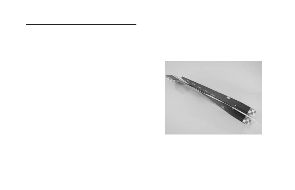
Carbon Rod Reinforcement
Much of the Extra 260’s exceptional flight performance
comes from its carbon-reinforced airframe that eliminates
flex so control response is crisp and precise. The leading
and trailing edges of the wing come out of the box with
factory-applied carbon strips. Carbon rods are also
included that further strengthen the fuselage and tail.
Visit our web site at www.horizonhobby.com or
www.E-fliteRC.com for George Hicks’ flying tips.
Wingspan: 32.5 in (825mm)
Length: 33 in (840mm)
Wing Area: 260 sq in (16.8 sq dm)
Weight w/o Battery: 6.5–7.75 oz (182–220 g)
Weight w/ Battery: 7.75–9.5 oz (220–270 g)
Using the Manual
This manual is divided into sections to help make assembly
easier to understand, and to provide breaks between each
major section. In addition, check boxes have been placed
next to each step to keep track of each step completed.
Steps with a single circle () are performed once, while
steps with two circles ( ) indicate that the step will
require repeating, such as for a right or left wing panel,
two servos, etc.
Remember to take your time and follow the directions.
3
Page 4
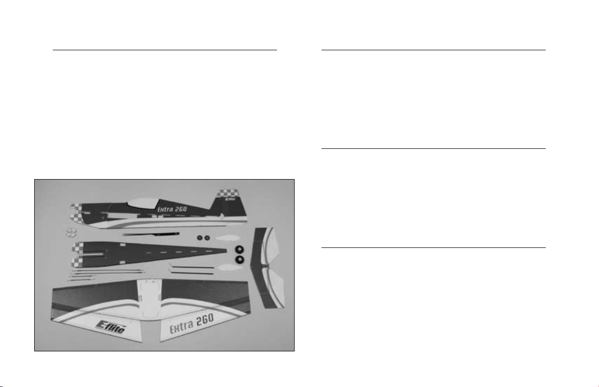
Contents of Kit/Parts Layout
Outrunner Setup
Small Replacement Parts
EFL2305 Wheel Pants
EFL2306 Firewall Mount w/Hardware
EFL2307 Aileron Rods
EFL2308 Carbon Fiber Stiffeners
EFL2309 Landing Gear
EFLA200 Micro Control Horns
FLA203 Micro Control Connectors
EFLA221 Foam Park Wheels, 1.5"
EFLM1150 Park 300 Brushless Outrunner Motor,
1380Kv
EFLA1010 10-Amp Pro Brushless ESC
APC08038SF 8x3.8 Slow Flyer Prop
THP4803SJPL 480mAh 3-Cell 11.1V Li-Po, JST
EFLC3005 Celectra™ 1–3 Cell Li-Po Charger
Variable Prop Outrunner Setup
EFLPVPP100 Showtime Variable Pitch Prop
EFLM1210HS Park 370 BL Outrunner, 1200Kv w/4mm
Hollow Shaft
EFLA1010 10-Amp Pro Brushless ESC
THP7303SJPL 730mAh 3-Cell 11.1V Li-Po, JST
EFLC3005 Celectra 1–3 Cell Li-Po Charger
Optional Accessories
EFLA110 Power Meter
4
Page 5

Required Radio Equipment
You will need a minimum 6-channel transmitter (for proper
mixing and dual rate capabilities), crystals, micro receiver,
and three sub-micro servos. You can choose to purchase
a complete radio system that includes all of these items
or, if you are using an existing transmitter, just purchase
the other required equipment separately. We recommend
the crystal-free, interference-free Spektrum® DX6 2.4GHz
DSM® 6-channel system, which includes a micro receiver
and 4 sub-micro 7.5 gram servos. If using your own
transmitter, we recommend the use of a JR SPORT™
6-channel UltraLite receiver and E-flite® S60 Super
Sub-Micro servos.
Complete Radio System
SPM2460 DX6 DSM 6CH Park Flyer w/4-S75
Or Purchase Separately
JSP30610 6-Channel UltraLite Rx w/o Crystal,
Positive Shift JR/AIR (72MHz)
JSP30615 6-Channel UltraLite Rx w/o Crystal,
Negative Shift Fut/HRC (72MHz)
JRPXFR** FM Receiver Crystal (JR only,
not AR6000)
Or
SPM6000 AR6000 DSM 6-Channel Park Flyer
Receiver
And
EFLRS60 6.0-Gram Super Sub-Micro Servo (4)
(5 with optional Variable Pitch Propeller)
5
Page 6

Warning
Required Tools and Adhesives
An RC aircraft is not a toy! If misused, it can cause
serious bodily harm and damage to property. Fly
only in open areas, preferably at AMA (Academy of
Model Aeronautics) approved flying sites, following all
instructions included with your radio.
Keep loose items that can get entangled in the propeller
away from the prop, including loose clothing, or other
objects such as pencils and screwdrivers. Especially keep
your hands away from the propeller.
Tools & Equipment
EFLA250 Park Flyer Tool Assortment, 5-piece
Or Purchase Separately
EFLA257 Screwdriver, #0 Phillips (or included with
EFLA250)
Drill
Drill bit: 1/16" (1.5mm)
Cardstock
Foam Safe CA, Medium (EFLA209)
Foam Safe Accelerator (EFLA207)
Low Temperature Glue Gun w/Hot Glue
Hobby knife
Felt-tipped pen
Pliers
Square
Sandpaper
6
Page 7

Note on Lithium Polymer Batteries
Limited Warranty Period
Lithium Polymer batteries are significantly
more volatile than alkaline or Ni-Cd/
Ni-MH batteries used in RC applications. All
manufacturer’s instructions and warnings must
be followed closely. Mishandling of
Li-Po batteries can result in fire. Always
follow the manufacturer’s instructions when
disposing of Lithium Polymer batteries.
Horizon Hobby, Inc. guarantees this product to be free
from defects in both material and workmanship at the date
of purchase.
7
Page 8

Limited Warranty & Limits of Liability
Pursuant to this Limited Warranty, Horizon Hobby, Inc.
will, at its option, (i) repair or (ii) replace, any product
determined by Horizon Hobby, Inc. to be defective. In the
event of a defect, these are your exclusive remedies.
This warranty does not cover cosmetic damage or damage
due to acts of God, accident, misuse, abuse, negligence,
commercial use, or modification of or to any part of
the product. This warranty does not cover damage due
to improper installation, operation, maintenance, or
attempted repair by anyone other than an authorized
Horizon Hobby, Inc. service center. This warranty is
limited to the original purchaser and is not transferable.
In no case shall Horizon Hobby’s liability exceed the
original cost of the purchased product and will not
cover consequential, incidental or collateral damage.
Horizon Hobby, Inc. reserves the right to inspect any and
all equipment involved in a warranty claim. Repair or
replacement decisions are at the sole discretion of Horizon
Hobby, Inc. Further, Horizon Hobby reserves the right to
change or modify this warranty without notice.
REPAIR OR REPLACEMENT AS PROVIDED UNDER
THIS WARRANTY IS THE EXCLUSIVE REMEDY OF THE
CONSUMER. HORIZON HOBBY, INC. SHALL NOT BE
LIABLE FOR ANY INCIDENTAL OR CONSEQUENTIAL
DAMAGES.
As Horizon Hobby, Inc. has no control over use, setup,
final assembly, modification or misuse, no liability shall be
assumed nor accepted for any resulting damage or injury.
By the act of use, setup or assembly, the user accepts all
resulting liability.
If you as the purchaser or user are not prepared to accept
the liability associated with the use of this product, you
are advised to return this product immediately in new and
unused condition to the place of purchase.
8
Page 9

Safety Precautions
Questions or Assistance
This is a sophisticated hobby product and not a toy. It
must be operated with caution and common sense and
requires some basic mechanical ability. Failure to operate
this product in a safe and responsible manner could result
in injury or damage to the product or other property. This
product is not intended for use by children without direct
adult supervision.
The product manual contains instructions for safety,
operation and maintenance. It is essential to read and
follow all the instructions and warnings in the manual,
prior to assembly, setup or use, in order to operate
correctly and avoid damage or injury.
Questions, Assistance, and Repairs
Your local hobby store and/or place of purchase cannot
provide warranty support or repair. Once assembly, setup
or use of the product has been started, you must contact
Horizon Hobby, Inc. directly. This will enable Horizon to
better answer your questions and service you in the event
that you may need any assistance.
For questions or assistance, please direct your email to
productsupport@horizonhobby.com, or call 877.504.0233
toll-free to speak to a service technician.
Inspection or Repairs
If your product needs to be inspected or repaired, please
call for a Return Merchandise Authorization (RMA). Pack
the product securely using a shipping carton. Please note
that original boxes may be included, but are not designed
to withstand the rigors of shipping without additional
protection. Ship via a carrier that provides tracking and
insurance for lost or damaged parcels, as Horizon Hobby,
Inc. is not responsible for merchandise until it arrives and
is accepted at our facility. Include your complete name,
address, phone number where you can be reached during
business days, RMA number, and a brief summary of the
problem. Be sure your name, address, and RMA number
are clearly written on the shipping carton.
9
Page 10

Warranty Inspection and Repairs
To receive warranty service, you must include your
original sales receipt verifying the proof-of-purchase
date. Providing warranty conditions have been met, your
product will be repaired or replaced free of charge.
Repair or replacement decisions are at the sole discretion
of Horizon Hobby.
Non-Warranty Repairs
Should your repair not be covered by warranty and the
expense exceeds 50% of the retail purchase cost, you will
be provided with an estimate advising you of your options.
You will be billed for any return freight for non-warranty
repairs. Please advise us of your preferred method of
payment. Horizon Hobby accepts money orders and
cashiers checks, as well as Visa, MasterCard, American
Express, and Discover cards. If you choose to pay by
credit card, please include your credit card number and
expiration date. Any repair left unpaid or unclaimed
after 90 days will be considered abandoned and will be
disposed of accordingly.
Electronics and engines requiring inspection or repair
should be shipped to the following address (freight
prepaid):
Horizon Service Center
4105 Fieldstone Road
Champaign, Illinois 61822
All other products requiring inspection or repair should be
shipped to the following address (freight prepaid):
Horizon Product Support
4105 Fieldstone Road
Champaign, Illinois 61822
10
Page 11

Safety, Precautions, and Warnings
As the user of this product, you are solely responsible for
operating it in a manner that does not endanger yourself
and others or result in damage to the product or the
property of others.
Carefully follow the directions and warnings for this and
any optional support equipment (chargers, rechargeable
battery packs, etc.) that you use.
This model is controlled by a radio signal that is subject to
interference from many sources outside your control. This
interference can cause momentary loss of control so it is
necessary to always keep a safe distance in all directions
around your model, as this margin will help to avoid
collisions or injury.
• Always operate your model in an open area away from
cars, traffic, or people.
• Avoid operating your model in the street where injury or
damage can occur.
• Never operate the model out into the street or populated
areas for any reason.
• Never operate your model with low transmitter batteries.
• Carefully follow the directions and warnings for this and
any optional support equipment (chargers, rechargeable
battery packs, etc.) that you use.
• Keep all chemicals, small parts and anything electrical
out of the reach of children.
• Moisture causes damage to electronics. Avoid water
exposure to all equipment not specifically designed and
protected for this purpose.
11
Page 12
Airframe Assembly
Required Parts
Vertical fuselage
Horizontal fuselage
Wing w/ailerons
Stabilizer w/elevators
Motor mount
Required Tools and Adhesives
Foam-safe CA, Medium
Foam-safe accelerator (can be used to speed up cure time)
Square
1. Locate the vertical and horizontal fuselage
pieces. Slide the horizontal fuselage into the
vertical fuselage starting at the opening for
the wing/radio equipment. Use care not to
damage any of the alignment tabs on the vertical
fuselage.
12
Page 13
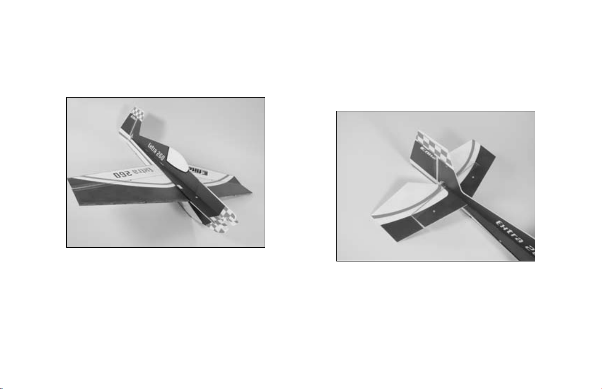
2. Locate the wing and slide it into the vertical
fuselage underneath the horizontal fuselage.
Use care not to damage either the vertical or
horizontal fuselage pieces.
Hint: Fold one of the ailerons up and onto
the wing to make it a little narrower to install
into the fuselage. Push the wing past center to
move the aileron back into position, then center
the wing.
3. Slide the horizontal stabilizer into the fuselage,
being careful not to damage any of the alignment
tabs. You may need to move the horizontal
fuselage out of the vertical fuselage slightly to get
the stabilizer into position.
13
Page 14
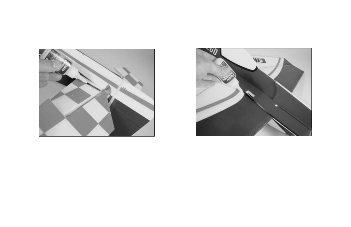
4. Align the stabilizer with the horizontal fuselage.
Use foam-safe CA to glue the stabilizer to ONLY
the horizontal fuselage.
5. Align the wing with the horizontal fuselage.
Use foam-safe CA to glue the wing to ONLY the
horizontal fuselage.
Hint: Use the holes for the aileron servos to
aid in the alignment between the horizontal
fuselage and wing.
Note: There are slots at the front and rear of
the wing. Lightly lift the area and apply CA
underneath for a greater gluing area.
14
Page 15

Important: If you plan on using CA accelerator,
make sure it is foam compatible. Many
accelerators will destroy the foam used on this
model.
6. Place the motor mount in position to aid in
the alignment of the vertical and horizontal
fuselage pieces. DO NOT glue the mount until
instructed to do so. Position the horizontal and
vertical fuselage pieces until the mount rests flush
against both.
7. Apply foam-safe CA to the joint between the
vertical and horizontal fuselage pieces from
the leading edge of the wing to the front of the
fuselage. Use a square to make sure the two
pieces are aligned. Apply CA to both the top and
bottom of the vertical fuselage.
15
Page 16

8. Complete gluing the vertical and horizontal
fuselage pieces together. Continue to use a
square to keep both pieces in alignment.
16
Page 17

Installing the Bracing
Required Parts
Assembled airframe
Carbon rod, 9
Carbon rod, 9
Carbon rod, 4
Carbon rod, 4
Carbon rod, 4
Required Tools and Adhesives
Foam-safe CA, Medium
Sandpaper
Hobby knife
Note: It is important that each carbon
rod attaches to the next, and to the
carbon blade spars on the edges of the
foam. This is necessary to provide the
stiffest airframe possible.
7
/
" (250mm) (2)
8
1
/
" (240mm) (2)
2
3
/
" (120mm) (2)
4
1
/
" (113mm) (4)
2
1
/
" (105mm) (4)
8
1. Locate the two 4
3
/
" (120mm) carbon rods.
4
Pass the rods through the fin and stabilizer.
Use foam-safe CA to glue the rods to the fin
ONLY at this time.
17
Page 18

2. Place the 4
1
/
" (113mm) carbon rods on the
2
bottom of the stabilizer to the bottom of the
vertical fuselage. There is a notch in the fuselage
for the rods to rest in. Make sure the rods are
touching each other as well as the carbon blade
spar. Use foam-safe CA to glue the rods at the
fuselage ONLY.
3. Check the alignment of the fin to the stabilizer.
They should be perpendicular to each other.
Check that the rods in the stabilizer are
touching. Use foam-safe CA to glue the rods
into position after checking alignment and that the
rods are touching.
18
Page 19

4. Locate two of the 4
1
/
" (105mm) carbon rods.
8
Install these rods, like the rods installed in Step
3, to the horizontal fuselage. Again, there are
notches for the carbon rods. Make sure the rods
are touching the previously installed rods and the
pre-installed carbon blade spars on the edges of
the foam.
5. The next rod to install is the 4
1
rod from the rod in Step 4 to the bottom of
the vertical fuselage.
/
" (113mm)
2
19
Page 20

6. To complete the fuselage bracing, install a 4
1
/
(105mm) rod from the previous rod back down to
the horizontal fuselage. You will need to trim the
fuselage to expose the carbon support so the rod
can be glued securely to the brace.
7. Check the joints in Steps 1 through 6 to ensure
you have a nice fillet of CA at every junction
where you have glued the carbon rods to each
other and the fuselage. Apply additional CA if
necessary to create this fillet.
"
8
8. Installing the wing bracing is similar to installing
the fuselage bracing, as you want the rods to be
glued to the carbon bracing that has been preinstalled on the wing and fuselage. The longer
7
9
/
" (250mm) rod is positioned toward the
8
aileron, while the shorter 9
1
/
" (240mm) rod is
2
toward the leading edge. The rods are staggered
and fit into notches in the fuselage. Make sure
the rods are straight and are not flexing the
wing. Use foam-safe CA to glue the rods in
position. The wing should be flat and parallel
to the horizontal stabilizer, while also being
perpendicular to the vertical fuselage.
20
Page 21

21
Page 22

Radio Installation
Required Parts
Airframe
Servos (4)
Micro control connector (4)
Control connector backplate (4)
Micro control horn (4)
Control horn backplate (4)
2mm x 4mm screw (4)
Aileron pushrods, 4
Rudder pushrod, 12" (305mm)
Elevator pushrod, 12
Hook and loop material
Required Tools and Adhesives
Foam-safe CA, Medium
Low-temperature hot glue
Drill bit: 1/16" (1.5mm)
Screwdriver, #0 Phillips
1
/
" (115mm) (2)
2
1
/
" (320mm)
2
1. Install the micro control horn on the aileron using
the control horn backplate. Use a couple drops of
foam-safe CA to keep the backplate in position.
22
Page 23

2. Install the rudder and elevator micro control horns
at this time as well. Make sure the rudder horn
extends opposite of the elevator horn.
3. Remove the servo arms from the four servos.
Drill a 1/16" (1.5mm) hole in the end of all four
of the servo arms.
Note: We then suggest using the longest servo
arms available for your servo to help achieve
maximum control throws for 3D flying.
23
Page 24

4. Slide a micro control connector into the hole
drilled in the previous step. Secure the connector
using a control connector backplate from the
opposite side of the connector. Repeat for all four
servo arms.
Note: The connectors will face out away from
the servo when installed. Remove any unused
sides or portions of the servo arms.
5. Plug the servos into the receiver. Turn on the
transmitter and receiver and check the operation
of the servos. After centering the trims and subtrims, attach the servo arms as shown. Note the
direction of the arms on the servos creates two
pairs of servos: one for ailerons, and one for
rudder/elevator.
24
Page 25

6. Use hot glue to install the aileron servos.
Note: The servo arms face toward the tips of the
wing and the output shaft of the servo is toward
the leading edge of the wing.
7. Install the rudder and elevator servos using hot
glue. The output shafts of both servos face the
front of the aircraft.
25
Page 26

8. Locate the 4
1
/
" (115mm) pushrod. Install the
2
“Z” bend into the hole of the control horn that
is one away from the aileron. This will provide
for 3D throws of the aileron. Pass the pushrod
through the connector. Check that the aileron
servo is centered using the radio. Hold the aileron
parallel to the wing and use the 2mm x 4mm
screw in the connector to secure the pushrod wire.
Repeat this for the other aileron pushrod.
Note: Use the hole in the control horn closest
to the aileron for the greatest amount of throw.
Moving the pushrod outward, away from the
aileron, will result in gradually decreasing the
control throws.
26
Page 27

9. Install the 12" (305mm) pushrod for the rudder,
and the 12
Don’t forget to check to make sure the servos and
control surfaces are centered before tightening the
2mm x 4mm screws.
1
/
" (320mm) pushrod for the elevator.
2
10. Install the receiver using hook and loop
material. The exact position of the receiver
may change, depending on how your
aircraft balances.
27
Page 28

Motor and Battery Installation
Required Parts
Airframe
Plywood motor mount
Motor w/hardware
Electronic speed control
Propeller
#2 x 8mm or #3 x 8mm wood screw (included with motor)
Hook and loop material
Required Tools and Adhesives
Foam-safe CA, Medium
Drill bit: 1/16" (1.5mm)
Cardstock
Felt-tip pen
Hobby Knife
Screwdriver, #0 Phillips
Optional
Variable pitch prop
Sub-micro servo (1)
1. Locate the plywood motor mount and aluminum
X-mount for your particular motor. Center
the motor mount on the plywood and mark
the holes for the mounting screws using a
felt-tipped pen making sure the holes you mark
do not interfere with the carbon spars the mount
will glue into.
Hint: If the hole in your mount matches the
diameter of the hole in the plywood mount, use
a rolled-up piece of cardstock placed through
the two holes to center the motor mount on the
plywood mount.
28
Page 29

2. Drill pilot holes for the mounting holes marked
on the plywood mount using a 1/16" (1.5mm)
drill bit.
Note: If you are using a variable pitch propeller
for your Extra, you should prepare the motor as
instructed in the instructions included with your
propeller system.
3. Attach the mount to your particular motor.
29
Page 30

4. Attach the motor to the plywood mount using
two #2 x 8mm wood screws or two #3 x 8mm
wood screws.
5. Use a hobby knife to remove the fuselage
material from the variable pitch servo pushrod
slot opening mount to the front of the fuselage.
30
Page 31

6. Use foam-safe CA to glue the plywood mount to
the fuselage. Make sure the mount is pressed fully
against the fuselage, with each carbon support in
each slot, to make sure it is aligned properly.
Note: Steps 7 and 8 cover the installation of the
servo and linkage for a variable pitch propeller.
Skip to Step 9 if you are not using a variable
pitch propeller.
Note: Be sure to consult the manual for
your chosen variable pitch prop unit before
proceeding with installation of the pitch servo
and linkage. Due to the variety of VPP systems
available, there may be some variation in how
the servo and linkage can be installed.
7. Check that the linkage for your variable pitch
prop unit can move freely without binding on the
fuselage. Trim away any material necessary if any
binding is noticed.
31
Page 32

8. Install the pitch servo as shown. Take your time
to make sure the servo horn and linkage does
not bind against the fuselage. Also check that
the linkage is not being put under a load when
connected. Use a hobby knife to remove any
portions of the fuselage that cause binding. Use
foam-safe CA or hot glue to secure the servo to
the fuselage.
32
Page 33

9. Solder any necessary connectors to your
speed control. Plug the speed control into the
throttle channel of the receiver and to the motor.
Use hook and loop to secure the speed control
to the fuselage.
Note: It is suggested to secure the motor wires
to the fuselage to prevent them from coming
in contact with the propeller or servos when
performing extreme maneuvers.
10. Attach the battery under the wing using
hook and loop material. The location shown is
an approximate location and can be repositioned
as necessary to achieve the correct balance for
your Extra.
33
Page 34

11. Turn on the transmitter and bring the throttle
trim and stick to the low throttle position. Plug
the battery into the speed control and check
the operation of the motor. It should rotate
counterclockwise when viewed from the front of
the aircraft. Use the instructions provided with
your ESC to make corrections to the direction of
rotation of the motor if necessary.
12. Install the propeller using the instructions
provided with your motor or propeller system.
34
Page 35

Landing Gear Installation
Required Parts
Airframe
Landing gear strut (2)
Wheel retainer (4)
Wheel pant (2)
1
1
/
" (38mm) foam wheel (2)
2
Landing gear support disk (2)
Required Tools and Adhesives
Foam-safe CA
The landing gear is optional. If you plan
on saving weight, or flying from very rough
surfaces, it is suggested to skip this section.
1. Locate the landing gear strut, two wheel
retainers and the wheel. Use foam-safe CA
to install the wheel retainer onto the strut. The
retainers will sandwich the wheel in position.
Note: Use care not to get CA on the wheel,
preventing it from rotating on the strut.
35
Page 36

2. Pass the landing gear through the opening in
the fuselage and wing. DO NOT use glue until
instructed to do so.
4. The struts should extend roughly 3/32" (2.5mm)
through the top of the wing. This will give the
landing gear support disks plenty of strut to
attach to.
3. Repeat Steps 1 and 2 for the remaining strut.
36
Hint: You can just drop the disks into position
and check to make sure the strut extends
beyond the disk instead of measuring it.
Page 37

5. Check that the wheels are parallel or have slight
toe-in. Use foam-safe CA to glue the struts to the
fuselage and each other. Make sure the wing is
sitting parallel to the ground so the wheels are
located at the same height.
6. Install the landing gear support disks using
foam-safe CA. Make sure to glue the disks
securely to both the horizontal fuselage and
landing gear struts.
7. Use foam-safe CA to glue the wheel pants to
the wheel retainers. Make sure the pants are
positioned so they won’t drag on the ground
during takeoff and landing before applying
the CA.
37
Page 38

Control Throws
Turn on the transmitter and receiver of your Extra 260.
Check the movement of the rudder, elevator and ailerons
using the transmitter. Reverse the direction of the servos at
the transmitter if necessary.
Use a ruler to adjust the throw of the elevator, ailerons and
rudder. Adjust the position of the pushrod at the control
horn to achieve the following measurements when moving
the sticks to their endpoints.
Measurements are taken at the widest point on the surface.
Low Rate High Rate
Ailerons:
Up/Down 1
1
/
" (38mm) 2
2
1
/
" (57mm)
4
Elevator:
Up/Down 1
1
/
" (32mm) 2
4
1
/
" (63mm)
2
Rudder:
Right/Left 2" (51mm) 3" (76mm)
These are general guidelines measured from our own flight
tests. You can experiment with higher rates to match your
preferred style of flying.
The following are the control throws suggested by
George Hicks:
Ailerons:
Up/Down 3" (76mm) (55 degrees)
Rudder:
Right/Left 3
1
/
" (79mm) (55 degrees)
8
Elevator:
Up/Down 2
1
/
" (63mm) (55 degrees)
2
Note: George Hicks' recommended throws
should be considered for advanced pilots only.
Visit our web site at www.horizonhobby.com or
www.E-fliteRC.com for George Hicks’ flying tips.
38
Page 39

Center of Gravity
Caution: Do not inadvertently skip this step!
The recommended Center of Gravity (CG) location for the
Extra 260 is 3
wing against the fuselage. After the first flights, the CG
position can be adjusted for your personal preference.
1
/
" (90mm) behind the leading edge of the
2
Range Testing the Radio
1. Be sure to range check your radio before each
flying session. This is accomplished by turning
on your transmitter with the antenna collapsed.
Turn on the receiver in your airplane. With
your airplane on the ground and the engine
running, you should be able to walk 30 paces
(approximately 100 feet) away from your
airplane and still have complete control of all
functions. If not, don’t attempt to fly! Have your
radio equipment checked out by the manufacturer.
2. Double-check that all controls (aileron, elevator,
rudder and throttle) move in the correct direction.
3. Be sure that your transmitter batteries are
fully charged, per the instructions included
with your radio.
39
Page 40

Preflight
Check Your Radio
Before going to the field, be sure that your batteries are
fully charged per the instructions included with your radio.
Charge both the transmitter and receiver pack for your
airplane. Use the recommended charger supplied with
your particular radio system, following the instructions
provided with the radio. In most cases, the radio should be
charged the night before going out flying.
Before each flying session, be sure to range check your
radio. See your radio manual for the recommended
range and instructions for your radio system. Each radio
manufacturer specifies different procedures for their
radio systems. Next, start the motor. With the model
securely anchored, check the range again. The range test
should not be significantly affected. If it is, don’t attempt
to fly! Have your radio equipment checked out by the
manufacturer.
Note: Keep loose items that can get entangled
in the propeller away from the prop. These
include loose clothing, or other objects such as
pencils and screwdrivers. Especially keep your
hands away from the propeller.
Double-check that all controls (aileron, elevator, rudder
and throttle) move in the correct direction.
Check the radio installation and make sure all the
control surfaces are moving correctly (i.e. the correct
direction and with the recommended throws). Test run
the motor and make sure it transitions smoothly from
off to full throttle and back. Also ensure the engine is
installed according to the manufacturer’s instructions,
and it will operate consistently.
Check all the control horns, servo horns, and clevises to
make sure they are secure and in good condition. Replace
any items that would be considered questionable. Failure
of any of these components in flight would mean the loss
of your aircraft.
40
Page 41

Notes
41
Page 42

2006 Official AMA National Model Aircraft Safety Code
GENERAL
1) I will not fly my model aircraft in sanctioned events,
air shows or model flying demonstrations until it has
been proven to be airworthy by having been previously,
successfully flight tested.
2) I will not fly my model higher than approximately 400
feet within 3 miles of an airport without notifying the
airport operator. I will give right-of-way and avoid flying
in the proximity of full-scale aircraft. Where necessary,
an observer shall be utilized to supervise flying to avoid
having models fly in the proximity of full-scale aircraft.
3) Where established, I will abide by the safety rules
for the flying site I use, and I will not willfully or
deliberately fly my models in a careless, reckless
and/or dangerous manner.
4) The maximum takeoff weight of a model is 55 pounds,
except models flown under Experimental Aircraft rules.
5) I will not fly my model unless it is identified with my
name and address or AMA number on or in the model.
(This does not apply to models while being flown indoors.)
6) I will not operate models with metal-bladed propellers
or with gaseous boosts, in which gases other than air
enter their internal combustion engine(s); nor will I operate
models with extremely hazardous fuels such as those
containing tetranitromethane or hydrazine.
RADIO CONTROL
1) I will have completed a successful radio equipment
ground range check before the first flight of a new or
repaired model.
2) I will not fly my model aircraft in the presence of
spectators until I become a qualified flier, unless assisted
by an experienced helper.
3) At all flying sites a straight or curved line(s) must be
established in front of which all flying takes place with the
other side for spectators. Only personnel involved with
flying the aircraft are allowed at or in front of the flight
line. Intentional flying behind the flight line is prohibited.
42
Page 43

2006 Official AMA National Model Aircraft Safety Code
4) I will operate my model using only radio control
frequencies currently allowed by the Federal
Communications Commission. (Only properly licensed
Amateurs are authorized to operate equipment on
Amateur Band frequencies.)
5) Flying sites separated by three miles or more are
considered safe from site-to-site interference, even when
both sites use the same frequencies. Any circumstances
under three miles separation require a frequency
management arrangement, which may be either an
allocation of specific frequencies for each site or testing to
determine that freedom from interference exists. Allocation
plans or interference test reports shall be signed by the
parties involved and provided to AMA Headquarters.
Documents of agreement and reports may exist between
(1) two or more AMA Chartered Clubs, (2) AMA clubs
and individual AMA members not associated with AMA
Clubs, or (3) two or more individual AMA members.
6) For Combat, distance between combat engagement
line and spectator line will be 500 feet per cubic inch of
engine displacement. (Example: .40 engine = 200 feet.);
electric motors will be based on equivalent combustion
engine size. Additional safety requirements will be per the
RC Combat section of the current Competition Regulations.
7) At air shows or model flying demonstrations, a single
straight line must be established, one side of which is for
flying, with the other side for spectators.
8) With the exception of events flown under AMA
Competition rules, after launch, except for pilots or helpers
being used, no powered model may be flown closer than
25 feet to any person.
9) Under no circumstances may a pilot or other person
touch a powered model in flight.
43
Page 44

9252
®
© 2006 Horizon Hobby, Inc.
4105 Fieldstone Road
Champaign, Illinois 61822
(877) 504-0233
horizonhobby.com
E-fliteRC.com
 Loading...