

Page 1
Cap 232 BP 3D
Assembly Manual
Page 2

Table of Contents
Introduction ................................................................3
Specifications .............................................................3
Using the Manual
Contents of Kit/Parts Layout
Required Radio Equipment
Important Information About Motor Selection
High Power Outrunner Setup
Lightweight Outrunner Setup
Optional Accessories
Note on Lithium Polymer Batteries
Required Tools and Adhesives
Warning ....................................................................7
Date of Purchase Warranty Period
Limited Warranty
Damage Limits
Safety Precautions
Questions, Assistance, and Repairs
Inspection or Repairs
Warranty Inspection and Repairs
.......................................................3
.........................................4
...........................................5
.................5
........................................6
........................................6
..................................................6
.................................6
......................................7
................................7
........................................................8
............................................................9
.......................................................9
...............................9
.................................................10
................................10
Non-Warranty Repairs ...............................................11
Safety, Precautions, and Warnings
Airframe Assembly
Hinging ...................................................................18
Landing Gear Installation
Radio Installation
Power System Installation
Control Throws
Center of Gravity
Range Test Your Radio
Preflight ...................................................................40
Flying Your Cap 232 BP
2006 Official AMA
National Model Aircraft Safety Code
....................................................13
...........................................22
......................................................25
...........................................33
.........................................................38
......................................................39
...............................................39
............................................41
..............................12
..........................42
2
Page 3

Introduction
Using the Manual
The Cap 232 BP 3D combines the sturdy construction of a
balsa/light-ply airframe with the uninhibited 3D capability
of a lightweight profile park flyer. It’s all made possible
by its intelligently engineered, open structure design that
keeps weight to a bare minimum while providing all the
structural integrity of a real wood airframe. This featherlight construction, combined with a high-output brushless
motor, will provide spine-tingling 3D and freestyle
performance that will let you really push the limits. And it
comes from the factory 90% built and covered in genuine
UltraCote® and UltraCote Light so you can be up and
flying in no time
Specifications
Wingspan: 35.5 in (900mm)
Length: 35.5 in (900mm)
Wing Area: 425 sq in (27.5 sq dm)
Weight w/o Battery: 13–14 oz (370–400 g)
Weight w/ Battery: 15.5–17 oz (440–480 g)
This manual is divided into sections to help make assembly
easier to understand, and to provide breaks between each
major section. In addition, check boxes have been placed
next to each step to keep track of each step completed.
Steps with a single circle () are performed once, while
steps with two circles ( ) indicate that the step will
require repeating, such as for a right or left wing panel,
two servos, etc.
Remember to take your time and follow the directions.
3
Page 4
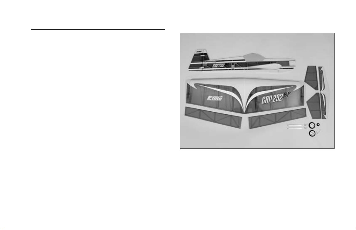
Contents of Kit/Parts Layout
Large Replacement Parts
EFL2401 Wing w/Ailerons
EFL2402 Fuselage with Rudder
EFL2403 Horizontal Tail Assembly
EFL2405 Landing Gear
Small Replacement Parts
EFL2404 Pushrod Set
EFL2406 Hardware Set
EFL2407 Wheel Set
EFLA213 E-flite/JR/Horizon Decals
EFLM1915 Outrunner Stick Mount
4
Page 5

Required Radio Equipment
You will need a minimum 6-channel transmitter, crystals,
micro receiver, and four sub-micro servos. You can choose
to purchase a complete radio system that includes all of
these items or, if you are using an existing transmitter, just
purchase the other required equipment separately.
Complete Radio System
SPM2460 DX6 DSM® 6CH Park Flyer
w/4-S75 Servos
Note: We recommend the crystal-free,
interference-free Spektrum® DX6 2.4GHz DSM
6-Channel System, which includes a micro
receiver and 4 sub-micro servos.
Or Purchase Separately
SPM6000 AR6000 DSM DuaLink™ 6-Channel
Park Flyer Rx
Or
JSP30610 6-Channel UltraLite Rx w/o Crystal,
Positive Shift JR/AIR (72MHz)
Or
JSP30615 6-Channel UltraLite Rx w/o Crystal,
Negative Shift FUT/HRC (72MHz)
JRPXFR** FM Receiver Crystal
EFLRS75 7.5-Gram Sub-Micro Servo (4)
Important Information About Motor
Selection
We recommend the E-flite® Park 450 Brushless
Outrunner, 890Kv (EFLM1400) to provide you with
excellent high-power motor system, or the Park 400
Brushless Outrunner 920 Kv (EFLM1305) for sport power
and a worry-free outrunner motor. The Cap 232 BP 3D
does not include a propeller.
5
Page 6

High Power Outrunner Setup
Optional Accessories
EFLM1400 Park 450 BL Outrunner, 890Kv
EFLA311B 20-Amp Brushless ESC
THP13203SPL 1320mAh 3-Cell 11.1V Li-Po
APC11038SF 11 x 3.8 Electric Prop
EFLAEC303 EC3 Device & Battery Connector,
Male/Female
EFLC3005 Celectra 1- to 3-Cell Li-Po Charger
This is a high-power performance setup for strong
3D flights.
Lightweight Outrunner Setup
EFLM1305 Park 400 BL Outrunner, 920Kv
EFLA311B 20-Amp Brushless ESC
THP9103SJPL 910mAh 3-Cell 11.1V Li-Po
APC11038SF 11 x 3.8 Electric Prop
EFLAEC303 EC3 Device & Battery Connector,
Male/Female
EFLC3005 Celectra 1- to 3-Cell Li-Po Charger
This is a lightweight sport setup with adequate power
for 3D flights.
EFLA110 Power Meter
Note on Lithium Polymer Batteries
Lithium Polymer batteries are significantly
more volatile than alkaline or Ni-Cd/
Ni-MH batteries used in RC applications.
All manufacturer’s instructions and warnings
must be followed closely. Mishandling of Li-Po
batteries can result in fire. Always follow the
manufacturer’s instructions when disposing of
Lithium Polymer batteries.
6
Page 7

Required Tools and Adhesives
Warning
Tools & Equipment
EFLA250 Park Flyer Tool Assortment, 5-piece
Or Purchase Separately
EFLA257 Screwdriver, #0 Phillips (or included
with EFLA250)
EFLA251 Hex Wrench: 3/32” (or included
with EFLA250)
Drill
Drill bit: 1/16” (1.5mm), 5/64” (2mm)
Felt-tipped pen
String
Straight edge
Threadlock
Razor saw
T-pins
Thin CA
Medium CA
Paper towels
Hobby knife (#11 blade)
6-minute epoxy
Pliers
Ruler
Square
Sandpaper
An RC aircraft is not a toy! If misused, it can cause
serious bodily harm and damage to property. Fly
only in open areas, preferably at AMA (Academy of
Model Aeronautics) approved flying sites, following all
instructions included with your radio.
Keep loose items that can get entangled in the propeller
away from the prop, including loose clothing, or other
objects such as pencils and screwdrivers. Especially keep
your hands away from the propeller.
Date of Purchase Warranty Period
Horizon Hobby, Inc., (Horizon) warranties that the
Products purchased (the “Product”) will be free from
defects in materials and workmanship at the date of
purchase by the Purchaser.
7
Page 8

Limited Warranty
(a) This warranty is limited to the original Purchaser
("Purchaser") and is not transferable. REPAIR OR
REPLACEMENT AS PROVIDED UNDER THIS WARRANTY
IS THE EXCLUSIVE REMEDY OF THE PURCHASER. This
warranty covers only those Products purchased from an
authorized Horizon dealer. Third party transactions are
not covered by this warranty. Proof of purchase is required
for warranty claims. Further, Horizon reserves the right
to change or modify this warranty without notice and
disclaims all other warranties, express or implied.
(b) Limitations- HORIZON MAKES NO WARRANTY
OR REPRESENTATION, EXPRESS OR IMPLIED, ABOUT
NON-INFRINGEMENT, MERCHANTABILITY OR FITNESS
FOR A PARTICULAR PURPOSE OF THE PRODUCT. THE
PURCHASER ACKNOWLEDGES THAT THEY ALONE
HAVE DETERMINED THAT THE PRODUCT WILL SUITABLY
MEET THE REQUIREMENTS OF THE PURCHASER’S
INTENDED USE.
(c) Purchaser Remedy- Horizon's sole obligation hereunder
shall be that Horizon will, at its option, (i) repair or
(ii) replace, any Product determined by Horizon to be
defective. In the event of a defect, these are the Purchaser's
exclusive remedies. Horizon reserves the right to inspect
any and all equipment involved in a warranty claim.
Repair or replacement decisions are at the sole discretion
of Horizon. This warranty does not cover cosmetic damage
or damage due to acts of God, accident, misuse, abuse,
negligence, commercial use, or modification of or to any
part of the Product. This warranty does not cover damage
due to improper installation, operation, maintenance, or
attempted repair by anyone other than Horizon. Return of
any goods by Purchaser must be approved in writing by
Horizon before shipment.
8
Page 9

Damage Limits
Safety Precautions
HORIZON SHALL NOT BE LIABLE FOR SPECIAL,
INDIRECT OR CONSEQUENTIAL DAMAGES, LOSS OF
PROFITS OR PRODUCTION OR COMMERCIAL LOSS IN
ANY WAY CONNECTED WITH THE PRODUCT, WHETHER
SUCH CLAIM IS BASED IN CONTRACT, WARRANTY,
NEGLIGENCE, OR STRICT LIABILITY. Further, in no event
shall the liability of Horizon exceed the individual price of
the Product on which liability is asserted. As Horizon has
no control over use, setup, final assembly, modification
or misuse, no liability shall be assumed nor accepted for
any resulting damage or injury. By the act of use, setup or
assembly, the user accepts all resulting liability.
If you as the Purchaser or user are not prepared to accept
the liability associated with the use of this Product, you
are advised to return this Product immediately in new and
unused condition to the place of purchase.
Law: These Terms are governed by Illinois law (without
regard to conflict of law principals).
This is a sophisticated hobby Product and not a toy. It
must be operated with caution and common sense and
requires some basic mechanical ability. Failure to operate
this Product in a safe and responsible manner could result
in injury or damage to the Product or other property. This
Product is not intended for use by children without direct
adult supervision. The Product manual contains instructions
for safety, operation and maintenance. It is essential
to read and follow all the instructions and warnings in
the manual, prior to assembly, setup or use, in order to
operate correctly and avoid damage or injury.
Questions, Assistance, and Repairs
Your local hobby store and/or place of purchase
cannot provide warranty support or repair. Once
assembly, setup or use of the Product has been started,
you must contact Horizon directly. This will enable
Horizon to better answer your questions and service
you in the event that you may need any assistance. For
questions or assistance, please direct your email t
o productsupport@horizonhobby.com, or call
877.504.0233 toll free to speak to a service technician.
9
Page 10

Inspection or Repairs
Warranty Inspection and Repairs
If this Product needs to be inspected or repaired, please
call for a Return Merchandise Authorization (RMA). Pack
the Product securely using a shipping carton. Please note
that original boxes may be included, but are not designed
to withstand the rigors of shipping without additional
protection. Ship via a carrier that provides tracking and
insurance for lost or damaged parcels, as Horizon is
not responsible for merchandise until it arrives and
is accepted at our facility. A Service Repair Request is
available at www.horizonhobby.com on the “Support” tab.
If you do not have internet access, please include a letter
with your complete name, street address, email address
and phone number where you can be reached during
business days, your RMA number, a list of the included
items, method of payment for any non-warranty expenses
and a brief summary of the problem. Your original sales
receipt must also be included for warranty consideration.
Be sure your name, address, and RMA number are clearly
written on the outside of the shipping carton.
To receive warranty service, you must include your
original sales receipt verifying the proof-of-purchase
date. Provided warranty conditions have been met,
your Product will be repaired or replaced free of charge.
Repair or replacement decisions are at the sole discretion
of Horizon Hobby.
10
Page 11

Non-Warranty Repairs
Should your repair not be covered by warranty the
repair will be completed and payment will be required
without notification or estimate of the expense unless
the expense exceeds 50% of the retail purchase cost.
By submitting the item for repair you are agreeing to
payment of the repair without notification. Repair estimates
are available upon request. You must include this request
with your repair. Non-warranty repair estimates will be
billed a minimum of ½ hour of labor. In addition you
will be billed for return freight. Please advise us of your
preferred method of payment. Horizon accepts money
orders and cashiers checks, as well as Visa, MasterCard,
American Express, and Discover cards. If you choose
to pay by credit card, please include your credit card
number and expiration date. Any repair left unpaid or
unclaimed after 90 days will be considered abandoned
and will be disposed of accordingly. Please note: non-
warranty repair is only available on electronics and
model engines.
Electronics and engines requiring inspection or repair
should be shipped to the following address:
Horizon Service Center
4105 Fieldstone Road
Champaign, Illinois 61822
All other Products requiring warranty inspection or repair
should be shipped to the following address:
Horizon Product Support
4105 Fieldstone Road
Champaign, Illinois 61822
Please call 877-504-0233 with any questions or
concerns regarding this product or warranty.
11
Page 12

Safety, Precautions, and Warnings
As the user of this product, you are solely responsible for
operating it in a manner that does not endanger yourself
and others or result in damage to the product or the
property of others.
Carefully follow the directions and warnings for this and
any optional support equipment (chargers, rechargeable
battery packs, etc.) that you use.
This model is controlled by a radio signal that is subject to
interference from many sources outside your control. This
interference can cause momentary loss of control so it is
necessary to always keep a safe distance in all directions
around your model, as this margin will help to avoid
collisions or injury.
• Always operate your model in an open area away from
cars, traffic, or people.
• Avoid operating your model in the street where injury or
damage can occur.
• Never operate the model out into the street or populated
areas for any reason.
• Never operate your model with low transmitter batteries.
• Carefully follow the directions and warnings for this and
any optional support equipment (chargers, rechargeable
battery packs, etc.) that you use.
• Keep all chemicals, small parts and anything electrical
out of the reach of children.
• Moisture causes damage to electronics. Avoid water
exposure to all equipment not specifically designed and
protected for this purpose.
12
Page 13
Airframe Assembly
A=A
AA
Required Parts
Fuselage
Wing Stabilizer
Required Tools and Adhesives
Felt-tipped pen
Ruler
String
Hobby knife w/#11 blade
Thin CA
Sandpaper
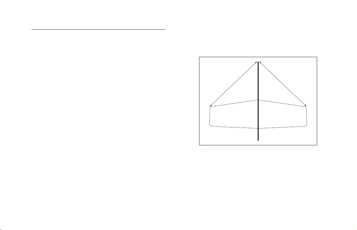
1. Locate the wing and fuselage. Slide the wing
into the fuselage and center it as shown in the
drawing. Use either a ruler or a ruler and string
to ensure the dimensions are the same as shown.
Hint: Use the opening in the bottom of the wing
for the servos to help in alignment.
13
Page 14
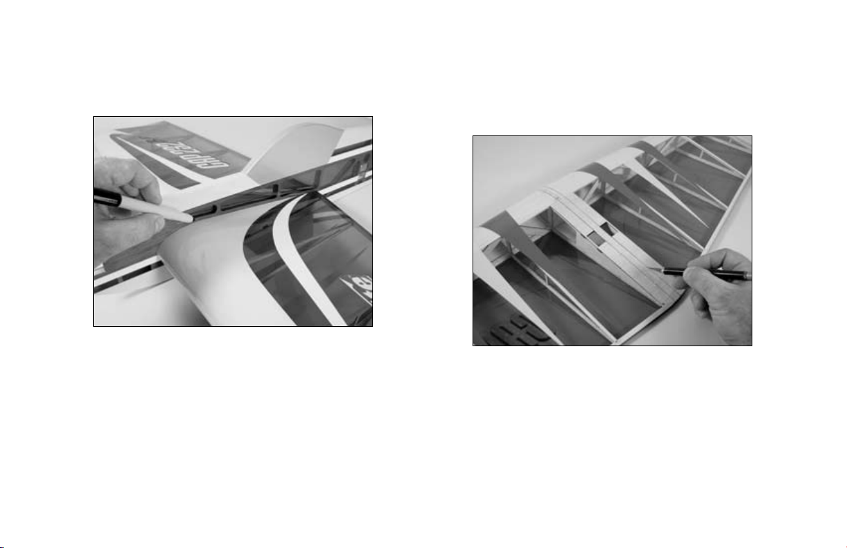
2. Use a felt-tipped pen to trace the outline
of the fuselage onto the top and bottom of
the wing.
3. Remove the wing and use a hobby knife
with a sharp #11 blade to remove the
covering from the wing 1/16" (1.5mm) inside
the lines drawn.
Important: Do not cut into the underlying wood.
This will weaken the structure and could cause
failure in flight. As an option, you can use a
soldering iron or hot knife with light pressure
to carefully melt the covering and avoid the
potential of cutting into the wood.
14
Page 15

4. Slide the wing back into position in the
90º 90º
fuselage. Check to make sure the wing is
perpendicular (90°) to the fuselage as shown.
Lightly sand the opening in the fuselage if
necessary to make any adjustments.
5. Wick thin CA into the joint between the
wing and fuselage. Make sure to apply CA
to left, right, top and bottom to guarantee the
wing is glued securely.
Note: Avoid using a CA accelerator to allow the
CA to wick well into the wood of the fuselage and
wing. This will provide the best bond between the
two items.
15
Page 16

Parallel
6. Slide the stabilizer into position in the fuselage.
A=A
B=B
BB
AA
Check that it has been centered using the
drawing as a reference.
7. Check that the stabilizer and wing are parallel
to each other. Lightly sand the opening in the
fuselage to correct any alignment problems.
16
Page 17

8. Follow Steps 2, 3 and 5 to prepare and glue
the stabilizer to the fuselage.
17
Page 18

Hinging
Required Parts
Airframe
CA hinges (17)
Elevator (left and right)
Aileron (left and right)
Rudder
Plywood elevator joiner
Required Tools and Adhesives
Thin CA
T-pins
Straight edge
1. Remove the covering from one elevator to
expose the slot for the plywood elevator joiner.
Slide the joiner into position and check it is
aligned with the front edge of the elevator using
a straight edge. Wick thin CA into the joint
between the joiner and elevator to secure the
joiner in position.
18
Page 19

2. Place a T-pin in the center of three hinges. 3. Slide the hinges into the pre-cut slots of
the elevator.
19
Page 20

4. Slide the hinges and elevator into position
on the stabilizer. Align the end of the elevator
with the end of the stabilizer. Remove the
T-pins to position the elevator as close to the
stabilizer as possible, eliminating the gap
between the two. Saturate each hinge, top
and bottom, with thin CA.
Note: Do not use CA accelerator on the
hinges. The CA must be allowed to soak into
the hinges and surrounding wood to provide
the best bond.
5. Repeat Steps 2 through 4 to install the
remaining elevator. Apply thin CA to the elevator
joiner as well as the hinges.
20
Page 21

6. Hinging the rudder follows the same procedure
as the elevators, except you don’t have to worry
about the elevator joiner. Use three CA hinges
when attaching the rudder to the fin/fuselage.
7. The last step is to hinge the ailerons to the
wing. Each aileron uses four hinges to attach
it to the wing.
21
Page 22

Landing Gear Installation
Required Parts
Assembled airframe
Tail gear wire
Tail wheel, 3/4" (20mm)
Tail wheel retainer
Main gear strut (2)
Main wheel, 1
Wheel spacer (2)
4-40 nut (4)
4-40 x 1/2" machine screw (2)
2mm x 15mm machine screw (2)
2mm nut (2)
Required Tools and Adhesives
Pliers
Phillips screwdriver (small)
Hex wrench: 3/32"
Thin CA
6-minute epoxy
Threadlock
7
/8" (48mm) (2)
1. Locate the tail gear wire. Use 6-minute
epoxy to glue the wire into the slot in the bottom
of the rudder.
22
Page 23

2. Slide the tail wheel onto the wire once the
epoxy has fully cured. Use the tail wheel retainer
to keep the wheel in position. A drop of thin CA
on the retainer will secure it to the wire. Make
sure not to get CA into the tail wheel, preventing
it from rotating.
3. Slide a wheel spacer onto one of the
4-40 x 1/2" machine screws. Slide the screw
into the wheel and thread a 4-40 nut onto
the screw.
23
Page 24

4. Slide the wheel assembly into the 7/64"
hole in the landing gear, making sure the
wheel will be on the correct side of the
gear. Use a 3/32" hex wrench in the screw to
prevent it from rotating while installing the
4-40 nut on the inside of the landing gear.
Use a drop of thin CA or threadlock on the
nut to prevent it from vibrating loose.
6. Attach the main gear to the fuselage using two
2mm x 15mm machine screws and the two 2mm
nuts. Use a drop of thin CA or threadlock on the
nuts to prevent them from vibrating loose.
5. Repeat Steps 3 and 4 for the remaining wheel.
24
Page 25

Radio Installation
Required Parts
Assembled airframe
Carbon linkage (long), 9
Carbon linkage (medium) 8
Carbon linkage (short) (2) 5
Control horn w/backplate (4)
Nylon clevis (4)
Pushrod control connector w/hardware (4)
Servos w/hardware (4)
3D length servo arms (4)
Radio system w/receiver
Required Tools and Adhesives
Phillips screwdriver (small)
Felt-tipped pen
Drill
Drill bit: 1/16" (1.5mm), 5/64" (2mm)
Hook and loop tape
Hobby knife (#11 blade)
7
/8" (250mm)
1
/2" (215mm)
1
/2" (140mm)
1. Remove the arms from your four servos. Install
two servos into the openings on the bottom of
the wing using the hardware provided with the
servos. Make sure to position the output of the
servo toward the front of the plane, and to have
the servo leads accessible from the bottom of
the airplane. Pre-drill the holes for the servo
mounting screws using a drill and 1/16" (1.5mm)
drill bit.
25
Page 26
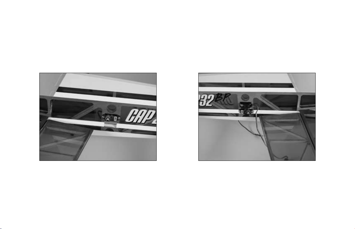
2. The elevator servo is installed in the upper
hole in the fuselage using the hardware provided
with your servo. Pre-drill the holes for the servo
mounting screws using a drill and 1/16" (1.5mm)
drill bit. The output of the servo will be on the left
side facing the front of the plane.
3. The rudder servo is installed in the lower hole
using the hardware provided with your servo.
Pre-drill the holes for the servo mounting screws
using a drill and 1/16" (1.5mm) drill bit. The
output for the rudder servo will be opposite the
elevator servo facing the front of the plane.
26
Page 27

4. Secure the receiver to the fuselage under
the wing using hook and loop tape. Route the
antenna wires according to the manual provided
with your radio system. Plug the servos into the
appropriate positions in the receiver.
Note: Make sure all the wires are neatly taped
to the fuselage to prevent them from getting
entangled with the linkages.
5. Position a control horn on the aileron. The
horn will have the holes for the clevis in line
with the aileron hinge line, and fairly close to
the outer edge of the balsa. Mark the location
for the two horn posts using a felt-tipped pen.
27
Page 28

6. Drill the locations for the horn posts using
a 5/64" (2mm) drill bit.
7. Slide the control horn into the holes
from the bottom of the aileron. Apply a
few drops of thin CA to the posts from the
top of the aileron. Slide the control horn
backplate into position, making sure the
horn is solidly secured. Apply a couple drops
of thin CA where the posts protrude through
the backplate.
28
Page 29

8. Attach a pushrod control connector to a
long 3D servo horn. Remove the remaining
arm using a hobby knife or side cutters.
9. Turn the radio system on and center all
the trims and sticks. Also make sure you
are starting with a clean program if using a
programmable radio. Check the operation of
the servos at this time.
29
Page 30

10. With the radio system on, attach the servo
horn to the aileron servo.
11. Attach a nylon clevis to the outer hole
of the control horn. Slide the short 5
(140mm) pushrod through the connector
on the servo, then into the nylon clevis.
The pushrod should protrude about 1/16"
(1.5mm) into the forks of the clevis. Use a
couple drops of thin CA to glue the clevis to
the pushrod. Be careful not to accidentally
glue the clevis to the control horn.
1
/2"
30
Page 31

12. With the radio system still on, physically
center the aileron. Use the screw from the
pushrod control connector to secure the
pushrod to the connector.
13. Repeat Steps 5 through 12 for the remaining
aileron servo.
31
Page 32

14. The installation of the elevator linkage follows
the same procedure as the aileron linkage. The
only difference is you will be using the medium
1
8
/2" (215mm) length carbon pushrod linkage
during assembly.
15. The last linkage to install is for operating
the rudder. The long 9
pushrod is used for the rudder.
7
/8" (250mm) carbon
32
Page 33

Power System Installation
Required Parts
Assembled airframe
Motor offset shim (2)
Stick mount w/hardware
Brushless motor
20-Amp Brushless ESC (EFLA311B)
910–1320mAh 3-Cell 11.1V Li-Po (THP13203SPL or
THP9103SJPL)
11 x 3.8 Electric Prop (APC11038SF)
EC3 Device & Battery Connector, Male/Female
(EFLAEC303)
Required Tools and Adhesives
Razor saw
Medium CA
Ruler
Hook and loop tape
Drill
Drill bit: 1/16" (1.5mm)
Note: The following steps show the installation
procedures using our E-flite Outrunner BL motor.
You can use an Inrunner motor with a gearbox
as an alternative setup.
1. Mount your particular motor to the stick
type mount using the hardware provided with
the mount.
33
Page 34

2. Cut the motor stick to a length of 7/8" (22mm)
as shown when using the Park 450 motor.
Note: If you are using a park 400, you can use
the same measurement as the Park 450, or cut
the motor stick to a length of 1
position the propeller in the same location as
the Park 450. Either way, you will have plenty
of clearance between the propeller and front of
the fuselage.
1
/8" (28mm) to
3. Use medium CA to glue the two motor offset
shims to the sides of the motor stick. This is
necessary to provide the correct thrust angle for
the motor. Make sure the thin end on the left shim
is towards the front, and the shim on the right has
the thick end of the shim towards the front.
Note: The left and right of the aircraft are
as viewed while sitting in the pilot seat. The
photo above shows a view of the right side
of the fuselage.
34
Page 35

4. Slide the motor mount onto the motor stick. Use
a drill and 1/16" (1.5mm) drill bit to drill a pilot
hole for the screw into the motor stick. Use the
1.5mm x 10mm screw to secure the mount to the
motor stick.
Note: Check that your motor has right
thrust. The motor will be angled towards
the right when viewed from the top of the
aircraft as shown.
Important Information About Your Brushless ESC
Make sure your ESC brake is programmed
to Off. Also, be sure to use an ESC with the
proper 9V cutoff when using 3-cell Li-Po packs,
or 6V cutoff when using 2-cell Li-Po packs.
35
Page 36

5. Solder any necessary connectors onto the
speed control for the motor and battery. Plug the
motor into the speed control. Attach the speed
control to the fuselage using hook and loop tape.
Plug the speed control into the throttle port of
your receiver.
6. Attach the battery to the side of the fuselage
using hook and loop tape. The exact position of
the battery can be changed forward or back,
depending on what is necessary to achieve the
correct center of gravity. Turn on the radio system
and plug the battery into the speed control.
Use the throttle to check that the motor
rotates counterclockwise when viewed from the
front. If not, follow the directions included with
your speed control to change the direction of the
motor rotation.
36
Page 37

Note: Never check the motor rotation on
the bench with the propeller installed. The
plane could move and cause serious injury.
Always check the motor without the propeller
to avoid injury.
Important Information About Your Propeller
It is also very important to check to be sure the
propeller is balanced before installing onto the
shaft. An unbalanced propeller may strip the
gears or cause poor flight characteristics.
Note: If it is necessary to enlarge the hole in the
propeller, make sure to check the balance of the
propeller afterwards.
7. Attach the propeller using the adapter included
with the motor.
37
Page 38

Control Throws
1. Turn on the transmitter and receiver of your
Cap 232 BP. Check the movement of the rudder using
the transmitter. When the stick is moved right, the
rudder should also move right. Reverse the direction of
the servo at the transmitter if necessary.
2. Check the movement of the elevator with the radio
system. Moving the elevator stick down will make the
airplane elevator move up.
3. Use a ruler to adjust the throw of the elevator,
ailerons and rudder. Adjust the position of the
pushrod at the control horn to achieve the
following measurements when moving the sticks
to their endpoints.
Ailerons
Low Rate: 1
High Rate: 1
1
/4" (32mm) with 20% Expo (Up/Down)
3
/4" (45mm) with 43% Expo (Up/Down)
Elevator
Low Rate: 2" (50mm) with 20% Expo (Up/Down)
High Rate: 3" (75mm) with 49% Expo (Up/Down)
Rudder
3" (75mm) (Left/Right)
38
Page 39

Center of Gravity
Range Test Your Radio
An important part of preparing the aircraft for flight is
properly balancing the model.
Caution: Do not inadvertently skip this step!
The recommended Center of Gravity (CG) location for the
Cap 232 BP is 4
the wing against the fuselage.
3
/4" (120mm) behind the leading edge of
1. Before each flying session, be sure to range
check your radio. This is accomplished by turning
on your transmitter with the antenna collapsed. Turn
on the receiver in your airplane. With your airplane
on the ground and the engine running, you should
be able to walk 30 paces (approximately 100 feet)
away from your airplane and still have complete
control of all functions.
If not, don’t attempt to fly! Have your radio equipment
checked out by the manufacturer.
2. Double-check that all controls (aileron, elevator,
rudder and throttle) move in the correct direction.
3. Be sure that your transmitter batteries are fully
charged, per the instructions included with your radio.
39
Page 40

Preflight
Check Your Radio
Before going to the field, be sure that your batteries are
fully charged per the instructions included with your radio.
Charge both the transmitter and receiver pack for your
airplane. Use the recommended charger supplied with
your particular radio system, following the instructions
provided with the radio. In most cases, the radio should be
charged the night before going out flying.
Before each flying session, be sure to range check your
radio. See your radio manual for the recommended
range and instructions for your radio system. Each radio
manufacturer specifies different procedures for their
radio systems. Next, start the motor. With the model
securely anchored, check the range again. The range
test should not be significantly affected. If it is, don’t
attempt to fly! Have your radio equipment checked out
by the manufacturer.
Note: Keep loose items that can get entangled
in the propeller away from the prop. These
include loose clothing, or other objects such as
pencils and screwdrivers. Especially keep your
hands away from the propeller.
Double-check that all controls (aileron, elevator, rudder
and throttle) move in the correct direction.
Check the radio installation and make sure all the
control surfaces are moving correctly (i.e. the correct
direction and with the recommended throws). Test run
the motor and make sure it transitions smoothly from
off to full throttle and back. Also ensure the engine is
installed according to the manufacturer’s instructions,
and it will operate consistently.
Check all the control horns, servo horns, and clevises to
make sure they are secure and in good condition. Replace
any items that would be considered questionable. Failure
of any of these components in flight would mean the loss
of your aircraft.
40
Page 41

Flying Your Cap 232 BP
Flying the Cap 232 BP is about as fun as it can get at
the park. A very light wing loading and extreme control
throws make for some exciting 3D flying. Verify that your
CG is at the correct location as per the manual and that
you have your rates set up to your liking. Verify all control
throws are in the correct direction and the motor spins in
the correct direction as well.
Point the model into the wind and add some throttle trim
until the motor begins to turn. This will be your flight idle.
Now, apply power slowly. You will find the model will
become airborne very quickly and at a low speed. This
model excels at flying slow and easy as well as slow and
extreme. Trim the model for level flight at half throttle. Only
use full throttle for maneuvering. Do not fly this model fast
or at full throttle in level flight. Doing this will result in the
flight controls fluttering and a potential catastrophic failure
of the airframe.
You will find you can adjust the CG to your liking by
moving the battery pack fore or aft on the fuselage. Also
keep the battery on the fuselage mounted high (at least at
wing centerline or above) to help in hovering maneuvers
and harriers.
To land the Cap 232 BP just reduce the throttle to idle and
feed in up elevator until the model settles into a slightly
nose high attitude. Gently fly the model down to the
landing spot with a final flair at touchdown. You will find
the model will have a very short roll out. We hope you
enjoy the Cap 232 BP as much as we do.
Happy landings.
41
Page 42

2006 Official AMA National Model Aircraft Safety Code
GENERAL
1) I will not fly my model aircraft in sanctioned events,
air shows or model flying demonstrations until it has
been proven to be airworthy by having been previously,
successfully flight tested.
2) I will not fly my model higher than approximately 400
feet within 3 miles of an airport without notifying the
airport operator. I will give right-of-way and avoid flying
in the proximity of full-scale aircraft. Where necessary,
an observer shall be utilized to supervise flying to avoid
having models fly in the proximity of full-scale aircraft.
3) Where established, I will abide by the safety rules for
the flying site I use, and I will not willfully or deliberately
fly my models in a careless, reckless and/or dangerous
manner.
4) The maximum takeoff weight of a model is 55 pounds,
except models flown under Experimental Aircraft rules.
5) I will not fly my model unless it is identified with my
name and address or AMA number on or in the model.
(This does not apply to models while being flown indoors.)
6) I will not operate models with metal-bladed propellers
or with gaseous boosts, in which gases other than air
enter their internal combustion engine(s); nor will I operate
models with extremely hazardous fuels such as those
containing tetranitromethane or hydrazine.
RADIO CONTROL
1) I will have completed a successful radio equipment
ground range check before the first flight of a new or
repaired model.
2) I will not fly my model aircraft in the presence of
spectators until I become a qualified flier, unless assisted
by an experienced helper.
3) At all flying sites a straight or curved line(s) must be
established in front of which all flying takes place with the
other side for spectators. Only personnel involved with
flying the aircraft are allowed at or in front of the flight
line. Intentional flying behind the flight line is prohibited.
42
Page 43

2006 Official AMA National Model Aircraft Safety Code
4) I will operate my model using only radio control
frequencies currently allowed by the Federal
Communications Commission. (Only properly licensed
Amateurs are authorized to operate equipment on
Amateur Band frequencies.)
5) Flying sites separated by three miles or more are
considered safe from site-to-site interference, even when
both sites use the same frequencies. Any circumstances
under three miles separation require a frequency
management arrangement, which may be either an
allocation of specific frequencies for each site or testing to
determine that freedom from interference exists. Allocation
plans or interference test reports shall be signed by the
parties involved and provided to AMA Headquarters.
Documents of agreement and reports may exist between
(1) two or more AMA Chartered Clubs, (2) AMA clubs
and individual AMA members not associated with AMA
Clubs, or (3) two or more individual AMA members.
6) For Combat, distance between combat engagement
line and spectator line will be 500 feet per cubic inch of
engine displacement. (Example: .40 engine = 200 feet.);
electric motors will be based on equivalent combustion
engine size. Additional safety requirements will be per the
RC Combat section of the current Competition Regulations.
7) At air shows or model flying demonstrations, a single
straight line must be established, one side of which is for
flying, with the other side for spectators.
8) With the exception of events flown under AMA
Competition rules, after launch, except for pilots or helpers
being used, no powered model may be flown closer than
25 feet to any person.
9) Under no circumstances may a pilot or other person
touch a powered model in flight.
43
Page 44

9766
®
© 2006 Horizon Hobby, Inc.
4105 Fieldstone Road
Champaign, Illinois 61822
(877) 504-0233
horizonhobby.com
E-fliteRC.com
 Loading...