

Page 1

AT-6 25e Texan ARF
Assembly Manual
Specifications
Wingspan: 54 in (1370mm)
Length: 39 in (990mm)
Wing Area: 455 sq in (29.35 sq dm)
Weight w/ Battery: 3.9–4.5 lb (1.8–2.0 kg)
Weight w/o Battery: 3–3.25 oz (1.4–1.5 kg)
Page 2

Table of Contents
Introduction
Specifications ...................................................................... 1
Introduction ......................................................................... 2
Using the Manual ................................................................ 2
Contents of Kit/Parts Layout ................................................. 3
Required Radio Equipment ................................................... 3
Important Information About Motor Selection ........................ 4
Outrunner Setup .................................................................. 4
Optional Accessories ........................................................... 4
Required Tools and Adhesives .............................................. 4
Notes Regarding Servos and ESC ........................................ 5
Note on Lithium Polymer Batteries ........................................ 5
Warning ............................................................................. 5
Warranty Information ...................................................... 5–7
Safety, Precautions, and Warnings ....................................... 7
Stabilizer Installation ........................................................... 8
Motor Installation .............................................................. 12
Main Radio Installation ...................................................... 16
Aileron Servo Installation ................................................... 20
Flap Servo Installation ....................................................... 24
Fixed Landing Gear Installation .......................................... 28
Retractable Landing Gear Installation ................................. 30
Power System Installation ................................................... 37
Wing Installation ............................................................... 39
Basic Cockpit and Accessories ........................................... 42
Optional Scale Cockpit Installation ..................................... 44
Control Throws .................................................................. 48
Range Test Your Radio ....................................................... 48
Center of Gravity .............................................................. 49
Preflight ............................................................................ 49
Flying Your AT-6 Texan ARF ............................................... 50
2007 Official AMA National Model Aircraft Safety Code ... 51
E-flite’s AT-6 25e ARF is a superb scale replica of the legendary
“Texan” trainer used by the U.S.—and its allies—from WWII
through the late 1960s. It features a level of scale detail that
is exceptional for an ARF of this size. You get all this realism
without having to spend weeks of building, covering and
painting. Just about everything has been done for you before
you even open the box. All that’s left to do is a few hours of
final assembly and radio installation. When you’re done, you’ll
have a fantastic flying, scale warbird your friends will swear
you scratch-built yourself.
Platinum Series Statement
Our Platinum Series delivers superior, enhanced features and
meticulous attention to detail. The symbol on this kit is your
assurance of excellence and one more way that E-flite brings
you the most advanced electric flight experience.
Using the Manual
This manual is divided into sections to help make assembly
easier to understand, and to provide breaks between each
major section. In addition, check boxes have been placed next
to each step to keep track of each step completed. Steps with
a single circle () are performed once, while steps with two
circles ( ) indicate that the step will require repeating, such
as for a right or left wing panel, two servos, etc.
Remember to take your time and follow the directions.
2 E-flite AT-6 Texan ARF Assembly Manual
Page 3
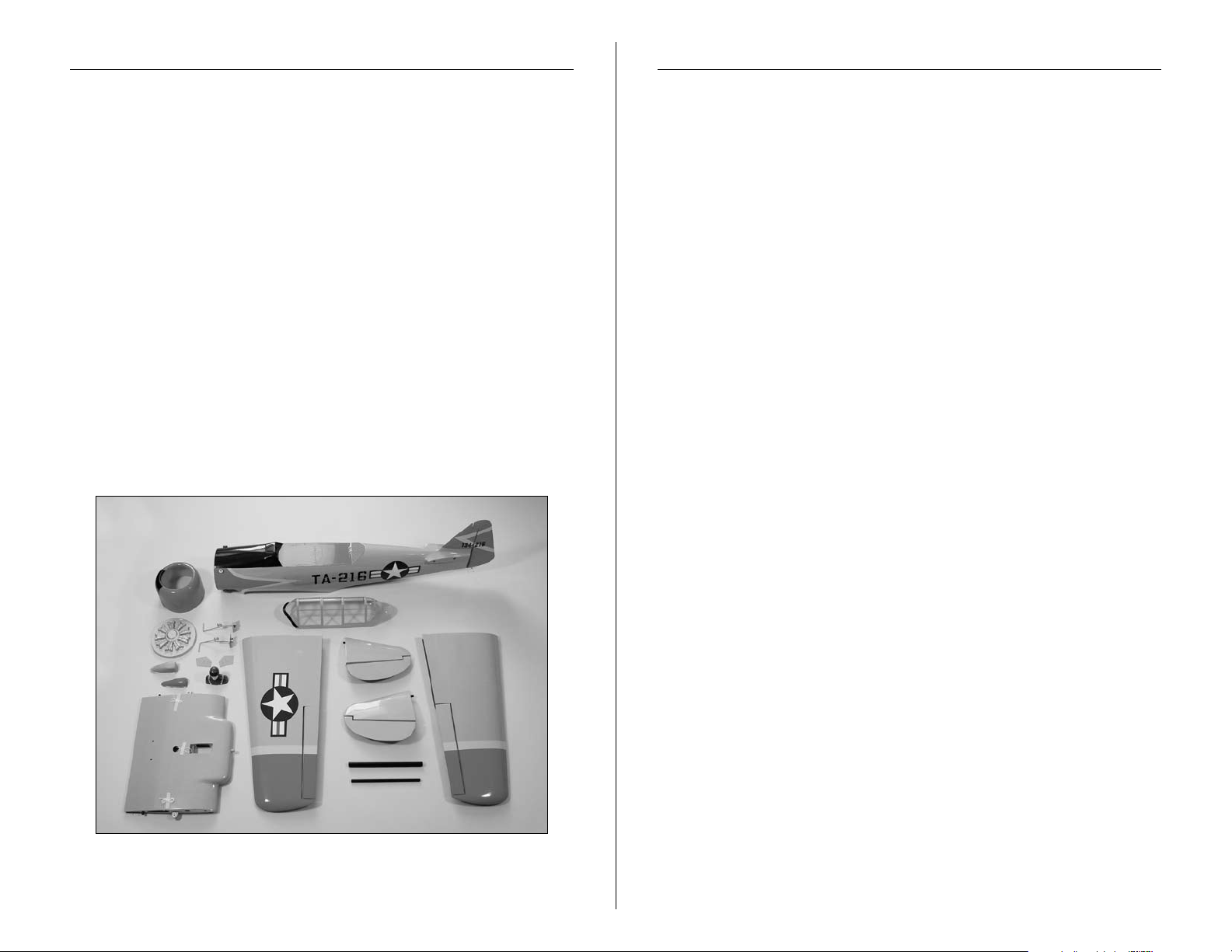
Contents of Kit/Parts Layout
Required Radio Equipment
EFL4501 Wing Set
EFL4501C Main Wing
EFL4501L Left Wing
EFL4501R Right Wing
EFL4502 Fuselage
EFL4503 Tail Set
EFL4503D Rudder
EFL4503L Left Stab
EFL4503R Right Stab
EFL4504 Landing Gear
EFL4505 Cowling
EFL4506 Canopy
EFL4507 Pushrod Set
EFL4508 Battery Hatch
EFL4509 Wing Tube
EFL4510 Stab Tube
EFL4511 Air Inlet Scoop Set
EFLA150 Pilot Figure
You will need a minimum 6-channel transmitter (for proper
mixing and dual rate capabilities), crystals, micro receiver, and
four micro servos. You can choose to purchase a complete radio
system that includes all of these items or, if you are using an
existing transmitter, just purchase the other required equipment
separately. We recommend the crystal-free, interference-free
™
Spektrum
own transmitter, we recommend the JR SPORT
DX7 2.4GHz DSM® 7-channel system. If using your
™
MC35 Micro
servos.
If you own the Spektrum DX7 radio, just add the AR7000
™
DSM2
7-channel receiver and seven of our JR SPORT MC35
Micro servos.
Complete Radio System
SPM2710 DX7 DSM 7CH system
Or Purchase Separately
Or Purchase Separately
JRPR720UL UltraLite 7-Channel ScanSelect
FM Receiver (72MHz)
JRP790UL UltraLite 7-Channel ScanSelect
PCM Receiver (72MHz)
Or
SPMAR6200 AR6200 DSM2 6-Channel Receiver Ultralite
(for DX7 only)
Or
SPM6070 AR7000 DSM2 7CH Rx (for DX7 only)
And
JSP20030 MC35 Micro Servo (7)
JSP98100 3-inch Servo Extension (3)
JSP98110 6-inch Servo Extension (5)
JSP98020 Y-Harness (3)
JSP20080 RT88 retract Servo
Spektrum is used with permission of
Bachmann Industries, Inc.
3E-flite AT-6 Texan ARF Assembly Manual
Page 4

Important Information About
Optional Accessories
Motor Selection
We recommend the E-flite® Power 25 Brushless Outrunner,
870Kv (EFLM4025A) for sport performance.
Outrunner Setup
EFLM4025A Power 25 BL Outrunner, 870Kv
EFLA1060 60-Amp Brushless ESC
THP42003S2PPL 4200mAh 3-Cell 11.1V Li-Po
APC12080E 12 x 8 Electric Prop
EFLAEC303 EC3 Device & Battery Connector,
Male/Female
EFLC3005 Celectra 1- to 3-Cell Li-Po Charger
EFLA110 Power Meter
EFL4515 Robart AT-6 Retracts
EFL4512 Cockpit kit
EFLA150 Military Pilot bust
Required Tools and Adhesives
Tools & Equipment
EFLA250 Park Flyer Tool Assortment, 5-piece
Or Purchase Separately
EFLA257 Screwdriver, #1 and #2 Phillips
(or included with EFLA250)
EFLA251 Hex Wrench: 3/32-inch (or included
with EFLA250)
6-minute epoxy
Canopy glue
Card stock
Covering iron
Drill
Drill bit: 1/16-inch (1.5mm), 5/64-inch (2mm), 1/8-inch (3mm)
Felt-tipped pen
File
Flat blade screwdriver
Hobby knife (#11 blade)
Low-tack tape
Medium CA
Pencil
Phillips screwdriver: #1, #2
Pin drill
Pliers
Rotary tool w/sanding drum
Ruler
Sandpaper
Side cutters
Thin CA
Threadlock
4 E-flite AT-6 Texan ARF Assembly Manual
Page 5

Notes Regarding Servos and ESC
WARNING: Use of servos other than those we recommend may
overload the BEC of the recommended Electronic Speed Control
(ESC). We suggest the use of only the servos we recommend
when utilizing the recommended ESC’s BEC, or the use of a
separate BEC (like the UBEC) or receiver battery pack when
using other servos.
Note on Lithium Polymer Batteries
Lithium Polymer batteries are significantly more
volatile than alkaline or Ni-Cd/Ni-MH batteries used
in RC applications. All manufacturer’s instructions
and warnings must be followed closely. Mishandling
of Li-Po batteries can result in fire. Always follow the
manufacturer’s instructions when disposing of Lithium
Polymer batteries.
Warning
An RC aircraft is not a toy! If misused, it can cause serious
bodily harm and damage to property. Fly only in open areas,
preferably at AMA (Academy of Model Aeronautics) approved
flying sites, following all instructions included with your radio.
Keep loose items that can get entangled in the propeller away
from the prop, including loose clothing, or other objects such as
pencils and screwdrivers. Especially keep your hands away from
the propeller.
Warranty Period
Limited Warranty
(a) This warranty is limited to the original Purchaser
("Purchaser") and is not transferable. REPAIR OR REPLACEMENT
AS PROVIDED UNDER THIS WARRANTY IS THE EXCLUSIVE
REMEDY OF THE PURCHASER. This warranty covers only those
Products purchased from an authorized Horizon dealer. Third
party transactions are not covered by this warranty. Proof of
purchase is required for warranty claims. Further, Horizon
reserves the right to change or modify this warranty without
notice and disclaims all other warranties, express or implied.
(b) Limitations- HORIZON MAKES NO WARRANTY OR
REPRESENTATION, EXPRESS OR IMPLIED, ABOUT NONINFRINGEMENT, MERCHANTABILITY OR FITNESS FOR A
PARTICULAR PURPOSE OF THE PRODUCT. THE PURCHASER
ACKNOWLEDGES THAT THEY ALONE HAVE DETERMINED
THAT THE PRODUCT WILL SUITABLY MEET THE REQUIREMENTS
OF THE PURCHASER’S INTENDED USE.
(c) Purchaser Remedy- Horizon's sole obligation hereunder
shall be that Horizon will, at its option, (i) repair or (ii)
replace, any Product determined by Horizon to be defective.
In the event of a defect, these are the Purchaser's exclusive
remedies. Horizon reserves the right to inspect any and all
equipment involved in a warranty claim. Repair or replacement
decisions are at the sole discretion of Horizon. This warranty
does not cover cosmetic damage or damage due to acts of
God, accident, misuse, abuse, negligence, commercial use,
or modification of or to any part of the Product. This warranty
does not cover damage due to improper installation, operation,
maintenance, or attempted repair by anyone other than
Horizon. Return of any goods by Purchaser must be approved
in writing by Horizon before shipment.
Horizon Hobby, Inc., (Horizon) warranties that the Products
purchased (the “Product”) will be free from defects in materials
and workmanship at the date of purchase by the Purchaser.
5E-flite AT-6 Texan ARF Assembly Manual
Page 6

Damage Limits
Questions, Assistance, and Repairs
HORIZON SHALL NOT BE LIABLE FOR SPECIAL, INDIRECT
OR CONSEQUENTIAL DAMAGES, LOSS OF PROFITS OR
PRODUCTION OR COMMERCIAL LOSS IN ANY WAY
CONNECTED WITH THE PRODUCT, WHETHER SUCH CLAIM IS
BASED IN CONTRACT, WARRANTY, NEGLIGENCE, OR STRICT
LIABILITY. Further, in no event shall the liability of Horizon
exceed the individual price of the Product on which liability
is asserted. As Horizon has no control over use, setup, final
assembly, modification or misuse, no liability shall be assumed
nor accepted for any resulting damage or injury. By the act of
use, setup or assembly, the user accepts all resulting liability.
If you as the Purchaser or user are not prepared to accept the
liability associated with the use of this Product, you are advised
to return this Product immediately in new and unused condition
to the place of purchase.
Law: These Terms are governed by Illinois law (without regard to
conflict of law principals).
Safety Precautions
This is a sophisticated hobby Product and not a toy. It must be
operated with caution and common sense and requires some
basic mechanical ability. Failure to operate this Product in a safe
and responsible manner could result in injury or damage to the
Product or other property. This Product is not intended for use
by children without direct adult supervision. The Product manual
contains instructions for safety, operation and maintenance. It is
essential to read and follow all the instructions and warnings in
the manual, prior to assembly, setup or use, in order to operate
correctly and avoid damage or injury.
Your local hobby store and/or place of purchase cannot provide
warranty support or repair. Once assembly, setup or use of the
Product has been started, you must contact Horizon directly.
This will enable Horizon to better answer your questions and
service you in the event that you may need any assistance.
For questions or assistance, please direct your email to
productsupport@horizonhobby.com, or call 877.504.0233 toll
free to speak to a service technician.
Inspection or Repairs
If this Product needs to be inspected or repaired, please call for
a Return Merchandise Authorization (RMA). Pack the Product
securely using a shipping carton. Please note that original boxes
may be included, but are not designed to withstand the rigors
of shipping without additional protection. Ship via a carrier that
provides tracking and insurance for lost or damaged parcels, as
Horizon is not responsible for merchandise until it arrives and
is accepted at our facility. A Service Repair Request is available
at www.horizonhobby.com on the “Support” tab. If you do not
have internet access, please include a letter with your complete
name, street address, email address and phone number where
you can be reached during business days, your RMA number,
a list of the included items, method of payment for any nonwarranty expenses and a brief summary of the problem.
Your original sales receipt must also be included for warranty
consideration. Be sure your name, address, and RMA number
are clearly written on the outside of the shipping carton.
Warranty Inspection and Repairs
To receive warranty service, you must include your original
sales receipt verifying the proof-of-purchase date. Provided
warranty conditions have been met, your Product will be
repaired or replaced free of charge. Repair or replacement
decisions are at the sole discretion of Horizon Hobby.
6 E-flite AT-6 Texan ARF Assembly Manual
Page 7

Non-Warranty Repairs
Safety, Precautions, and Warnings
Should your repair not be covered by warranty the repair
will be completed and payment will be required without
notification or estimate of the expense unless the expense
exceeds 50% of the retail purchase cost. By submitting the item
for repair you are agreeing to payment of the repair without
notification. Repair estimates are available upon request. You
must include this request with your repair. Non-warranty repair
estimates will be billed a minimum of ½ hour of labor. In
addition you will be billed for return freight. Please advise us
of your preferred method of payment. Horizon accepts money
orders and cashiers checks, as well as Visa, MasterCard,
American Express, and Discover cards. If you choose to pay
by credit card, please include your credit card number and
expiration date. Any repair left unpaid or unclaimed after 90
days will be considered abandoned and will be disposed of
accordingly. Please note: non-warranty repair is only available
on electronics and model engines.
Electronics and engines requiring inspection or repair should be
shipped to the following address:
Horizon Service Center
4105 Fieldstone Road
Champaign, Illinois 61822
All other Products requiring warranty inspection or repair should
be shipped to the following address:
Horizon Product Support
4105 Fieldstone Road
Champaign, Illinois 61822
Please call 877-504-0233 with any questions or concerns
regarding this product or warranty.
As the user of this product, you are solely responsible for
operating it in a manner that does not endanger yourself
and others or result in damage to the product or the property
of others.
Carefully follow the directions and warnings for this and any
optional support equipment (chargers, rechargeable battery
packs, etc.) that you use.
This model is controlled by a radio signal that is subject to
interference from many sources outside your control. This
interference can cause momentary loss of control so it is
necessary to always keep a safe distance in all directions
around your model, as this margin will help to avoid collisions
or injury.
• Always operate your model in an open area away from cars,
traffic, or people.
• Avoid operating your model in the street where injury or
damage can occur.
• Never operate the model out into the street or populated
areas for any reason.
• Never operate your model with low transmitter batteries.
• Carefully follow the directions and warnings for this and any
optional support equipment (chargers, rechargeable battery
packs, etc.) that you use.
• Keep all chemicals, small parts and anything electrical out of
the reach of children.
• Moisture causes damage to electronics. Avoid water exposure
to all equipment not specifically designed and protected for
this purpose.
7E-flite AT-6 Texan ARF Assembly Manual
Page 8
Stabilizer Installation
Required Parts
Stabilizer (right and left) 3mm x 10mm self-tapping screw
(2)
Stabilizer tube Nylon clevis (3)
Clevis retainer (3) 1-inch (25mm) tail wheel
1/16-inch wheel collar w/setscrew
7
20
/
-inch (530mm) pushrod wire (2)
8
3
/
-inch (553mm) pushrod wire
21
4
Required Tools and Adhesives
Drill Drill bit: 5/64-inch (2mm)
Phillips screwdriver: #1 Threadlock
Hex wrench (included with kit)
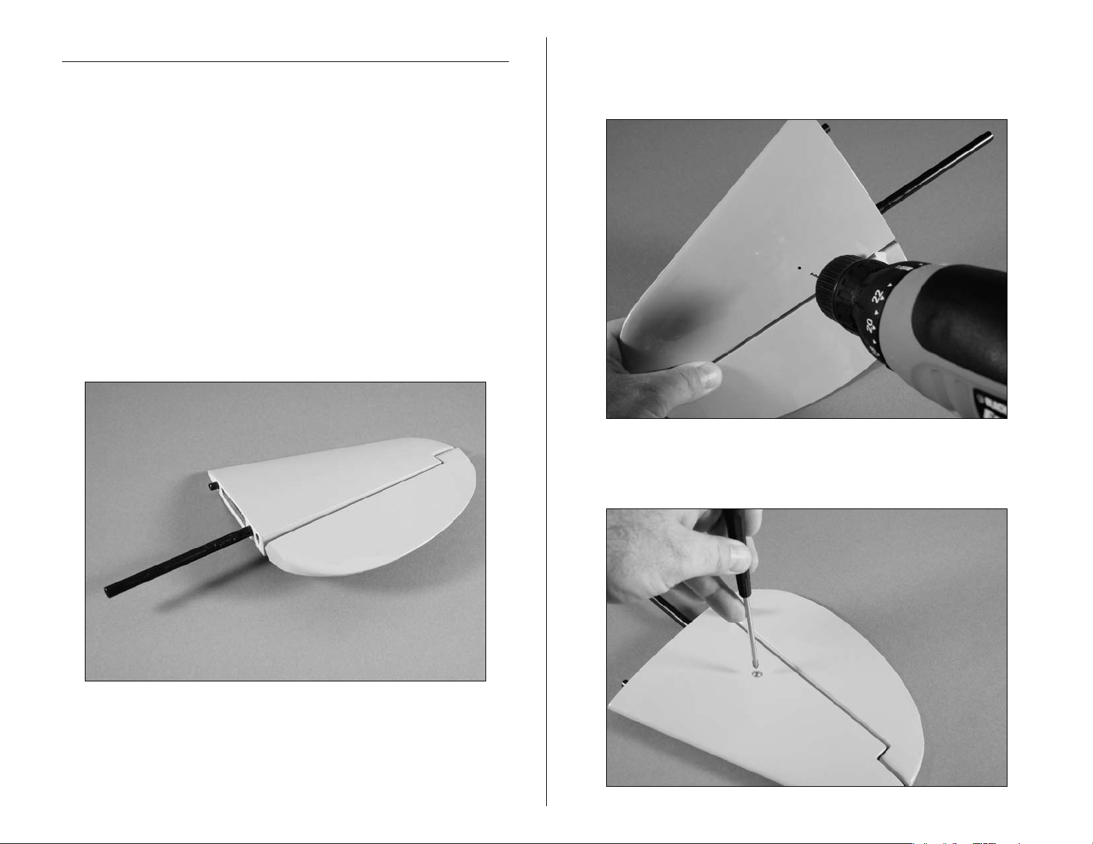
1. Slide the stabilizer tube all the way into the stabilizer.
2. Use a drill and 5/64-inch (2mm) drill bit to drill
through the hole in the bottom of the stabilizer and into
the stabilizer tube.
3. Secure the tube using a 3mm x 10mm self-tapping
screw and #1 Phillips screwdriver.
8 E-flite AT-6 Texan ARF Assembly Manual
Page 9
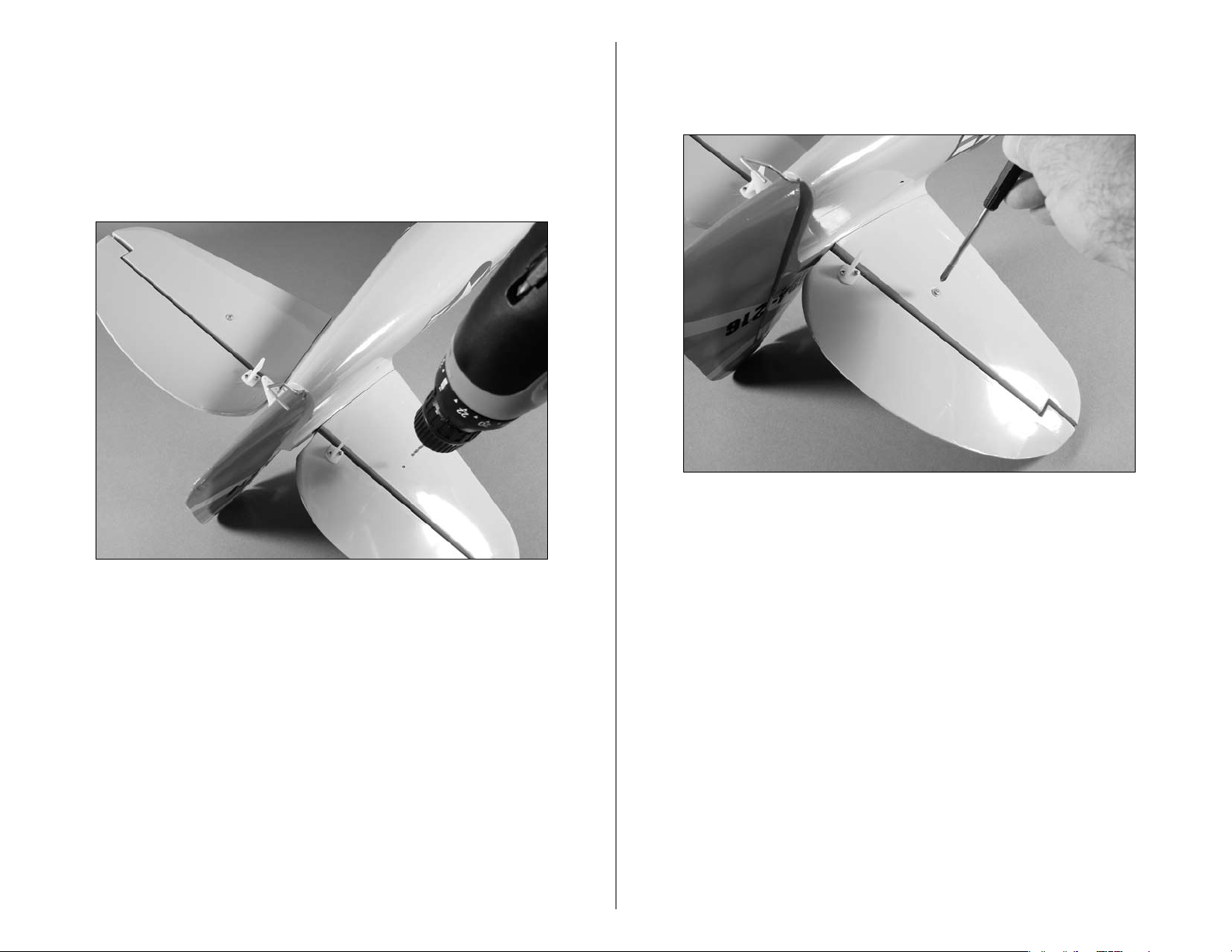
4. Slide the stabilizer and tube in position in the fuselage.
Note the direction of the control horn and that it faces
the bottom of the fuselage. Slide the remaining stabilizer
onto the tube. With both stabilizer halves tight against the
fuselage, use a drill and 5/64-inch (2mm) drill bit to drill
through the hole in the stabilizer and into the stabilizer
tube.
5. Secure the remaining stabilizer onto the tube using
a 3mm x 10mm self-tapping screw and #1 Phillips
screwdriver.
9E-flite AT-6 Texan ARF Assembly Manual
Page 10
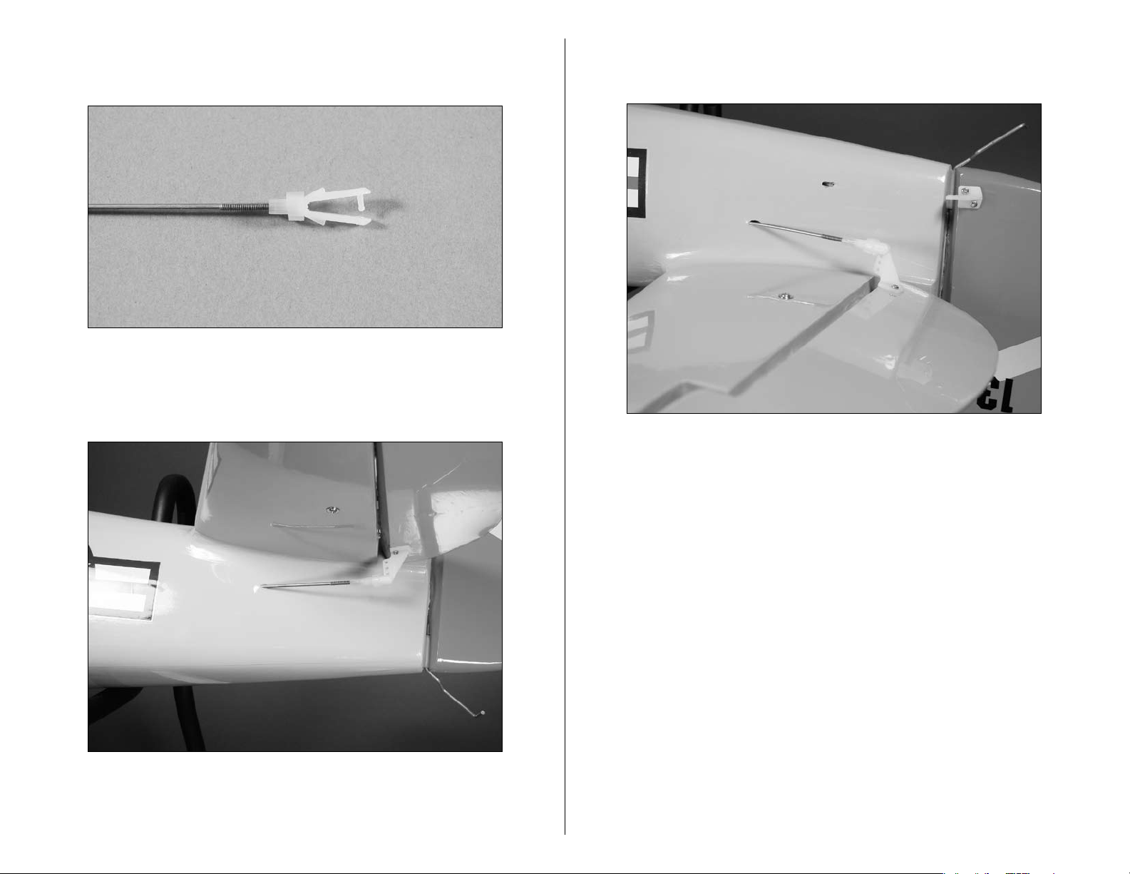
6. Slide a clevis retainer onto a nylon clevis. Thread the
7
/
clevis onto one of the 20
-inch (530mm) pushrod wires.
8
7. Slide the pushrod wire into the opening in the fuselage
that aligns with the stabilizer control horn. Snap the clevis
onto the elevator control horn.
8. Repeat Steps 6 and 7 for the remaining elevator
pushrod installation
10 E-flite AT-6 Texan ARF Assembly Manual
Page 11
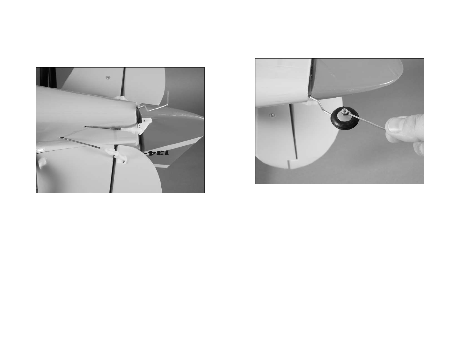
9. Slide a clevis retainer onto a nylon clevis. Thread the
3
/
clevis onto the 21
-inch (553mm) pushrod wire. Slide
4
the pushrod wire into the opening in the fuselage that
aligns with the stabilizer control horn. Snap the clevis
onto the elevator control horn.
10. Slide the tail wheel onto the tail gear wire. Use a
1/16-inch wheel collar., setscrew and the included hex
wrench to secure the wheel. Remember to use threadlock
on the setscrew to prevent it from vibrating loose.
11E-flite AT-6 Texan ARF Assembly Manual
Page 12
Motor Installation
Required Parts
Fuselage Motor w/mount and accessories
#4 washer (4) Cowling
Dummy radial engine Radiator scoop (red)
Propeller
4-40 x 1/2-inch socket head screw (4)
4-40 x 1/4-inch socket head screw (4)
Required Tools and Adhesives
Rotary tool w/sanding drum Ball driver: 3/32-inch
Hobby knife 6-minute epoxy
Card stock Low-tack tape
Felt-tipped pen Pin drill
Drill bit: 1/8-inch (3mm) Threadlock
Medium CA Phillips screwdriver: #2
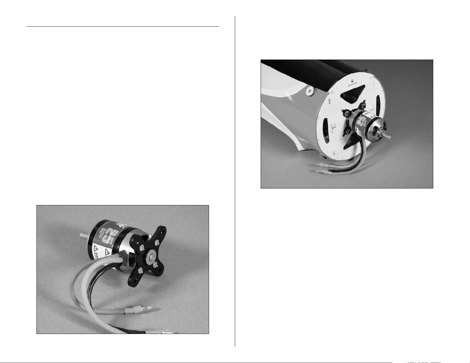
1. Attach the X-Mount to the motor using the screws
provided with the motor and a #2 Phillips screwdriver.
Make sure to use threadlock on all four screws so they do
not vibrate loose.
2. Attach the motor to the firewall using four
4-40 x 1/2-inch socket head screws, four #4 washers
and a 3/32-inch ball driver. Make sure to use threadlock
on the four screws to prevent them from vibrating loose.
Note: The blind nuts in the fuselage for mounting the
motor can be positioned for a variety of motors. Position
them so they are aligned with your particular motor
before mounting it to the firewall.
Note: You may paint your dummy motor to simulate the
engine found in most full size AT-6's. It is better and
easier to paint it at this time before it is installed in the
cowling. Please refer to our Scale Accessories section
beginning on Page 43 for the correct color choices for
the motor.
12 E-flite AT-6 Texan ARF Assembly Manual
Page 13
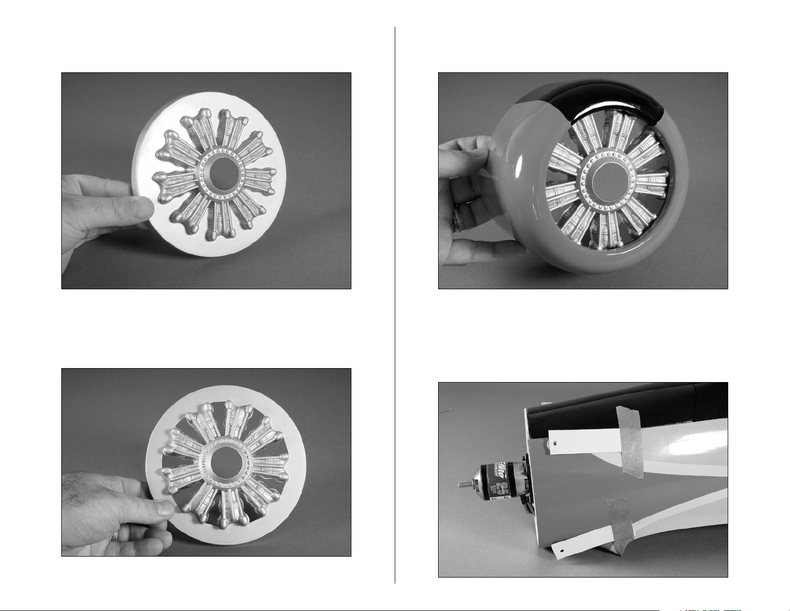
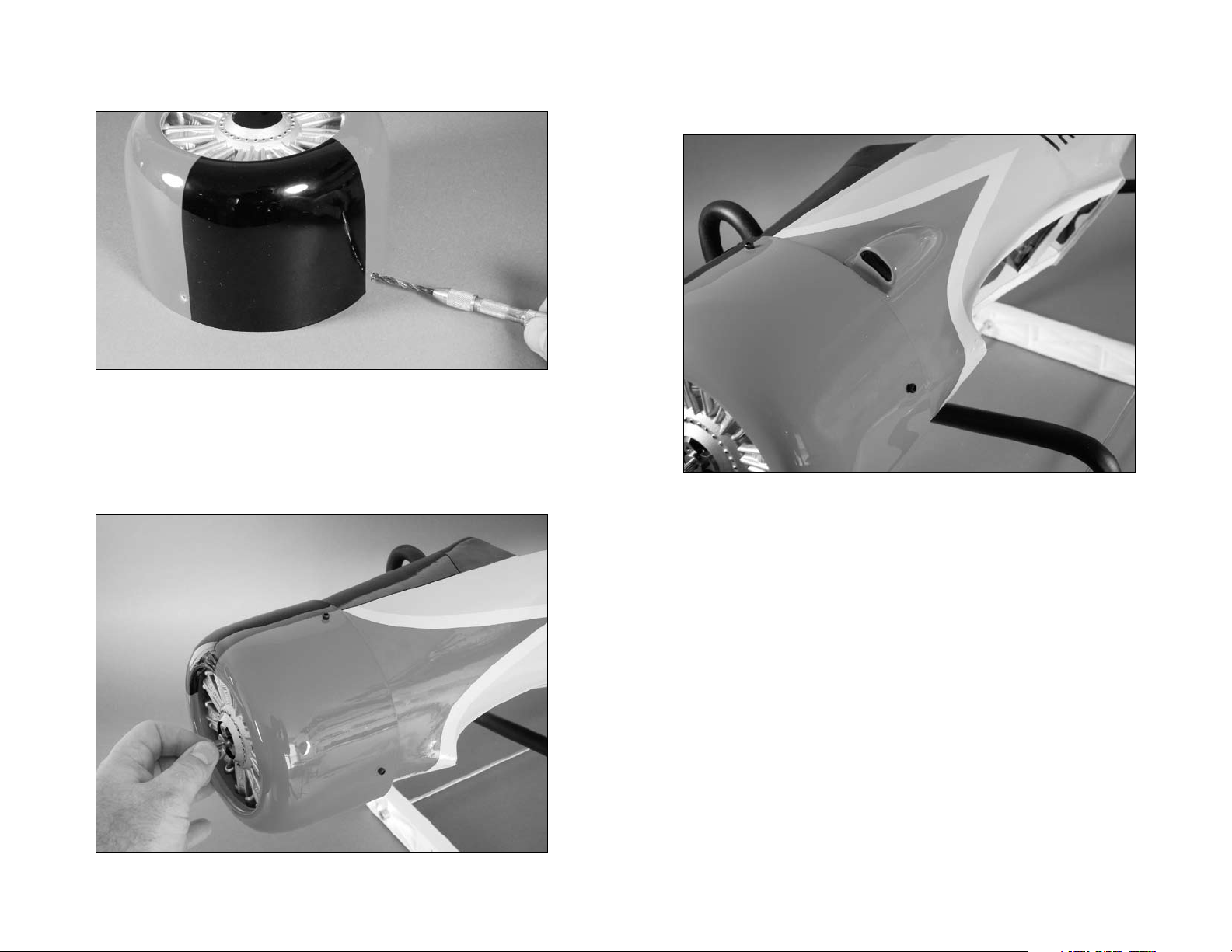
3. Use a hobby knife and rotary tool to remove the area
in the center of the dummy radial engine.
5. Use 6-minute epoxy to glue the dummy radial engine
inside the cowling.
4. Use a hobby knife to remove the area between each
of the cylinders to allow cooling air to pass through the
cowling and over the motor.
6. Cut four strips of card stock. Make a 1/8-inch (3mm)
hole in the end of each strip. Align the hole with the blind
nut and use low-tack tape to hold the card stock to the
fuselage.
13E-flite AT-6 Texan ARF Assembly Manual
Page 14
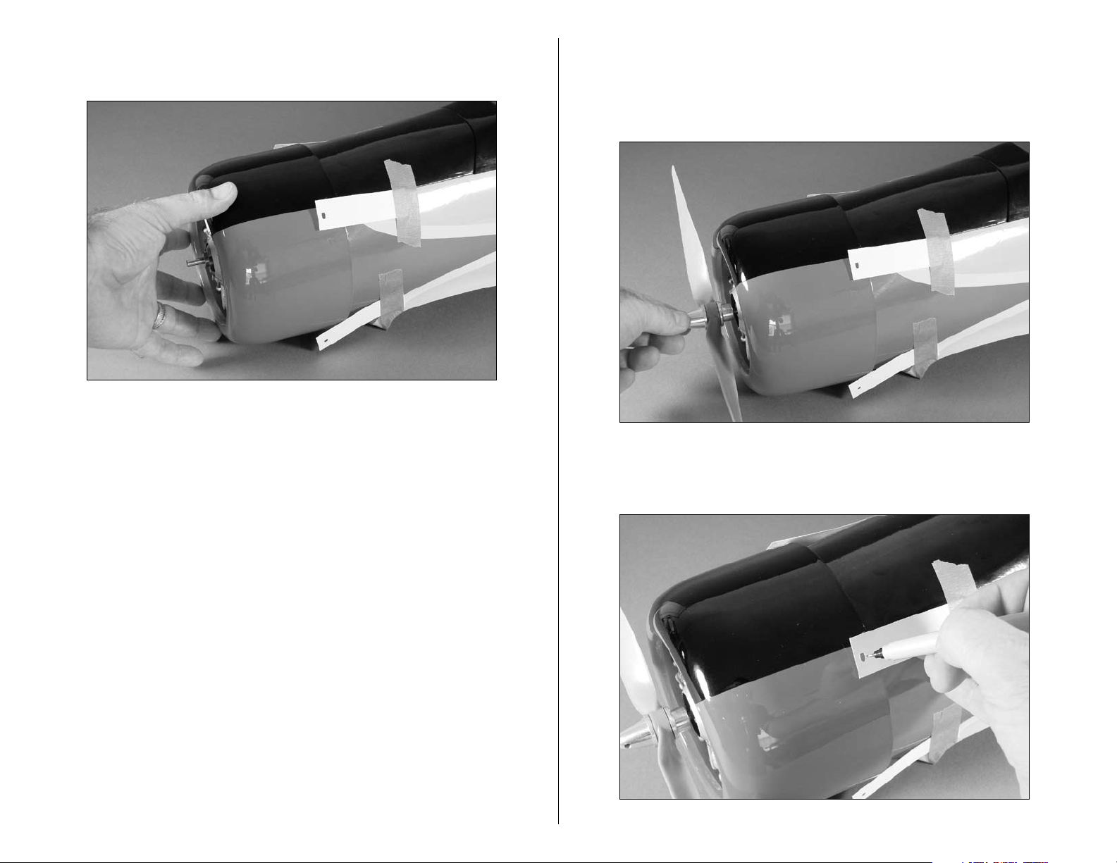
7. Slide the cowling onto the fuselage. The card stock will
be on the outside of the cowling.
Important Information About Your Propeller
It is also very important to check to be sure the
propeller is balanced before installing onto the shaft. An
unbalanced propeller may strip the gears or cause poor
flight characteristics.
8. Slide the propeller and adapter onto the motor shaft.
Position the cowling so it will not be rubbing on the
propeller when the motor is running. Tape the cowling in
position on the fuselage.
9. Use a felt-tipped pen to transfer the locations for the
4-40 socket head screws onto the outside of the cowling.
Note: If it is necessary to enlarge the hole in the
propeller, make sure to check the balance of the
propeller afterwards.
14 E-flite AT-6 Texan ARF Assembly Manual
Page 15
10. Use a pin drill and 1/8-inch (3mm) drill bit to drill
the four holes in the cowling for the mounting screws.
11 Slide the cowling back onto the fuselage and secure
it using four 4-40 x 1/4-inch socket head screws and a
3/32-inch ball driver. Make sure to use threadlock on the
screws to prevent them from vibrating loose.
12. Use medium CA to glue the radiator scoop to the
side of the fuselage behind the cowling. A felt-tipped pen
can be used to color in the scoop to give that open look.
15E-flite AT-6 Texan ARF Assembly Manual
Page 16
Main Radio Installation
Required Parts
Fuselage Receiver
Servo w/hardware (3) Pushrod connector (3)
Hook and loop material
Required Tools and Adhesives
Thin CA Felt-tipped pen
Side cutters Pliers
Pin drill Phillips screwdriver: #1
Drill bit: 1/16-inch (1.5mm), 5/64-inch (2mm)
Note: The installation of the elevator servos will require
either of the following options, as using a standard
Y-harness for the servos will result in the servos moving
the control surfaces in the opposite directions.
Option 1: Use a computer radio to mix the elevator
servos together using two separate channels. Ensure you
use a correct mix in your radio that has an active trim to
trim both elevators in flight.
Option 2: Use a reversing Y-harness (EXRA320) between
the two servos and the receiver.
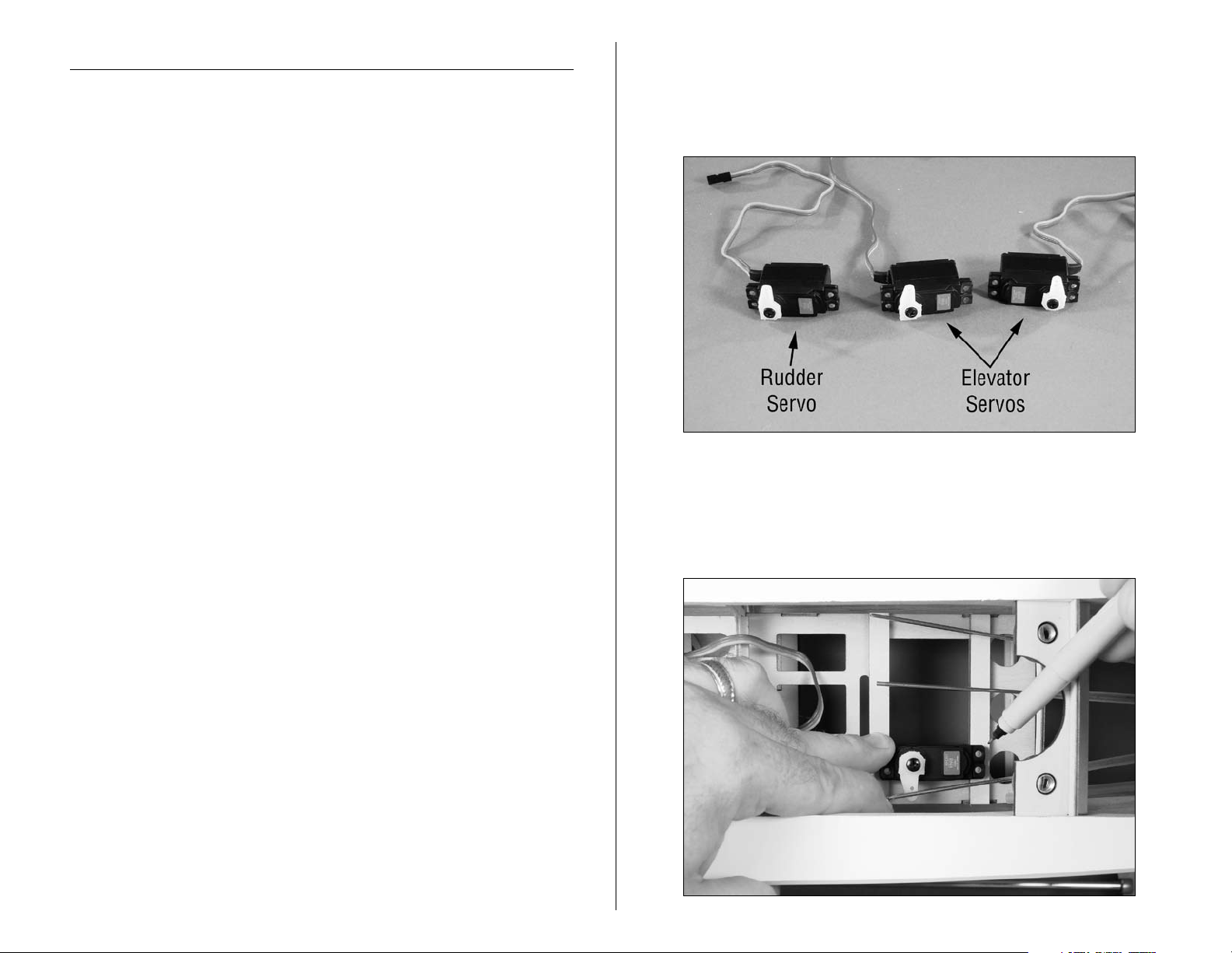
2. Prepare the rudder and elevator servos for installation
by removing any unnecessary arms from the servo horns
as shown using side cutters. Install any grommets and
brass eyelets at this time as well.
3. Position the elevator servo in the fuselage, aligning the
outer hole in the servo arm with the elevator pushrod.
Mark the locations for the servo mounting screws on the
servo mounting rails using a felt-tipped pen.
1. Turn on your radio system and select a new model if
using a computer radio. Make sure all the sub trims have
been set to 0 and no mixing functions are turned on.
Center the trim levers and stick at this time as well. Plug
the servos into the radio system and make sure all servos
operate and are centered as well.
16 E-flite AT-6 Texan ARF Assembly Manual
Page 17

4. Use a pin drill and 1/16-inch (1.5mm) drill bit to drill
the four holes for the servo mounting screws.
5. Apply a few drops of thin CA to each of the
holes drilled in the previous step to harden the
surrounding wood.
6. Mount the servo using the screws provided with the
servo and a #1 Phillips screwdriver.
7. Repeat Steps 3 through 6 to install the remaining
elevator servo and rudder servo.
17E-flite AT-6 Texan ARF Assembly Manual
Page 18

8. Use hook and loop tape to install the receiver in the
fuselage following the manufacturer's instructions. A
tube has been installed inside the fuselage to route the
antenna wire. Do not cut the receiver wire if it extends
excessively outside the fuselage as this will greatly reduce
the range of your radio system.
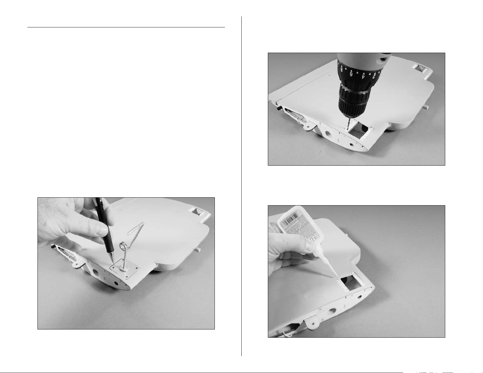
9. Physically center the rudder. Use a felt-tipped pen to
mark the rudder pushrod where it crosses the outer hole
of the rudder servo arm.
10. Remove the rudder pushrod from the fuselage and
make a 90-degree bend in the pushrod at the mark
made in the previous step using pliers. You will also have
to remove the clevis at this time as well to reinstall the
pushrod.
18 E-flite AT-6 Texan ARF Assembly Manual
Page 19

11. Use a 5/64-inch (2mm) drill bit to enlarge the
outer hole in the rudder servo arm. Use a #2 Phillips
screwdriver to remove screw and the arm from the servo.
13. Slide the pushrod back into the pushrod tube and
thread the clevis back onto the pushrod. With the radio
on and the rudder stick and trim centered, secure the
servo arm to the servo. Center the rudder by threading
the clevis in or out as necessary.
12. Slide the bend in the pushrod through the hole in the
servo horn from the topside of the horn. Use a pushrod
connector to secure the pushrod to the horn.
14. Repeat Steps 9 through 13 to connect the two
elevator pushrods to the elevator servos.
19E-flite AT-6 Texan ARF Assembly Manual
Page 20

Aileron Servo Installation
Required Parts
Outer wing panels (right and left) Servo w/hardware (2)
3mm x 10mm self-tapping screw (8) Clevis retainer (2)
1
2
/2-inch (64mm) pushrod wire Clevis (2)
Pushrod connector (2)
6-inch (152mm) servo extension (2)
Servo mounting block
3/4 x 3/8 x 3/8-inch (19 x 9.5 x 9.5mm) (4)
Required Tools and Adhesives
Drill Drill bit: 1/16-inch (1.5mm)
6-minute epoxy Pencil
Phillips screwdriver: #1 Felt-tipped pen
Side cutters Pliers
Thin CA
1. Plug the aileron servos into the radio system and make
sure they operate and are centered as well.
2. Prepare the aileron servos for installation by removing
any unnecessary arms from the servo horns as shown
using side cutters. Install any grommets and brass
eyelets at this time as well. The servos will have the arms
installed opposite of each other as shown in the photo.
3. Position the aileron servo on the servo cover so the
arm is centered lengthwise in the cutout. The arm will
align with the edge of the servo cover as well. Use a
pencil to mark the position of the servo on the cover.
4. Use 6-minute epoxy to glue the servo mounting block
to the servo cover as shown. Allow the epoxy to fully cure
before proceeding.
Note: You will find the servo mounting blocks in your
kit to vary in length from the measurements listed
above. They have been cut to the correct length from
the manufacturer.
20 E-flite AT-6 Texan ARF Assembly Manual
Page 21

5. Position the servo between the servo mounting block.
Use a pencil to mark the locations for the servo mounting
screws on the blocks. The servo should not touch the
cover to prevent it from absorbing vibrations from the
airframe. You may have to notch the servo block to allow
access for the servo wire.
7. Apply a few drops of thin CA to each of the
holes drilled in the previous step to harden the
surrounding wood.
6. Use a drill and 1/16-inch (1.5mm) drill bit to drill the
holes for the servo mounting screws.
8. Use a #1 Phillips screwdriver to install the screws
provided with the servos to attach the servo to the
servo mounting blocks.
21E-flite AT-6 Texan ARF Assembly Manual
Page 22

9. Route the lead from the servo to the opening for the
flap servo. Use four 3mm x 10mm self-tapping screws
and #1 Phillips screwdriver to secure the servo cover to
the wing.
10. Slide a clevis retainer onto a nylon clevis. Thread the
1
/
clevis onto one of the 2
-inch (64mm) pushrod wires.
2
11. Attach the clevis to the control horn of the aileron.
Center the aileron and aileron servo and use a felt-tipped
pen to mark where the pushrod crosses the outer hole of
the servo horn.
22 E-flite AT-6 Texan ARF Assembly Manual
Page 23

12. Use pliers to bend the pushrod 90 degrees at the
mark. Use a pushrod connector to secure the pushrod
wire to the servo arm. Use side cutters to remove any
excess wire.
13. Secure a 6-inch (152mm) servo extension to the
aileron servo lead and route it out the end of the wing
panel.
14. Repeat Steps 3 through 14 for the remaining aileron
servo installation.
23E-flite AT-6 Texan ARF Assembly Manual
Page 24

Flap Servo Installation
Outer wing panels (right and left) Servo w/hardware (2)
3mm x 10mm self-tapping screw (8) Clevis retainer (2)
7
2
/
-inch (73mm) pushrod wire Clevis (2)
8
Pushrod connector (2)
Servo mounting block
3/4 x 3/8 x 3/8-inch (19 x 9.5 x 9.5mm) (4)
Required Tools and Adhesives
Drill Side cutters
6-minute epoxy Pencil
Phillips screwdriver: #1 Felt-tipped pen
Ruler Pliers
Thin CA
Drill bit: 1/16-inch (1.5mm), 5/64-inch (2mm)
1. Plug the flap servos into the radio system and make
sure they operate and are centered as well.
2. Prepare the flap servos for installation by removing
any unnecessary arms from the servo horns as shown.
You will also need to clean up the cuts to prevent any
portion of the removed arm from rubbing against the
servo cover when the servos are installed. Install any
grommets and brass eyelets at this time as well. The
servos will have the arms installed to match each other as
shown in the photo.
Note: The arms are shown in the center position
(which will be the mid flap position) if you are using
three-position flaps. Make sure when using proportional
flaps that the control has been centered before installing
the servo horns.
24 E-flite AT-6 Texan ARF Assembly Manual
Page 25

3. Using a ruler, mark the servo cover as shown
using a pencil.
4. Position the servo so the arm is centered at the
intersection of the lines drawn in the previous step. Use a
pencil to mark the cover for the servo mounting blocks.
5. Use 6-minute epoxy to glue the servo mounting block
to the servo cover as shown. Allow the epoxy to fully cure
before proceeding.
Note: You will find the servo mounting blocks in your
kit to vary in length from the measurements listed
above. They have been cut to the correct length from
the manufacturer.
25E-flite AT-6 Texan ARF Assembly Manual
Page 26

6. Position the servo between the servo mounting blocks.
Use a pencil to mark the locations for the servo mounting
screws on the blocks. The servo should not touch the
cover to prevent it from absorbing vibrations from the
airframe. Use a drill and 1/16-inch (1.5mm) drill bit to
drill the holes for the servo mounting screws. Apply a
few drops of thin CA to each of the holes to harden the
surrounding wood. Use a #1 Phillips screwdriver to install
the screws provided with the servo to attach it to the
servo mounting blocks.
8. Use a pin drill and 5/64-inch (2mm) drill bit to
enlarge the outer hole in the servo arm.
9. Attach the pushrod to the flap servo using a pushrod
connector.
7. Slide a clevis retainer onto a nylon clevis. Thread the
7
/
clevis onto one of the 2
7
/
Measure back 2
-inch (73mm) from the pin in the clevis
8
-inch (73mm) pushrod wires.
8
and mark the pushrod wire. Make a 90-degree bend at
the mark. This will give you a good starting length for the
installation of the flap linkage.
26 E-flite AT-6 Texan ARF Assembly Manual
Page 27

10. Position the flap servo partially in the wing. Connect
the clevis to the flap control horn. Plug the flap servo into
the receiver and power up the radio system.
12. Route the servo lead for the flap to the end of the
wing panel. Use four 3mm x 10mm self-tapping screws
and a #1 Phillips screwdriver to secure the flap servo
cover to the wing.
Note: Do not place or secure the flap servo cover in
position before turning on the radio and checking the
operation of the flap. Doing so could damage the flap
control horn or quite possibly the flap servo. Check the
length of the linkage as follows BEFORE installing the
flap servo cover.
11. With the radio system on, move the control on the
radio to the "Up Flap" position and test fit the cover. If
the cover does not fit without binding the flap or flap
servo, adjust the length of the linkage or change the
end points at the radio system to eliminate any binding.
Repeat the process for "Down Flap" and check that the
full throw is adjusted as noted in the "Control Throw"
section of this manual.
13. Repeat Steps 3 through 12 for the remaining aileron
servo installation.
27E-flite AT-6 Texan ARF Assembly Manual
Page 28
Fixed Landing Gear Installation
Required Parts
Wing center section Landing gear (right and left)
1/8-inch wheel collar (4) 3mm x 4mm machine screw (2)
3mm x 10mm self-tapping screw (8)
Required Tools and Adhesives
Drill Drill bit: 5/64-inch (2mm)
Thin CA File
Phillips screwdriver: #1, #2 Pencil
Threadlock
Note: The main wire struts included with your kit have
been upgraded from the preproduction versions shown
in this manual. Please note your wire struts will have the
main wire yoke offset as per the real AT-6 landing gear.
1. Position the main gear on the rails of the wing center
section. Use a pencil to transfer the locations for the four
mounting screws through the gear and onto the rails.
2. Use a drill and 5/64-inch (2mm) drill bit to drill the
four holes for the mounting screws. Use care not to
accidentally drill through the top of the wing.
3. Apply a few drops of thin CA to each of the holes to
harden the surrounding wood.
28 E-flite AT-6 Texan ARF Assembly Manual
Page 29

4. Use a #2 Phillips screwdriver and four 3mm x 10mm
self-tapping screws to secure the gear in the wing center
section.
5. Use a file to create a flat on the bottom of the landing
gear wire. This provides a place to tighten the screws for
the wheel collars, making them more secure on the wire.
6. Slide one of the wheel collars on the landing gear
wire.
29E-flite AT-6 Texan ARF Assembly Manual
Page 30

7. Slide the wheel onto the landing gear wire, then a
final wheel collar. Use a 3mm x 4mm machine screw and
#1 Phillips screwdriver to secure the wheel collar. Use
threadlock on the screw to prevent it from vibrating loose.
8. Repeat Steps 1 through 7 for the remaining landing
gear and wheel.
Retractable Landing Gear Installation
Required Parts
Wing center section Retract servo w/hardware
Retracts w/hardware Retract linkage (2)
Nylon clevis (2) Clevis retainer (2)
Required Tools and Adhesives
Thin CA Pencil or felt-tipped pen
Covering iron Hobby knife
Drill File
Phillips screwdriver: #1 Threadlock
1/16-inch wheenl collar w/setscrew (2)
Drill bit: 1/16-inch (1.5mm), 5/64-inch (2mm)
Optional Parts
Robart 2
1. Position the retract servo in the opening, guiding
1
/
-inch (63mm) wheels
2
the servo lead under the servo mounting rail at the
rear and out the hole in the wing center section. Mark
the location of the servo mounting screws using a pencil
or felt-tipped pen.
30 E-flite AT-6 Texan ARF Assembly Manual
Page 31

2. Remove the servo and drill the four locations for
the servo mounting screws with a drill and 1/16-inch
(1.5mm) drill bit.
4. Remove the servo horn from the servo. Use a #1
Phillips screwdriver to install the screws provided with the
retract servo to secure it in the wing center section.
3. Apply a few drops of thin CA to each hole to harden
the surrounding wood.
5. Using a hobby knife, cut a cross in the covering over
the opening for the wheel. Use a covering iron to seal
the covering tight against the wing before removing the
covering.
31E-flite AT-6 Texan ARF Assembly Manual
Page 32

6. Remove the covering to expose the entire opening for
the retract.
Hint: Trim the covering about 1/16-inch (1.5mm) from
the inside edge of the opening and use a covering iron
to seal the covering into the opening for a super clean
retract installation.
7. Position the main gear on the rails of the wing center
section. Use a pencil to transfer the locations for the four
mounting screws through the gear and onto the rails.
8. Use a drill and 5/64-inch (2mm) drill bit to drill the
four holes for the mounting screws. Use care not to
accidentally drill through the top of the wing.
32 E-flite AT-6 Texan ARF Assembly Manual
Page 33

9. Apply a few drops of thin CA to each of the holes to
harden the surrounding wood.
10. Use a #1 Phillips screwdriver and the four self-
tapping screws included with the retracts to secure the
gear in the wing center section.
11. Slide a clevis retainer onto a nylon clevis. Thread the
clevis onto one of the retract pushrod wires.
12. Attach the clevis to the actuator arm of the retract.
13. Repeat Steps 7 through 12 for the remaining retract.
33E-flite AT-6 Texan ARF Assembly Manual
Page 34

14. Check that both linkages are an equal distance from
the output of the retract servo. Adjust the linkages as
necessary.
15. Install a servo arm that aligns with the position of the
linkages when installed. Secure the horn using the screw
from the servo. The position of the linkages will be finetuned in the following step. Secure the wires using two
1/16-inch wheel collars to the top of the servo pushrods
to work as keepers.
Servo travel is important when installing retracts.
16. Check the operation of the retracts using the radio
system at this time, without the wheels installed. Too
much travel can create binding, resulting in a retract
mechanism that will not operate, cause excessive loads
on the retract servo, and possibly drain the flight battery
prematurely. Too little travel will result in a retract that will
not lock in the up or down positions. Test the operation
of the gear and locking mechanism by cycling the gear
using the radio system. Simulate a load on the locking
mechanism by pushing or pulling on the wire strut in
both the up and down positions. If the gear does not
lock, or becomes unlocked during the testing, the travel
at the servo must be adjusted either mechanically or at
the radio system using the endpoint adjustments of the
retract channel. Readjust as necessary and re-check
the operation until the retracts lock in both the up and
down positions and that the servo is not stalled in either
position as well. Take your time to get the operation of
the retracts correct before continuing.
34 E-flite AT-6 Texan ARF Assembly Manual
Page 35

17. Use a file to create a flat on the bottom of the
landing gear wire. This provides a place to tighten the
screws for the wheel collars, making them more secure
on the wire.
18. Slide one of the wheel collars on the landing gear
wire. Slide the wheel onto the landing gear wire, then
another wheel collar. Use a 3mm x 4mm machine screw
and #1 Phillips screwdriver to secure the wheel collar,
with the edge of the collar aligned with the end of the
landing gear wire. Use threadlock on the screw to
prevent it from vibrating loose.
35E-flite AT-6 Texan ARF Assembly Manual
Page 36

19. Slide the collar on the backside of the wheel up
against the wheel and tighten the 3mm x 4mm machine
screw in the wheel collar with a #1 Phillips screwdriver.
Use threadlock prevent the screw from vibrating loose.
20. Check that the wheel is centered in the wheel well.
Either bend the strut or change the position of the strut in
the retract mechanism until the wheel is centered in the
wheel well.
21. Repeat Steps 17 through 20 to install the remaining
wheel.
36 E-flite AT-6 Texan ARF Assembly Manual
Page 37

Power System Installation
Required Parts
Fuselage Hook and loop strap
Hook and loop tape
1. Make the connections between the motor and speed
control. Secure the speed control inside the fuselage using
hook and loop tape.
2. Remove the battery hatch by pushing it forward and
lifting it upwards at the rear next to the canopy.
Note: The photo shows the older E-flite 40-amp speed
control unit. All of our prototypes used the new E-flite 60
and 40-amp Switching BEC ESC's.
37E-flite AT-6 Texan ARF Assembly Manual
Page 38

3. Use a hook and loop strap to secure the battery
inside the fuselage. Use hook and loop tape between the
battery and fuselage to prevent the battery from moving
forward or rearward in flight. The battery will need to be
installed as far forward as you can install it to help get
the CG correct.
Important Information About Your Propeller
It is also very important to check to be sure the
propeller is balanced before installing onto the shaft. An
unbalanced propeller may strip the gears or cause poor
flight characteristics.
Note: If it is necessary to enlarge the hole in the
propeller, make sure to check the balance of the
propeller afterwards.
5. Install the propeller using the adapter provided with
your motor.
Important Information About Your Brushless ESC
Make sure your ESC brake is programmed to Off. Also,
be sure to use an ESC with the proper 9V cutoff when
using 3-cell Li-Po packs, or 6V cutoff when using 2-cell
Li-Po packs.
4. Turn on the radio system and plug the battery into the
speed control. Use the throttle to check that the motor
rotates counterclockwise when viewed from the front. If
not, follow the directions included with your speed control
to change the direction of the motor rotation.
Note: Never check the motor rotation on the bench
with the propeller installed. The plane could move and
cause serious injury. Always check the motor without the
propeller to avoid injury.
38 E-flite AT-6 Texan ARF Assembly Manual
Page 39

Wing Installation
Required Parts
Wing panel (left and right) Wing center section
Wing tube (2) 1/4-20 x 2-inch nylon bolt (2)
Y-harness (2)
3-inch (76mm) servo extension (3)
4-40 x 3/4-inch socket head screw (2)
Required Tools and Adhesives
Ball driver: 3/32-inch Threadlock
Flat blade screwdriver
1. Secure a Y-harness to both the flap and aileron
extensions in one wing panel.
2. Slide one of the wing tubes into the wing center
section that corresponds to the wing panel from Step 1.
3. Tie the string from the center section to the ends of the
Y-harness that will plug into the receiver.
39E-flite AT-6 Texan ARF Assembly Manual
Page 40

4. Carefully use the string to pull the Y-harnesses through
the center section and out the opening in the center of the
center section.
6. While sliding the panel on, make sure to align
the tab in the center section into the outer panel.
Also use care when sliding the pin on the center flap
with the appropriate hole in the outer flap as not to
damage the pin.
5. Slide the wing panel onto the wing tube. Guide the
servo leads into the center section while sliding the wing
panel in position.
7. Use a 4-40 X 3/4-inch socket head screw and 3/32-
inch ball driver to secure the wing panel to the center
section. Use threadlock on the screw to prevent it from
vibrating loose.
40 E-flite AT-6 Texan ARF Assembly Manual
Page 41

8. Untie the string from the plug ends of the Y-harness
and tie it around the ends that will lead to the remaining
wing panel.
9. Carefully pull the ends from the Y-harness to the outer
edge of the center section.
10. Secure the leads from the remaining wing panel to
the Y-harness. Repeat Steps 2, 5, 6 and 7 to secure the
wing panel.
41E-flite AT-6 Texan ARF Assembly Manual
Page 42

11. Add (3) three inch extensions to the aileron, flap,
and retract ports of the receiver. Plug the Y-harnesses and
retract servo leads into the three inch long extensions.
12. Secure the wing to the fuselage using the two
1/4-20 x 2-inch nylon bolts and flat blade screwdriver.
Basic Cockpit and Accessories
Required Parts
Assembled airframe Canopy
Pilot figure Radiator scoop (grey)
Landing gear fairing (2)
Required Tools and Adhesives
Medium CA RC-56 canopy glue
Felt-tipped pen Tie wrap (4)
Side cutters Low-tack tape
1. Use medium CA to glue the pilot figure in the fuselage
as shown.
42 E-flite AT-6 Texan ARF Assembly Manual
Page 43
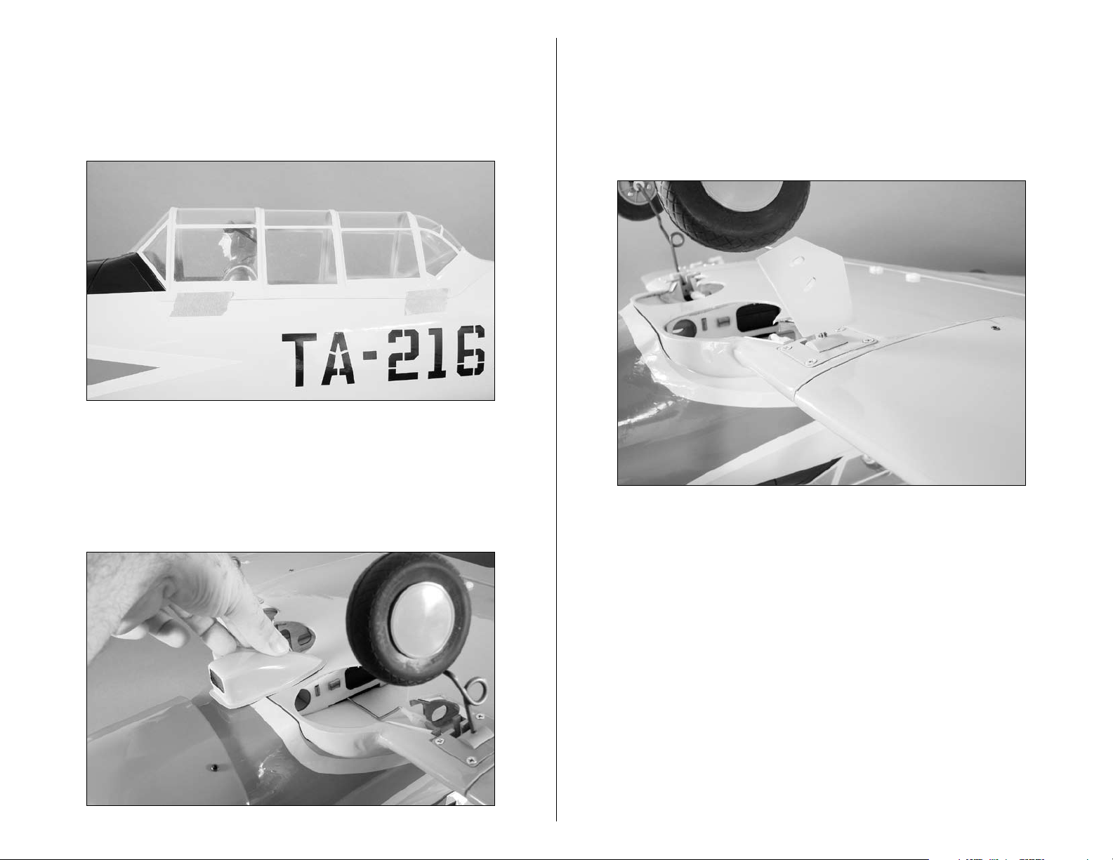
2. Use RC-56 canopy glue to attach the canopy to
the fuselage. Use low-tack tape to hold the canopy in
position until the glue fully cures. Note that the front of
the canopy has a black strip that aligns with the antiglare panel on the front of the fuselage.
3. Position the radiator scoop on the bottom of the wing
center section. A felt-tipped pen can be used to color in
the scoop to give that open look. Trim the radiator scoop
as necessary for a perfect fit and glue it only to the wing
using medium CA.
4. Attach the landing gear fairings to the wheel struts
using two tie wraps per fairing. Use side cutters to
remove the excess material from the tie wraps. Once the
fairings have been attached with the tie straps, you can
add a small drop of Medium CA to the inside to help
secure it so it will not move in flight.
43E-flite AT-6 Texan ARF Assembly Manual
Page 44
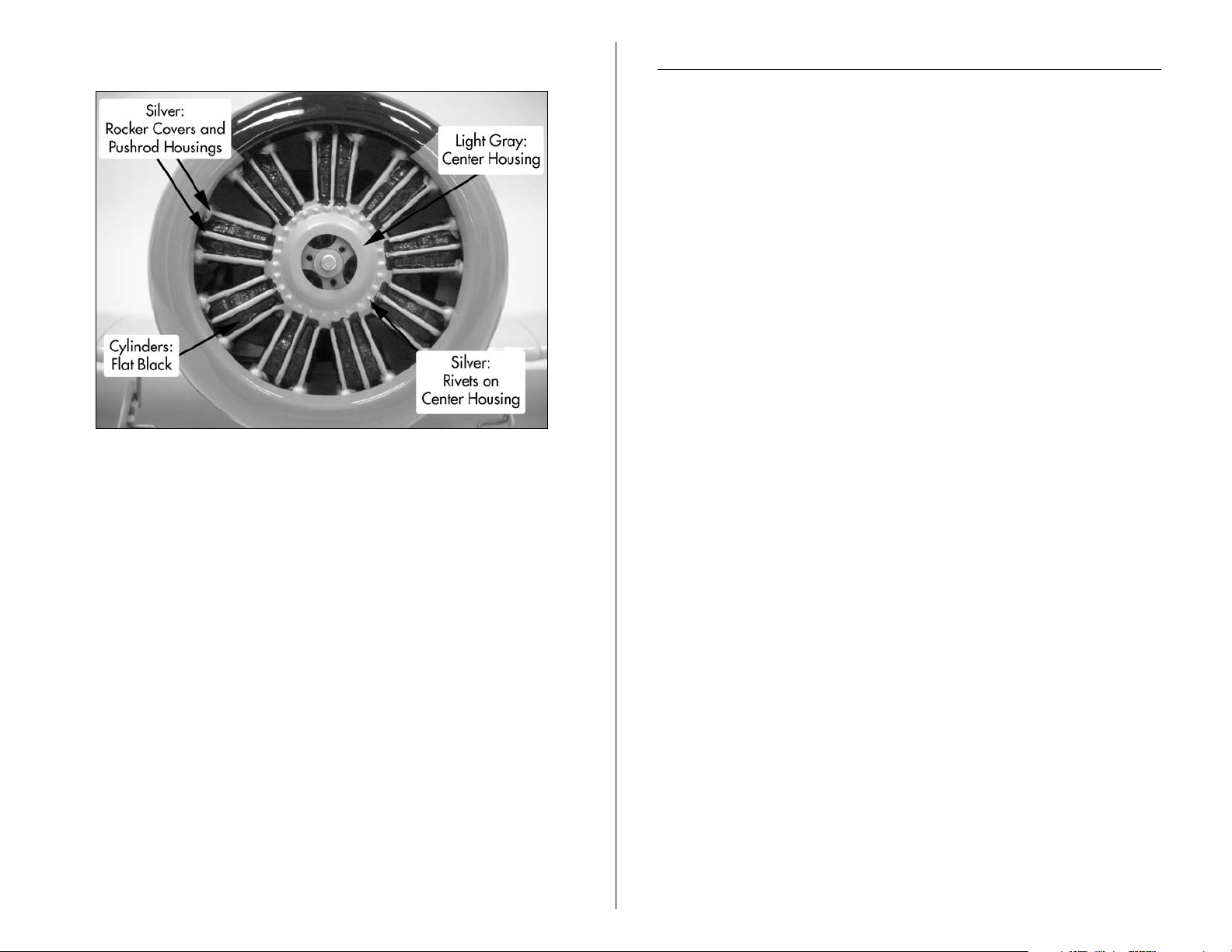
5. Use the following to paint the dummy radial engine.
Optional Scale Cockpit Installation
Required Parts
(Included with kit)
Assembled airframe Pilot figure
Canopy
(Available separately)
Cockpit Kit (EFL4512) Pilot Figure (EFLA150)
Required Tools and Adhesives
Medium CA RC-56 canopy glue
Hobby knife Low-tack tape
Sandpaper Testors Model Master Paints
Note: The cockpit kit comes prepainted from our vendor.
Our first samples were not painted and were painted in
the following colors for those who would like to duplicate
the model as shown on the box.
44 E-flite AT-6 Texan ARF Assembly Manual
Page 45

Floor:
Gun Ship Gray
Instrument hood:
Flat Black
Roll over support structure:
Flat Black for the main support rods and leather for the top cushion.
Seat backs:
Olive Drab for the seat bars and leather for the inside seat area.
1. Remove covering over the cockpit area and sand
the base until smooth.
Note: You may want to tape off the fuselage around the
cockpit opening for the next few steps to help protect the
fuselage during the floor installation.
2. Glue the floor assembly to the fuselage using
medium CA.
45E-flite AT-6 Texan ARF Assembly Manual
Page 46

3. Glue the aft structure in place using Medium CA. You
will want to make sure the canopy will fit on over the aft
structure once in place and not cause any height issues.
4. Glue the two seat backs in place using Medium CA.
The seat backs should rest on the floor.
5. Glue the aft instrument hood in place using Medium
CA. You will want to place the aft instrument decal
from your kit on the panel at this time. Place the front
instrument panel decal in place at this time.
46 E-flite AT-6 Texan ARF Assembly Manual
Page 47

6. Glue the two pilots in place using Medium CA. They
should be placed all the way back, almost against the
seat backs.
7. Use RC-56 canopy glue to attach the canopy to
the fuselage. Use low-tack tape to hold the canopy in
position until the glue fully cures. Note that the front of
the canopy has a black strip that aligns with the antiglare panel on the front of the fuselage.
47E-flite AT-6 Texan ARF Assembly Manual
Page 48

Control Throws
1. Turn on the transmitter and receiver of your AT-6. Check
the movement of the rudder using the transmitter. When
the stick is moved right, the rudder should also move
right. Reverse the direction of the servo at the transmitter if
necessary.
2. Check the movement of the elevator with the radio system.
Moving the elevator stick down will make the airplane
elevator move up.
3. Check the movement of the ailerons with the radio system.
Moving the aileron stick right will make the right aileron
move up and the left aileron move down.
4. Use a ruler to adjust the throw of the elevator, ailerons
and rudder. Adjust the position of the pushrod at the control
horn to achieve the following measurements when moving the
sticks to their endpoints.
Note: Measurements are taken at the widest point on
the surface.
Once all the control throws have been set, make sure to slide
the clevis retainers over the clevises to prevent them from
opening accidentally.
Ailerons
High Rate: 5/8-inch (16mm) (Up/Down)
Low Rate: 3/8-inch (10mm) (Up/Down)
1. Before each flying session, be sure to range check your
radio. This is accomplished by turning on your transmitter
Range Test Your Radio
with the antenna collapsed. Turn on the receiver in your
Elevator
High Rate: 1-inch (25mm) (Up/Down)
Low Rate: 1/2-inch (13mm) (Up/Down)
airplane. With your airplane on the ground and the
engine running, you should be able to walk 30 paces
(approximately 100 feet) away from your airplane and still
have complete control of all functions.
Rudder
3
/
High Rate: 1
-inch (44mm) (Right/Left)
4
Low Rate: 1-inch (25mm) (Right/Left)
These are general guidelines measured from our own flight tests.
You can experiment with higher rates to match your preferred
style of flying.
48 E-flite AT-6 Texan ARF Assembly Manual
If not, don’t attempt to fly! Have your radio equipment
checked out by the manufacturer.
2. Double-check that all controls (aileron, elevator, rudder
and throttle) move in the correct direction.
3. Be sure that your transmitter batteries are fully charged,
per the instructions included with your radio.
Page 49

Center of Gravity
Preflight
An important part of preparing the aircraft for flight is properly
balancing the model.
Caution: Do not inadvertently skip this step!
The recommended Center of Gravity (CG) location for the AT-6
Texan ARF is 4
1
/
– 4
8
1
/
-inch (105–108mm) back from the
4
leading edge of the wing wheel fairing. Please balance your
model upside down with the battery installed. Gear placement
of up or down does not matter.
Check Your Radio
Before going to the field, be sure that your batteries are fully
charged per the instructions included with your radio. Charge
both the transmitter and receiver pack for your airplane. Use
the recommended charger supplied with your particular radio
system, following the instructions provided with the radio. In
most cases, the radio should be charged the night before going
out flying.
Before each flying session, be sure to range check your radio.
See your radio manual for the recommended range and
instructions for your radio system. Each radio manufacturer
specifies different procedures for their radio systems. Next, start
the motor. With the model securely anchored, check the range
again. The range test should not be significantly affected. If it is,
don’t attempt to fly! Have your radio equipment checked out by
the manufacturer.
Note: Keep loose items that can get entangled in
the propeller away from the prop. These include
loose clothing, or other objects such as pencils and
screwdrivers. Especially keep your hands away from the
propeller.
After the first flights, the CG position can be adjusted for your
personal preference.
You may need to add some weight to the nose of your model to
achieve the desired CG. We had to add 2 ounces to the inside
of the cowling on our prototypes. Use commercially available
stick-on weights for this.
Double-check that all controls (aileron, elevator, rudder and
throttle) move in the correct direction.
Check the radio installation and make sure all the control
surfaces are moving correctly (i.e. the correct direction and with
the recommended throws). Test run the motor and make sure
it transitions smoothly from off to full throttle and back. Also
ensure the engine is installed according to the manufacturer’s
instructions, and it will operate consistently.
Check all the control horns, servo horns, and clevises to make
sure they are secure and in good condition. Replace any items
that would be considered questionable. Failure of any of these
components in flight would mean the loss of your aircraft.
49E-flite AT-6 Texan ARF Assembly Manual
Page 50

Flying Your AT-6 Texan ARF
Ensure you have set the model up correctly and have the CG
where it is stated in the instructions. Taxi into the wind and set
the throttle trim to where the motor idles with the prop spinning.
You will need about 200 feet to take off so ensure you have
plenty of room. We like to fly at the local club field instead of
at a park with the AT-6. It is a substantially larger model than
a park flyer and has much more mass. Do not use flaps for
your first takeoff. Power up slowly but smoothly while steering
the model with the rudder and begin your takeoff roll. You will
find the AT-6 accelerates out quickly and the tail will come up
when it is ready. After about 100 feet and while at full power
apply up elevator in a smooth motion until the model lifts from
the ground. Once airborne and climbing out, retract the landing
gear if you installed the optional retracts.
Once in the air you will find the AT-6 is a true warbird in its
element. Straight line flight is easy as well as high banked turns.
This plane grooves like no other 25-size electric on the market
today. Aileron rolls are smooth and precise. Loops are strong
and large. The AT-6 will pick up speed very quickly and can fly
at a brisk pace if you so choose. It is very leisurely in the air
at around 5/8 throttle. Once you are up and have the model
trimmed out, climb to a safe altitude and put the flaps down. Set
them for both the mid and full rate and note any trim changes.
Have your helper make note of any significant trim changes to
the elevator and then set up to land.
To set up to land, put the gear down on the downwind leg and
select full flaps. You will find you will need to carry a small
amount of power when the flaps are deployed. I like to come
around from base leg to final with the nose pointing down at
the runway, flaps full down, and landing gear out. Adjust power
as needed as you fly towards your touchdown point. Once
you are about 2 feet above the ground and beginning to feel
ground effect, you can reduce power and maintain a flat glide
slope until touchdown on the main wheels occurs. The model
enjoys tail high landings with full flaps all day long. You will
be looking like a pro in no time. If you elect to land without the
flaps deployed, I recommend a flared three-point landing as
your best approach.
We hope you enjoy many happy flights with your new E-flite
AT-6 Texan.
50 E-flite AT-6 Texan ARF Assembly Manual
Page 51

2007 Official AMA National
Model Aircraft Safety Code
GENERAL
1) I will not fly my model aircraft in sanctioned events, air shows
or model flying demonstrations until it has been proven to be
airworthy by having been previously, successfully flight tested.
2) I will not fly my model higher than approximately 400 feet within 3
miles of an airport without notifying the airport operator. I will give
right-of-way and avoid flying in the proximity of full-scale aircraft.
Where necessary, an observer shall be utilized to supervise flying
to avoid having models fly in the proximity of full-scale aircraft.
3) Where established, I will abide by the safety rules for the flying
site I use, and I will not willfully or deliberately fly my models in a
careless, reckless and/or dangerous manner.
4) The maximum takeoff weight of a model is 55 pounds, except
models flown under Experimental Aircraft rules.
5) I will not fly my model unless it is identified with my name and
address or AMA number on or in the model. (This does not apply
to models while being flown indoors.)
6) I will not operate models with metal-bladed propellers or with
gaseous boosts, in which gases other than air enter their internal
combustion engine(s); nor will I operate models with extremely
hazardous fuels such as those containing tetranitromethane or
hydrazine.
RADIO CONTROL
1) I will have completed a successful radio equipment ground range
check before the first flight of a new or repaired model.
2) I will not fly my model aircraft in the presence of spectators until I
become a qualified flier, unless assisted by an experienced helper.
3) At all flying sites a straight or curved line(s) must be established
in front of which all flying takes place with the other side for
spectators. Only personnel involved with flying the aircraft are
allowed at or in front of the flight line. Intentional flying behind the
flight line is prohibited.
4) I will operate my model using only radio control frequencies
currently allowed by the Federal Communications Commission.
(Only properly licensed Amateurs are authorized to operate
equipment on Amateur Band frequencies.)
5) Flying sites separated by three miles or more are considered safe
from site-to-site interference, even when both sites use the same
frequencies. Any circumstances under three miles separation
require a frequency management arrangement, which may be
either an allocation of specific frequencies for each site or testing
to determine that freedom from interference exists. Allocation plans
or interference test reports shall be signed by the parties involved
and provided to AMA Headquarters.
Documents of agreement and reports may exist between (1) two
or more AMA Chartered Clubs, (2) AMA clubs and individual
AMA members not associated with AMA Clubs, or (3) two or
more individual AMA members.
6) For Combat, distance between combat engagement line
and spectator line will be 500 feet per cubic inch of engine
displacement. (Example: .40 engine = 200 feet.); electric motors
will be based on equivalent combustion engine size. Additional
safety requirements will be per the RC Combat section of the
current Competition Regulations.
7) At air shows or model flying demonstrations, a single straight line
must be established, one side of which is for flying, with the other
side for spectators.
8) With the exception of events flown under AMA Competition rules,
after launch, except for pilots or helpers being used, no powered
model may be flown closer than 25 feet to any person.
9) Under no circumstances may a pilot or other person touch a
powered model in flight.
51E-flite AT-6 Texan ARF Assembly Manual
Page 52

11067
© 2007 Horizon Hobby, Inc.
4105 Fieldstone Road
Champaign, Illinois 61822
(877) 504-0233
horizonhobby.com
E-fliteRC.com
 Loading...