

Page 1

Apprentice RTF
Assembly Manual
Specifications
Wingspan: 58 in (1475mm)
Length: 37 in (940mm)
Wing Area: 525 sq in (33.7 sq dm)
Weight w/o Battery: 32–35 oz (910–1000 g)
Weight w/Battery: 40–45 oz (1135–1275 g)
Page 2

Table of Contents
Introduction
Introduction ......................................................................... 2
Using the Manual ................................................................ 2
Contents of Kit/Parts Layout ................................................. 3
Required Tools and Adhesives .............................................. 3
Optional Accessories ........................................................... 3
Note on Lithium Polymer Batteries ........................................ 3
Important Warranty Information ........................................... 3
Charging the Flight Battery .................................................. 4
Tail Installation ....................................................................6
Landing Gear Installation ..................................................... 9
Checking the Receiver ........................................................ 10
Wing Installation ............................................................... 11
Battery Installation ............................................................. 14
Installing the Transmitter Batteries .......................................16
Removing the Propeller ...................................................... 17
Control Functions............................................................... 19
Centering the Control Surfaces and
Checking Control Direction ...................................... 20
Center of Gravity .............................................................. 29
Range Test Your Radio ....................................................... 30
Flying Your Apprentice ...................................................... 31
Setting the Control Throws ................................................. 32
Installing the Propeller........................................................ 35
Warning ........................................................................... 37
Instructions for Disposal of WEEE by
Users in the European Union ................................... 37
Optional Items for Your Apprentice ..................................... 38
LiPo Battery Pack Information ............................................. 39
Warranty Information ........................................................ 41
Safety, Precautions, and Warnings ..................................... 43
2008 Official AMA National Model Aircraft Safety Code ... 44
Building and Flying Notes .................................................. 45
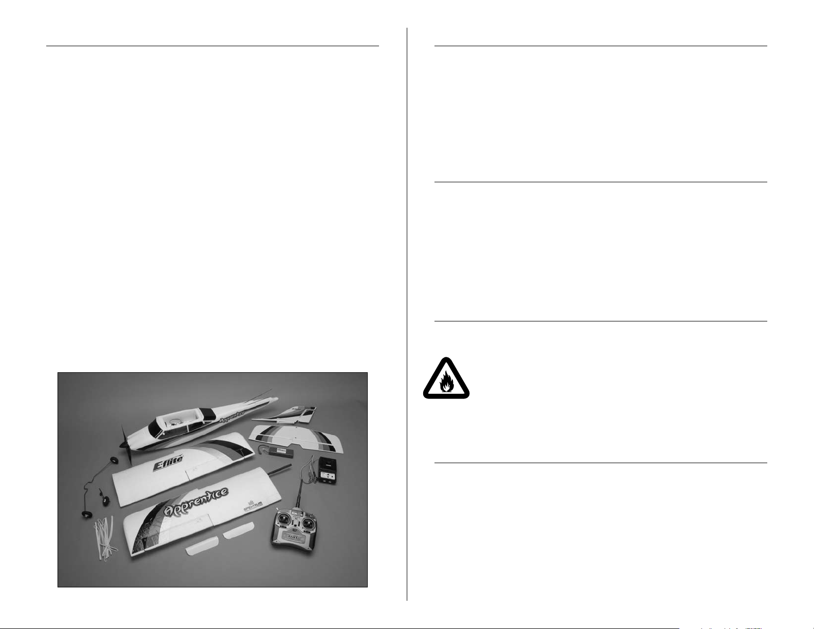
The E-flite® Apprentice RTF is a 15-size high wing trainer,
constructed of lightweight, durable Z-Foam
ready-to-fly trainer comes with everything needed to go from
purchase directly to the field. This includes the full-range
Spektrum
technology and AR500 full-range receiver which will provide you
with years of flying. No building is required for this model. Simply
charge and install the battery, mount the wing and tail, install the
landing gear and go flying.
The Apprentice is powered with a 15-size brushless motor that
provides excellent power and performance. This trainer has a flatbottom wing that produces gentle flight characteristics. This trainer
enables the pilot to learn how to fly through buddy-box training
and progression to aerobatics, as the skills of the pilot allow. The
Apprentice is capable of flying mild aerobatics including inverted
flight, performing loops, and rolls. This model is equipped with
tricycle landing gear allowing better ground handling over taildragger aircraft. This landing gear setup is durable and will also
allow takeoffs and landings on maintained grass runways. This is
a high-quality trainer with an excellent setup, taking the pilot from
beginner to basic aerobatics all from this one-box purchase. Go
from
™
technology DX5e radio with 2.4GHz interference-free
buy to fly with the Apprentice.
™
. The Apprentice
Using the Manual
This manual is divided into sections to help make assembly
easier to understand, and to provide breaks between each
major section. In addition, check boxes have been placed next
to each step to keep track of its completion. Steps with a single
circle () are performed once, while steps with two circles (
) indicate that the step will require repeating, such as for a
right or left wing panel, two servos, etc.
Remember to take your time and follow the directions.
The Spektrum trademark is used with
permission of Bachmann Industries, Inc.
2 E-flite Apprentice Assembly Manual
Page 3
Contents of Kit/Parts Layout
Required Tools and Adhesives
EFL2726 Wing Set
EFL2727 Fuselage
EFL2728 Tail Set
EFL2729 Cowl
EFL2730 Pushrod Set
EFL2731 Nose Gear
EFL2732 Main Landing Gear
EFL2733 Spinner
EFL2734 Motor Mount
EFL2735 5mm Prop Adapter
EFLA1030 30 Amp Pro Switch-mode
BEC Brushless ESC
EFLB1040 3200mAh 3S 11.1v 15C Li-Po Battery
EFLC3010 3 Amp 12V balancing Li-Po charger
EFLM7215 BL15 outrunner, 840 kV motor
EFLP11080E 11 x 8 Electric Propeller
EFLR7130 12g sub micro servo (used on ailerons)
EFLR7140 13g sub micro servo (used on elevator)
EFLR7150 37g standard servo (used on rudder)
SPM5500 DX5e Radio system
SPMAR500 AR500 DSM2 Full-Range Receiver
Tools & Equipment
EFLA250 Parkflyer Tool Assortment, 5-piece
Or Purchase Separately
Phillips screwdriver: #1
Adjustable wrench
Ruler
Optional Accessories
EFLA110 Power Meter
EFLC3005 Celectra
EFLC505 Intelligent 1- to 5-Cell Balancing Charger
EFLB32003S 3200mAh 3S 11.1V 20C LiPo Battery
EFLP11080E 11x8 Electric Prop
SPM6805 Trainer Cord
DYN4055 12-Volt, 10-Amp Power Supply
™
1- to 3-Cell LiPo Charger
Note on Lithium Polymer Batteries
Lithium Polymer batteries are significantly more
volatile than alkaline or Ni-Cd/Ni-MH batteries used
in RC applications. All manufacturer’s instructions
and warnings must be followed closely. Mishandling
of LiPo batteries can result in fire. Always follow the
manufacturer’s instructions when disposing of Lithium
Polymer batteries.
Important Warranty Information
Please read our Warranty and Liability Limitations section
on Page – before building this product. If you as the
Purchaser or user are not prepared to accept the liability
associated with the use of this Product, you are advised to
return this Product immediately in new and unused condition
to the place of purchase.
3E-flite Apprentice Assembly Manual
Page 4
Charging the Flight Battery
Your Apprentice can be ready to fly in as little time as it takes
to charge the flight battery. Since this takes approximately 60
minutes, let's get the battery charging right away so it's on
charge while you're assembling your new Apprentice. That way
you can start flying as soon as possible.
Required Parts
Charger
3200 3S 11.1V LiPo battery
Power supply or 12-volt battery (not included)
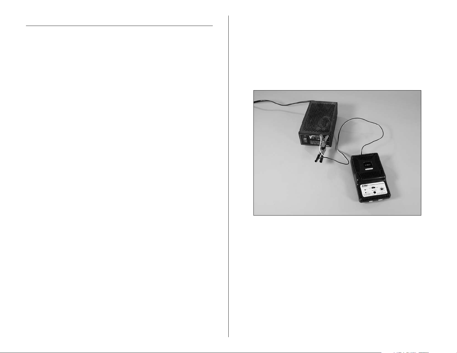
Note: The battery charger can be connected to a power
supply or 12-volt battery. For the pictures in this manual
we will show the use of a power supply.
1. Connect the charger to a 12-volt battery or 12-volt
power supply. Connect the red lead to the positive (+)
terminal of the power supply or battery. Connect the
black lead to the negative (-) terminal of the power
supply or 12-volt battery. Once your charger has been
correctly powered up, there will be an approximate
3-second delay and then you will hear an audible “beep”
and the green (ready) LED will flash.
4 E-flite Apprentice Assembly Manual
Page 5
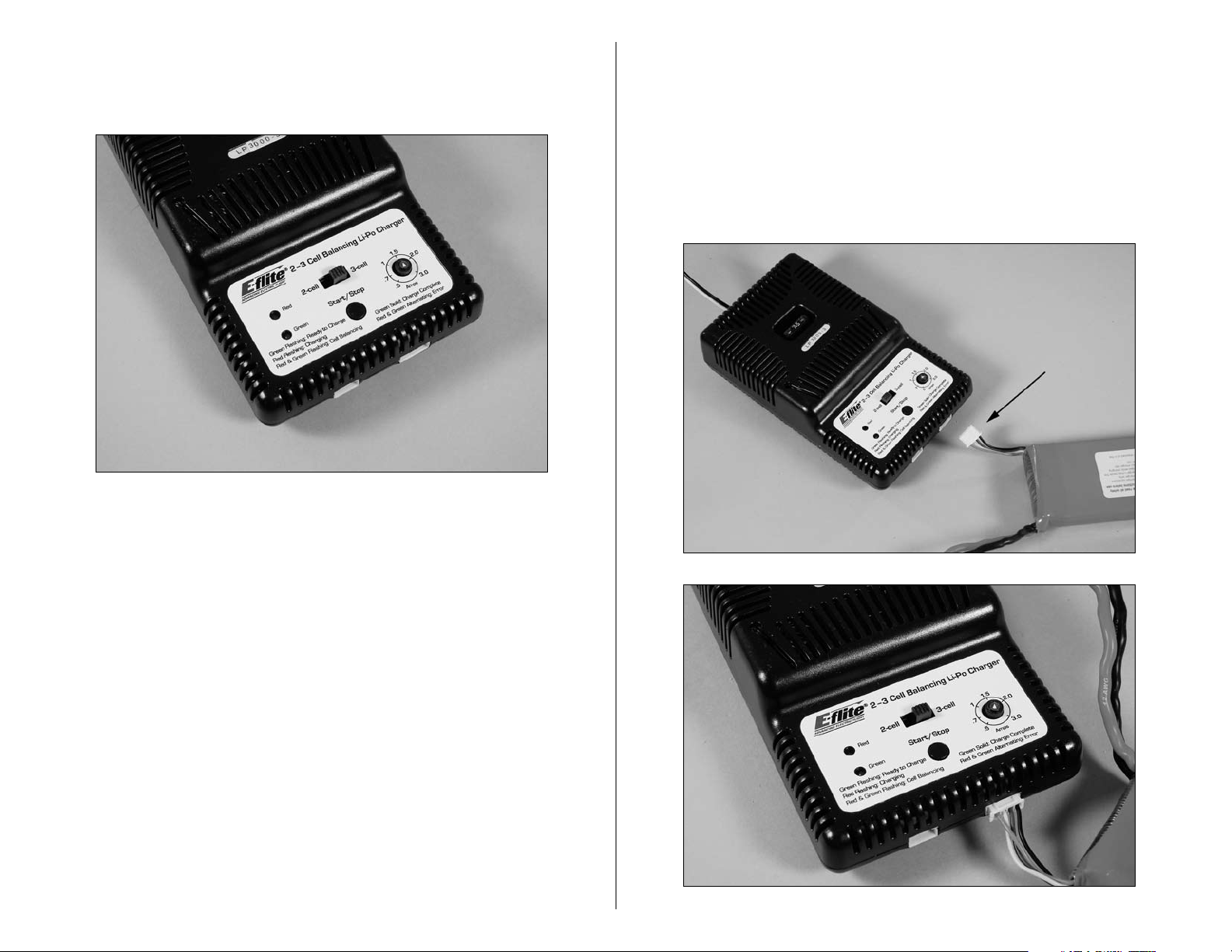
2. Select the proper number of cells that you will be
charging. Your Apprentice includes a 3-cell flight pack,
so set the charger to 3 cells.
4. Locate the balance charge lead on the battery pack.
The charge lead of a 3-cell LiPo battery will plug into
the larger 4-pin port on the bottom right of the charger.
A 2-cell pack will need to plug into the 3-pin port on
bottom left of the charger. Once the battery is properly
plugged into the correct port, it will beep 3 times if it is a
3-cell, and twice if it is a 2-cell pack. Once this is done,
you are ready to proceed to charge the battery pack.
3. Set the charge rate for your battery to 3 amps.
Warning: Selecting a charge rate higher than 1x battery
capacity may cause a fire. If the battery capacity is
3000mAh, then set your charger no higher than 3 amps.
5E-flite Apprentice Assembly Manual
Page 6
5. Push the start button to begin the charging process.
Once this is done, the charger will make an audible beep
that matches the cell count, and then the red (charge)
LED will begin to flash. Do not adjust the current once the
charger has begun to charge.
Note: At times, the green LED may also flash during
the charging process, indicating that the charger is
balancing one or more of the cells at the same time it
is charging the battery pack. When this is occurring,
the red and green LEDs will both be flashing. It will not
always be necessary for the cells to be balanced.
6. When the battery pack is fully charged, you will hear
an audible beep for about 3 seconds, and the green LED
will be solid. Always unplug the battery from the charger
immediately upon completion. Failure to do so could
cause a fire.
Note: Lithium Polymer batteries, commonly known as
LiPos, are not quite like other batteries.
Tail Installation
Required Parts
Fuselage Assembly Stabilizer/Elevator
Fin/Rudder
2.5mm x 12mm sheet metal screw (2)
Required Tools
Phillips screwdriver: #1
1. Position the stabilizer on the fuselage. Align the holes
in the stabilizer with the holes in the rear of the fuselage.
The decals on the stabilizer will face toward the top of
the fuselage.
First, they do not develop any sort of memory
characteristics due to partial use or partial charging.
They can be used as little or as much as needed,
then charged back up to capacity without any loss in
performance.
Second, they do have one quirk that should be
explained. If a LiPo battery is discharged to a voltage
less than about 3.0V per cell (9.0 volts total for the
battery in the Apprentice), then it will be permanently
damaged and cannot be restored. The electronic speed
control in the Apprentice is pre-set to a cutoff voltage that
will not allow the battery to drain less than this amount.
6 E-flite Apprentice Assembly Manual
Page 7
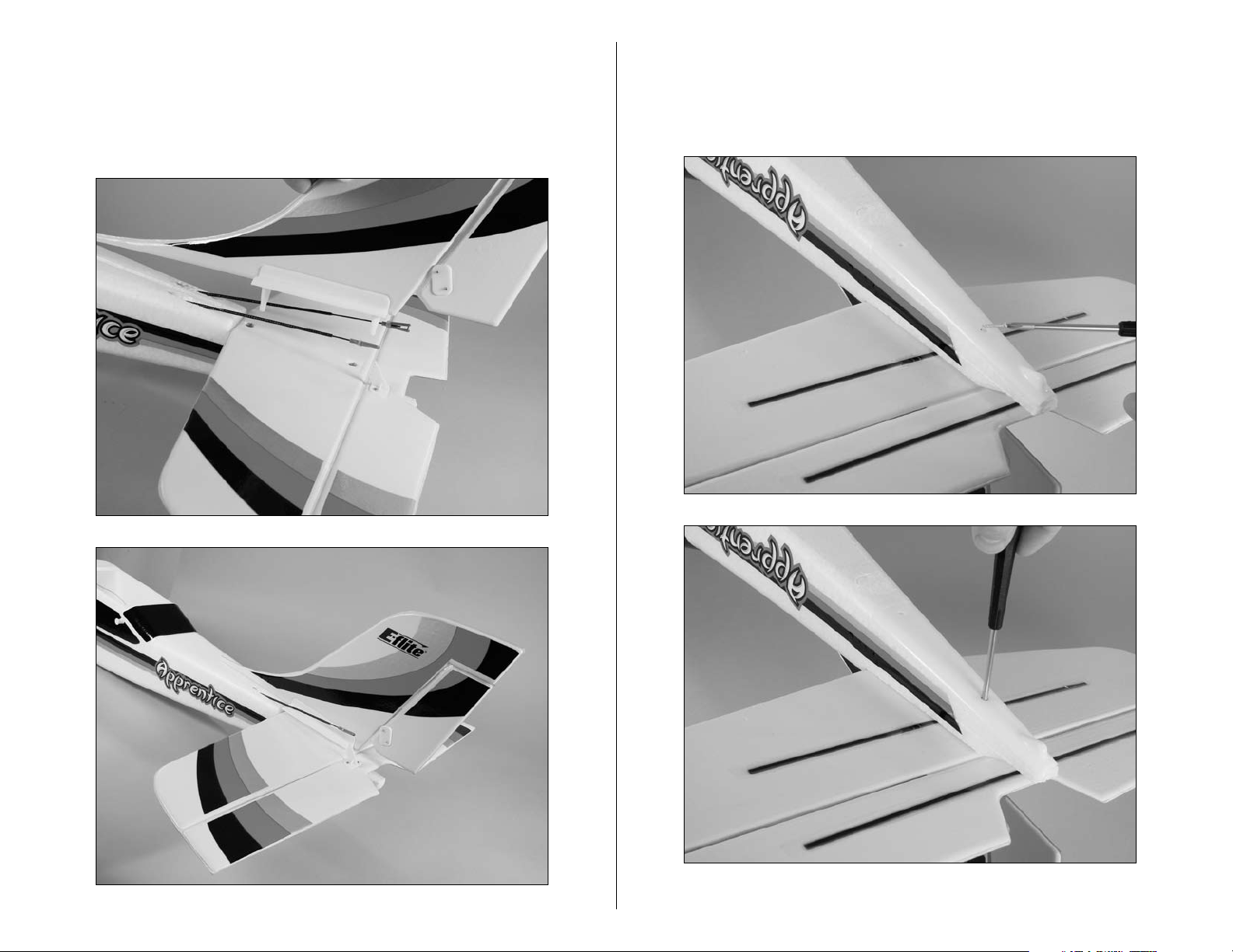
2. Slide the pins on the bottom of the fin through the
holes of the stabilizer and into those in the fuselage.
Make sure to seat the fin completely down on the
horizontal stab. You might need to push the fin down
with some slight pressure to fully seat it.
3. Use a #1 Phillips screwdriver to install the two
2.5mm x 12mm sheet metal screws that secure the
tail assembly to the fuselage. Tighten the screws until they
stop. Do not overtighten as you may crack the plastic.
7E-flite Apprentice Assembly Manual
Page 8

4. Connect the elevator pushrod clevis to the elevator
control horn in the hole that is farthest away from the
elevator. Make sure to slide the silicone retainer onto the
clevis to keep the clevis from popping off of the control
horn.
5. Connect the rudder pushrod clevis to the rudder
control horn in the hole that is farthest away from the
rudder. Make sure to slide the silicone retainer onto the
clevis to keep the clevis from popping off of the control
horn.
Note: For new pilots, we recommend installing the clevis
for both the elevator and rudder pushrods in the outermost hole on the control horn.
8 E-flite Apprentice Assembly Manual
Page 9
Landing Gear Installation
Required Parts
Fuselage Assembly Nose gear w/wheel
Main gear w/wheels
Required Tools
Phillips screwdriver: #1
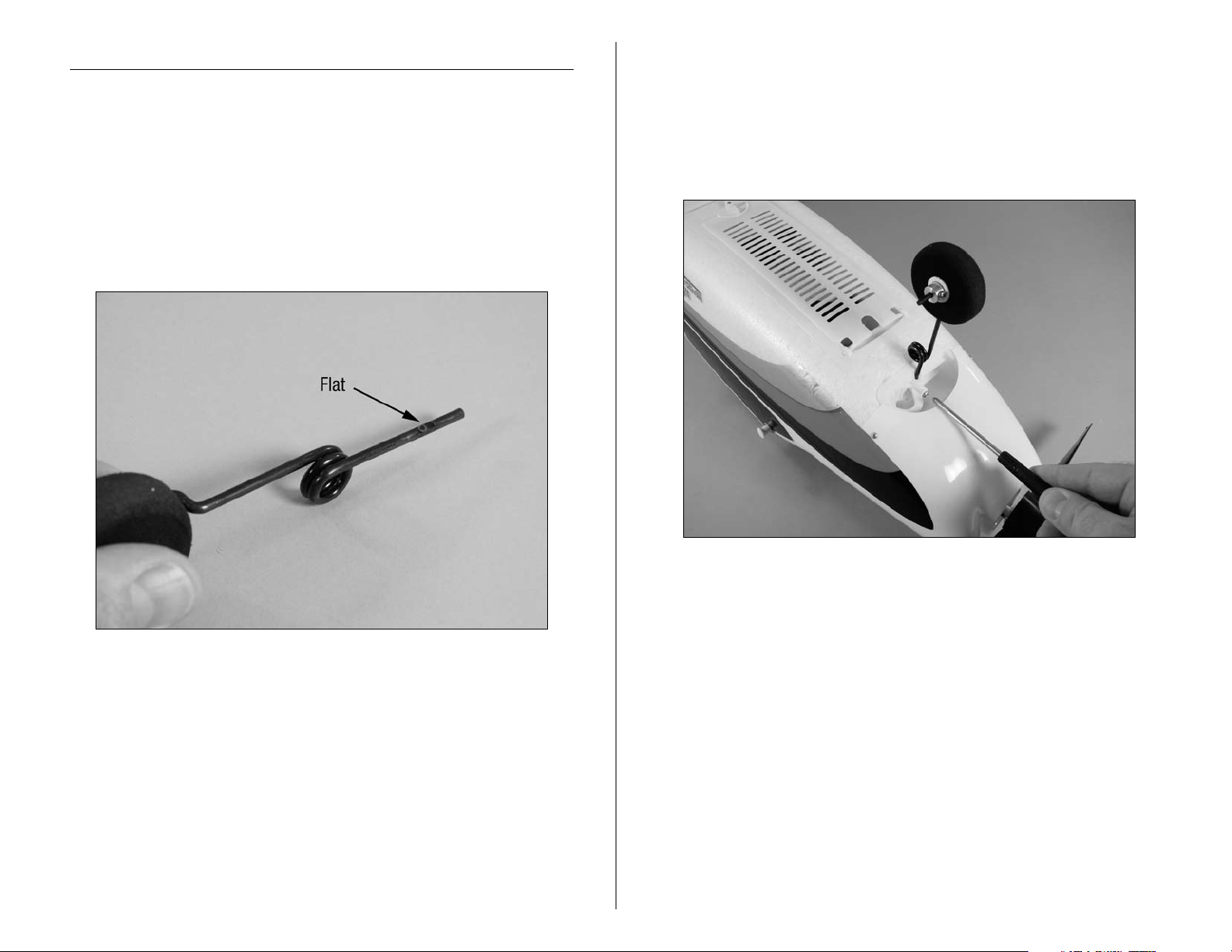
1. Locate the flat area on the nose gear. This area will be
where the screw will be positioned in the following step.
2. You will need to back out the screw in the nose wheel
steering arm before sliding in the nose gear wire. Slide
the nose gear into the nose gear bracket. Use a #1
Phillips screwdriver to tighten the screw that secures the
nose gear. Make sure the screw is tightened against the
flat area as indicated in Step 1.
Note: You may need to push the cowling out of the way
slightly to access the screw. The cowl material is flexible
enough to bend a little during this step without damage.
9E-flite Apprentice Assembly Manual
Page 10
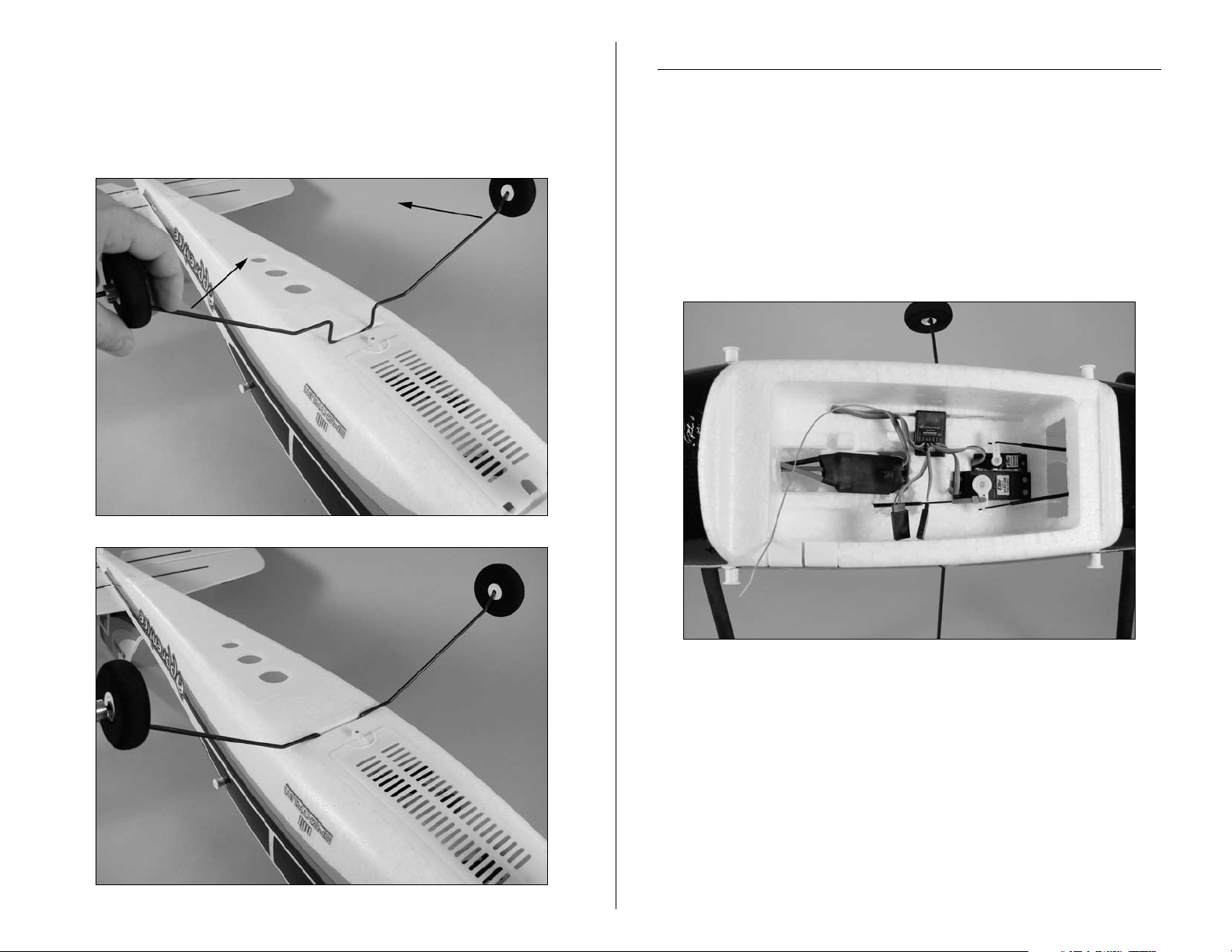
3. Locate the main gear and press it into the slot in the
fuselage that is behind the battery compartment on the
bottom of the fuselage. You may need to flex the landing
gear wire inwards towards itself to get it to fully seat
inside the slot.
Checking the Receiver
Required Parts
Fuselage Assembly
1. Check that the servos and speed control are plugged
into the receiver properly. The speed control is plugged
into the slot marked "THRO", the smaller servo in the
slot marked "ELEV", the larger servo in "RUDD" and the
connector that has the two leads for the ailerons into the
slot marked "AILE."
10 E-flite Apprentice Assembly Manual
Page 11
Wing Installation
Required Parts
Wing panel (right and left) Wing cover, front
Wing cover, rear Rubber band (8)
Fuselage assembly
1. Align the carbon wing tube with the socket in the
opposite wing panel. Slide the two panels tightly together.
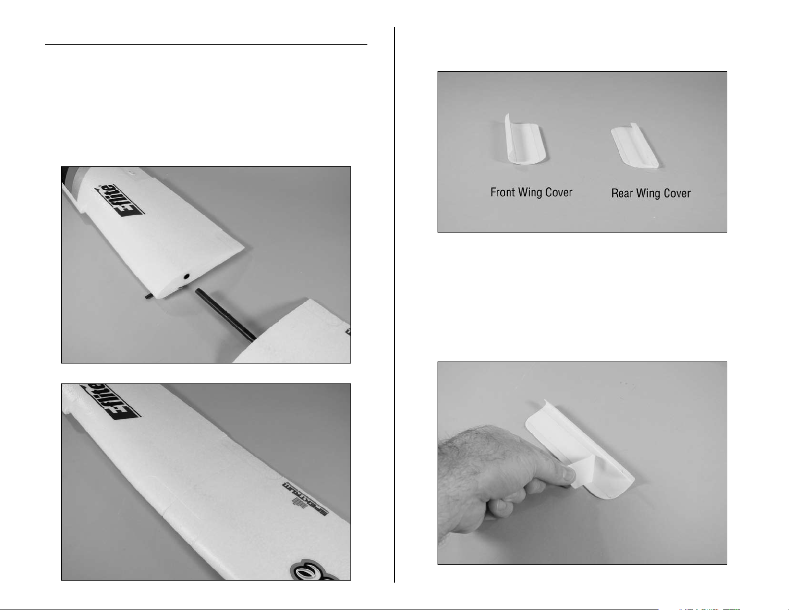
2. Locate the front and rear wing covers. The front cover
has a rounded edge, while the rear has a squared edge.
Hint: You may want to practice the next steps before
removing the backing from the adhesive tape on the
wing covers. The adhesive will stick as soon as it touches
the wing surface.
3. Remove the backing from the adhesive tape on the
front wing cover.
11E-flite Apprentice Assembly Manual
Page 12
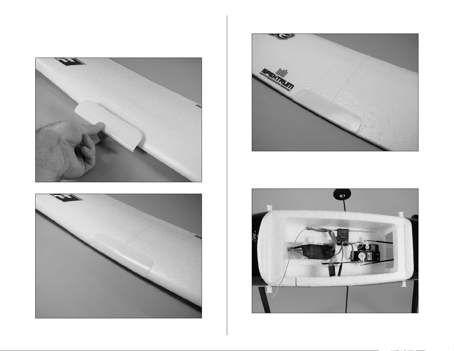
4. Make sure the two wing panels are pressed tightly
together with no gap between them. Position the front
wing cover in the notch at the front of the wing. Press the
cover down to secure its position on the wing.
5. Repeat the previous step to install the rear wing cover.
6. Install the included Y-harness by plugging it into the
Aile port of the receiver.
12 E-flite Apprentice Assembly Manual
Page 13
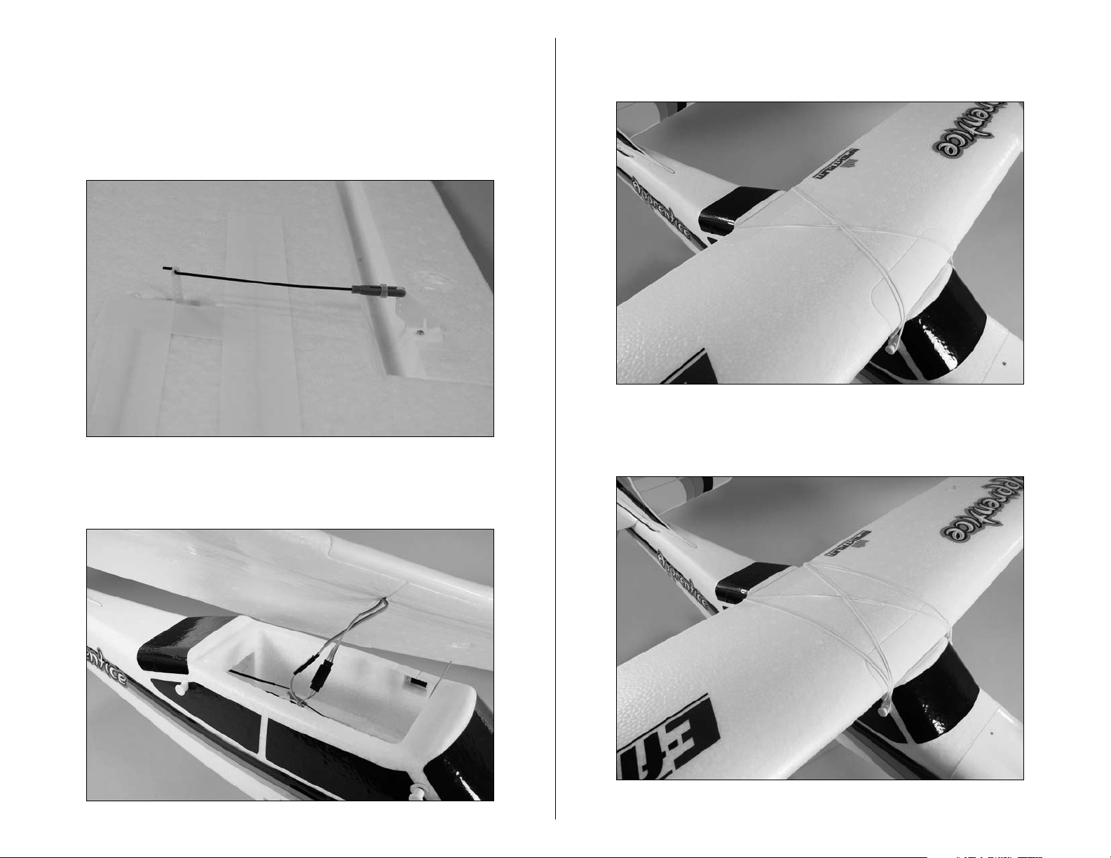
7. Connect the aileron pushrod clevis to the aileron
control horn in the hole that is farthest away from the
aileron. Make sure to slide the silicone retainer onto the
clevis to keep the clevis from popping off of the control
horn. Connect both the right and left aileron linkages at
this time.
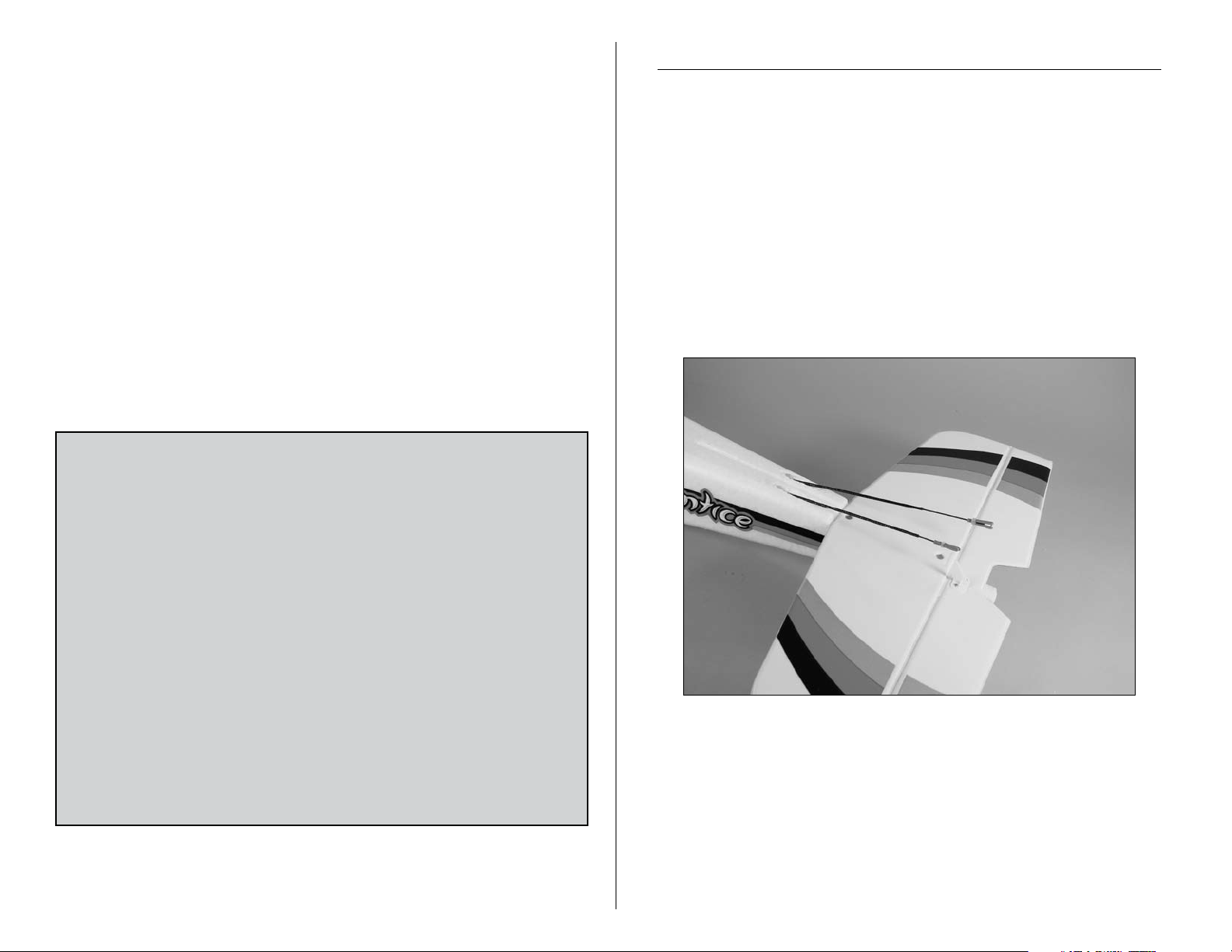
9. Install the first two rubber bands. They should cross as
shown in the image below.
10. The next two rubber bands will go directly from the
front to the rear of the fuselage, over the wing.
8. Connect the wires from the aileron servos to the
Y-harness coming from the receiver.
13E-flite Apprentice Assembly Manual
Page 14
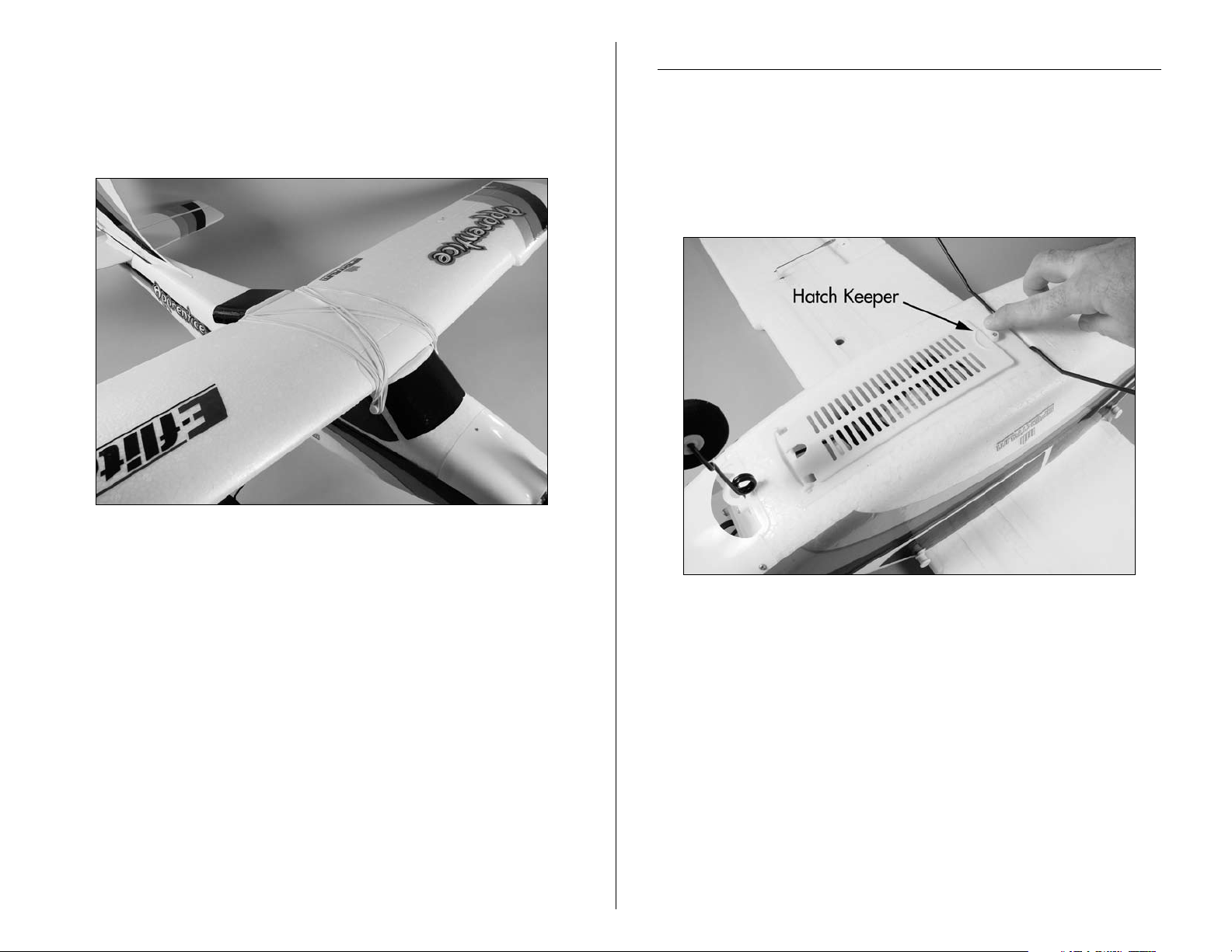
11. Install the last four rubber bands using the Steps 9
and 10 as a guide. You will install two across (as in step
9) and then two in line (as in step 10), and then two
across (as in step 9) and then two in line (as in step 10),
and so on until there are no more rubber bands.
Battery Installation
Required Parts
Assembled airframe
3200 3S 11.1 V LiPo battery (charged)
1. Turn the battery hatch keeper 90 degrees to release
the hatch.
14 E-flite Apprentice Assembly Manual
Page 15
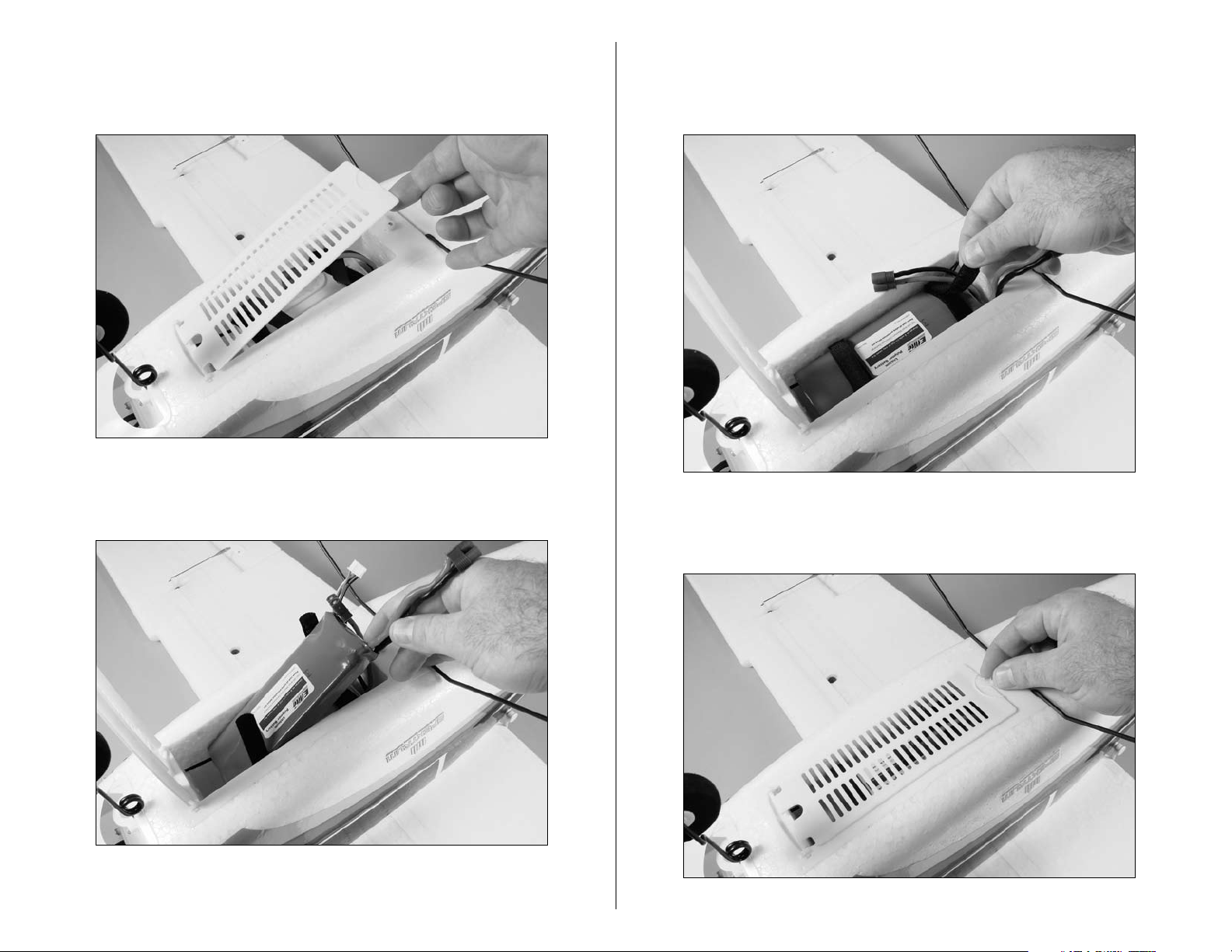
2. Open the hatch from the rear of the fuselage as
shown. The front of the hatch is hinged so it will not
detach from the fuselage and get lost.
3. Slide the battery into the battery compartment. The
connector will face the back of the airplane.
4. Ensure the battery is slid all the way into the front of
the battery compartment. Use the hook and loop straps to
secure the battery in the fuselage.
5. Close the hatch from the rear of the fuselage. Turn the
battery hatch keeper 90 degrees to secure the hatch.
15E-flite Apprentice Assembly Manual
Page 16

Installing the Transmitter Batteries
Required Parts
Transmitter AA battery (4)
1. Check to make sure the transmitter power switch is in
the "OFF" position.
3. Remove the battery cover and set it aside so it does
not get lost.
4. Install the four AA batteries. Note the polarity of the
batteries during their installation.
2. Slide the cover from the battery compartment.
16 E-flite Apprentice Assembly Manual
Page 17

5. Slide the battery cover back into position on the back
of the transmitter.
Note: The installation of the batteries is also covered
in your radio manual. Please read through the radio
manual to familiarize yourself with the operation of your
radio system.
Removing the Propeller
Required Parts
Fuselage assembly
Required Tools
Adjustable wrench
Important: Before performing any maintainance to the
motor, make sure the battery has been unplugged and
removed from your model to prevent injury. Also remove
the propeller when checking the radio system to prevent
any personal injury if the motor were to start.
1. Remove the spinner cone from the spinner. It should
snap away from the backplate with a little force.
17E-flite Apprentice Assembly Manual
Page 18

2. Use an adjustable wrench to remove the nut from the
propeller adapter. Set the nut aside so it does not get lost.
3. Remove the washer and set it aside with the nut and
spinner cone.
4. Remove the spinner backplate and set it with the nut,
spinner cone and washer.
18 E-flite Apprentice Assembly Manual
Page 19

5. Slide the propeller from the propeller adapter. The
Elevator/Rudder Stick
Throttle/Aileron Stick
Reversing Switches
Mix Switch (not used for Apprentice)
Elevator Trim
Rudder Trim
Aileron Trim
Throttle Trim
HI/LO
Rate Switch
installation of the propeller is the reverse of the previous
steps. Make sure the nut is tightened properly so the
propeller does not depart from your model during flight.
Control Functions
Required Parts
Transmitter
The following images to identify the controls for both the
Mode 1 and Mode 2 versions of your Apprentice.
Note: Once the radio system has been checked, the
propeller can then be installed. Refer to the section
"Installing the Propeller" later in this manual for details.
Mode 1 Transmitter
19E-flite Apprentice Assembly Manual
Page 20

Throttle/Rudder Stick
Elevator/Aileron Stick
Reversing Switches
Mix Switch (not used for Apprentice)
Throttle Trim
Rudder Trim
Aileron Trim
Elevator Trim
HI/LO
Rate Switch
Mode 2 Transmitter
Switch
Centering the Control Surfaces and
Checking Control Direction
Required Parts
Assembled airframe Flight battery
Transmitter
Note: This section is designed to help you become
acquainted with the operation of the radio in correlation
to the model. If a flight control moves in the incorrect
direction we will instruct you how to change it in the
next section. As always, read through the radio manual
which explains the features of your radio system.
1. Turn the radio on using the power switch on the front
of the transmitter and check that the throttle stick is at its
lowest position. The throttle stick needs to be in the idle/
off position, otherwise the speed control will not arm
in the next step. The DX5e transmitter features digital
trims, so they should be centered when the transmitter is
powered on.
20 E-flite Apprentice Assembly Manual
Page 21

2. Plug the EC3 connector on the flight battery into the
Centered
Up—Thread clevis out
Down—Thread clevis in
speed control. You will hear a series of beeps or tones
when you plug the battery in. During this process it is
normal for the prop to pulse slightly as the ESC powers
up. Please ensure you are not in line with the prop or in
front of it during power up.
Note: The following steps will ensure your flight controls
are centered for the first flight.
Checking the Elevator (Mode 2)
3. Center the elevator stick. This is the right stick on the
transmitter. The elevator should not be deflected up or
down, but should be flat with the horizontal stabilizer
when viewed from the side. If the elevator is deflected
up or down you will need to push the silicone keeper
back off the clevis, onto the pushrod. This will enable
you to open the clevis up and remove it from the control
horn. Once removed, screw the clevis in or out to get the
elevator to line up with the stab.
Important: Always use extreme caution around the
propeller when the motor battery is plugged in. A
spinning propeller can cause serious damage or injury.
It is always best to stay behind the propeller and keep
it away from loose objects when the battery and speed
control are connected.
When the battery is connected, you will hear one low
long tone to indicate startup, then the respective number
of medium-length mid tones to indicate the cell count or
a musical tone, followed by three rising tones to indicate
the controller is armed. For more information on your
speed control, refer to the included instructions.
21E-flite Apprentice Assembly Manual
Page 22

4. Check the movement of the elevator with the radio
system. Pulling the elevator/aileron stick (right stick on
the Mode 2 transmitter) back will make the airplane
elevator move up.
5. Check the movement of the elevator with the radio
system. Pushing the elevator/aileron stick forward will
make the airplane elevator move down on the Mode 2
transmitter.
22 E-flite Apprentice Assembly Manual
Page 23

Checking the Elevator (Mode 1)
3. Center the elevator stick. This is the left stick on the
transmitter. The elevator should not be deflected up or
down, but should be flat with the horizontal stabilizer
when viewed from the side. If the elevator is deflected
up or down you will need to push the silicone keeper
back off the clevis, onto the pushrod. This will enable
you to open the clevis up and remove it from the control
horn. Once removed, screw the clevis in or out to get the
elevator to line up with the stab.
4. Check the movement of the elevator with the radio
system. Pulling the elevator/rudder stick (left stick on the
Mode 1 transmitter) back will make the airplane elevator
move up.
23E-flite Apprentice Assembly Manual
Page 24

5. Check the movement of the elevator with the radio
Centered
Right—Thread clevis out
Left—Thread clevis in
system. Pushing the elevator/rudder stick forward will
make the airplane elevator move down on the Mode 1
transmitter.
Checking the Rudder (Mode 1 and 2)
6. Mode 1 (Rudder/Elevator on left stick): Center the
rudder stick. Thread the clevis in or out on the rudder
pushrod until the rudder is aligned with the fin as shown.
Mode 2 (Rudder/Throttle on left stick): Confirm the
rudder stick is in the down/throttle off position. Thread
the clevis in or out on the rudder pushrod until the rudder
is aligned with the fin as shown.
24 E-flite Apprentice Assembly Manual
Page 25

7. Check the movement of the rudder using the
transmitter. When the rudder/throttle stick (left side
of the transmitter) is moved right, the rudder should
also move right.
8. Check the movement of the rudder using the
transmitter. When the left stick is moved left, the
rudder should also move left.
Important: When operating a Mode 2 transmitter
(rudder/throttle on left stick), be very careful that the
left stick is not moved forward when checking the
rudder. Moving the rudder stick forward will result in the
propeller spinning.
25E-flite Apprentice Assembly Manual
Page 26

Checking the Steering Trim (Mode 1 and 2)
Aircraft turns right—
Thread clevis IN at rudder servo
Aircraft turns left—
Thread clevis OUT at rudder servo
Note: Checking the steering trim must be done after
the aircraft has been flown and the rudder trimmed for
straight flight at the transmitter. The steering trim is a
mechanical adjustment and should never be corrected
using the rudder trim at the transmitter.
9. Once the rudder has been trimmed for straight flight,
you can now adjust the steering trim of your Apprentice.
Taxi the aircraft to determine if it turns left or right when
the rudder stick is centered. Do not change the rudder
trim at the transmitter. If the aircraft turns right, thread
the clevis IN at the rudder servo, which will shorten the
steering linkage. If the aircraft turns left, thread the clevis
OUT at the rudder servo, which will lengthen the steering
linkage. Adjust until the aircraft will taxi in a straight line
without any rudder control inputs.
26 E-flite Apprentice Assembly Manual
Page 27

Checking the Ailerons (Mode 1 and 2)
Centered
Up—Thread clevis in
Down—Thread clevis out
10. Center the aileron stick. Thread the clevis in or out on
the aileron pushrod until the ailerons are aligned with the
wing as shown.
11. Check the movement of the aileron using the
transmitter. When the elevator/aileron stick (Mode 2
transmitter) or throttle/aileron stick (Mode 1 transmitter)
is moved right, the right aileron will move up and the left
aileron will move down.
27E-flite Apprentice Assembly Manual
Page 28

12. Check the movement of the aileron using the
transmitter. When the aileron/elevator stick (Mode
2 transmitter) or the aileron/throttle stick (Mode 1
transmitter) is moved left, the left aileron will move up
and the right aileron will move down.
Reversing Direction of Flight Controls
If you find any control surface moving in the opposite direction of
what it should (example shown below), use the Servo Reversing
feature of the DX5e to fix the problem. Reversing switches for all
of the control functions are located on the front of the transmitter
below the power switch. Locate the appropriate switch, slide it
to the new position, and check to see if the surface in question is
now moving in the right direction.
28 E-flite Apprentice Assembly Manual
Page 29

13. This completes the radio setup section. You may now
power down your airplane and transmitter. To do this
follow these steps.
A. Unplug the aircraft battery
B. Turn transmitter off.
Center of Gravity
An important part of preparing the aircraft for flight is properly
balancing the model.
Caution: Do not inadvertently skip this step!
The recommended Center of Gravity (CG) location for the
1
/
Apprentice is 3
the top wing. Mark the location for the Center of Gravity on the
bottom of the top wing in the center as shown.
When balancing your Apprentice, support the plane upright
at the marks made on the bottom of the wing with your fingers
or a commercially available balancing stand. Move the speed
control and/or receiver as necessary so the model hangs level
or slightly nose down. This is the correct balance point for your
model.
inch (83mm) back from the leading edge of
4-
29E-flite Apprentice Assembly Manual
Page 30

Apprentice Balanced - No Correction Needed
Apprentice Nose Heavy -
Add Weight to Tail or Move Battery Rearward
Apprentice Tail Heavy -
Add Weight to Nose or Move Battery Forward
Range Test Your Radio
HI/LO Rate Switch
Trainer Switch
Before each flying session, and especially with a new model, it
is important to perform a range check. The DX5e incorporates
a range testing system which, when placed in the range check
mode with the trainer switch activated and held, reduces the
output power, allowing a range check.
1. With the model resting on the ground, stand 30 paces
(approximately 90 feet) away from the model.
2. Face the model with the transmitter in your normal
flying position. Pull and hold the trainer switch while
toggling the HI/LO Rate Switch four times. The LEDs will
flash and the alarm will sound, indicating the system is in
range check mode.
After the first flights, the CG position can be adjusted for your
personal preference.
30 E-flite Apprentice Assembly Manual
Page 31

3. You should have total control of the model with the
30 paces (90 feet/28 meters)
trainer switch pulled at 30 paces (90 feet).
4. If control issues exist, call the Horizon Support Team at
1 877 504 0233 or go to horizonhobby.com to find a
local Spektrum distributor in your country for service.
Flying Your Apprentice
It is strongly recommended for your first flights to search out the
assistance of a qualified instructor, who will help you through
your first flights and assist you in the basics of Radio Controlled
flight. You can find this guidance at your local hobby dealer’s
store. Your Apprentice is capable of flying in winds up to 15 mph
but, for flight training, it is recommended to fly in the lightest
wind possible. You will need to ensure your battery is fully
charged and the model is set up accordingly for your first flight.
Do not attempt to fly the model on a partially charged battery.
Your DX5e can be used with a wide variety of transmitters
when using the buddy box feature. The buddy box feature is
a very useful tool when learning to fly. It allows the instructor
pilot to hold the main transmitter (the DX5e that is included in
your Apprentice kit) while you hold another transmitter which is
called the slave transmitter. These two transmitters are connected
together via a buddy cord (SPM6805) which is called out as an
option on page 3 of this manual. Most instructors at your local
flying field will have one of these cords available for your use
the first time out. While you learn to fly, the flight instructor holds
a trainer switch down which gives you (the student) control of
the model. When you encounter any issues in flight or become
disoriented, the flight instructor releases the switch taking over
control of your model in a split second. The end result is that
the model is never in any serious danger of crashing due to this
great feature. The DX5e is compatible with all JR or Spektrum
transmitters when using the buddy box feature.
31E-flite Apprentice Assembly Manual
Page 32

Setting the Control Throws
Switch
Required Parts
Assembled airframe Charged flight battery
Transmitter
Required Tools and Adhesives
Ruler
Your transmitter and model come out of the box set up and ready
to fly. Should you need to replace your fuselage or wing due to
a mishap or such, this section will help you reset your control
throws to the factory settings.
Note: Measurements are taken at the widest point on
the surface.
These are general guidelines measured from our own flight tests.
You can experiment with different rates to match your preferred
style of flying. Adjusting of the control throws on the Apprentice
15e is not as critical as it is on other models. The measurements
given in this section are approximations and a place to get close
to when replacing parts and resetting control throws. The location
of the pushrod or clevis on the servo arm and control horn of
the flight control surface are given as they come set from the
factory. With this information you should be able to attain settings
that will be very close to the originals and deliver the flight
performance you have come to expect from the Apprentice.
1. Turn the radio on using the power switch on the front
of the transmitter and check that the throttle stick is at its
lowest position. The throttle stick needs to be in the idle/
off position, otherwise the speed control will not arm in
the next step. The DX5e featuers digital trims, so they
should be centered when the transmitter is powered on.
32 E-flite Apprentice Assembly Manual
Page 33

2. Plug the motor battery into the speed control.
Important: Always use extreme caution around the
propeller when the motor battery is plugged in. A
spinning propeller can cause serious damage or injury.
It is always best to stay behind the propeller and keep
it away from loose objects when the battery and speed
control are connected.
Elevator Throw
3. Use a ruler to check the control throws on your
elevator. The dimensions are shown below. For your
reference the elevator pushrod is set up in the following
holes: The outside hole on the elevator control horn and
the fourth hole in on the elevator servo arm.
Low Rate: 3/8-inch (9mm) (Up/Down)
High Rate: 3/4-inch (19mm) (Up/Down)
33E-flite Apprentice Assembly Manual
Page 34

Rudder Throw
Aileron Throw
4. Use a ruler to check the control throws on your rudder.
The dimensions are shown below. For your reference
the rudder pushrod is set up in the following holes: The
outside hole on the rudder control horn and the outside
hole on the rudder servo arm.
Low Rate: 1/2-inch (14mm) (Right/Left)
High Rate: 1-inch (25mm) (Up/Down)
5. Use a ruler to check the control throws on the ailerons.
The dimensions are shown below. For your reference the
aileron pushrods are set up in the following holes: The
outside hole on the aileron control horn and the outside
hole on the aileron servo arm.
Low Rate: 3/8-inch (9mm) (Up/Down)
High Rate: 5/8-inch (16mm) (Up/Down)
34 E-flite Apprentice Assembly Manual
Page 35

6. Once all the control throws have been set, make sure
to slide the clevis retainers over the clevises to prevent
them from opening accidentally.
Installing the Propeller
Required Parts
Fuselage assembly Propeller
Propeller nut Propeller washer
Spinner cone Spinner backplate
Required Tools
Adjustable wrench
Important: Before performing any maintainance to the
motor, make sure the battery has been unplugged and
removed from your model to prevent injury.
1. Slide the propeller on the propeller adapter.
7. For your reference the nose wheel steering pushrod is
set up in the following holes: The fixed position hole on
the nose wheel steering arm and the outside hole on the
rudder servo arm.
35E-flite Apprentice Assembly Manual
Page 36

2. Slide the spinner backplate on the propeller adapter.
3. Install the washer on the propeller shaft.
4. Thread the nut on the propeller adapter. Use an
adjustable wrench to tighten the nut. Make sure the nut is
tightened properly so the propeller does not depart from
your model during flight.
36 E-flite Apprentice Assembly Manual
Page 37

5. Snap the spinner cone on the spinner backplate. It
should snap on the backplate using a little force.
Warning
An RC aircraft is not a toy! If misused, it can cause serious
bodily harm and damage to property. Fly only in open areas,
preferably at AMA (Academy of Model Aeronautics) approved
flying sites, following all instructions included with your radio.
Keep loose items that can get entangled in the propeller away
from the prop, including loose clothing, or other objects such as
pencils and screwdrivers. Especially keep your hands away from
the propeller.
Instructions for Disposal of WEEE by
Users in the European Union
This product must not be disposed of with other waste. Instead,
it is the user’s responsibility to dispose of their waste equipment
by handing it over to a designated collection point for the
recycling of waste electrical and electronic equipment. The
separate collection and recycling of your waste equipment at
the time of disposal will help to conserve natural resources and
ensure that it is recycled in a manner that protects human health
and the environment. For more information about where you
can drop off your waste equipment for recycling, please contact
your local city office, your household waste disposal service or
where you purchased the product.
37E-flite Apprentice Assembly Manual
Page 38

Optional Items for Your Apprentice
As you have selected the world of electric power to begin your
RC experience, we thought it would be good to show you some
optional equipment that will help you grow and enjoy the world
of electric flight. The equipment included with your Apprentice
works very well and will serve your needs without hesitation. All
of the items shown in this section are available from your local
hobby dealer.
The charger listed in this section will help you achieve a
more versatile charging network for you to operate your
electric-powered models.
E-flite 1-to 5-cell LiPo Charger
E-flite 32003S Battery
The E-flite 32003S LiPo battery is a high quality replacement
battery that can be charged by the charger listed in this section
or the charger supplied with your model. Ask for part number
EFLB32003S from your local hobby dealer.
The E-flite LiPo balancing charger is capable of charging
up to 5-cell LiPo packs. Ask for part number EFLC505 from
your local hobby dealer. AC to 12V DC power adapter also
available (THP1205P).
38 E-flite Apprentice Assembly Manual
Page 39

LiPo Battery Pack Information
Warning!
Lithium Polymer (LiPo) batteries are significantly more volatile than
other rechargeable batteries used in RC applications. Failure to read
and follow these instructions and safety precautions
fire, personal injury and damage to property
Hobby, Inc., its retailers, and any other representatives, assume
absolutely no liability for use of this product or failure to comply with
these instructions and precautions.
If you are not prepared to accept complete liability for the
purchase and/or use of this product, you are advised to return
it new and unused to the place of purchase immediately.
Never ship batteries without the expressed permission of
the recipient. Batteries carrying 25% or more charge cannot
be shipped safely. Batteries which are damaged cannot be
shipped safely. Damage or loss due to unsafe shipping is the
legal responsibility of the person who shipped the product.
CAUTION: This product may ignite under certain conditions.
Please read all safety precautions before use.
Please call 877-504-0233 with any questions or concerns
regarding this product or warranty.
European Union
Electronics and engines requiring inspection or repair should be
shipped to the following address:
Horizon Hobby UK Horizon Hobby Deutschland GmbH
Units 1-4 Ployters Rd Otto Hahn Str. 9a
Staple Tye 25337 Elmshorn
Southern WayHarlow Germany
Essex CM18 7NS
United Kingdom
may result in
. E-flite, Horizon
Usage Guidelines, Warnings and Safety Precautions
• LiPobatteriesmayexplodeifdamagedorifdisposed
of improperly.
• Alwaysinspectbatteriesbeforecharging.
• Never charge or use a LiPo battery or pack that shows
any damage or disfigurement of any kind. Swelling is a
sign of internal damage. Any breach of protective cover,
wiring or plugs is also reason to discontinue use (see
Disposal Instructions).
• UsespecificLithiumPolymerchargeronly.DonotuseaNi-Cd
or Ni-MH charger – failure to do so may cause a fire, which
may result in personal injury and/or property damage.
• Never charge around or in the area of any flammable or
combustible materials.
• Always charge LiPo batteries in or on fire-resistant materials
or containers.
• Never leave battery and charger unattended while in use.
ImproperchargingordischargingofLiPobatteriescouldresult
in fire.
• Constantly monitor the temperature of the battery pack while
charging. If the battery becomes hot to the touch, discontinue
charging immediately. Disconnect the battery from the charger
and observe it in a safe place for at least 15 minutes.
• Ifatanytimeyouseeabatterystartingtoballoonorswellup,
discontinue charging or using immediately.
Please call +44 0 1279 641 097 or sales@horizonhobby.co.uk with
any questions or concerns regarding this product or warranty.
39E-flite Apprentice Assembly Manual
Page 40

• Lithiumbatteriescanstilligniteafteratleast45minutes
due to a delayed chemical reaction. If battery is damaged or
overheats, observe the battery in a safe area outside of any
building or vehicle and away from combustible material.
• DonotallowchildrentochargeLiPobatterypacks.
• DonotallowchildrentouseLiPobatterieswithout
adult supervision.
• Shorting the wire leads can cause fire. If you accidentally
short the wires, the battery must be placed in a safe area for
observation for at least 15 minutes.
• Neverstoreorchargeabatterypackwherethetemperature
will go below 32 degrees Fahrenheit or above 130 degrees
Fahrenheit. Extreme temperatures will damage the battery pack
and may cause a fire. Battery performance may be diminished
by less extreme temperatures.
• Anyofthefollowingmaycausethebatterytobedamaged
resulting in battery swelling, leaking, or fire:
• Bending,foldingordroppingofthebattery
• Damagingtheedgesealofthebattery
• Takingapartthebattery
• Mixingcellsofdifferingchemistry,ortypes,orsizes
• Mixingcellsofdifferentages
Crash Damage
Swollen Batteries
Immediately stop using or charging. If the battery is not warm
to the touch, move it to an open safe area and observe it for at
least 15 minutes. Be VERY CAREFUL when moving the batteries.
Do NOT put ANY pressure on the batteries or covering as this
may cause fire.
Additional Information & Guidelines
1. Battery temperature the best indicator for safety. The E-flite LiPo
battery’s temperature should never drop below 32 degrees
Fahrenheit or go above 130 degrees Fahrenheit while charging
or discharging.
2. Changing plugs is NOT recommended as the process is
dangerous and any error can cause immediate fire. Improperly
installed plugs can also cause fire due to shorts, reverse polarity
or other improper handling which can cause battery damage.
3. Batteries should be stored in a vented, fire-resistant container.
Each pack should be stored in its own locked plastic bag within
the container. The number of battery packs per container
should be extremely limited to avoid chain reactions. Storage
temperatures should not fall below 32 degrees F or above
130 degrees F. Damaged batteries must be kept at even more
ambient temperatures. High temperatures may cause fire even
with undamaged batteries.
If there are signs of smoke or overheating, DO NOT go
near the battery or equipment until it has been observed from
a safe distance for at least 15 minutes. Once it is safe, remove
the battery and check for damage. Dispose of damaged
batteries appropriately.
40 E-flite Apprentice Assembly Manual
Battery Disposal
LiPobatteriesrequirespecialhandlingforsafedisposal.The
following are basic instructions for safe disposal. For more
detailed safety, disposal and recycling information please go to:
www.rbrc.org or www.earth911.org.
Page 41

Basic Disposal Instructions
Before discarding any LiPo battery it must be rendered safe.
The following steps must be taken to avoid damage or injury to
yourself, your property and anyone who comes in contact with
the battery.
If the battery is undamaged but no longer useful:
Warranty Information
Warranty Period
Horizon Hobby, Inc., (Horizon) warranties that the Products purchased
(the “Product”) will be free from defects in materials and workmanship
at the date of purchase by the Purchaser.
1. Discharge the battery to a maximum of 2.5V using a slow, safe
discharge method.
2. Leave battery uncharged and retest after at least 24 hours.
Many batteries experience “rebound” and may have more
than 2.5V after 24 hours. If the battery is over 2.5V, repeat the
procedure until the battery is 2.5V or less.
3. Insulate each wire lead with electrical tape or other
appropriate material.
4. Assure that wire leads cannot touch each other by taping them
to opposite sides of the battery.
5. Place battery in a sealed plastic bag and place plastic bag in a
vented, fire-safe container.
6. Use fire-safe container to deliver battery to a recycling center
authorized for Lithium Polymer batteries. Please note that not
all battery recycling services include LiPo’s. If no LiPo recycling
facility is available in your area, contact your state or local
Hazmat agency for instructions.
7. If the battery or wiring is damaged please contact your
state or local Hazmat facility for instructions. Batteries must
be rendered safe before being transported or recycled. Do
NOT transport or ship batteries which have more than 2.5V
charge OR that show signs of damage without following the
instructions given by authorities. Damaged batteries should be
rendered as safe as possible and stored in a vented fireproof
container until recycled.
Limited Warranty
(a) This warranty is limited to the original Purchaser ("Purchaser") and
is not transferable. REPAIR OR REPLACEMENT AS PROVIDED UNDER
THIS WARRANTY IS THE EXCLUSIVE REMEDY OF THE PURCHASER.
This warranty covers only those Products purchased from an
authorized Horizon dealer. Third party transactions are not covered
by this warranty. Proof of purchase is required for warranty claims.
Further, Horizon reserves the right to change or modify this warranty
without notice and disclaims all other warranties, express or implied.
(b) Limitations- HORIZON MAKES NO WARRANTY OR
REPRESENTATION, EXPRESS OR IMPLIED, ABOUT NONINFRINGEMENT, MERCHANTABILITY OR FITNESS FOR A
PARTICULAR PURPOSE OF THE PRODUCT. THE PURCHASER
ACKNOWLEDGES THAT THEY ALONE HAVE DETERMINED THAT
THE PRODUCT WILL SUITABLY MEET THE REQUIREMENTS OF THE
PURCHASER’S INTENDED USE.
(c) Purchaser Remedy- Horizon's sole obligation hereunder
shall be that Horizon will, at its option, (i) repair or (ii) replace, any
Product determined by Horizon to be defective. In the event of a
defect, these are the Purchaser's exclusive remedies. Horizon reserves
the right to inspect any and all equipment involved in a warranty
claim. Repair or replacement decisions are at the sole discretion of
Horizon. This warranty does not cover cosmetic damage or damage
due to acts of God, accident, misuse, abuse, negligence, commercial
use, or modification of or to any part of the Product. This warranty
does not cover damage due to improper installation, operation,
maintenance, or attempted repair by anyone other than Horizon.
Return of any goods by Purchaser must be approved in writing by
Horizon before shipment.
41E-flite Apprentice Assembly Manual
Page 42

Damage Limits
Inspection or Repairs
HORIZON SHALL NOT BE LIABLE FOR SPECIAL, INDIRECT OR
CONSEQUENTIAL DAMAGES, LOSS OF PROFITS OR PRODUCTION
OR COMMERCIAL LOSS IN ANY WAY CONNECTED WITH THE
PRODUCT, WHETHER SUCH CLAIM IS BASED IN CONTRACT,
WARRANTY, NEGLIGENCE, OR STRICT LIABILITY. Further, in no
event shall the liability of Horizon exceed the individual price of the
Product on which liability is asserted. As Horizon has no control over
use, setup, final assembly, modification or misuse, no liability shall be
assumed nor accepted for any resulting damage or injury. By the act
of use, setup or assembly, the user accepts all resulting liability.
If you as the Purchaser or user are not prepared to accept the
liability associated with the use of this Product, you are advised to
return this Product immediately in new and unused condition to the
place of purchase.
Law: These Terms are governed by Illinois law (without regard to
conflict of law principals).
Safety Precautions
This is a sophisticated hobby Product and not a toy. It must be
operated with caution and common sense and requires some basic
mechanical ability. Failure to operate this Product in a safe and
responsible manner could result in injury or damage to the Product
or other property. This Product is not intended for use by children
without direct adult supervision. The Product manual contains
instructions for safety, operation and maintenance. It is essential to
read and follow all the instructions and warnings in the manual, prior
to assembly, setup or use, in order to operate correctly and avoid
damage or injury.
Questions, Assistance, and Repairs
Your local hobby store and/or place of purchase cannot provide
warranty support or repair. Once assembly, setup or use of the
Product has been started, you must contact Horizon directly. This will
enable Horizon to better answer your questions and service you in the
event that you may need any assistance. For questions or assistance,
please direct your email to productsupport@horizonhobby.com, or call
877.504.0233 toll free to speak to a service technician.
If this Product needs to be inspected or repaired, please call for a
Return Merchandise Authorization (RMA). Pack the Product securely
using a shipping carton. Please note that original boxes may be
included, but are not designed to withstand the rigors of shipping
without additional protection. Ship via a carrier that provides tracking
and insurance for lost or damaged parcels, as
Horizon is not
responsible for merchandise until it arrives and is accepted
at our facility
horizonhobby.com on the “Support” tab. If you do not have internet
access, please include a letter with your complete name, street
address, email address and phone number where you can be reached
during business days, your RMA number, a list of the included items,
method of payment for any non-warranty expenses and a brief
summary of the problem. Your original sales receipt must also be
included for warranty consideration. Be sure your name, address, and
RMA number are clearly written on the outside of the shipping carton.
. A Service Repair Request is available at www.
Warranty Inspection and Repairs
To receive warranty service, you must include your original
sales receipt
conditions have been met, your Product will be repaired or replaced
free of charge. Repair or replacement decisions are at the sole
discretion of Horizon Hobby.
verifying the proof-of-purchase date. Provided warranty
Non-Warranty Repairs
Should your repair not be covered by warranty the repair
will be completed and payment will be required without
notification or estimate of the expense unless the expense
exceeds 50% of the retail purchase cost.
item for repair you are agreeing to payment of the repair without
notification. Repair estimates are available upon request. You must
include this request with your repair. Non-warranty repair estimates
will be billed a minimum of ½ hour of labor. In addition you will be
billed for return freight. Please advise us of your preferred method of
payment. Horizon accepts money orders and cashiers checks, as well
as Visa, MasterCard, American Express, and Discover cards.
By submitting the
42 E-flite Apprentice Assembly Manual
Page 43

If you choose to pay by credit card, please include your credit card
number and expiration date. Any repair left unpaid or unclaimed
after 90 days will be considered abandoned and will be disposed of
accordingly.
Please note: non-warranty repair is only available
on electronics and model engines.
Electronics and engines requiring inspection or repair should be
shipped to the following address:
Horizon Service Center
4105 Fieldstone Road
Champaign, Illinois 61822
or
Horizon Hobby UK
Units 1-4, Ployters Road
Staple Tye - Southern Way
Harlow
Essex
CM187NS
United Kingdom
Safety, Precautions, and Warnings
As the user of this product, you are solely responsible for
operating it in a manner that does not endanger yourself
and others or result in damage to the product or the property
of others.
Carefully follow the directions and warnings for this and any
optional support equipment (chargers, rechargeable battery
packs, etc.) that you use.
This model is controlled by a radio signal that is subject to
interference from many sources outside your control. This
interference can cause momentary loss of control so it is
necessary to always keep a safe distance in all directions around
your model, as this margin will help to avoid collisions or injury.
•Alwaysoperateyourmodelinanopenareaawayfromcars,
traffic or people.
or
Horizon Technischer Service
Otto-Hahn-Str. 9a
25337 Elmshorn
Germany
Telephone: +49 4121 46199 66
Fax: +49 4121 46199 70
Mail: service@horizonhobby.de
All other Products requiring warranty inspection or repair should be
shipped to the following address:
Horizon Support Team
4105 Fieldstone Road
Champaign, Illinois 61822
Please call 1 877 504 0233 or visit horizonhobby.com to find
our distributor for your country for support with any questions
or concerns regarding this product or warranty.
•Avoidoperatingyourmodelinthestreetwhereinjuryor
damage can occur.
•Neveroperatethemodeloutintothestreetorpopulatedareas
for any reason.
•Neveroperateyourmodelwithlowtransmitterbatteries.
•Carefullyfollowthedirectionsandwarningsforthisandany
optional support equipment (chargers, rechargeable battery
packs, etc.) that you use.
•Keepallchemicals,smallpartsandanythingelectricaloutof
the reach of children.
•Moisturecausesdamagetoelectronics.Avoidwaterexposure
to all equipment not specifically designed and protected for
this purpose.
43E-flite Apprentice Assembly Manual
Page 44

2008 Official AMA National Model Aircraft Safety Code
GENERAL
1) I will not fly my model aircraft in sanctioned events, air shows
or model flying demonstrations until it has been proven to be
airworthy by having been previously, successfully flight tested.
2) I will not fly my model higher than approximately 400 feet within 3
miles of an airport without notifying the airport operator. I will give
right-of-way and avoid flying in the proximity of full-scale aircraft.
Where necessary, an observer shall be utilized to supervise flying
to avoid having models fly in the proximity of full-scale aircraft.
3) Where established, I will abide by the safety rules for the flying
site I use, and I will not willfully or deliberately fly my models in a
careless, reckless and/or dangerous manner.
4) The maximum takeoff weight of a model is 55 pounds, except
models flown under Experimental Aircraft rules.
5) I will not fly my model unless it is identified with my name and
address or AMA number on or in the model. (This does not apply
to models while being flown indoors.)
6) I will not operate models with metal-bladed propellers or with
gaseous boosts, in which gases other than air enter their internal
combustion engine(s); nor will I operate models with extremely
hazardous fuels such as those containing tetranitromethane or
hydrazine.
RADIOCONTROL
1) I will have completed a successful radio equipment ground range
check before the first flight of a new or repaired model.
2) I will not fly my model aircraft in the presence of spectators until I
become a qualified flier, unless assisted by an experienced helper.
3) At all flying sites a straight or curved line(s) must be established
in front of which all flying takes place with the other side for
spectators. Only personnel involved with flying the aircraft are
allowed at or in front of the flight line. Intentional flying behind the
flight line is prohibited.
4) I will operate my model using only radio control frequencies
currently allowed by the Federal Communications Commission.
(Only properly licensed Amateurs are authorized to operate
equipment on Amateur Band frequencies.)
5) Flying sites separated by three miles or more are considered safe
from site-to-site interference, even when both sites use the same
frequencies. Any circumstances under three miles separation
require a frequency management arrangement, which may be
either an allocation of specific frequencies for each site or testing
to determine that freedom from interference exists. Allocation plans
or interference test reports shall be signed by the parties involved
and provided to AMA Headquarters.
Documents of agreement and reports may exist between (1) two
or more AMA Chartered Clubs, (2) AMA clubs and individual
AMA members not associated with AMA Clubs, or (3) two or
more individual AMA members.
6) For Combat, distance between combat engagement line
and spectator line will be 500 feet per cubic inch of engine
displacement. (Example: .40 engine = 200 feet.); electric motors
will be based on equivalent combustion engine size. Additional
safety requirements will be per the RC Combat section of the
current Competition Regulations.
7) At air shows or model flying demonstrations, a single straight line
must be established, one side of which is for flying, with the other
side for spectators.
8) With the exception of events flown under AMA Competition rules,
after launch, except for pilots or helpers being used, no powered
model may be flown closer than 25 feet to any person.
9) Under no circumstances may a pilot or other person touch a
powered model in flight.
44 E-flite Apprentice Assembly Manual
Page 45

Building and Flying Notes
45E-flite Apprentice Assembly Manual
Page 46

Building and Flying Notes
46 E-flite Apprentice Assembly Manual
Page 47

Building and Flying Notes
47E-flite Apprentice Assembly Manual
Page 48

13464.1
© 2008 Horizon Hobby, Inc.
4105 Fieldstone Road
Champaign, Illinois 61822
1 877 504 0233
horizonhobby.com
E-fliteRC.com
 Loading...