

Page 1
G90 Sub-Micro
8-11mm
90º
Heading Lock Gyro
Instruction Manual
Introduction
The G90 Sub-Micro Heading Lock Gyro’s small size
(20 x 20 x 15mm) and low weight (9.0 grams, including leads
and connectors) make it an ideal choice for a wide variety of
micro and mini class electric helicopter models. With features
like analog and digital servo support, optional dual remote
gain adjustment and Heading Lock or Standard Rate Mode
selection capabilities, it offers locked-in tail performance
and adjustability perfect for the sport and 3D pilot alike.
Gyro Installation
When installing the G90, it is typically best to first refer
to your helicopter’s instruction manual for suggestions of
the location in which it should be mounted on the model.
If no suggestions are available, choose a solid location
free from vibration, in-line with the yaw axis of the model.
Also, be sure to keep the gyro away from heat generating
sources (like the motor and ESC) and other electronics.
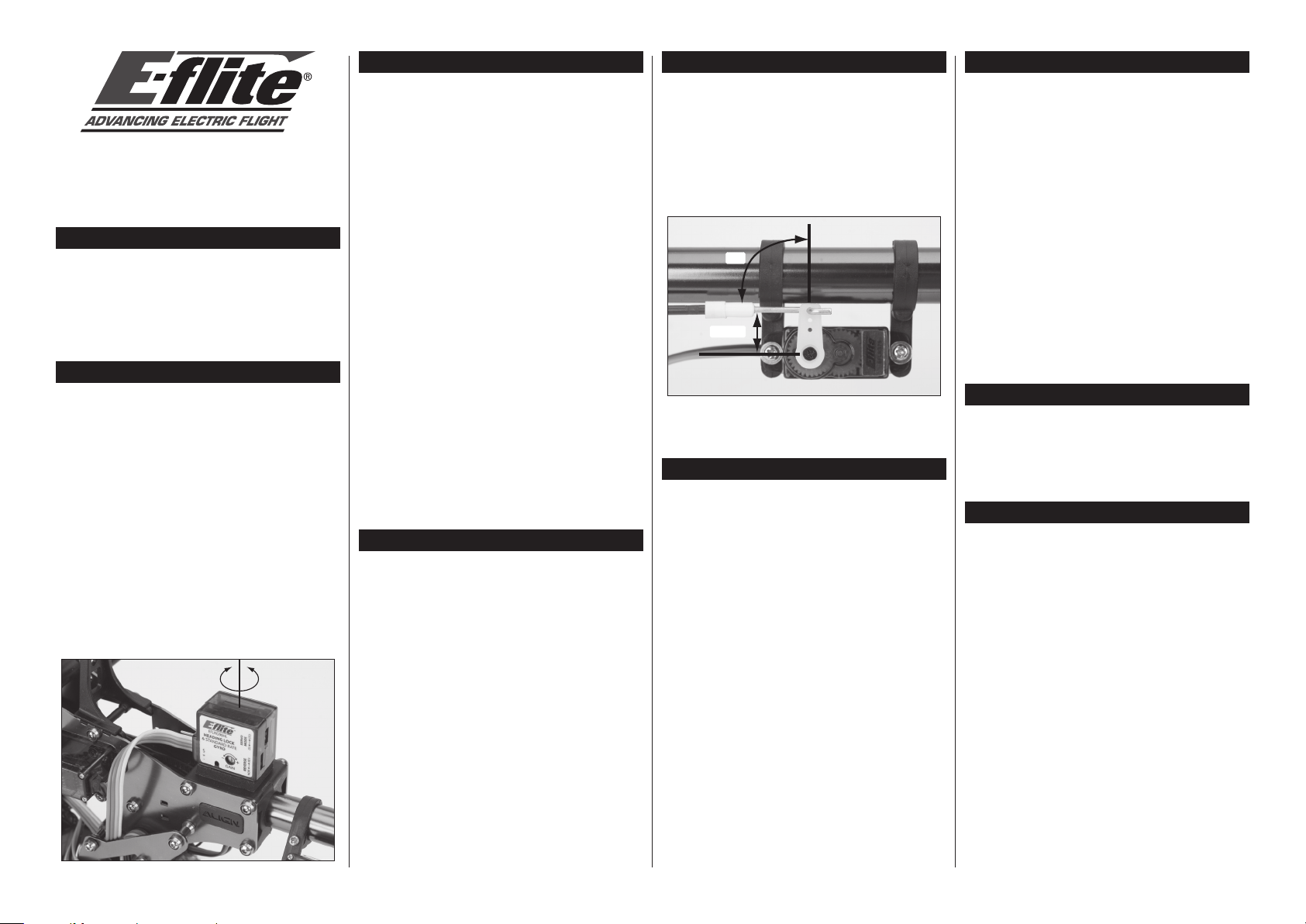
When mounting the G90, be sure the side of the gyro with
the label is mounted vertically on the model (parallel to
the main shaft). The sides of the gyro without the leads
and switches are the top and bottom respectively. Also,
be sure to position the gyro so you can easily access the
gain setting adjustment pot (if not using the remote gain
adjustment option), reversing and servo mode switches.
Once you have found a suitable location, use a small amount
of isopropyl alcohol to clean the mounting area and gyro
where the foam mounting tape will be attached. Then,
use the included foam mounting tape to mount the gyro
securely on the model. It is important to use foam mounting
tape only as it helps to prevent vibration from adversely
affecting the performance and operating life of the gyro.
Gyro Connection(s) to Receiver
Single Mode Connection (Heading Lock Mode Only)
If you will not be utilizing the dual remote gain adjustment
and mode selection option to control gain values and mode
type from an auxiliary channel on the transmitter, it will only
be necessary to connect the Rudder Channel Lead of the gyro
(the connector with three wire leads) to the rudder channel
on the receiver. You will not need to connect the Auxiliary
Channel Lead of the gyro (the connector with one wire lead)
to the receiver, however, to be certain to secure it so it cannot
come into contact with any moving parts on the helicopter.
With just the rudder channel lead of the gyro connected
to the receiver, the gyro will operate in Heading Lock
Mode only. The gain value will then be adjusted using
the Gain Setting Adjustment Pot located on the gyro.
Dual Mode Connections
(Heading Lock and Standard Rate Mode)
If you have chosen to utilize the dual remote gain adjustment
and mode selection option to control gain values and mode type
from an auxiliary channel on the transmitter, it will be necessary
to connect the Rudder Channel Lead of the gyro (the connector
with three wire leads) to the rudder channel on the receiver,
and the Auxiliary Channel Lead of the gyro (the connector with
one wire lead) to the channel on the receiver that will be used
for controlling the gyro from the transmitter. For most radio
systems, it will be best to connect the Auxiliary Channel Lead
of the gyro to Channel 5 (also known as the Gear Channel) on
the receiver, ensuring the yellow wire lead is oriented properly
so it is plugged into the “signal” side of the receiver’s pins.
With both the rudder channel and auxiliary channel leads of
the gyro connected to the receiver, the gyro can be operated
in either the Heading Lock or Standard Rate Mode. Mode
selection and gyro gain settings will then be adjusted using
an auxiliary channel on the transmitter, and the Gain Setting
Adjustment Pot located on the gyro will be disabled.
Tail Servo Selection
Selection of a suitable tail servo is critical for obtaining
maximum performance from the gyro. A servo with
quick transit times (.15 sec/60° or faster) is preferred,
and will allow the G90 to perform to its full potential.
We suggest using the following servos in
their recommended applications:
®
• E-flite
• E-flite S75 Sub-Micro Servo (EFLRS75)
• JR 3400G Mini Digital Heli Gyro Servo (JRPS3400G)
S60 Super Sub-Micro Servo (EFLRS60)
– For sub-micro and micro helicopters
– For micro and mini helicopters
– For mini helicopters
Servo Arm and Pushrod Setup
After installing your chosen servo on the model, it will be best
to center the servo electronically using an open channel before
installing the servo arm and connecting the servo to the G90.
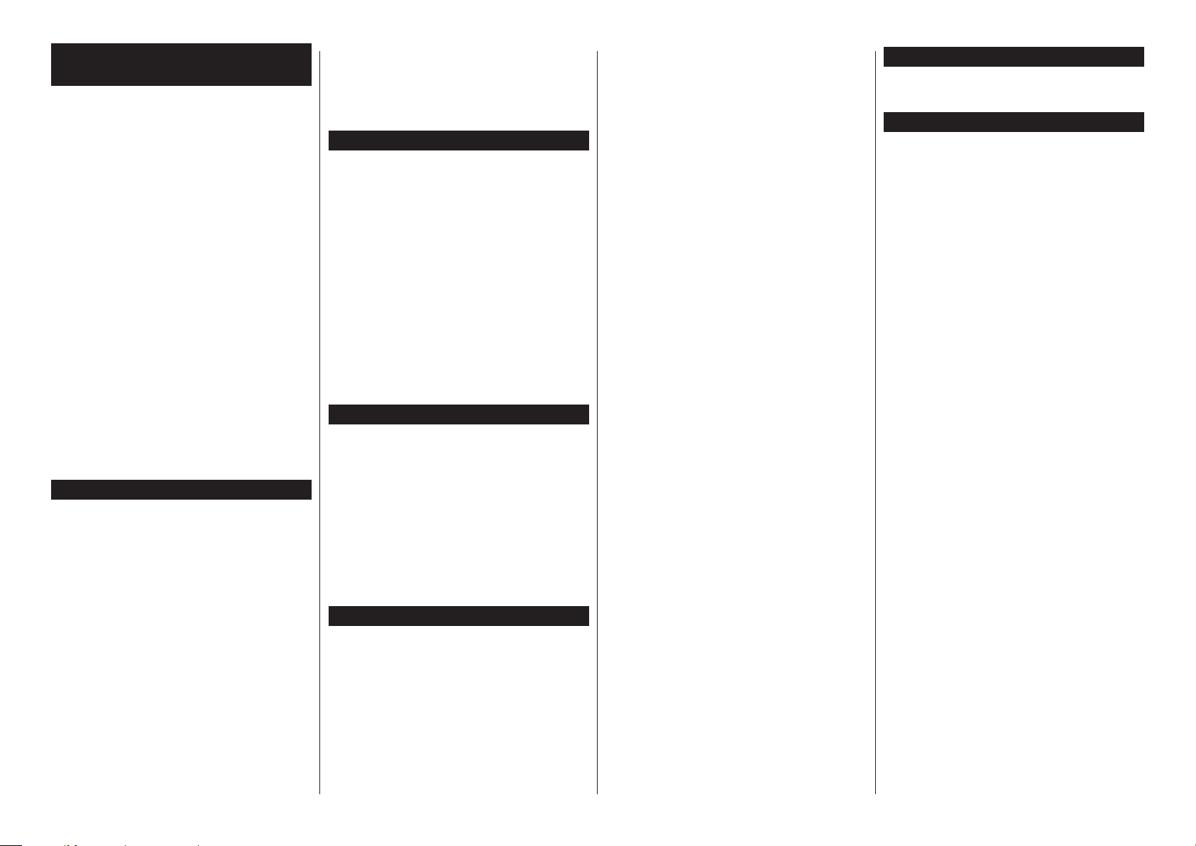
Once you have centered the servo electronically, choose a
servo arm that allows the tail rotor pushrod linkage or linkage
ball to be positioned approximately 8–11mm (typical for T-REX
and similar models) from the center of the servo’s output
gear/shaft. Then, install the servo arm on the servo, ensuring
it is perpendicular to the tail rotor pushrod linkage when in the
centered/neutral position. Also, be sure to remove any unused
portions of the servo arm to prevent any binding or obstruction.
After installing the tail rotor pushrod linkage on the tail servo
arm, and ensuring the tail servo is still centered electronically,
adjust the length of the pushrod so the tail pitch slider is centered
on the tail rotor shaft, between the tail case and tail hub.
Servo Connection to Gyro
Once the tail servo, servo arm and linkage have been installed
on the model, it will be necessary to connect the servo to
the G90. Connect the servo lead to the servo connection
on the gyro (the three pins exiting the gyro case), ensuring
proper orientation and polarity direction of the wire leads
by following the markings on the label of the gyro:
S = Signal wire lead connection location
+ = Positive wire lead connection location
– = Negative wire lead connection location
Servo Mode Setting
Standard (STD) Servo Mode
If you are using an analog servo (like the E-flite S60 or
S75), be sure the Servo Mode switch located on the side of
the gyro is set to the Standard (STD) position for the best
possible performance. If it is set to the Digital Servo (DS)
position, the analog servo may not operate correctly and/or
will be damaged due to the high frame rate output of the gyro
when it is in the Digital Servo Mode. Do not use analog
servos with the gyro set for Digital Servo Mode.
Digital (DS) Servo Mode
If you are using a digital servo (like the JR 3400G), be sure the
Servo Mode switch located on the side of the gyro is set to the
Digital Servo (DS) position for the best possible performance.
In the Digital Servo Mode, the gyro sends inputs to the servo at
a much higher rate than when in the Standard Servo Mode for
added performance and holding power. However, you must be
sure to use a digital servo that is capable of handling an input
pulse rate of 275Hz or higher (like JR and similar digital servos),
or the servo will not operate correctly and/or will be damaged
due to the high frame rate output of the gyro when it is in the
Digital Servo Mode. Do not use digital servos that cannot
handle an input pulse rate of at least 275Hz, or analog
servos, with the gyro set for Digital Servo Mode.
Initial Transmitter Settings
After completing installation and connection of the G90 and
tail servo on the model, please proceed with confirming
the following initial settings in your transmitter:
• Set the rudder channel trim and subtrim (if available) to neutral
• Disable and inhibit any forms of Revolution (Revo) Mixing
Initializing the Gyro
Once you have confirmed the initial settings in the
transmitter, it will be necessary to power up and
initialize the gyro before proceeding with some of
the following setup and adjustment steps:
• Power the transmitter on first.
• Then, power the receiver and gyro on.
• After powering on the receiver and gyro, make
sure you do not move or sway the model and
allow it to remain motionless until the blue LED
on the gyro illuminates solidly, indicating the gyro
has initialized properly and is ready for use.
Note: It is extremely important you do not move or
sway the model after powering on the gyro and before
it initializes. The gyro must be allowed adequate time
to record the neutral position in order to initialize
for proper operation. If you accidentally move the
model after powering the gyro on, and before it has
initialized, power the model off and repeat the process
to power the model on and initialize the gyro properly.
Page 2
Heading Lock and Standard Rate Mode
Selection and Adjustment
If you have chosen to utilize the dual remote gain adjustment
and mode selection option to control gain values and mode
type from an auxiliary channel on the transmitter, it will now
be necessary to confirm how to select and adjust the Heading
Lock or Standard Rate Modes from your transmitter. If you
have chosen not to utilize this option, please skip to the next
section, as the gyro will always be in the Heading Lock mode.
• With the transmitter, receiver and gyro powered on,
enter the transmitter’s Travel Adjustment function
(also known as ATV or EPA). If, however, you are
using a specialized program within your transmitter
for controlling the gyro (like Gyro Sensitivity or
similar), enter into that particular function.
• Scroll to the channel being used to control the gyro. This
will be the same channel into which you have plugged
the auxiliary channel lead of the gyro into the receiver.
• Then, using the selected channel’s switch on the
transmitter, toggle the switch back and forth in order
to identify the switch position for each gyro mode.
When the gyro is in Heading Lock Mode, you will find
the tail servo will not return the neutral position after
a rudder input is given. When the gyro is in Standard
Rate Mode, the tail servo will always return to the
neutral position after a rudder input is given.
• Typically, you will find when the switch is toggled to the
positive position (+), the gyro will be in the Heading Lock
Mode. Then, when the switch is toggled to the negative
position (-), the gyro will be in the Standard Rate Mode.
• Once you have identified the switch position for each
mode, note you will be making gain adjustments to
the selected mode by changing the Travel Adjustment
(ATV/EPA) value for its given switch position.
Initial Gain Settings and Adjustment
Single Mode (Heading Lock Mode Only)
When utilizing the Single Mode option (Heading Lock Mode
only), you will make adjustments to the gyro gain value by
using the Gain Setting Adjustment Pot located on the gyro
itself. Use a small flat blade screwdriver and extreme care (to
prevent damage to the pot) to adjust the position of the pot.
When the pot is in the fully counterclockwise position (-), the
gain value will be approximately 0%. When the pot is in the full
clockwise position (+), the gain value will be approximately 100%.
We suggest a setting of approximately 50% (pot in the middle
position) for the first test flight after installing the gyro.
Dual Mode (Heading Lock or Standard Rate Mode)
When utilizing the Dual Mode option (Heading Lock or Standard
Rate Mode selectable), you will make adjustments to the gyro
gain value in each mode remotely from the transmitter, using
the auxiliary channel you have selected for gyro control.
Depending on the transmitter and channel used to control the
gyro, you may have the ability to set the Travel Adjustment
(ATV/EPA) value from 0% to approximately 100%, or even up to
150%. This is not a problem, as long as you note the maximum
value you can set for travel adjustment will equal an actual
gain value of 100% for the gyro. In the case of a transmitter
and channel that allows you to set the travel adjustment value
up to 150%, you will achieve approximately 50% gyro gain
value at a travel adjustment value of 75%, and approximately
100% gyro gain value at a travel adjustment value of 150%.
We suggest setting the gyro gain value to approximately
50% in both the Heading Lock and Standard Rate Modes
for the first test flight after installing the gyro.
Confirming Gyro/Servo Operating Direction
It will now be necessary to confirm the tail servo and gyro are
operating in the correct directions for proper control. First, refer
to the instruction manual included with your helicopter model
for information regarding the direction in which the tail servo
should respond to rudder inputs for proper control response.
After confirming the tail servo is responding in the correct
direction to rudder inputs, you will also need to confirm the
gyro is responding properly to movements of the helicopter,
while providing proper inputs to the tail servo in order to
counteract any unwanted changes in yaw. To do this, view the
servo arm (from the top of the servo) and note the direction the
arm moves (clockwise or counterclockwise) when you give a
right rudder input on the transmitter (while the model remains
motionless). Then, yaw the nose of the helicopter quickly to
the left, while again noting the direction the tail servo arm
moves. The arm should move in the same direction as it did for
a right rudder command, helping to counteract the left-hand
yaw movement of the nose. If the arm moves in the opposite
direction, switch the Reverse switch located on the side of the
G90 to its opposite position. Then, repeat the steps above to
confirm the gyro is now operating in the correct direction.
Trimming Neutral with Sub-Trim and Trim
When in Heading Lock Mode, the tail servo arm may “creep” or
move while the model remains motionless, and with no rudder
input from the transmitter. This movement is normal, but can
be minimized by adjusting the sub-trim (preferred, if available)
or trim value of the rudder channel in/on your transmitter. Use
the sub-trim function or trim lever on the transmitter to add a
left or right value to the rudder channel. Then, re-center the tail
servo arm with the control stick and watch for any additional
movement. Add or reduce the sub-trim or trim value as needed
until the tail servo arm moves as little as possible when near
the neutral position. In general, only a small amount of subtrim or trim adjustment will be required in order to minimize
movement of the tail servo arm (and “drifting” of the nose/tail of
the helicopter model in flight), and some very slow movement
that may still remain after making the adjustments is normal.
Adjustments After Test Flights
Once you have completed installation and setup of the
G90, it will be necessary to conduct test flights in order
to identify any settings that must be adjusted so that you
can obtain maximum performance of the gyro. Be careful
when conducting the initial test flight, however, taking your
time to ensure the gyro and tail servo are responding and
performing properly before lifting the model into the air.
Gain Adjustments
During the test flight(s), establish a stable hover and apply some
short and quick rudder inputs while observing the reaction of
the tail when the control stick is returned to its neutral position.
If there is any tendency for the tail to twitch quickly (oscillate)
from side to side, it will be necessary to lower the gyro gain
value. You can do this by adjusting the Gain Setting Adjustment
Pot on the gyro itself counterclockwise a small amount (if using
the Single Mode option), or remotely from the transmitter by
reducing the Travel Adjustment (ATV/EPA) value for the gyro
control channel (if using the Dual Mode option). The goal,
when in Heading Lock Mode, is to find the highest gyro gain
value at which the tail of the helicopter will not oscillate in all
areas of flight, including fast forward flight and descents.
If you are using the Dual Mode option, you will also need to
adjust the gyro gain value for the Standard Rate Mode. In this
mode, the amount of gyro gain value required will typically
depend most on the flying style and preference of the pilot.
Tail Linkage and Pushrod Adjustments
If, after conducting test flights, you find the gyro gain value cannot
be set high enough to cause some oscillation of the tail (even at
the highest setting), it will be necessary to adjust the position of
the tail rotor pushrod linkage on the tail servo arm. In this case,
you will need to move the linkage farther out from the center of
the servo’s output gear/shaft (by approximately 2mm to start).
If you find the gyro gain value cannot be set low enough to
prevent oscillation of the tail (when near the lowest setting),
it will be necessary to adjust the position of the tail rotor
pushrod linkage on the tail servo arm. In this case, you will
need to move the linkage closer to the center of the servo’s
output gear/shaft (by approximately 2mm to start).
If you are using the Dual Mode option, and will be switching
between the Heading Lock and Standard Rate Modes during flight,
it is best to mechanically adjust the tail rotor pushrod length so
there is not a significant difference in the rudder trim/sub-trim
values required in each mode for the best performance. This
can be accomplished by flying the model in the Standard Rate
Mode and adjusting the length of the pushrod so the nose/tail of
the model stays as straight as possible, with no rudder input or
rudder trim/sub-trim values that are significantly different than
those set for optimum performance in the Heading Lock Mode.
Rudder Trim Adjustments
During flight, it may be necessary to make some small
adjustments to the rudder trim position/value in order to help
prevent the nose/tail of the model from “drifting” to the left or
right when the rudder stick is in the neutral position. Typically,
only a small amount of adjustment may be necessary.
Rudder Travel Adjustments and Exponential
By increasing or decreasing the left and right Travel Adjustment
(ATV/EPA) values for the rudder channel in your transmitter,
you can adjust the rate at which the model will pirouette when
a full rudder input is given and held, and responds to rudder
inputs in general. You can also further fine-tune response of
the tail around neutral by increasing or decreasing the amount
of Exponential (if available) used for the rudder channel.
Temperature and Environmental Conditions
It is always best to avoid sudden temperature and
environmental condition changes when using a gyro. For
example, it is best to not fly a model on a very hot day
immediately after removing it from an air-conditioned vehicle.
It is also best to keep the gyro out of direct sunlight and
away from any heat generating sources on the model.
To help the gyro better adapt to temperature and environmental
conditions at the flying field, it is best to let the model
stand for approximately 10-15 minutes before flying,
allowing the temperature inside the gyro to stabilize.
Limited Warranty Period
Horizon Hobby, Inc. guarantees this product to be
free from defects in both material and workmanship
for a period of 1 year from the date of purchase.
Limited Warranty & Limits of Liability
Pursuant to this Limited Warranty, Horizon Hobby, Inc. will,
at its option, (i) repair or (ii) replace, any product determined
by Horizon Hobby, Inc. to be defective. In the event of
a defect, these are your exclusive remedies.
This warranty does not cover cosmetic damage or damage due
to acts of God, accident, misuse, abuse, negligence, commercial
use, or modification of, or to any part of the Product. This
warranty does not cover damage due to improper installation,
operation, maintenance, or attempted repair by anyone other than
an authorized Horizon Hobby, Inc. service center. This warranty
is limited to the original purchaser and is not transferable. In
no case shall Horizon Hobby’s liability exceed the original cost
of the purchased product and will not cover consequential,
incidental or collateral damage. Horizon Hobby, Inc. reserves
the right to inspect any and all equipment involved in a warranty
claim. Repair or replacement decisions are at the sole discretion
of Horizon Hobby, Inc. Further, Horizon Hobby reserves the
right to change or modify this warranty without notice.
REPAIR OR REPLACEMENT AS PROVIDED UNDER
THIS WARRANTY IS THE EXCLUSIVE REMEDY OF THE
CONSUMER. HORIZON HOBBY, INC. SHALL NOT BE LIABLE
FOR ANY INCIDENTAL OR CONSEQUENTIAL DAMAGES.
As Horizon Hobby, Inc. has no control over use, setup, final
assembly, modification or misuse, no liability shall be assumed
nor accepted for any resulting damage or injury. By the act of
use, setup or assembly, the user accepts all resulting liability.
If you as the purchaser or user are not prepared to accept
the liability associated with the use of this product, you
are advised to return this product immediately in new
and unused condition to the place of purchase.
For additional information concerning the Limited Warranty,
Limits of Liability and Safety Precautions, please refer to our web
page for this item or contact your E-flite distributor. You can also
direct emails to productsupport@horizonhobby.com, or in the
U.S., call 877.504.0233 toll free to speak to a service technician.
© 2006 Horizon Hobby, Inc.
www.horizonhobby.com
www.E-fliteRC.com
E-flite® is an exclusive brand of Horizon Hobby, Inc.
#9231
 Loading...