

Page 1

LaserSense Nano
A
spirating Smoke Detector
Installers Handbook
P/N 9-14564 (EN) • REV 02 • ISS 11ABR13
Page 2

Copyright © 2013 UTC Fire & Security. All rights reserved.
Manufacture
r
Kidde Products Limited
Unit 2, Blair Way, Dawdon
Seaham, County Durham
SR7 7PP
United Kingdom
Certification
0832
0832-CPD-1312
EN 54-20: 2006
Aspirating smoke detectors for fire detection and fire alarm systems
for buildings.
Class A, B, and C
Technical data: See INF48022 and INF48023 held by the
manufacturer.
Contact information For contact information, see www.airsensetechnology.com.
Page 3

LaserSense Nano Aspirating Smoke Detector Installers Handbook i
Content
Important information ii
Advisory messages iii
EN 54-20 compliance iv
Chapter 1 Product and component descriptions 1
Introduction 2
Available software for the detector 2
Specifications 3
Indicators 4
Chapter 2 Installation and configuration 7
Introduction 8
Antistatic precautions 8
System design 9
Installation 16
Configuration 23
Chapter 3 Commissioning 27
Introduction 28
Precommissioning preparation 28
Commissioning checklist 28
Chapter 4 Troubleshooting 33
Troubleshooting the detector 34
Chapter 5 Maintenance 37
Introduction 38
Scheduled maintenance 38
Maintenance procedures 39
Appendix A Communications card and APIC 43
Optional communications card 44
Optional APIC 47
Glossary 49
Index 51
Page 4

ii LaserSense Nano Aspirating Smoke Detector Installers Handbook
Important information
Regulatory information
This equipment is Class III as defined in EN 60950 (i.e., this equipment is
designed to operate from Safety Extra Low Voltages and does not generate any
hazardous voltages).
As this equipment is part of a fire detection system, input power should be
supplied from an approved power supply conforming to EN 54-4 or UL/ULC and
FM standards.
This product has been designed to meet the following requirements:
• NFPA 72 National Fire Alarm and Signaling Code
• UL 268 Smoke Detectors for Fire Alarm Signaling Systems
• UL 268A Smoke Detectors for Duct Applications
• UL 864 Control Units for Fire Protective Signaling Systems
• CAN/ULC-S524 Installation of Fire Alarm Systems
• ULC-S527 Control Units for Fire Alarm Systems
• CAN/ULC-S529 Smoke Detectors for Fire Alarm Systems
System reacceptance test after reprogramming (UL/ULC and FM): To ensure
proper system operation, this system must be retested in accordance with
NFPA 72 after any programming change. Reacceptance testing is also required
after any addition or deletion of system components, and after any modification,
repair, or adjustment to system hardware or wiring.
Limitation of liability
To the maximum extent permitted by applicable law, in no event will UTCFS be
liable for any lost profits or business opportunities, loss of use, business
interruption, loss of data, or any other indirect, special, incidental, or
consequential damages under any theory of liability, whether based in contract,
tort, negligence, product liability, or otherwise. Because some jurisdictions do not
allow the exclusion or limitation of liability for consequential or incidental
damages the preceding limitation may not apply to you. In any event the total
liability of UTCFS shall not exceed the purchase price of the product. The
foregoing limitation will apply to the maximum extent permitted by applicable law,
regardless of whether UTCFS has been advised of the possibility of such
damages and regardless of whether any remedy fails of its essential purpose.
Installation in accordance with this manual, applicable codes, and the instructions
of the authority having jurisdiction is mandatory.
While every precaution has been taken during the preparation of this manual to
ensure the accuracy of its contents, UTCFS assumes no responsibility for errors
or omissions.
Page 5

LaserSense Nano Aspirating Smoke Detector Installers Handbook iii
Advisory messages
Advisory messages alert you to conditions or practices that can cause unwanted
results. The advisory messages used in this document are shown and described
below.
WARNING: Warning messages advise you of hazards that could result in injury
or loss of life. They tell you which actions to take or to avoid in order to prevent
the injury or loss of life.
Caution: Caution messages advise you of possible equipment damage. They tell
you which actions to take or to avoid in order to prevent the damage.
Note: Note messages advise you of the possible loss of time or effort. They
describe how to avoid the loss. Notes are also used to point out important
information that you should read.
Product Symbols
This symbol appears on the main board of the unit and indicates that the
board contains static sensitive components.
This label is located on the laser chamber at the bottom right of the open
detector and signifies that the unit is a Class 1 Laser product as specified
in IEC 60825-1. The unit incorporates a Class 3B embedded laser which
must not be removed from the detector, as retinal damage may result if
the laser beam enters the eye.
This symbol indicates the Safety ground studs. These are for grounding
cable screens, etc., and should not be connected to 0V or signal earth.
Page 6

iv LaserSense Nano Aspirating Smoke Detector Installers Handbook
EN 54-20 compliance
The installation must be designed using PipeCAD software, which is provided
free on the CD shipped with each detector. After designing the installation
including pipes, endcaps and sampling holes, enter the detector type. To select
the detector type, select Options, select Calculation options, and then select the
detector from the Type drop-down list.
Select Options > Calculate or click on the calculator icon. The software will
prompt you to choose from Use set hole sizes, Best flow balance, or Max.
permissible transit time. Select the appropriate option, and then click OK. The
results for each pipe (View > Results) show calculations for each sampling hole
on the pipe with the nearest to the detector at the top of the screen, and the
endcap hole at the bottom.
The classification of each sampling device configuration and associated
sensitivity settings are determined by the column headed Hole sensitivity %
obs/m, which shows the predicted sensitivity for each hole. For the installation to
comply with EN 54-20 depending on the class of installation, each sampling hole
must be no less sensitive than the following:
Class A: 0.80% obs/m
Class B: 1.66% obs/m
Class C: 7.54% obs/m
The calculation can be further refined by leaving a working detector in the
protected area for at least 24 hours at the intended alarm factor for the
installation (this could be done before or after installation). The detector
sensitivity can be read from the Sensitivity figure on the histogram screen of the
Remote software supplied with each detector. Click Options > Calculation options
to open the Hole calculation options dialog box. Enter the sensitivity value
obtained from the practical test, and then click OK. The new calculated value will
use the real sensitivity from the practical test.
The PipeCAD software will determine the classification of any used configuration.
Commissioning and periodic system tests must involve smoke tests to verify that
the system performs as expected and enters Fire 1 alarm within the time
determined by PipeCAD from the farthest hole. The detector sensitivity must also
be inspected to ensure it has not radically fallen from the installed figure. If it has
changed for any reason, the new figure must be re-entered into PipeCAD and the
recalculated hole sensitivities must be confirmed to be within the class limits
shown above.
Page 7

LaserSense Nano Aspirating Smoke Detector Installers Handbook 1
Chapter 1
Product and component
descriptions
Summary
This chapter provides descriptions of the detector features, specifications, and
controls and indicators.
Content
Introduction 2
Available software for the detector 2
Specifications 3
Indicators 4
Inside the detector 5
Page 8

Chapter 1: Product and component descriptions
2 LaserSense Nano Aspirating Smoke Detector Installers Handbook
Introduction
This aspirating detector is a highly sophisticated next generation high sensitivity
aspirating smoke detection product that provides all the benefits of air sampling
high sensitivity smoke detection, including very early warning. Designed for easy
installation and commissioning, the detector incorporates a patented artificial
intelligence known as ClassiFire, which allows the detector to configure itself to
optimum sensitivity, alarm thresholds, and minimum nuisance alarms for various
environments.
This detector operates by drawing air from a protected space via a supervised
piping network in relatively small areas. The sampled air is passed through a
dust separator to remove dust and dirt before entering the laser detection
chamber. State-of-the-art electronics are used to analyse the sampled air and
generate a signal representing the level of smoke present.
ClassiFire intelligence also monitors the detector chamber and dust separator for
contamination, continually adjusting the appropriate operating parameters to
counteract the negative effects of any contamination. Aspirating smoke detectors
are unique in being able to provide a consistent level of protection in a very wide
range of environments by continuously making minor adjustments to sensitivity.
The detector can easily be installed without any specialised tools or software.
Available software for the detector
The Remote Control and the SenseNET software packages are available to
program the detector.
• Remote Control software: Provided free of charge with every detector, this
software package enables the user to set up and configure the programmable
functions of one or more detectors from a computer connected via an RS-232
serial cable.
• SenseNET software: SenseNET software is used to configure and manage a
large network of detectors with a simple, streamlined graphical user interface
from a computer connected to a detector or command module via an RS-232
serial cable to RS-485 converter interface.
Page 9

Chapter 1: Product and component descriptions
LaserSense Nano Aspirating Smoke Detector Installers Handbook 3
Specifications
Caution: This equipment is only to be used in accordance with these
specifications. Failure to operate the equipment as specified may cause damage
to the unit, injury, or property damage.
Table 1: Specifications
Specification Value
SELV rating EN 60950 Class III
Supply Voltage 21.60 to 26.40 (UL rated 22.25 to 26.40 VDC)
Current consumption 350 mA
Electrical Safety Complies with EN 610190-1
Size 190 W × 230 H × 110 D mm
(7.5 W × 9.0H × 4.3 D in.)
Weight 1.2 kg (2.65 lbs.)
Operating temperature range −10 to +60ºC (EN 54-20)
32 to 100°F (0 to 38°C) (UL 268, CAN/ULC-S529, FM)
Operating humidity range 0 to 90% relative humidity, noncondensing
EN 61010-1 Pollution degree 1
EN 61010-1 Installation category II
IP rating IP50
Sensitivity range
(%obs/ft.)
(%obs/m)
Min. = 7.62%, Max. = 0.122% FSD
Min. = 25%, Max. = 0.4% FSD
Maximum sensitivity resolution 0.4% obs/m (0.12% obs/ft.)
Detection principle Laser light forward scattering mass detection
Maximum number of sampling holes Class A: 2
Class B: 4
Class C: 10
Maximum sampling pipe length 50 m (164 ft.)
Pipe inlets 2 (sampling and exhaust pipes)
Alarm / fault relays Pre-Alarm / Alarm / Fault
Relay contact rating (changeover) 1 A at 24 VDC (resistive load)
Programming Internal DIP switches
PC interrogation Via optional communications card
APIC compatible Yes
Page 10

Chapter 1: Product and component descriptions
4 LaserSense Nano Aspirating Smoke Detector Installers Handbook
Indicators
Figure 1 below shows the indicators on the detector.
Figure 1: External components
Alarm
Pre-Alarm
Fault
OK
Flow
Filter
Laser
(1)
(2)
(3)
(4)
(5)
(6)
(7)
(8)
(1) Alarm: Illuminates to indicate that the smoke level has passed the detector’s Fire 1 threshold,
and the normally open ALARM relay contacts have closed.
(2) Pre-Alarm: Illuminates to indicate that the smoke level has passed the detector’s Pre-Alarm
threshold, and the normally open PRE-ALARM relay contacts have closed.
(3) Fault: Illuminates to indicate a fault condition and that the normally closed FAULT relay
contacts have opened. Three additional LEDs indicate the type of fault.
If the Fault LED is illuminated but none of the additional LEDs are lit, it indicates a problem
with the power supply if its fault output is connected to the detector’s INPUT terminals and
DIP switch 7 is set to OFF (its default position). Alternatively, this can happen if the INPUT
terminals are left open circuit and DIP switch 7 is OFF.
(4) OK: Illuminates to confirm normal operation.
During initial setup, the OK LED will flash for 15 minutes while the detector learns its
operating environment. This does not indicate a problem with the detector.
(5) Flow: Illuminates to indicate an airflow fault. This may be due to blocked or broken pipes,
although it can also occur if, for example, factory warehouse doors are opened on a windy
day, a large pressure change occurs, or if industrial air conditioning turns on. Another
possible cause is that the aspiration fan connection cable is damaged or disconnected.
(6) Filter: Illuminates to indicate that the detector’s air filter needs to be changed.
(7) Laser: Illuminates to indicate a problem with the detector laser chamber, as might be caused
by the laser head connecting cable is damaged or disconnected. It can also be caused by
certain kinds of internal systems faults, which appear in the detector’s event log as “process
errors.”
(8) Front cover securing screw: Leave sufficient clearance below the detector to allow
screwdriver access to this screw.
Page 11

Chapter 1: Product and component descriptions
LaserSense Nano Aspirating Smoke Detector Installers Handbook 5
Inside the detector
Figure 2
below shows the main interior parts of a detector with the cover off.
Figure 2: Internal components
(1) Two holes for conduit connection. There are two 3/4 in. drilling guides provided on the top of
the detector and one on the bottom providing holes for conduit.
(2) Pipe entries provide a connection for 3/4-inch pipe. A 3/4 in. male to 25 mm female adapter
is required when using larger than 1 inch (27 mm) O.D. pipe.
Note: Do not glue pipes into the detector to allow for future removal.
(3) Aspirating fan connector lead: If this lead is broken or not connected, the fan will not turn and
the detector will indicate a FLOW fault.
(4) Main PCB: No user-serviceable parts.
The PCB is fixed in place with 5 M3 x 6 screws. The detector should not be operated with
any of the screws missing, as this could cause air leaks and unreliable operation.
(5) Power supply connection terminals
(6) Volt-free relay contact terminals
(7) DIP switch: Used to configure user-selectable detector functions.
(8) Input switch terminals
(9) Ribbon cable connection for optional communication card or APIC card
(10) Optional communication terminals: used when the optional communication card is fitted to
connect the RS-485 network
Page 12

Chapter 1: Product and component descriptions
6 LaserSense Nano Aspirating Smoke Detector Installers Handbook
(11) Detector laser head ribbon connector: If this lead is broken or not connected, the detector
will indicate a HEAD Fault.
(12) Detector laser head assembly: No user-serviceable parts. Do not remove this from the
detector, due to the risk of exposure to the laser.
(13) Detector laser head cover plate: This protects the laser head. The plate should not be
removed from the detector.
(14) Replaceable dust filter: This simply slides in and out of its mounting. The separator and its
replacement have IN written in red on one side, and OUT on the other to indicate correct
orientation.
(15) Three mounting holes to mount the detector. Use #10-24 pan-head screws for mounting.
Note: Ensure that the detector is fixed to a flat surface so that the enclosure will not twist and
become damaged.
Page 13

LaserSense Nano Aspirating Smoke Detector Installers Handbook 7
Chapter 2
Installation and
configuration
Summary
This chapter provides information necessary to install and configure the detector
system.
Content
Introduction 8
Antistatic precautions 8
System design 9
Sample pipe networks 10
Air handling unit installation 10
Below or above the ceiling installations 11
Return air duct sampling method 13
Return air grill sampling method 15
Installation 16
Installation guidelines 16
Removing the front cover 17
Mechanical installation 17
Electrical installation 19
Configuration 23
Final installation 25
Removing the detector 25
Page 14

Chapter 2: Installation and configuration
8 LaserSense Nano Aspirating Smoke Detector Installers Handbook
Introduction
This chapter provides information necessary to install the Nano detector system.
Installation consists of the following steps:
1. Unpack the shipping carton. Ensure that the package contains product
literature, one ferrite ring, and the detector.
2. Determine the optimum location for the detector.
3. Mount the detector into the selected location.
4. Connect the detector to the sampling pipe network.
Installation should only be done by factory-trained technicians.
Installation should be in accordance with applicable installation requirements.
These include:
• NFPA-70, National Electrical Code
• NFPA-72, National Fire Alarm and Signaling Code
• CSA C22.1 Canadian Electrical Code, Part 1
• CAN/ULC-S524 Installation of Fire Alarm Systems
• Any other local, national, or installation requirements or standards.
WARNING: Electrocution hazard. All connections should be made with the
power turned off.
Antistatic precautions
This system contains static-sensitive components. Always ground yourself with a
proper wrist strap before handling any circuits.
Caution: When handling any electric components or printed circuit boards,
antistatic precautions must be followed. Failure to do so may result in component
damage.
Static discharge can be reduced by adhering to the following guidelines:
• Always use conductive or antistatic containers for transportation and storage,
if returning any item.
• Wear a wrist strap while handling devices and ensure that a good ground is
maintained throughout the installation process.
• Never subject a static sensitive device to sliding movement over an
ungrounded surface and avoid any direct contact with the pins or
connections.
• Avoid placing sensitive devices onto plastic or vinyl surfaces.
• Minimize the handling of sensitive devices and printed circuit boards (PCBs).
Page 15

Chapter 2: Installation and configuration
LaserSense Nano Aspirating Smoke Detector Installers Handbook 9
System design
Pre-engineered piping designs simplify the installation of the detector pipe
network. The following criteria ensure that the airflow and transport times are
within the design of the detector. The design parameters listed below must be
adhered to for all pre-engineered pipe designs. Pre-engineered piping
networks should not exceed the transport time requirement of 120 seconds.
During the system test, transport times are often less than 55 seconds.
• The maximum of three elbows and one pipe tee can be used in any pipe
network design.
• When using a pipe tee, it must be located within 20 feet of pipe from the
detector.
• All capillary tubes will have a maximum length of 3 feet and use a 9/64 inch
sampling hole size.
• The first sampling hole must be 10 feet or more from the detector.
• The use of sampling capillary tubes and sampling holes can be mixed in any
combination on the pipe network.
• On branch designs, the same number of sampling holes must be used on
each branch.
Table 2: Sample pipe network parameters
Total pipe
length
Max amount
elbows
Max sampling
points
Sampling
hole size
Capillary tube
sample hole size
End cap
hole
164 feet 3 10 1/8 inch 9/64 inch 5/32 inch
Note: PipeCAD pipe modeling software is used to design pipe networks outside
the above parameters. Refer to the PipeCAD System Design and Installation User
Manual for complete instructions.
The Nano detector employs a fan designed to detect smoke in relatively small
areas. The Nano detector is
not
intended to protect large areas, or to sample from
areas where there may be any difference in airflow rates or pressure
differentials. If detection in environments conforming to these descriptions is
required, other type detectors should be used.
Always locate the sampling points in positions to which smoke may reasonably be
expected to travel. It is usually better to locate the sampling pipe directly in the
airflow (for example, across the return air register of an air conditioning unit).
Note: There is no substitute for carrying out smoke tests prior to installation of
pipework to indicate suitable sampling point location.
Page 16

Chapter 2: Installation and configuration
10 LaserSense Nano Aspirating Smoke Detector Installers Handbook
Sample pipe networks
Simple designs with short sampling pipes produce the best results. Maximum
allowed sampling pipe length is 164 feet (50 meters) in still air. In areas or
applications where the external airflow rate is greater than 3 feet per second
(1 meter per second), the maximum sampling pipe length is reduced to 33 feet
(10 meters).
Air handling unit installation
No more than one air handling unit may be protected with one Nano detector.
In this application, ensure that the sampling pipe is raised clear of high velocity
air in the immediate vicinity of the air intake grill on standoff posts as shown in
Figure 3 below.
Figure 3: Air handling unit in vicinity of the Nano detector (exhaust pipes not shown for
clarity)
(1)
(2)
(3)
(4)
(5)
(6)
(7)
(8)
(9)
(3)
(1) Incorrect
(2) Detector
(3) Sampling pipe
(4) Standoff posts
(5) Correct
(6) Detector
(7) AHU
(8) Equipment cabinet
(9) Direction of smoke
Page 17

Chapter 2: Installation and configuration
LaserSense Nano Aspirating Smoke Detector Installers Handbook 11
Below or above the ceiling installations
The Nano detector is supplied with an exhaust port (see Figure 2 on page 5).
This allows the Nano detector to sample from areas which may be at different
air pressure from the detector location. Typical uses are for air-duct sampling and
allowing the installation of the detector in under-floor or ceiling voids or when
sampling from pieces of computer related equipment. See Figure 4 below and
Figure 5 on page 12.
Figure 4: Installation of pipework above ceiling with exposed detector (piped exhaust)
(1)
(3)
(4)
(2)
(5)
(1) Sampling pipe
(2) Sampling hole
(3) Exhaust pipe
(4) Detector
(5) False ceiling
Page 18

Chapter 2: Installation and configuration
12 LaserSense Nano Aspirating Smoke Detector Installers Handbook
Figure 5: Installation with detector mounted in ceiling void (no exhaust piping)
(1)
(2)
(4)
(3)
(1) Sampling pipe
(2) Sampling hole
(3) Detector
(4) False ceiling
Page 19

Chapter 2: Installation and configuration
LaserSense Nano Aspirating Smoke Detector Installers Handbook 13
Return air duct sampling method
Duct sampling generally is the most cost-effective method of air sampling
because the pipe runs are minimal and a single detector may be used to cover a
larger area. The speed of response of the detector to smoke is given by the
exchange rate in the rooms ventilated by the duct ventilation system. This tends
to be rapid, giving early warning of any smoke present. This type of sampling is
particularly suited to aspirated smoke detection, since the smoke content in the
air will tend to be diluted to a level below that of point type detectors. Also, the
relatively high airflow in the duct reduces the effectiveness of point-detection
devices.
The duct sampling method does have one major disadvantage. If the ventilation
becomes inoperative, the air-flow through the duct system ceases and the
smoke-detection system becomes ineffective.
Figure 6: Return air duct sampling
(1) 1/4 to 1/3 of duct width
(2) 45 degree
(3) 11.81 in. (300 mm) minimum
(4) 45 degree
(5) 2/3 to 3/4 of duct width
(6) Direction of air flow
(7) Intake pipe to detector
(8) Exhaust pipe from detector
Figure 6 above shows a typical sampling pipe arrangement for an air duct. The
right pipe is the sampling pipe and the holes on it are drilled 4 inches apart and
face into the oncoming air stream. The left pipe exhausts air from the detector.
The detector is UL 268A and CAN/ULC-S529 approved for duct applications with
an operating air velocity range of 300 to 4000 ft./min (1.52 to 20.32 m/sec).
The following guidelines apply:
• Only one duct can be monitored per detector.
• If the air sampling pipe system and aspirating detector is used as the primary
smoke detection system, methods should be employed to notify stoppage of
airflow in the ducts.
Page 20

Chapter 2: Installation and configuration
14 LaserSense Nano Aspirating Smoke Detector Installers Handbook
• The exhaust air from the detector must be returned back to the duct using an
exhaust-port adapter and associated piping. This requirement assures
positive airflow through the detector.
• Locate sampling pipe in the main supply duct return side, downstream of the
filters and a minimum of six duct widths from any source of turbulence (such
as bends, inlets, or deflection plates) to reduce the effects of stratification. In
installations where the filter is capable of removing smoke, install the
sampling tube upstream of the filter.
Note: Where it is physically impossible to locate the sampling pipe in
accordance with this guideline, the sampling pipe may be positioned closer
than six duct widths, but as far as possible from inlets, bends, or deflection
plates.
• Locate the sampling pipe such that dampers do not restrict airflow at the
sampling pipe.
• The sampling pipe should be located before air exhausts from the building or
before diluting return air with outside air.
• For accurate identification of the source of an alarm, locate sampling pipe as
close as possible to the protected area's air entry into the duct system.
• Locate sampling pipe on the downstream side of the filter to sense fire in the
filters.
Note: If filters are blocked, sufficient airflow may no longer be present for
proper operation.
• Do not locate sampling pipe near outside air inlets except to monitor smoke
entry to the handling system for adjacent areas.
• Whenever possible, locate sampling pipe upstream of air humidifiers and
downstream of dehumidifiers.
Note: Deviation from these recommended guidelines may reduce the
performance of your air sampling pipe system and detector.
Page 21

Chapter 2: Installation and configuration
LaserSense Nano Aspirating Smoke Detector Installers Handbook 15
Return air grill sampling method
Return air grill sampling systems are designed with sampling pipes centered in
the front of the return air grill. Sampling holes should be spaced so that a minimum
of three holes are used for each grill. Larger grills require more sampling holes.
The sampling holes should be in the direction of the airflow with an end cap.
When using the air grill sampling without another sampling method, the smokedetection system will be ineffective when the ventilation system is inoperative. If
this method is being used as the primary smoke detection system, the grill should
be monitored for stoppage of airflow.
Figure 7 below shows a typical mounting to stand sampling pipe away from high
velocity low pressure air at the entrance to the return air grill.
Figure 7: Return air grill sampling method
(1) Air flow
(2) Self tapping screws
(3) Return air grill
(4) Standoff post
(5) Sampling holes
Page 22

Chapter 2: Installation and configuration
16 LaserSense Nano Aspirating Smoke Detector Installers Handbook
Installation
Installation guidelines
The following is a brief set of guidelines on installing detectors:
• The detector should normally be mounted at a level where there is easy
access.
• The exhaust air from the unit must not be impeded in any way. If the detector
is mounted in a different air pressure from where the air is being sampled (for
example an air duct), then a pipe must be routed from the exhaust port back
to the same air pressure zone as the sampling holes.
• All wiring must comply with NEC, NFPA 70, CSA C22.1, local codes and
standards, and the requirements of the local AHJ. All signal cables must be
suitable for the application.
• The detector must not be placed in areas where either the temperature or
humidity is outside the specified operating range.
• The detector should not be placed in close proximity to any equipment
expected to generate high radio frequency levels (such as radio alarms) or
units generating high levels of electrical energy (such as large electric motors
or generators).
Table 3 on page 17 contains a list of procedural guidelines for installation of the
Nano detector.
Page 23

Chapter 2: Installation and configuration
LaserSense Nano Aspirating Smoke Detector Installers Handbook 17
Table 3: Procedural guidelines
Do Don’t
• Ensure that the ClassiFire alarm factor
is appropriately set.
• Ensure that the power and signal cables
are correctly connected before powering
up by use of cable identifiers or electrical
continuity checks. Incorrect connection
could damage the detector.
• Ensure that cable of an appropriate
approved type is used for interconnection.
• Place sampling points so that the
detector will be able to detect smoke at the
earliest opportunity.
• Ensure that the detector exhaust is in an
area with the same atmospheric
pressure as the sample pipes, either by
placing the detector physically in the
protected area or by leading a pipe from the
detector exhaust to the protected area.
• Ensure that the environment of the
protected area is within the environmental
operating parameters of the detector.
• Ensure the detector is properly
grounded.
• Remove or connect boards when the
detector is powered up.
• Attempt to adjust or alter detector
settings other than via the userprogrammable functions. Any attempts
to adjust the laser potentiometer are
detectable and will void the warranty on the
product.
• Drop the detector or use excessive force
when fitting sampling pipes as this may
damage the detector.
• Connect internal 0 volt terminals to local
earth.
• Use sampling pipe of less than 1 inch
(27 mm) outside diameter without a
suitable 1-inch (27- mm) pipe adapter. It
is important that there are no leaks where
the pipe connects to the detector.
• Place the detector so close to other
equipment that there is insufficient room
to access and change the dust separator
(filter) or access the RS-232 connector (if
installed).
• Install the detector near high power RF
sources or in damp or exposed areas.
• Attempt to re-use dust separator (filter)
cartridges once removed.
Removing the front cover
To remove the front cover, unfasten the cover securing screw located on the
bottom of the unit. The cover may then be removed.
Mechanical installation
Refer to “Inside the detector” on page 5 for conduit, pipe interface information,
and mounting hole locations.
The detector is connected to the installed sampling pipework and fixed to the
mounting surface using three screws of a type appropriate to the mounting
surface. Ensure that the sampling and exhaust pipes are securely seated in the
pipe ports before securing. If using a piped exhaust connection, be sure that the
sampling and exhaust pipe are fitted into the relevant port as shown in Figure 8
on page 18.
Page 24

Chapter 2: Installation and configuration
18 LaserSense Nano Aspirating Smoke Detector Installers Handbook
Pipework
Figure 8: Pipework
(1) Sampling pipe
3/4 in. pipe or 25 mm pipe with a 3/4 in. sleeve adapter.
The maximum sampling pipe length is 50 m.
Fit an end cap with an approximately sized hole to optimize airflow through the pipe.
(2) Exhaust pipe
3/4 in. pipe or 25 mm pipe with a 3/4 in. sleeve adapter.
If the protected area is at a lower atmospheric pressure than the location in which the
detector is installed (e.g. a closed air conditioned room), fit a return pipe run from the detector
exhaust to the protected area in order to equalize the pressure. This will improve detector
response.
Even if the protected area and detector are at the same atmospheric pressure, it is a good
practice to fit a pipe stub with a bend to the exhaust to prevent debris from falling into the
detector.
Page 25

Chapter 2: Installation and configuration
LaserSense Nano Aspirating Smoke Detector Installers Handbook 19
Electrical installation
In keeping with good wiring practice, keep cables and individual stripped
conductors as short as possible while allowing stress-relieving cable forming.
Power cables should be current-rated at 1A or greater. Signal cable should be
120 ohms or less twisted pair.
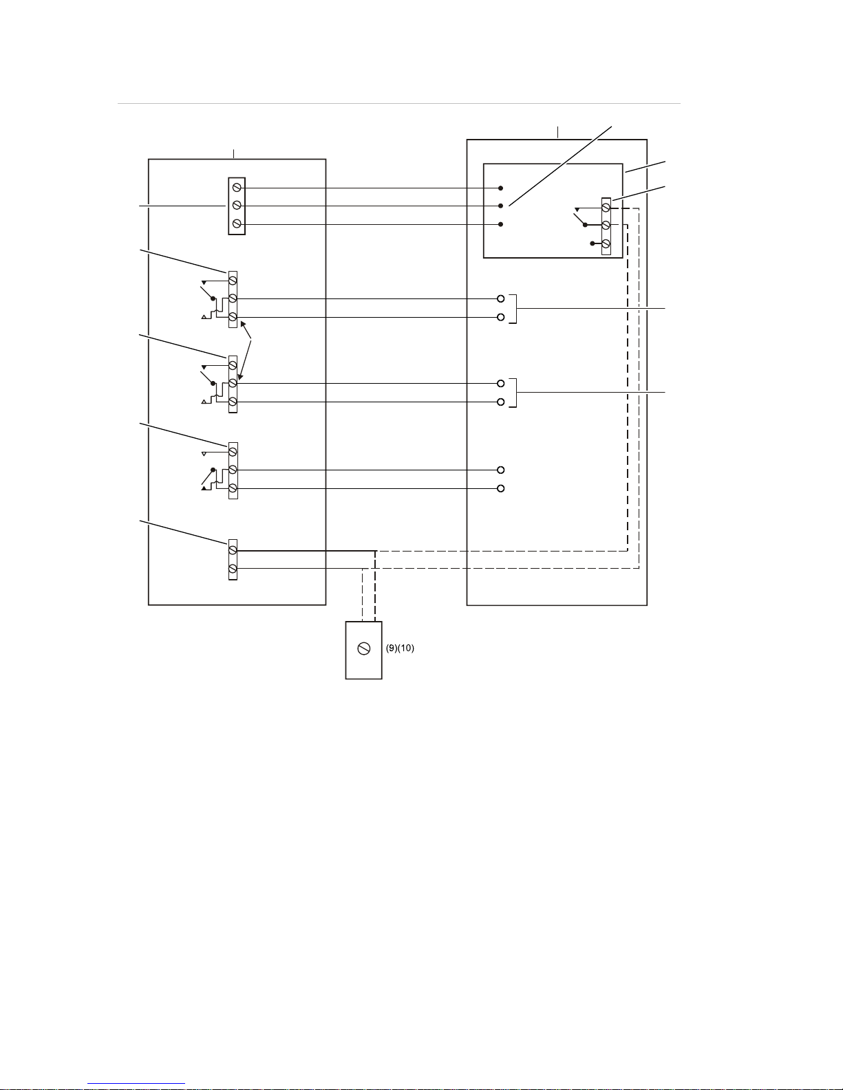
Figure 9 below shows the terminal block connections that connect the Nano
detector to other electronic components. It is recommended that all connection
wires are marked with suitable identification labels or colored rings to aid in the
connection process.
Figure 9: Electrical installation
(2
)
(3)
(1)
(4)
(1) Power supply connections
Connect to 24 VDC 1A PSU.
Do not connect 0V to EARTH.
Use screened cable with screen connected to the detector EARTH terminal.
(2) Volt-free relay contacts rated at 1A maximum at 24 VDC
All relay diagrams are shown in their contact states with the detector powered up and
operating normally.
Page 26

Chapter 2: Installation and configuration
20 LaserSense Nano Aspirating Smoke Detector Installers Handbook
The Alarm and Pre-Alarm contacts are connected as normally open and change state upon
alarm conditions.
The NO/NC (normally open/closed) terminal legends for this relay refer to the contact state in
the power‐off/fault condition, not to the “normal operation” condition. Fault relay contacts will
also change over on power‐down.
Use screened cable with screen connected to the detector EARTH terminal.
(3) Remote control input
DIP Switch 7 OFF: connect to PSU fault relay Normally Closed contacts for PSU monitoring.
Note: The INPUT terminals are set by default to monitor the power supply. If power supply
monitoring and ClassiFire Override are not required, fit a wire link across the two terminals to
prevent a fault condition on power-up.
DIP Switch 7 ON: ClassiFire Override will reduce detector sensitivity by 50% while the input
terminals are shorted together, e.g. by a key switch.
Use screened cable with screen connected to the detector EARTH terminal.
(4) External communications terminals
Optional communications card fitted (RS-485 serial communications mode):
Connect Command Module or detector RS-485 (SenseNet)
serial bus to A and B.
Set communications card address switches to identify detector.
Use screened cable. Connect screen to SCREEN terminal. Earth the screen at one end
ONLY (if using a chain of detectors connected to a Command Module, earth the cable screen
at the Command Module only).
Optional APIC card fitted (addressable communications mode):
Connect + and – IN and + and – OUT terminals to fire panel with a communications protocol
compatible with the APIC. Set APIC address switches to identify detector.
In a chain of detectors linked to a Command Module, use a serial communications card in
each detector, each set to an individual address, and communicate with the fire panel via a
single APIC in the Command Module.
Use screened cable with screen connected to the detector EARTH terminal.
WARNING: Electrocution hazard. All connections should be made with the
power turned off.
Power supply connections
The grounded power supply cable should be routed through the metal cable
gland provided, leaving about 1-
1/4
inch (35 mm) of the cable extending from
the bottom of the cable gland. Depending on the type of cable used, it may
be necessary to increase the diameter of the cable with sleeving or insulating
tape to ensure that the cable is firmly held when the cable gland is fully tightened.
Note: If this equipment is part of a fire detection system, power should be
supplied from a supervised UL Listed power supply, designed for fire system use.
To connect the power supply:
1. Remove the Nano detector front cover, and then locate the power supply
terminal block.
Page 27

Chapter 2: Installation and configuration
LaserSense Nano Aspirating Smoke Detector Installers Handbook 21
Refer to
Figure 2
on page 5 for an illustration of the Nano detector with the
front cover removed. Refer to
Figure 10
below for a detailed illustration of the
power input terminals.
2. Connect 0 V and +24 VDC to the “0V” (-24) and “+24V” screw terminals,
respectively.
3. Connect the shielded (screened) wire to the “EARTH” screw terminal.
Figure 10: Power supply terminals
Relay connections
The Nano detector includes an Alarm and a Pre-Alarm relay, which will
transfer to the normally open (N.O.) position on alarm. It also includes a
general Fault relay, which will transfer to the normally closed (N.C.) position
during a fault condition or on power-down.
The relays are of the volt-free type, with a maximum current capacity of 1A at
24 VDC maximum. To comply with radiated immunity requirements, it is
recommended that the relay connection wires be looped once around a
suppression ferrite (provided). There should be about 1-
1/4
inch (30 mm) of wire
between the end of the ferrite and the terminal block to give adequate stress relief.
To achieve this, it is necessary to strip back the cable shield approximately
5 inches (130 mm). The shield should be terminated under the cable gland cap.
The Nano detector interfaces to fire alarm panels using the detector’s
ALARM, PRE-ALARM, and FAULT relay contacts.
Make all connections shown in
Figure 11
on page 22.
Input connection
The Nano detector is fitted with an “INPUT” connection. This provides an
input which can be used to monitor the PSU or to desensitize the detector by
using the day/night feature. DIP switch number 7 must be set as described in
Figure 11
on page 22.
The INPUT terminals on the detector circuit board are set by default to monitor
the power supply. If power supply monitoring and ClassiFire override are not
required, fit a wire link across the two terminals to prevent a fault condition on
power-up.
Make all connections shown in
Figure 11
on page 22.
Page 28
Chapter 2: Installation and configuration
22 LaserSense Nano Aspirating Smoke Detector Installers Handbook
Figure 11: Wiring diagram
+24V
(16)
0V
(1)
(15)
NC
NO
C
(13)
(12)
NC
NO
C
NC
NO
C
NC
NO
C
(3)
+
–
(5)
(6)
(7)
(8)
(2)
(4)
(11)
(14)
NC = Normally closed
C = Common
NO = Normally open
(1) Detector
(2) Fire alarm control panel (FACP)
(3) Ground
(4) Power supply unit (PSU)
(5) Opens on power failure
(6) Short will indicate Alarm
(7) Short will indicate Pre-Alarm
(8) PSU fault monitoring (DIP switch 7 to OFF)
(9) Key switch
(10) Short to reduce sensitivity by 50% (DIP switch 7 set to ON)
(11) Input
(12) FAULT
(13) PRE-ALARM
(14) EOL resistor must be placed at last daisy chained detector
(15) ALARM
(16) Earth
Page 29

Chapter 2: Installation and configuration
LaserSense Nano Aspirating Smoke Detector Installers Handbook 23
Configuration
The default settings of the detector meet most application needs. These settings
can be customized to meet additional requirements. Customizing the Nano
detector requires changing the settings of the eight segments of the
configuration DIP switch (Figure 12) mounted on the main PCB. See Table 4
below and the paragraphs following the table to determine the proper switch
setting for the application.
Figure 12: Configuration DIP switch
Table 4: DIP switch settings
Setting Switch
1
Switch 2 Switch 3 Switch 4 Switch 5 Switch 6 Switch 7 Switch
8
Set detector
sensitivity
Alarm factor 6 OFF OFF
Alarm factor 7 ON OFF
Alarm factor 8 OFF ON
Alarm factor 9 ON ON
Classifire On OFF
Fixed alarms ON
Flow limit offset
±40 OFF OFF
±20 ON OFF
±5 OFF ON
±3 ON ON
Flow delay
240 seconds OFF
30 seconds ON
Input select
PSU Fault OFF
ClassiFire
Override
ON
Auto calibration
Enable OFF
Disable ON
Note: The settings in bold text are the factory default settings.
Page 30

Chapter 2: Installation and configuration
24 LaserSense Nano Aspirating Smoke Detector Installers Handbook
Alarm factor
The detector calculates sensitivity relative to the ambient pollution level. Higher
Alarm Factors provide reduced sensitivity (the alarm threshold is maintained
further away from the ambient level). Refer to the Remote Control Software
manual for further details.
Note: Changing the Alarm Factor starts a new FastLearn cycle: during the initial
15 minute learning period, the detector is incapable of reporting an alarm, and
will take 24 hours to achieve optimum performance, based on the ambient
conditions.
ClassiFire
Selecting ClassiFire On allows the artificial intelligence system to continuously
adjust alarm thresholds in order to avoid unwanted alarms from environmental
changes (recommended).
Note: Disabling this feature means that nuisance alarms due to fluctuations in
ambient pollution levels become more likely.
Fixed alarms
Switches the artificial intelligence system off, locking sensitivity to that set at
initial setup. This deactivates the dust filter monitoring system (not
recommended).
Note: Enabling this feature means that nuisance alarms due to fluctuations in
ambient pollution levels become more likely.
Flow limit offset
Flow limit offset sets the sensitivity of the airflow monitoring system. A small
offset makes the system very sensitive to air flow changes. EN 54 systems must
react to ±20% changes in airflow, which equates to a change in flow sensor
reading of +5. Areas with fluctuating air pressures may require a less sensitive
setting.
Note: Changing the flow limit offset starts a new flow calibration set up.
Flow delay
Sets the time for which a flow fault must continue before a fault is signaled.
Input select
The detector input terminal may be used to either monitor an associated power
supply for faults, or for ClassiFire override (reduces normal sensitivity by 50%).
Note: In the factory default condition, the switch is set to OFF (power supply
monitoring). This gives a fault condition if there is an open circuit on the INPUT
terminals. Fit a wire link if you do not require power supply monitoring.
Caution: If you fit a wire link across the INPUT terminals, you must set this
switch OFF, or else the detector sensitivity is dramatically and permanently
reduced by the ClassiFire override function.
Page 31

Chapter 2: Installation and configuration
LaserSense Nano Aspirating Smoke Detector Installers Handbook 25
Auto calibration
Auto calibration automatically starts a new FastLearn cycle when the detector is
powered up. This may be disabled if the previous settings need to be retained.
Final installation
Once the power and signal connections are made, place the detector cover onto
the unit and secure the cover to the unit using the cover mounting screw.
Note: The detector is designed solely for operation with the front cover securely
fitted using the cover mounting screw.
Removing the detector
Removing the detector is the reverse of the installation process, disconnecting
the pipework and wiring connections installed in the unit.
Page 32

Chapter 2: Installation and configuration
26 LaserSense Nano Aspirating Smoke Detector Installers Handbook
Page 33

LaserSense Nano Aspirating Smoke Detector Installers Handbook 27
Chapter 3
Commissioning
Summary
This chapter provides information to commission the detection system.
Content
Introduction 28
Precommissioning preparation 28
Commissioning checklist 28
Acclimation period 29
Transport time verification 29
Gross smoke test 29
Wire burner tests 30
Page 34

Chapter 3: Commissioning
28 LaserSense Nano Aspirating Smoke Detector Installers Handbook
Introduction
This chapter covers the commissioning procedures for the detector.
Commissioning strategy initially depends upon the environment in which the
detector is installed. For instance, the test for a computer room (in a relatively
clean environment) would be very different from, say, a flour mill, with a high
level of airborne particulate content.
A widely accepted standard for computer rooms or EDP areas is British Standard
BS6266, equipment overheating at a stage well before combustion. To perform
the test electrically overload a 1‑metre length of PVC insulated wire of 10/0.1mm
gauge for one minute using an appropriate power supply. The detector has two
minutes from the end of the wire burn to give an alarm indication.
For areas with higher levels of background particulate matter testing
methodology would be similar to that of standard point detectors.
Commissioning should only be done by factory-trained technicians in accordance
with applicable standards.
Precommissioning preparation
Commissioning should be performed after all construction has been completed
and cleaned of any lingering post-construction dirt. If ambient monitoring
conditions are recorded before the installation is cleaned up, they may not
accurately reflect actual normal operating conditions that need to be used as
reference data for follow-up maintenance procedures and tests.
Commissioning checklist
The following brief checklist allows quick setup of the detector. This procedure
will be adequate for most standard installations.
Caution: Ensure all wiring connections are checked prior to powering up the
detector. Incorrect wiring of the detector will cause permanent damage to the
detector.
1. Before powering up the detector, visually check all cabling to ensure correct
connection. If wire identification is not immediately clear (e.g., by use of different
colored wires or wire identification sleeves), an electrical check should be
made.
2. Disconnect the detector from the fire control unit, if applicable.
3. Power up the detector and wait for the 15 minute FastLearn cycle to finish.
The OK LED will be steadily lit when complete.
Page 35

Chapter 3: Commissioning
LaserSense Nano Aspirating Smoke Detector Installers Handbook 29
4. The detector automatically performs a FastLearn cycle which takes
approximately 15 minutes. The OK indicator on the front panel will begin to
flash. When using day/night switching, check that day start and night start
settings reflect site operations.
5. The detector will generate no alarms during the 15 minute FastLearn period
and, after this, the detector will operate at a reduced sensitivity for 24 hours
while ClassiFire learns and acclimates to the protected environment and sets up
appropriate day and night sensitivity settings.
6. Reconnect the detector to the fire control unit, if applicable
Acclimation period
The detector will operate at a reduced sensitivity for 24 hours. ClassiFire will set
up the appropriate day and night sensitivity settings. All air handling units,
thermostats, and other systems that can have an effect on the operating
environment should be turned on to simulate normal operating conditions as
closely as possible. Investigate and correct any condition that cannot be
accounted for.
Transport time verification
A maximum transport time verification test measures the amount of time it takes
for the detector to respond to smoke that enters the sampling point furthest from
the detector. The results of this test and the calculated maximum transport time
from PipeCAD must be recorded on the checklist if applicable. Measured
transport time less than the calculated time is acceptable.
For EN-54 compliance, the transport time of the last sampling hole must be
checked following installation and proven to be less than or equal to the value
determined by PipeCAD.
To measure the maximum transport time of the system:
1. Determine the furthest sampling point from the detector.
2. Allow test smoke to enter pipe at the furthest sampling point.
3. Record the amount of time for the detector to respond. This is the actual
maximum transport time. This time must not exceed 120 seconds.
Gross smoke test
The gross smoke test is a measurement of the amount of time elapsing from the
activation of the smoke generating medium, until PRE-ALARM and ALARM
states are reached. This test should be repeated at least three times with
consistent results. The recommended smoke generating medium is canned
smoke or a wire burner. Smoke from a punk or cotton wick is also acceptable.
Page 36

Chapter 3: Commissioning
30 LaserSense Nano Aspirating Smoke Detector Installers Handbook
Caution: Oil-based canisters that are used to test point detectors are not suitable
for testing aspirating systems, as the particulate is heavy and tends to drop out in
the pipe, never actually reaching the detector. Also, the oily residue that is left
behind may affect the functionality of the detector.
When using canned smoke, introduce only enough smoke into the protected area
to cause a FIRE condition. This may require a number of practice sprays. Follow
the manufacturer’s instructions.
Wire burner tests
The wire burner test is considered the most representative test of incipient fire
hazard detection in telecommunications or computer room environments. The
test is performed by applying a voltage to a piece of PVC-insulated cable. Smoke
is produced from the overheated PVC insulation by evaporation and
condensation of the plasticizer. As the wire becomes hotter, hydrogen chloride
(HCl) gas is emitted from the insulation. The by-products of overheated PVC
insulation can be detected by the Nano.
Wire burner Test 1 (optional)
The following test is considered unlikely to produce hydrochloric acid vapor. This
test may be undertaken in underfloor spaces or ceiling voids.
1. Connect a 6.5-foot (2-meter) length of wire to a 6 VAC source of at least
16 Amps rating per wire for a period of 3 minutes.
2. The system will respond within 120 seconds following de-energization. After
this period, very little smoke is given off.
Notes
• The wire is subject to cooling if positioned in direct contact with air flows and
may need to be shielded.
• The wire cross-section should be American Wire Gauge (AWG) 10 with the
following diameter and area:
Diameter = 2.59 mm or 0.10189 in.
Cross-Section Area = 5.0 mm² or 0.00775 in.²
Wire burner Test 2 (optional)
WARNING: The following test is considered to produce sufficiently high
temperature to generate small quantities of hydrogen chloride or hydrochloric
acid gas. Be sure to keep a safe distance away while voltage is being applied.
Caution: A wire burner/canned smoke test could activate spot-type detectors.
This test may be undertaken in underfloor spaces or ceiling voids where rapid
airflow may render Test 1 unsuitable.
Page 37

Chapter 3: Commissioning
LaserSense Nano Aspirating Smoke Detector Installers Handbook 31
1. Connect a 3.25-foot (1-meter) length of wire to a 6 VAC source of at least
16 Amps rating per wire for a period of 1 minute.
2. The system will respond within 120 seconds following de-energization. After
this period, most of the insulation should be burned off.
Note: The wire cross-section should be American Wire Gauge (AWG) 10 with
the following diameter and area:
Diameter = 2.59 mm or 0.10189 in.
Cross-section area = 5.0 mm² or 0.00775 in.²
Page 38

Chapter 3: Commissioning
32 LaserSense Nano Aspirating Smoke Detector Installers Handbook
Page 39

LaserSense Nano Aspirating Smoke Detector Installers Handbook 33
Chapter 4
Troubleshooting
Summary
This chapter provides information to troubleshoot the detection system.
Content
Troubleshooting the detector 34
Page 40

Chapter 4: Troubleshooting
34 LaserSense Nano Aspirating Smoke Detector Installers Handbook
Troubleshooting the detector
This chapter provides some possible solutions if a problem should occur with
your detector.
Note: Consult either the Remote Control Software User Guide or SenseNET
Software User Guide for more information about the solutions or corrective
actions discussed here.
Table 5: Troubleshooting guide
Problem Solution/Corrective Action
Nuisance alarms
occur too often
Check that the ClassiFire alarm factor setting is appropriate for the normal
working environment of the protected area.
Check that the detector is not in demo mode. This can be ascertained by
viewing the event log and checking that the entry demo mode has a higher
log entry number than the most recent FastLearn start and FastLearn end
entries. Note: Remember that the log entries are in reverse order, with the
most recent entries appearing first. If the log shows that demo mode was
invoked during the last FastLearn period, start a new FastLearn and allow
it to complete its 24-hour cycle.
From the event log, check that 24 hours have elapsed since the last
FastLearn end entry.
Check that day-night switchover times are appropriately set to reflect active
and nonactive periods.
Elevated smoke
levels do not
generate alarms
Check that detector is not isolated or in FastLearn (if Isolated, the Fault
light will be lit; if in FastLearn, the OK light will flash).
Check that the detector sampling points are in the smoke stream.
Check that sampling pipes are firmly and cleanly seated in their ports and
undamaged.
Check that the correct ClassiFire alarm setting has been set.
Check that the detector has either had a 24-hour learning period or that it
has been placed in demo mode.
Low mean output Check that the dust separator (filter) cartridge does not require changing
and that the air plenum chamber is clean. The chamber may become
clogged when, for example, heavy building activity has occurred near the
sampling pipes. If so, the chamber may require factory service. The
detector is not designed to handle large quantities of coarse debris and
dust.
Detector sensitivity
varies over time
There are many reasons why particle densities may vary, and the
ClassiFire system is designed to automatically compensate for this in order
to reduce the likelihood of nuisance alarms due to normal variations in
background smoke density. Within limits set by the ClassiFire alarm factor,
this is a normal part of the detector‘s operation.
Page 41

Chapter 4: Troubleshooting
LaserSense Nano Aspirating Smoke Detector Installers Handbook 35
Problem Solution/Corrective Action
Flow fault errors These occur when the airflow rate into the detector exceeds the
preprogrammed parameters. As the detector “learns” the flow setup from
the initial installation, this usually means that there has been some change
in conditions. A Flow High fault may indicate that a sampling pipe is
damaged, and a Flow Low fault may indicate that the pipe has been
blocked, e.g., by nearby building operations.
If the detector input is sampled from one area and the exhaust is in another
area with different pressure (e.g., the detector is in a roof space and
sampling from an enclosed room), this may lead to flow faults. In this case,
it would be necessary to lead a pipe from the exhaust to the protected area
to ensure nominal flow.
Low Flow error
message
Check that the pipe is not blocked.
If the pipe is unused, check that the flow sensor for this pipe has been
disabled.
Check that the low flow fault threshold is not set too high.
In the case of intermittent fault indications, try increasing the flow fault
delay time.
High Flow error
message
Check that the pipe is seated in the inlet and is not broken or cracked.
Check that installed pipework is fitted with endcaps. PipeCAD pipe
modeling software prompts for the use of appropriate endcaps. Open bore
pipes are not recommended.
Check that the high flow fault threshold is not set too low.
In the case of intermittent fault indications, try increasing the flow fault
delay time.
Page 42

Chapter 4: Troubleshooting
36 LaserSense Nano Aspirating Smoke Detector Installers Handbook
Page 43

LaserSense Nano Aspirating Smoke Detector Installers Handbook 37
Chapter 5
Maintenance
Summary
This chapter provides scheduled and unscheduled maintenance procedures.
Content
Introduction 38
Scheduled maintenance 38
Maintenance procedures 39
Visual check 39
Gross smoke test 39
Transport time verification test 39
Detector sensitivity test 39
Cleaning the detector 40
Replacing the dust separator cartridge 40
Page 44

Chapter 5: Maintenance
38 LaserSense Nano Aspirating Smoke Detector Installers Handbook
Introduction
This chapter contains maintenance instructions for the detector system. These
procedures should be performed on a scheduled basis. In the event that system
problems are found during routine maintenance, refer to Chapter 4
“Troubleshooting” on page 33. Failure to properly maintain the system may affect
the functioning of the system.
Scheduled maintenance
The scheduled maintenance of the system should be performed at an
established interval. The interval between performance of maintenance
procedures should not exceed any imposed regulations. (See NFPA 72 or other
local requirements.)
Local standards and specification requirements must be adhered to. A typical
maintenance plan is listed in Table 6 below.
Notes
It is prudent to disconnect or isolate the detector from the fire panel during
maintenance to prevent unintentional alarm activations.
The detector should be powered down during internal cleaning (use an air duster
can or dry air gun).
Table 6: Maintenance plan
Step Procedure
1 Check detector, wiring and pipework for damage
2 Check original design is still valid, e.g. changes due to building upgrades
3 Check detector for contamination and clean if necessary
4 Check maintenance logs for issues and rectify as appropriate
5 Check transport times against original records: significant increases or decreases in
transport times may imply damaged pipes or sampling holes that need clearing
6 Isolate detector from fire panel if required
7 Smoke test to check detector operation and Alarm relay connection
8 Simulate a fault to check the Fault relay and connection
9 Complete and file maintenance records
10 Reconnect detector to fire panel if required
Page 45

Chapter 5: Maintenance
LaserSense Nano Aspirating Smoke Detector Installers Handbook 39
Maintenance procedures
The following paragraphs outline general scheduled maintenance procedures to
be performed on an “as necessary” basis.
Visual check
The visual check must be performed every six months. This check is to ensure
pipe network integrity.
To perform the visual check, observe the entire piping network and check for
abnormalities in the pipes, including any breaks, blockages, crimps, etc.
Gross smoke test
The gross smoke test is a Go/No-Go test which ensures that the detector
responds to smoke.
This test must be performed at system commissioning and every year thereafter.
To perform this test, smoke must be introduced into the last sampling hole in
each branch of the pipe network and the proper response must be verified by the
detector. Smoke from a punk or cotton wick may be used. Aerosol test smoke
may also be used.
Note: For cleanroom applications, consult with supplier for gross smoke test
methods.
Transport time verification test
The maximum transport time of the pipe network must be measured and
compared to the recorded transport time at commissioning. (Refer to “Transport
time verification” on page 29 of this manual for test details.) The transport time
verification test must be done at commissioning and every year thereafter.
Detector sensitivity test
The detector sensitivity test must be performed within one year of installation and
every alternate year thereafter.
Example:
• Year-one check
• Year-three check
• If years one and three are OK, go to five-year interval.
The detector employs a self-monitoring, automatically-adjusting calibration for the
system. The inspection only requires a periodic visual inspection for a detector
fault indication and performing the detector sensitivity test function.
Page 46

Chapter 5: Maintenance
40 LaserSense Nano Aspirating Smoke Detector Installers Handbook
If the self-monitoring feature of the system senses that the operation of the
detector head is outside its normal range, a trouble condition will be generated.
Cleaning the detector
The exterior of the detector should be cleaned as necessary. Clean the detector
with a damp (not wet) cloth.
Caution: Do not use solvents to clean the detector. Use of solvents may cause
damage to the detector.
Replacing the dust separator cartridge
The only part that may require field replacement during servicing is the dust
separator (filter) cartridge. Its condition can be checked using the Dust Separator
test in the Diagnostics menu of the Remote Control software or SenseNET
software, which gives a percentage reading of dust separator (filter) efficiency.
When this level drops to 80%, the detector will signal a Separator Renew fault
indicating that the dust separator cartridge needs to be replaced.
For more information, refer to either the Remote Control Software User Guide or
SenseNET Software User Guide.
It is recommended that dust separators be changed at an interval of not more
than 3 years. After replacing the filter, the detector must be put into FastLearn
mode to reset the filter condition reading.
As dust contained in the dust separators may expose maintenance personnel to
a “nuisance dust” hazard as defined by the Control of Substances Hazardous to
Health (COSHH), it is strongly recommended that suitable masks and protective
clothing be worn when changing filters.
Note: Used dust separator cartridges are not intended for reuse and should be
discarded.
To replace the cartridge:
1. Remove power to the detector.
2. Remove the front cover mounting screw securing the unit’s front cover.
3. With the front cover removed, grasp the filter firmly and pull the filter out
(directly towards you).
4. Properly dispose of the used cartridge.
5. Locate the orientation markings on the new filter cartridge. The word “IN” is
marked on one side and the other is marked “OUT”.
6. Insert the replacement filter cartridge so that the “IN” mark on the cartridge is
on the left as viewed in Figure 13 on page 41.
7. Slide the cartridge all the way into place.
Page 47

Chapter 5: Maintenance
LaserSense Nano Aspirating Smoke Detector Installers Handbook 41
8. Replace the detector cover and secure it into place.
9. Initiate a FastLearn routine by reenergizing the detector.
Figure 13: Location of dust separator cartridge
(1) Dust separator (filter) cartridge
Page 48

Chapter 5: Maintenance
42 LaserSense Nano Aspirating Smoke Detector Installers Handbook
Page 49

LaserSense Nano Aspirating Smoke Detector Installers Handbook 43
Appendix A
Communications card and
APIC
Summary
This appendix provides information about the communication card and the APIC.
Content
Optional communications card 44
Setting the detector address 45
Optional APIC 47
Page 50

Appendix A: Communications card and APIC
44 LaserSense Nano Aspirating Smoke Detector Installers Handbook
Optional communications card
An optional communications card can be fitted inside the Nano detector to
provide an RS-232 serial port and RS-485 network communication.
Figure 14: Optional communications card
(1) Card locating post
(2) Ribbon cable connection on detector main PCB
(3) Detector address DIP switch
(4) M3 x 6 fixing screw (provided with the card)
(5) *Support spacer, nylon (provided with the card)
(6) RS-232 serial port: Use 9-pin D-type null modem cable to connect to a PC.
* If the communication card is not factory installed, you must install the adhesive back support
spacer onto the detector housing. A recess is provided in the housing to ensure proper
placement of the support spacer.
Direct connection of a PC to the communications card is done using a 9-pin
RS-232 interface on the communications card, using a null modem cable
configuration, as shown in Figure 15 on page 45.
Page 51

Appendix A: Communications card and APIC
LaserSense Nano Aspirating Smoke Detector Installers Handbook 45
Figure 15: RS-232 cable connections
(1) 9-pin female “D” connector
(2) 9-pin female “D” connector
A connected PC can access the detector event memory to review previous or
current events, such as detector alarms or faults. The detector internal chart
recorder can also be accessed to allow analysis of detector behaviour (refer to
the Remote Control User Manual for further information). The PC cannot be used
to configure the detector except to enter time and date settings for the detector
event log and chart recorder to be viewed in the remote control software. The
detector does not incorporate a real-time clock, so the time and date need to be
re-entered if the detector is powered down for any reason.
Installation of the communications card also provides the detector with RS-485
network communication via the A, B, and SCREEN terminals on the detector
main board (Figure 9 on page 19). This can be used for simple remote display
indication or integration into a larger site wide management and display system,
separate from the local fire detection and alarm system.
Setting the detector address
In order to identify itself to the command module or fire panel, each detector
needs to have a unique address ranging from 1 to 127. The detector address is
set using the DIP switch located at the optional communication board. The switch
settings are up for 1 and down for 0, and the detector address is set as a 7-bit
binary code (switch 8 equates to a value of 128 and so is outside the usable
address range).
Figure 16 shows an example where the address equates to “01100011” in binary,
or:
(1 x 1) + (1 x 2) + (0 x 4) + (0 x 8) + (0x 16) + (1 x 32) + (1 x 64) + (0 x 128) = 99
Page 52

Appendix A: Communications card and APIC
46 LaserSense Nano Aspirating Smoke Detector Installers Handbook
Figure 16: Sample DIP switch settings
The full range of available addresses and their relevant switch settings are
provided in Table 7 for reference.
Note: Addresses chosen for detectors do not have to be consecutive or in a
given order as long as they are all different.
Table 7: Address table
Address
1 2 3 4 5 6 7 8 65 1 0 0 0 0 0 1 0
1 1 0 0 0 0 0 0 0 66 0 1 0 0 0 0 1 0
2 0 1 0 0 0 0 0 0 67 1 1 0 0 0 0 1 0
3 1 1 0 0 0 0 0 0 68 0 0 1 0 0 0 1 0
4 0 0 1 0 0 0 0 0 69 1 0 1 0 0 0 1 0
5 1 0 1 0 0 0 0 0 70 0 1 1 0 0 0 1 0
6 0 1 1 0 0 0 0 0 71 1 1 1 0 0 0 1 0
7 1 1 1 0 0 0 0 0 72 0 0 0 1 0 0 1 0
8 0 0 0 1 0 0 0 0 73 1 0 0 1 0 0 1 0
9 1 0 0 1 0 0 0 0 74 0 1 0 1 0 0 1 0
10 0 1 0 1 0 0 0 0 75 1 1 0 1 0 0 1 0
11 1 1 0 1 0 0 0 0 76 0 0 1 1 0 0 1 0
12 0 0 1 1 0 0 0 0 77 1 0 1 1 0 0 1 0
13 1 0 1 1 0 0 0 0 78 0 1 1 1 0 0 1 0
14 0 1 1 1 0 0 0 0 79 1 1 1 1 0 0 1 0
15 1 1 1 1 0 0 0 0 80 0 0 0 0 1 0 1 0
16 0 0 0 0 1 0 0 0 81 1 0 0 0 1 0 1 0
17 1 0 0 0 1 0 0 0 82 0 1 0 0 1 0 1 0
18 0 1 0 0 1 0 0 0 83 1 1 0 0 1 0 1 0
19 1 1 0 0 1 0 0 0 84 0 0 1 0 1 0 1 0
20 0 0 1 0 1 0 0 0 85 1 0 1 0 1 0 1 0
21 1 0 1 0 1 0 0 0 86 0 1 1 0 1 0 1 0
22 0 1 1 0 1 0 0 0 87 1 1 1 0 1 0 1 0
23 1 1 1 0 1 0 0 0 88 0 0 0 1 1 0 1 0
24 0 0 0 1 1 0 0 0 89 1 0 0 1 1 0 1 0
25 1 0 0 1 1 0 0 0 90 0 1 0 1 1 0 1 0
26 0 1 0 1 1 0 0 0 91 1 1 0 1 1 0 1 0
27 1 1 0 1 1 0 0 0 92 0 0 1 1 1 0 1 0
28 0 0 1 1 1 0 0 0 93 1 0 1 1 1 0 1 0
29 1 0 1 1 1 0 0 0 94 0 1 1 1 1 0 1 0
30 0 1 1 1 1 0 0 0 95 1 1 1 1 1 0 1 0
31 1 1 1 1 1 0 0 0 96 0 0 0 0 0 1 1 0
32 0 0 0 0 0 1 0 0 97 1 0 0 0 0 1 1 0
33 1 0 0 0 0 1 0 0 98 0 1 0 0 0 1 1 0
34 0 1 0 0 0 1 0 0 99 1 1 0 0 0 1 1 0
35 1 1 0 0 0 1 0 0 100 0 0 1 0 0 1 1 0
36 0 0 1 0 0 1 0 0 101 1 0 1 0 0 1 1 0
37 1 0 1 0 0 1 0 0 102 0 1 1 0 0 1 1 0
Page 53

Appendix A: Communications card and APIC
LaserSense Nano Aspirating Smoke Detector Installers Handbook 47
38 0 1 1 0 0 1 0 0 103 1 1 1 0 0 1 1 0
39 1 1 1 0 0 1 0 0 104 0 0 0 1 0 1 1 0
40 0 0 0 1 0 1 0 0 105 1 0 0 1 0 1 1 0
41 1 0 0 1 0 1 0 0 106 0 1 0 1 0 1 1 0
42 0 1 0 1 0 1 0 0 107 1 1 0 1 0 1 1 0
43 1 1 0 1 0 1 0 0 108 0 0 1 1 0 1 1 0
44 0 0 1 1 0 1 0 0 109 1 0 1 1 0 1 1 0
45 1 0 1 1 0 1 0 0 110 0 1 1 1 0 1 1 0
46 0 1 1 1 0 1 0 0 111 1 1 1 1 0 1 1 0
47 1 1 1 1 0 1 0 0 112 0 0 0 0 1 1 1 0
48 0 0 0 0 1 1 0 0 113 1 0 0 0 1 1 1 0
49 1 0 0 0 1 1 0 0 114 0 1 0 0 1 1 1 0
50 0 1 0 0 1 1 0 0 115 1 1 0 0 1 1 1 0
51 1 1 0 0 1 1 0 0 116 0 0 1 0 1 1 1 0
52 0 0 1 0 1 1 0 0 117 1 0 1 0 1 1 1 0
53 1 0 1 0 1 1 0 0 118 0 1 1 0 1 1 1 0
54 0 1 1 0 1 1 0 0 119 1 1 1 0 1 1 1 0
55 1 1 1 0 1 1 0 0 120 0 0 0 1 1 1 1 0
56 0 0 0 1 1 1 0 0 121 1 0 0 1 1 1 1 0
57 1 0 0 1 1 1 0 0 122 0 1 0 1 1 1 1 0
58 0 1 0 1 1 1 0 0 123 1 1 0 1 1 1 1 0
59 1 1 0 1 1 1 0 0 124 0 0 1 1 1 1 1 0
60 0 0 1 1 1 1 0 0 125 1 0 1 1 1 1 1 0
61 1 0 1 1 1 1 0 0 126 0 1 1 1 1 1 1 0
62 0 1 1 1 1 1 0 0 127 1 1 1 1 1 1 1 0
63 1 1 1 1 1 1 0 0
64 0 0 0 0 0 0 1 0
Optional APIC
When a command module is being used to manage one or more detectors (the
maximum limit is 127) an addressable protocol interface card (APIC) is required
to decode detector status information in the command module and convey to the
Fire Panel via the Addressable Bus 1 and Bus 2 terminal block connections (see
“Electrical installation” on page 19 for details). In this configuration only one
interface is required and all detector information is available through this
interface, one address per device.
Note: Either an optional communication card or an APIC can be installed in the
detector, not both. They are mounted the same and use the same connection on
the detector main PCB.
APICs plug into the main PCB via a ribbon cable (see Figure 14 on page 44).
Once plugged in, the addressable signaling line circuit (SLC) in and out are
connected to the main PCB addressable bus terminals and the address DIP
switches are set to the SLC address. Refer to the APIC installation sheet for
details.
Page 54

Appendix A: Communications card and APIC
48 LaserSense Nano Aspirating Smoke Detector Installers Handbook
Note: Some addressable protocols may limit the maximum number of device
addresses to less than 127. Some protocols may not support all of the available
alarm levels, and fault reporting is usually a general fault with no detailed fault
information.
Page 55

LaserSense Nano Aspirating Smoke Detector Installers Handbook 49
Glossary
°C Degrees centigrade
°F Degrees Fahrenheit
A Ampere
AC Alternating current
ADA Americans with Disabilities Act
AH Ampere hour
AHJ Authority having jurisdiction
ARC Automatic release circuit
AWG American wire gauge
APIC Addressable protocol interface card
CSFM California State Fire Marshal
DACT Digital alarm comm. transmitter
DC Direct current
DET Detector
EOLD End of line device
EOLR End of line resistor
FM Factory Mutual
FSD Full scale deflection
ft. Feet
HSSD High sensitivity smoke detector
Hz Hertz (frequency)
in. Inches
LCD Liquid crystal display
LED Light emitting diode
MEA Materials and Equipment Acceptance
Division of the City of New York
NAC Notification appliance circuit
N.C. Normally closed
NEC National Electrical Code
NFPA National Fire Protection Association
N.O. Normally open
Page 56

Glossary
50 LaserSense Nano Aspirating Smoke Detector Installers Handbook
NYC New York City
PCB Printed circuit board
pF Pico farads
P/N Part number
PSU Power supply unit
RAM Random access memory
SLC Signaling line circuit
TB Terminal block
UL/ULI Underwriters Laboratories, Inc.
V Volts
VAC Volts AC
VDC Volts DC
VRMS Volts root mean square
Page 57

LaserSense Nano Aspirating Smoke Detector Installers Handbook 51
Index
A
Advisory messages, iii
Alarm Factor, 24
Antistatic precautions, 8
APIC, 47
Auto calibration, 25
C
ClassiFire
, 17, 21, 23, 24, 29
Commissioning, 28
Acclimation period, 29
Transport time verification, 29
Communications card, 44
Configuration, 23
Configuration DIP switch settings, 23
D
Detector
internal components, 5
Detector address
Setting the detector address, 45
E
EN 54-20 compliance, iv
F
FastLearn, 25, 28, 41
Fixed alarms, 24
Flow delay, 24
I
Indicators, 4
Input connection, 21
Input select, 24
Installation, 16
Electrical installation, 19
Installation guidelines, 16
Mechanical installation, 17
M
Maintenance, 39
Replacing the dust separator (filter), 40
P
Power supply connections, 20
R
Relay connections, 21
Removing the detector, 25
S
Software
Available software, 2
Specifications, 3
System design, 9
Air handling unit installation, 10
Below or above the ceiling installation, 11
Return air duct sampling method, 13
Return air grill sampling method, 15
Sample pipe networks, 10
T
Testing
Gross smoke test, 29
Troubleshooting, 34
W
Wire burner tests, 30
Wiring diagram, 22
Page 58

Index
52 LaserSense Nano Aspirating Smoke Detector Installers Handbook
 Loading...