


Undersink
REVERSE OSMOSIS
DRINKING WATER SYSTEM
ERO-375
HERO-375
Safety Guides
Installation
Operation
Maintenance
Repair Parts
EcoWater Systems LLC
P.O. Box 64420
St. Paul, MN 55164
TEL (651) 739-5330
System tested and certified by NSF International against NSF/ANSI Standard 58.
See performance data sheet for details.
7300493 (Rev. D 9/17/08)

TABLE OF CONTENTS
Warranty Information . . . . . . . . . . . . . . . . . . . . . . . . . . . . 2 Safety Guides . . . . . . . . . . . . . . . . . . . . . . . . . . . . . . . . . . . 3 Specifications . . . . . . . . . . . . . . . . . . . . . . . . . . . . . . . . . . . 4 What the Drinking Water System Will Do. . . . . . . . . . . 5 Components of the System. . . . . . . . . . . . . . . . . . . . . . . . 5 Checks to Make Before Installing . . . . . . . . . . . . . . . . . . 5 Installing. . . . . . . . . . . . . . . . . . . . . . . . . . . . . . . . . . . . . 6-14
Feed Water Supply . . . . . . . . . . . . . . . . . . . . . . . . . . . . . 6 Reject Water Drain Fitting . . . . . . . . . . . . . . . . . . . . . . . 6 Installing Faucet . . . . . . . . . . . . . . . . . . . . . . . . . . . . . . . 7 Installing RO Assembly & Storage Tank. . . . . . . . . . . 8 Tubing Connections . . . . . . . . . . . . . . . . . . . . . . . . . . . . 9 Connect Water Supply, Storage Tank
& Drain Tubing . . . . . . . . . . . . . . . . . . . . . . . . . . . . . . . 10 Sanitizing / Pressure Testing / Purging . . . . . . . . . . . 11 Installing Hydrolink™ RO Module . . . . . . . . . . . . . . 12
Installing (or Replacing) Batteries . . . . . . . . . . . . . . . 12 Connecting Hydrolink™ RO Module to Remote . . 13 How the Hydrolink™ RO Module Works . . . . . . . . . . 14 Status Screen on the Remote . . . . . . . . . . . . . . . . . . . . . 14 Status LED on the Hydrolink™ RO Module. . . . . . . . 15 Checking RF Signal Strength . . . . . . . . . . . . . . . . . . . . . 15 Changing the Remote Display . . . . . . . . . . . . . . . . . 16-17 How the RO System Works . . . . . . . . . . . . . . . . . . . . . . 18 Replacing the Filters & RO Membrane. . . . . . . . . . . . . 19 Care of Your Reverse Osmosis System . . . . . . . . . . 19-22 Troubleshooting . . . . . . . . . . . . . . . . . . . . . . . . . . . . . . . . 22 System Schematic. . . . . . . . . . . . . . . . . . . . . . . . . . . . . . . 23 Installation of Optional Fittings. . . . . . . . . . . . . . . . . . . 24 Remote Installation . . . . . . . . . . . . . . . . . . . . . . . . . . . . . 25 Repair Parts . . . . . . . . . . . . . . . . . . . . . . . . . . . . . . . . . 26-27
WARRANTY INFORMATION
LIMITED WARRANTY
1, 3, 5 and 10 YEAR
EcoWater Systems LLC, guarantees to the original owner that:for a period of ten (10) years from from the date of purchase, the RO holding tank will be free from defects in material and workmanship. All other parts of the drinking water system will be guaranteed for a period of five (5) years from defects in material and workmanship. The electronic faucet will be guaranteed for three (3) years from defects in material and workmanship. The reverse osmosis membrane will be guaranteed for one (1) year from defects in material and workmanship. The prefilters and postfilter, which are expendable, are not covered under this warranty. This warranty does not include normal shipping, installation or service charges.
Any defective part, as described above, which fails within the ten, five, three or one year period from date of purchase will be repaired or replaced, F.O.B. our plant, St. Paul, MN.
The sole obligation of EcoWater Systems LLC, under these guarantees, is to replace or repair the component or part which proves to be defective, within the specified time period, and EcoWater is not liable for consequential or incidental damages due to misuse, alteration, neglect, freezing or a force of nature. All implied warranties, including any implied warranty of merchantability or of fitness for a particular purpose, are disclaimed to the extent they extend beyond the above periods. No dealer, agent, representative, or other person is authorized to extend or expand these guarantees.
Some states do not allow limitations on how long an implied warranty lasts or exclusions or limitations of incidental or consequential damage, so the limitations and exclusions in this warranty may not apply to you. This warranty gives you specific legal rights, and you may have other rights which vary from state to state.
2

SAFETY GUIDES
Read all steps, guides and rules carefully before installing and using the Drinking Water System. Follow all steps exactly to correctly install.
BE SURE TO FOLLOW APPLICABLE STATE AND LOCAL PLUMBING AND SANITATION CODES when installing the Drinking Water System. Massachusetts plumbing code 248 CMR shall be adhered to. Please consult your licensed plumber. Using a qualified installer is recommended.
The Drinking Water System works on water pressures of 40 psi minimum, to 100 psi maximum (see the table on Page 4). If house water pressure is over the maximum, install a pressure reducing valve in the water supply line to the Drinking Water System.
This system is acceptable for treatment of influent concentrations of no more than 27 mg/L nitrate and 3 mg/L nitrite measured as N and is certified for nitrate/nitrite reduction only for water supplies with a pressure of 280 kPa (40 psig) or greater. This system is supplied with a nitrate/nitrite test kit. Product water should be monitored periodically according to the instructions provided with the test kit.
DO NOT install the Drinking Water System outside, or in extreme hot or cold temperatures. Temperature of the water supply to the Drinking Water System must be between 40°F (minimum) and 100°F (maximum), see the table on Page 4. DO NOT INSTALL ON HOT WATER.
Read the other limits (pH, water hardness, etc.), Page 4, and be sure the water supply conforms.
Do not use with water that is microbiologically unsafe or of unknown quality without adequate disinfection before or after the system. Systems certified for cyst reduction may be used on disinfected water that may contain filterable cysts.
This system shall only be used for arsenic reduction on chlorinated water supplies containing detectable residual free chlorine at the system inlet. Water systems using an inline chlorinator should provide a one minute chlorine contact time before the RO system. Conforms to NSF/ANSI 58 for pentavalent arsenic reduction. See performance data sheet and Arsenic Facts section for an explanation of reduction performance.
NOTE: This equipment has been tested and found to comply with the limits for a Class B digital device, pursuant to Part 15 of the FCC Rules. These limits are designed to provide reasonable protection against harmful interference in a residential installation. This equipment generates, uses, and can radiate radio frequency energy and, if not installed and used in accordance with the instructions may cause harmful interference to radio communications. However, there is no guarantee that interference will not occur in a particular installation. If this equipment does cause harmful interference to radio or television reception, which can be determined by turning the equipment off and on, the user is encouraged to try to correct the interference by one or more of the following measures:
Reorient or relocate the receiving antenna.
Increase the separation between the equipment and receiver.
Connect the equipment into an outlet on a circuit different from that to which the receiver is connected.
Consult the dealer or an experienced radio/TV technician for help.
Changes or modifications not expressly approved by EcoWater Systems could void the user’s authority to operate the equipment.
This device complies with Industry Canada Standard RSS210. Operation is subject to the following two conditions: (1) this device may not cause interference, and (2) this device must accept any interference, including interference that may cause undesired operation of the device.
Ce dispositif est conforme avec la norme CNR-210 d’Industrie Canada. Le fonctionnement du dispositif est sujet aux deux conditions suivantes: (1) le dispositif ne doit pas causer de brouillage, et (2) le dispositif doit accepter tous brouillages, incluant tous brouillages qui peut nuire au bon fonctionnement du dispositif.
European Directive 2002/96/EC requires all electrical and electronic equipment to be disposed of
according to Waste Electrical and Electronic Equipment (WEEE) requirements. This directive or similar laws are in place nationally and can vary from region to region. Please refer to your state and local laws for proper disposal of the equipment.
3

SPECIFICATIONS
Feed water pressure limits - pounds per square inch (psi). . . . . . . . . . . . . . . . . . . . . . . . . . . . . . . . . . . . 40 - 100 Feed water temperature limits - minimum / maximum degrees F . . . . . . . . . . . . . . . . . . . . . . . . . . . . . 40 - 100 Maximum total dissolved solids (TDS) - parts per million (ppm) . . . . . . . . . . . . . . . . . . . . . . . . . . . . . . . . 2000 Maximum water hardness @ 6.9 pH - grains per gallon (gpg) . . . . . . . . . . . . . . . . . . . . . . . . . . . . . . . . . . . . . 10 Maximum iron, manganese, hydrogen sulfide. . . . . . . . . . . . . . . . . . . . . . . . . . . . . . . . . . . . . . . . . . . . . . . . . . . . 0 Chlorine in water supply . . . . . . . . . . . . . . . . . . . . . . . . . . . . . . . . . . . . . . . . . . . . . . . . . . . . . . . . . . . . allowable Feed water pH limits (pH) . . . . . . . . . . . . . . . . . . . . . . . . . . . . . . . . . . . . . . . . . . . . . . . . . . . . . . . . . . . . . . . . . 4 - 11 Product (quality) water, 24 hours - gallons (closed system). . . . . . . . . . . . . . . . . . . . . . . . . . . . . . . . . . . . 17.4 Percent rejection of TDS, minimum (new membrane) . . . . . . . . . . . . . . . . . . . . . . . . . . . . . . . . . . . . . . . . . . 95 Automatic shutoff control . . . . . . . . . . . . . . . . . . . . . . . . . . . . . . . . . . . . . . . . . . . . . . . . . . . . . . . . . . . . . . . . . . . yes Efficiency . . . . . . . . . . . . . . . . . . . . . . . . . . . . . . . . . . . . . . . . . . . . . . . . . . . . . . . . . . . . . . . . . . . . . . . . . . . . . . 10.14 Recovery . . . . . . . . . . . . . . . . . . . . . . . . . . . . . . . . . . . . . . . . . . . . . . . . . . . . . . . . . . . . . . . . . . . . . . . . . . . . . . 18.98
Chlorine reduction (max. of 2.0 ppm) by the RO Prefilter. REGULAR MAINTENANCE REQUIRED. Chlorine will destroy the RO membrane, See Page 5.
Feed water supply at 50 psi, 77°F, and 750 TDS - Quality water production and percent rejection all vary with changes in pressure, temperature and total dissolved solids.
Efficiency rating means the percentage of the influent water to the system that is available to the user as revers osmosis treated water under operating conditions that approximate typical daily use.
Recovery rating means the percentage of the influent water to the membrane portion of the system that is available to the user as reverse osmosis treated water when the system is operated without a storage tank or when the storage tank is bypassed.
This system conforms to NSF/ANSI 58 for the specific performance claims as verified and substantiated by test data.
11” |
|
|
|
|
|
12-1/2” |
|
|
|
|
|
|
|
3-1/2” |
|
|
|
|
|
|
|
|
|
|
|
|
|||
|
|
|
|
|
|
|||||||||
|
|
|
|
|
|
|
|
|
|
|
||||
|
|
|
|
|
|
|
|
|
|
|
|
|
|
|
|
|
|
|
|
|
|
|
|
|
|
|
|
|
|
|
|
|
|
|
|
|
|
|
|
|
|
|
|
|
|
|
|
|
|
|
|
|
|
|
|
|
|
|
|
|
|
|
|
|
|
|
|
|
|
|
|
|
|
|
|
|
|
|
|
|
|
|
|
|
|
|
|
|
|
17”
16”
PRETREATMENT OF THE WATER SUPPLY NEED-
ED TO PREVENT SCALING
TO USE THE CHART...
...Locate the intersecting point of feed water hardness and pH.
If this point falls within the shaded area, pretreatment* is needed.
*Softening of the water is the suggested pretreatment.
4
WHAT THE DRINKING WATER SYSTEM WILL DO
The drinking water system is a REVERSE OSMOSIS (RO) water treating unit. Reverse osmosis is a way of reducing dissolved solids and organic matter from water by passing it through a special membrane. The membrane separates minerals and impurities from the water, and they are flushed to the drain. Good tasting, high quality product water goes directly to the drinking water faucet, or to the storage area. The system makes a good supply of drinking water each day (see specifications). How much it will make depends on the feed water supply pressure, temperature, and quality.
Pre and postfilters are replaceable cartridges. The carbon prefilter reduces some chlorine (see specifications) while also filtering sediments. The postfilter reduces any other undesirable tastes and odors before you use the water.
The RO system also includes a standard faucet assembly to vend the drinking water, and a storage tank.
NOTE: A performance data sheet is included listing what the system will reduce from the water supply. See performance data sheet for individual contaminants and reduction performance.
The drinking water system fits under the kitchen or bathroom sink. However, you can install it where most convenient. You do need a COLD water supply pipe and drain point within a few feet (6' tubing lengths included). You can buy longer lengths of tubing if needed to reach more distant points. Be sure tubing is acceptable for use on potable water supplies.
COMPONENTS OF THE SYSTEM
The RO system is shipped in one carton, consisting of:
(1)Storage Tank,
(2)Faucet,
(3)RO Assembly, with color coded tubing lengths attached,
(4)Parts bag containing storage tank shutoff valve, drain flow restrictor, mounting washers and screws.
(5)Separate 30" length of 3/8" tubing.
(6)Hydrolink™ RO Module, with batteries and cable, in its own box (Model HERO-375 only).
INSTALLER PROVIDES: (1) fittings to tap the cold water pipe for a feed water source to the RO . . . must adapt to 1/4" tubing; and (2) a drain point for RO discharge water .
. . must adapt to 3/8" OD tubing. Both items must comply with state and /or local codes. Optional fittings are available from EcoWater for use in areas where codes permit.
THINGS TO CHECK BEFORE YOU START TO INSTALL:
FEED WATER - The water supply to the Drinking Water System must have the qualities listed in the specifications. If not, it will not make product water as it should and life of the RO membrane is shortened. City water most often will have these qualities. Well water may need conditioning. Have the water tested by a water analysis laboratory, and get their recommendations for treatment. Observe plumbing codes when providing a water supply to the RO. A self-piercing saddle valve is available for tapping into a cold water pipe (check local plumbing codes). Refer to Pages 24 and 27.
NOTE: Codes in the state of Massachusetts require installation by a licensed plumber, and do not permit the use of the drain clamp. For installation, use plumbing code 248CMR of the Commonwealth of Massachusetts.
CAUTIONS:
Feed water must have chlorine reduced (prefilters reduce up to amount shown in specifications, Page 4). Chlorine will destroy the RO membrane cartridge. Be sure to service the prefilters, Page 19.
DRAIN POINT - A suitable drain point (check your local plumbing codes) is needed for reject water from the RO membrane cartridge. Running the RO drain tubing directly to a floor drain, laundry tub, sump, standpipe, etc., is preferred. If that is not possible or practical, using the sink p-trap drain pipe is suggested. A drain clamp (drilling required), or a special drain adapter are available from EcoWater to use where codes permit. Refer to Pages 24 and 27. These options install on the sink drain pipe tailpiece, above the p-trap.
RO FAUCET - The RO product water faucet installs on the sink, or on the countertop next to the sink. Often, it's installed in an existing sink spray attachment hole. Space is required underneath for tubing to and from the faucet, and for securing it in place. Refer to Pages 7 and 10.
MOUNTING SURFACE - The RO assembly mounts on a wall surface under the sink, or you can lay it on the bottom of the cabinet. Special washers and screws are included for wall mounting.When the storage tank is full of water, it weighs about 30 pounds. Be sure to set on a surface that will support this weight.
5

INSTALLATION - FEED WATER SUPPLY
Check and comply with local plumbing codes as you |
FIGURE 1 |
|
plan, then install a cold feed (supply) water fitting. The |
||
|
||
fitting must provide a leak tight connection to the RO |
|
|
1/4" OD tubing, see Figure 6, Page 10. A typical installa- |
|
|
tion, using standard plumbing fittings is shown in |
|
|
Figure 1. A saddle valve (part no. 7011272) is available |
|
|
to use where codes permit. Installation instructions are |
|
|
on Page 24. |
|
|
NOTE: Codes in the state of Massachusetts require |
|
|
installation by a licensed plumber, and do not permit |
|
|
the use of the drain clamp. For installation, use plumb- |
|
|
ing code 248-CMR of the Commonwealth of |
|
|
Massachusetts. |
|
|
PIPE FITTINGS (compression shown) |
|
|
IMPORTANT: Before starting, close the hot and cold |
|
|
water shutoff valves (See Figure 1). Use a pan to catch |
|
|
water when disassembling the pipe. |
|
|
Complying with plumbing codes, install a fitting on the |
|
|
kitchen cold water pipe to adapt 1/4" OD tubing. A typ- |
|
|
ical connection is shown in Figure 1. You can use solder |
|
|
or threaded fittings. If threaded fittings are used, be |
|
|
sure to use pipe joint compound or Teflon tape on out- |
|
|
side threads. |
|
|
Do not connect the tubing to the fitting until Step 2, top |
|
|
of Page 10. |
|
REJECT WATER DRAIN FITTING
Running the RO drain tubing directly to a floor drain,
FIGURE 2
laundry tub, sump, standpipe, etc., is preferred. If that is not possible or practical, check and comply with local plumbing codes as you plan, then install a drain fitting for RO reject water. This fitting is usually installed at the sink p-trap (always above). It must provide a leak-tight connection to 3/8" OD tubing from the RO product water faucet airgap, see Figure 6, Page 10. Typical drain fitting installations are listed below. A drain adapter (part no. 7192230) is available to use where codes permit. Installation instructions are on Page 24. Other options are shown on Page 27.
“Y” BRANCH TAIL PIECE, OR OTHER APPROVED P-TRAP DRAIN
Reject water from the RO is routed to the RO faucet airgap (1/4" tubing), then to the drain point with 3/8" OD tubing. COMPLYING WITH PLUMBING CODES, install a fitting to accept the 3/8" tubing. Figure 2 shows typical p-trap and "Y" branch tail piece type drains.
Do not connect drain tubing until Step 1, top of Page 10.
6
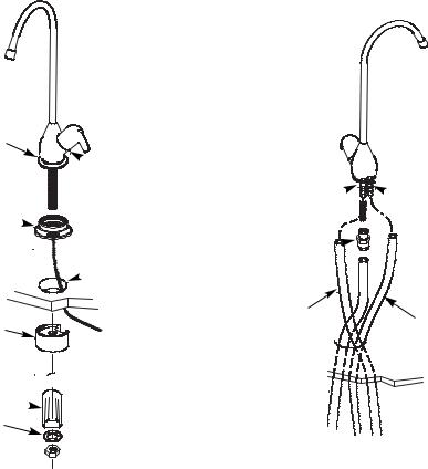
INSTALL THE FAUCET
Select one of the following places to install the faucet. Be sure there's room underneath so you can make the needed connections.
In an existing sink spray attachment hole.
Drill a hole in the sink top.
Drill a hole in the countertop, next to the sink.
NOTE: Looking at Figure 3, be sure the faucet base will fit flat against the surface at the selected location so the o-ring will seal.
1.Do not connect drain tubing until Step 1, top of Page 10.
2.For Model ERO-375, slide the chrome washer onto the faucet stud, Figure 3.
3.For Model HERO-375, snap the o-ring in the groove on the bottom of the ring and slide the monitor ring onto the faucet stud. The monitor ring LED wire must be routed through the sink or countertop hole and through the spacer, if used, Figure 3.
NOTE: If you will route the RO drain tubing directly to the drain point, disregard Steps 4 and 6 and do Step 1 on top of Page 10.
4. Take the 30" length of 3/8" black tubing and push one end onto the 3/8" faucet barb fitting, Figure 4.
5.Move the RO system into position, under the sink. (Referring to Page 8, hang the system on cabinet wall, or lay on the floor surface, as desired.)
6.Route the 1/4" red tubing from the bottom, up through the faucet mounting hole. Push the end of the tubing onto the 1/4" barb fitting.
7.Work tubing and the faucet stud down, into the mounting hole.
8.On the underside of the sink or countertop, install the spacer (Model HERO-375 only), plastic bushing, flat washer, and hex nut. Slide the large steel washer in place, between the bushing (or spacer) and the bottom of the sink or countertop. Then, tighten the hex nut securely. Make sure that the LED wire is in a position so that it will not be cut, pinched or kinked before tightening the faucet assembly.
9.Thread the tubing connector onto the bottom of the faucet stud.
10.Push the end of the 3/8" blue tubing from the RO, into the tubing connector installed in Step 9.
NOTE: See tubing connection procedures on Page 9. For ease of service and maintenance, keep tubing lengths long enough so removal of the RO system from under the sink is possible.
FIGURE 3 - FAUCET INSTALLATION |
FIGURE 4 - TUBING CONNECTIONS |
Model ERO-375 only |
spout |
|
|
Model HERO-375 only |
|
washer |
|
electronics ring 
o-ring 

spacer
steel washer
(large)
 bushing

 washer
hex nut
lever
 faucet
 1-1/4” dia. hole
wire will be connected to Hydrolink™ RO Module in manifold
3/8” barb fitting
tubing connector 1/4” to 3/8”
3/8” black tubing, 30” long
3/8” blue tubing from RO
 1/4” barb fitting
1/4” red tubing from RO
7

INSTALL RO ASSEMBLY AND STORAGE TANK
1.Hold the RO assembly up to the wall surface where you will install it. Mark locations for the hanger washers and screws.
2.Fasten the hanger washers to the wall surface. Wood screws are included for fastening to a wood surface. Provide other screws for other surfaces as needed.
3.Hang the RO assembly on the hanger washers.
4.Move the storage tank into place, setting on the floor surface. Use the stand, included with the tank, and position the tank upright, or on its side.
5.Apply teflon tape on the tank nipple threads and install the shutoff valve.
FIGURE 5
connector (shut
off) valve
storage tank
NOTE: Be sure to allow a minimum space of 4" above the system for removing the top cover to change batteries (on HERO-375).
9”
hanger washer (2)
screw (2)
NOTE: Be sure to allow a minimum space of 1-1/2" under the system for removing the cartridges in order to change them.
8

TUBING CONNECTIONS
HOW TO CUT AND CONNECT THE TUBES
Your Reverse Osmosis Water System includes push-in fittings for quick tubing connection. Review the following instructions before connecting the tubes in the next step.
Cut tubes to length
1.Use a sharp cutter or knife to cut the end of tubing. Always cut the tubing square.
2.Inspect the end (about 1") of the tubing to be sure there are no nicks, scratches or other rough spots. If needed, cut the tubing again.
NOTE: Tubing lengths should allow for the removal of the assembly from the hanger washers for servicing. If tubing lengths are shortened for neater appearance, it may be necessary to keep the assembly on the hanger washers for service.
Connect tubes
NOTE: Remove protective foam plugs before connecting tubes. Discard foam plugs.
1.Push tubing through collet, until it engages the o- ring. Continue pushing until the tube bottoms out against the back of the fitting. A common mistake is to stop pushing when the tube engages the o-ring. This will lead to future leaks. When a 1/4” tube is fully engaged, 11/16” of the tube has entered the fitting. When a 3/8” tube is fully engaged, 3/4” of the tube has entered the fitting.
2.If using tubing other than tubing supplied with the system, be sure it is of high quality, exact size and roundness with a smooth surface.
To Disconnect Tubes
1.Push the collet inward with a finger tip.
2.Continue holding collet inward while pulling the tubing out.
Remove and Discard Foam Plugs
push-in
fitting
foam plug
Tube Correctly Cut
|
push-in |
tube |
fitting |
Cut tubing square with end of tubing round, smooth, with no cuts, nicks or flat spots.
Tube Partially Engaged With Fitting
o-ring
collet 
Tube Fully Engaged With Fitting
o-ring
collet 
Disconnect Tubing |
Collet and O-ring |
9
 Loading...