

Page 1
Instructions
2
2
3
4
5
6
7
8
9
3
1
1
2
3
SUBJECT: TRAILER KIT 77353-00 FOR 3 INCH CHIPPER/SHREDDERS
TRAILER VIN: 5VJAA0018DW003852 AND BELOW
FITS MODELS: SC3265, SC3305, SC3305E & SC3342 (SC3206 is excluded)
SUPPLEMENTAL ADAPTER KIT 77438-00 is required for this Trailer VIN range if the machine is Se-
rial # <C03478
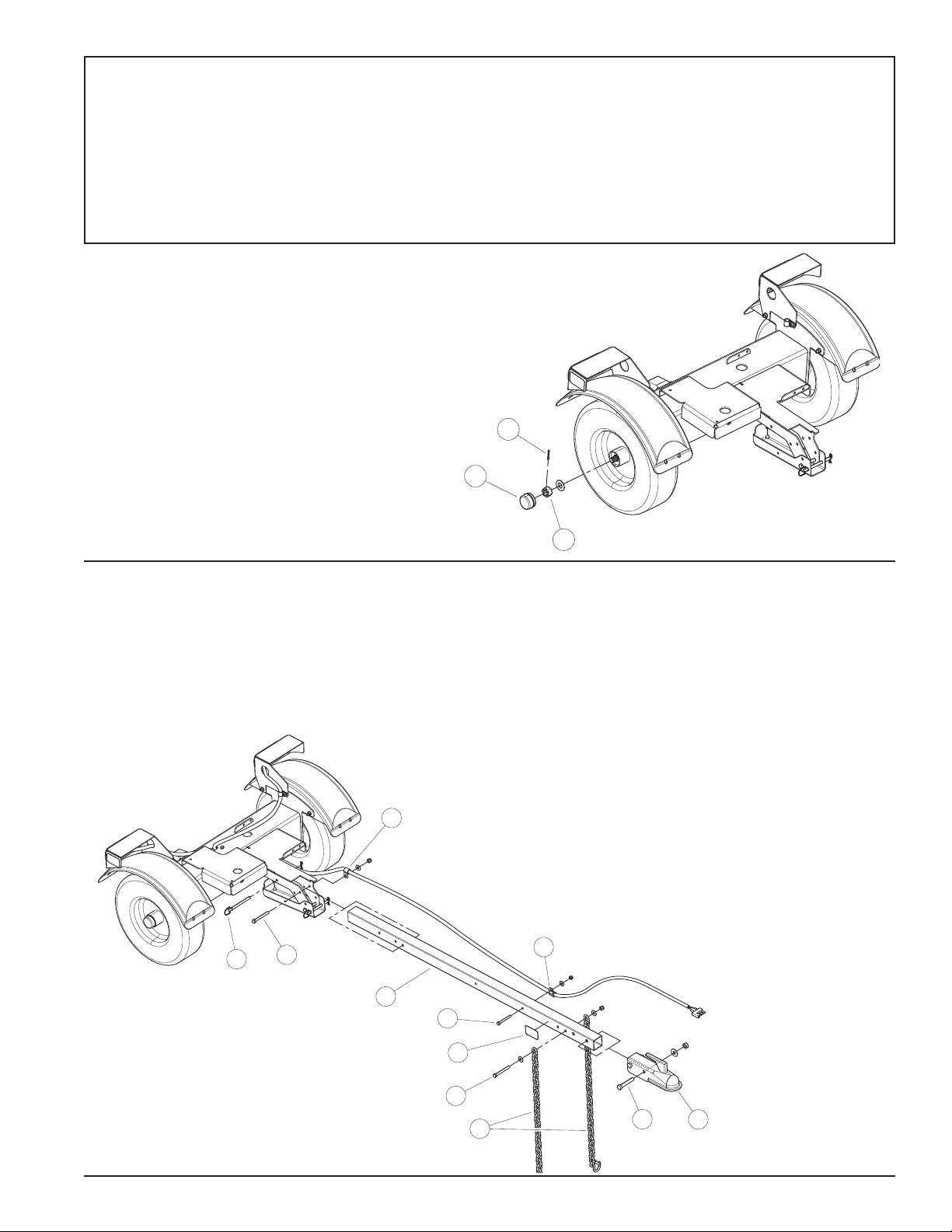
ATTACH WHEELS (FIGURE 1)
1. Attach wheels to trailer using 3/4"-16 slotted nuts
(1), washers, 5/32" cotter pins (2) and dust caps
(3). Using 3/4" wrench, tighten slotted nut until
resistance is felt when trying to spin wheel. At that
point, back the nut off slightly until slot in nut aligns
with cotter pin hole on axle spindle.
2. Insert cotter pin, bend tabs to secure slotted nut
on spindle and install dust cap.
Figure 1
TRAILER ASSEMBLY INSTRUCTIONS
(FIGURE 2)
1. Place hitch pole (1) into trailer frame. Route trailer
light harness through the two provided coated clamps
(2). (Extend trailer leg for more stability while securing
hitch.)
Figure 2
2. Now, secure hitch pole to frame using one 3/8 x 3-1/4"
bolt (3), coated clamp, washer and nut at the hole
location detailed in Figure 2 Torque to 28 ft-lbs. Place
3/8" hitch pin (4) in 3/8" hole closest to the trailer.
Also see Figure 2 for location details. This pin can be
removed to allow the hitch to be positioned vertically
for storage purposes. Reinstall pin once the hitch is in
the vertical position.
3. Attach the remaining coated harness clamp (with
harness already routed through it) to hitch pole using
5/16 x 2-3/4" hex bolt (5), washer and nylock nut.
4. Now attach the 2" coupler (6) to the end of the hitch
pole opposite the trailer. Use two 1/2 x 3" bolts (7) and
centerlock nuts.
5. Secure the safety chains (8) to the hitch pole at the
second open hole location behind the coupler. Use the
3/8 x 3-1/4" bolt (3), two washers and one nylock nut.
3 Inch Trailer Instruction Sheet
PN 77374-00
Rev. 112013
Page 2
WARNING
Before inspecting or servicing any part of this machine,
shut off engine, disconnect the spark plug and make sure
all moving parts have come to a complete stop.
BEFORE MOUNTING ONTO TRAILER:
MACHINES SERIAL # C03478 TO CURRENT
1. A hoist or other lifting device will need to be used to lift
the machine into place on trailer.
2. The following are the approximate weights of the
chipper/shredders:
SC3265 - 285 lbs. (129.3 kg)
SC3305 - 255 lbs. (116 kg)
SC3305E (w/o battery) - 255 lbs (116 kg)
SC3342 - 255 lbs. (116 kg)
Ensure that the lifting device used is rated and certied to
lift more than the weight of the machine.
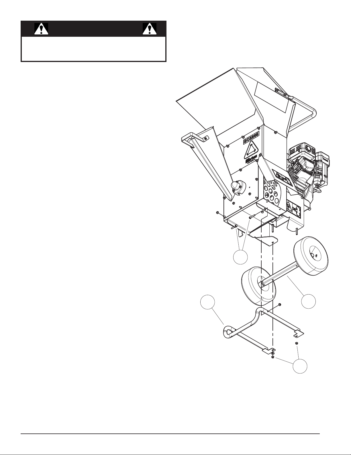
3. FOR 3-INCH CHIPPER/SHREDDERS C03478 AND
ABOVE, remove the metal leg (1) and axle (4) by first
removing the two 5/16 x 1-3/4" bolts (2), washers and
nuts closest to the chipper chute on the leg support.
4. Remove two 5/16" flange nuts (3) and remove support
leg and axle.
5. Use new hardware.
1
2
4
3
Figure 1. Chipper/Shredder C03478 and above
3 Inch Trailer Instruction Sheet
Page 3
WARNING
Before placing machine onto trailer, secure the trailer
in a manner that it will not move while mounting.
WARNING
Before mounting machine to trailer, shut off power
source and remove key on engine, disconnect the
battery cables (if applicable) and make sure all moving
parts have come to a complete stop and the machine
has completely cooled down.
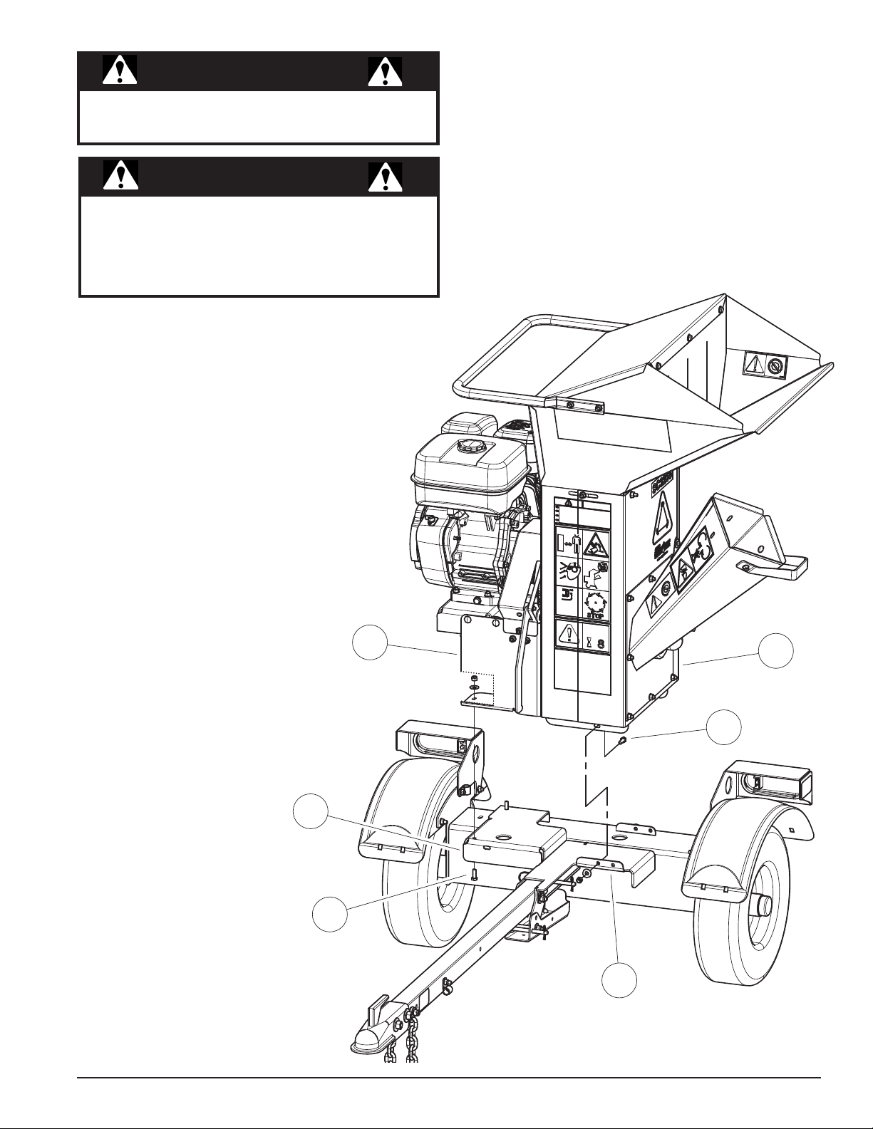
MOUNTING MACHINE ON TRAILER:
REAR DISCHARGE CONFIGURATION-
MACHINES SERIAL # C03478 TO CURRENT
1. Orientate the machine so the
discharge door is facing toward the
rear of trailer.
2. Align hole on engine mount base (1)
of machine to hole on front right plate
(2) of trailer. Also align hole on base
of housing (3) to inside hole of front
left mounting flange (4).
3. Secure machine to trailer using four
5/16 x 7/8" hex bolts (5) washers and
nylock nuts.
2
5
1
3
5
3 Inch Trailer Instruction Sheet
4
Figure 3
Page 4

WARNING
Before placing machine onto trailer, secure the trailer
in a manner that it will not move while mounting.
MOUNTING MACHINE ON TRAILER:
FRONT DISCHARGE CONFIGURATION-
MACHINES SERIAL # C03478 TO CURRENT
1. A hoist or other lifting device will
need to be used to lift the machine
into place on trailer.
2. The following are the approximate
weights of the chipper/shredders:
SC3265 - 285 lbs. (129.3 kg)
SC3305 - 255 lbs. (116 kg)
SC3305E (w/o battery) - 255
lbs (116 kg)
SC3342 - 255 lbs. (116 kg)
Ensure that the lifting device used is
rated and certied to lift more than
the weight of the machine.
3. Place the engine mount bracket
(1) at outside hole of front left
mounting flange (2) and outside
hole of rear mounting flange (3).
Make sure tabs of engine mount
bracket are to the outside of the
flanges. Secure using two 5/16 x
7/8" bolts (4), washers and nylock
nuts.
4. Orientate the machine so the
discharge door is facing toward the
front of trailer.
5. Align holes on base of housing (5)
to center slotted hole on front right
plate (6) of trailer. Also align holes
in engine mount base (7) to engine
mount bracket (1).
6. Once all holes are aligned properly,
secure with four 5/16 x 7/8" bolts
(4), washers and nylock nuts.
7
5
1
4
4
4
6
3
3 Inch Trailer Instruction Sheet
2
Figure 4
Page 5

NOTE
If you have an older model chipper/shredder, you will
have to cut off the existing metal leg before installing
the kit. Newer models have a detachable leg. Choose
the instructions below that are appropriate for your
machine
BEFORE MOUTING ONTO TRAILER:
MACHINES SERIAL # 707865 TO C03262
1. A hoist or other lifting device will need to be used to lift
the machine into place on trailer.
2. The following are the approximate weights of the
chipper/shredders:
SC3265 - 285 lbs. (129.3 kg)
SC3305 - 255 lbs. (116 kg)
SC3305E (w/o battery) - 255 lbs (116 kg)
SC3342 - 255 lbs. (116 kg)
Ensure that the lifting device used is rated and certied to
lift more than the weight of the machine.
3. FOR 3-INCH CHIPPER/SHREDDERS SN 707865 TO
C03262, remove the metal leg (1) by removing the four
5/16" nuts (2) and washers. Also remove the nut and
washer from the middle lower bolt.
4. Keep and reuse all of the nuts (2) and washers; Discard
the metal leg.
2
1
BEFORE MOUNTING ONTO TRAILER:
MACHINES SERIAL # 707807 & BELOW
1. A hoist or other lifting device will need to be used to lift
the machine into place on trailer.
2. The following are the approximate weights of the
chipper/shredders:
SC3265 - 285 lbs. (129.3 kg)
SC3305 - 255 lbs. (116 kg)
SC3305E (w/o battery) - 255 lbs (116 kg)
SC3342 - 255 lbs. (116 kg)
Ensure that the lifting device used is rated and certied to
lift more than the weight of the machine.
3. FOR 3-INCH CHIPPER/SHREDDERS SN 707807 AND
BELOW, cut the leg (1) off with a hacksaw or other
saw appropriate for cutting metal. Make the cut
approximately 1/4" - 1/2" from the chipper frame.
4. Discard metal leg.
5. Remove the three 5/16" nuts (2) and washers.
2
1
3 Inch Trailer Instruction Sheet
Page 6

WARNING
1-3/8"
1"
11/32 TO 3/8
HOLE DIAMETER
Before placing machine onto trailer, secure the trailer
in a manner that it will not move while mounting.
MOUNTING MACHINE ON TRAILER:
REAR DISCHARGE - MACHINES WITH
SERIAL # 707807 & BELOW; # 707865 TO
C03262
1. Using a 11/32" to 3/8" size drill bit, drill holes in housing
at locations and measurements detailed in Figures 6
& 7.
2. Attach the 13.13" engine mount bracket (1) aligned to
holes on front right plate (4) of the trailer securing with
5/16 x 7/8" bolts (3), washers and nuts.
3. Lower machine onto trailer with 13.13" engine mount
bracket holes aligned to new drill holes on housing
(2). Secure using two 5/16 x 7/8" bolts (3), washers
and nuts.
4. Install corner bracket (5) on threaded stud (6) at front
panel location using 5/16" nut and washer. Also secure
at inside hole of left trailer plate flange (7)
*When securing slotted holes use a washer on the bolt side.
Figure 6
Figure 7
DRILL
HOLES
6
2
3
1
7
5
3
4
Figure 5
3 Inch Trailer Instruction Sheet
Page 7

WARNING
1-3/8"
1"
11/32 TO 3/8
HOLE DIAMETER
Before placing machine onto trailer, secure the trailer
in a manner that it will not move while mounting.
MOUNTING MACHINE ON TRAILER:
FRONT DISCHARGE - MACHINES WITH
SERIAL # 707807 & BELOW; # 707865 TO
C03262
1. Using a 11/32" to 3/8" size drill bit, drill holes in housing
at locations and measurements detailed in Figures 6
& 7.
2. Once holes are drilled, attach the 11.5" engine mount
bracket (1) to outside hole of front left trailer panel
flange (2) using two 5/16 x 7/8" bolts (3), washers and
nuts.
3. Mount the 13.13" bracket (4) to machine housing (5) at
newly drilled hole location using two 5/16 x 7/8" bolts,
washer and nuts.
4. Set machine onto trailer aligning holes in brackets and
secure bracket to bracket using two 5/16 x 7/8" bolts,
washers and nuts.
5. Install corner bracket (6) to threaded stud (7) with 5/16
washer and nut, and also to trailer frame (8) at rear
right location.
*When securing slotted holes use a washer on the bolt side.
5
7
3
Figure 6
3
6
4
1
3
3
DRILL
HOLES
Figure 7
2
8
Figure 8
3 Inch Trailer Instruction Sheet
Page 8

ECHO BEAR CAT
Phone: 701.282.5520 • Toll Free: 888.645.4520 • Fax: 701.282.9522
237 NW 12th Street, West Fargo, ND 58078-0849
E-mail: service@bearcatproducts.com • sales@bearcatproducts.com
www.bearcatproducts.com
 Loading...