


 Loading...
3 inch chipper/SHREDDER
sc3206 (70050) - B&S 205 cc sc3305 (70080) - B&S 305 cc SC3305E (70085) - B&S 305 cc Elec SC3240 (70380) - HONDA 240 cc
SC3240T (70580) - HONDA 240 cc Tow SC3342 (75311) - B&S 342 cc
SC3270 - HONDA 270 cc SC3270T - HONDA 270 cc TOW
Manual P/N 14846-00
Rev. 021308
Companion to P/N 14849-00
SN Range: 705134 - A08786
VIN Range: 5VJAA00137W000009 - 5VJAA0012AW002577
owner's manual
ENGLI SH
l
spañoe
FR NÇA A SI

Before You Begin
DEAR ECHO BEAR CAT CUSTOMER
Thank you for purchasing a ECHO Bear Cat product. The ECHO Bear Cat line is designed, tested, and manufactured to give years of dependable performance. To keep your machine operating at peak efficiency, it is necessary to adjust it correctly and make regular inspections. The following pages will assist you in the operation and maintenance of your machine. Please read and understand this manual before operating your machine.
If you have any questions or comments about this manual, please call us toll-free at 1-800-247-7335.
If you have any questions or problems with your machine, please call or write your local authorized ECHO Bear Cat Dealer.
This document is based on information available at the time of its publication. ECHO Bear Cat is continually making improvements and developing new equipment. In doing so, we reserve the right to make changes or add improvements to our product without obligation for equipment previously sold.
PLEASE SEND US YOUR WARRANTY CARD
Awarranty card is included in your owner's kit packaged with your machine. Please take the time to fill in the information requested on the card. When you send your completed card to us, we will register your machine and start your coverage under our limited warranty.
FOR MACHINE SERVICE OR PARTS:
For service assistance, contact your nearest authorized ECHO Bear Cat dealer or the factory. For parts, contact your authorized dealer. Your dealer will need to know the identification number of your machine to provide the most efficient service. See below for information on how to identify and record the identification number for your machine.
FOR ENGINE SERVICE OR PARTS:
Forengineserviceorparts,contactyournearestauthorized engine dealer. ECHO Bear Cat does not handle any parts, repairs or warranties for engines.
ORDERING PARTS
Only genuine ECHO Bear Cat replacement parts should be used to repair the machine. Replacement parts manufactured by others could present safety hazards, even though they may fit on this machine. Replacement parts are available from your ECHO Bear Cat dealer.
Provide the following when ordering parts:
The SERIAL NUMBER OR VIN of your machine. The PART NUMBER of the part.
The PART DESCRIPTION.
The QUANTITY needed.
IDENTIFICATION NUMBER LOCATION
Your machine will have either a serial number or vehicle identification number (VIN). VINs are located on the left side of the trailer frame near the hitch. They are 17-digit numbers of the format: 5VJAA001XXWXXXXX. Serial numbers are located on the machine body. They are
6-digit numbers.
Record your identification number in the space provided and on the warranty registration card.
SERIAL NUMBER or vin
How to contact ECHO Bear Cat
address |
Phone |
hours |
||
|
|
|
|
|
237 NW 12th Street |
800.247.7335 |
sales@bearcatproducts.com |
Monday - Friday, |
|
P.O. Box 849 |
701.282.5520 |
8 am to 5 pm |
||
service@bearcatproducts.com |
||||
West Fargo, ND 58078 |
Fax: 701.282.9522 |
Central Time |
||
|
||||
|
|
|
|
*Original Instructions
© 2008, Crary industries, all rights reserved. produced and printed in the u.s.a.

LIMITED WARRANTY
This warranty applies to all AG and Outdoor Power Equipment manufactured by Crary Industries.
Crary Industries warrants to the original owner each new Crary Industries product to be free from defects in material and workmanship, under normal use and service. The warranty shall extend 1 year from date of delivery for income producing (commercial) applications and 2 years from date of delivery for non-income producing (consumer) use of the product. The product is warranted to the original owner as evidenced by a completed warranty registration on file at Crary Industries. Replacement parts are warranted for (90) days from date of installation.
The warranty registration must be completed and returned to Crary Industries within 10 days of delivery of the product to the original owner or the warranty will be void.
In the event of a failure, return the product, at your cost, along with proof of purchase to the selling Crary Industries dealer. Crary Industries will, at its option, repair or replace any parts found to be defective in material or workmanship. Warranty on any repairs will not extend beyond the product warranty. Repair or attempted repair by anyone other than a Crary Industries dealer as well as subsequent failure or damage that may occur as a result of that work will not be paid under this warranty. Crary Industries does not warrant replacement components not manufactured or sold by Crary Industries.
This warranty applies only to parts or components that are defective in material or workmanship.
This warranty does not cover normal wear items including but not limited to bearings, belts, pulleys, filters and chipper knives.
This warranty does not cover normal maintenance, service or adjustments.
This warranty does not cover depreciation or damage due to misuse, negligence, accident or improper maintenance.
This warranty does not cover damage due to improper setup, installation or adjustment. This warranty does not cover damage due to unauthorized modifications of the product.
Engines are warranted by the respective engine manufacturer and are not covered by this warranty.
Crary Industries is not liable for any property damage, personal injury or death resulting from the unauthorized modification or alteration of a Crary product or from the owner’s failure to assemble, install, maintain or operate the product in accordance with the provisions of the Owner’s manual.
Crary Industries is not liable for indirect, incidental or consequential damages or injuries including but not limited to loss of crops, loss of profits, rental of substitute equipment or other commercial loss.
This warranty gives you specific legal rights. You may have other rights that may vary from area to area.
CraryIndustriesmakesnowarranties,representationsorpromises,expressedorimpliedastotheperformance of its products other than those set forth in this warranty. Neither the dealer nor any other person has any authority to make any representations, warranties or promises on behalf of Crary Industries or to modify the terms or limitations of this warranty in any way. Crary Industries, at its discretion, may periodically offer limited, written enhancements to this warranty.
Crary Industries reserves the right to change the designand/or specifications of its products at any time without obligation to previous purchasers of its products.
ENGLI SH

|
TABLE OF CONTENTS |
|
DESCRIPTION |
PAGE |
|
Safety................................................................................................................. |
1 |
|
1.1 |
SAFETY ALERT SYMBOL..................................................................................... |
1 |
1.2 |
EMISSION INFORMATION................................................................................... |
1 |
1.3 |
before operating.......................................................................................... |
2 |
1.4 |
OPERATIon SAFETY........................................................................................... |
2 |
1.5 |
MAINTENANCE and storage safety........................................................... |
3 |
1.6 |
towing safety................................................................................................. |
3 |
1.7 |
battery safety................................................................................................ |
3 |
1.8 |
safety decal locations............................................................................... |
4 |
1.9 |
safety decals ................................................................................................. |
5 |
Assembly............................................................................................................ |
6 |
|
2.1 |
INSTALLING THE HANDLE.................................................................................. |
6 |
2.2 |
INSTALLING THE hopper.................................................................................. |
6 |
2.3 |
INSTALLING the chipper chute extension.............................................. |
6 |
2.4 |
INSTALLING discharge assembly ............................................................... |
6 |
2.5 |
FILL THE fuel TANK........................................................................................... |
7 |
2.6 |
add oil.................................................................................................................. |
7 |
2.7 |
install a battery (sc3305e ONLY)................................................................ |
7 |
2.8 |
INSTALLING THE wheels, jack and hitch |
|
|
(sc3240t and sc3270t ONLY)........................................................................... |
7 |
Features & Controls................................................................................... |
8 |
|
Operation........................................................................................................ |
10 |
|
4.1 |
Starting recoil models.............................................................................. |
10 |
4.2 |
Starting electric models ....................................................................... |
10 |
4.3 |
Stopping the Chipper/Shredder............................................................. |
11 |
4.4 |
operating the chipper/shredder........................................................... |
11 |
Service & Maintenance.............................................................................. |
12 |
|
5.1 |
maintenance schedule.............................................................................. |
12 |
5.2 |
chipper BLADE maintenance...................................................................... |
13 |
5.3 |
removing the blades................................................................................... |
13 |
5.4 |
sharpening the blades.............................................................................. |
13 |
5.5 |
installing the blades................................................................................. |
14 |
5.6 |
adjusting the CHIPPER ANVIL..................................................................... |
14 |
5.7 |
replacing the shredder knives............................................................. |
14 |
5.8 |
changing the discharge screen............................................................ |
15 |
5.9 |
Clearing a plugged rotor........................................................................ |
15 |
5.10 Belt guide adjustments........................................................................... |
15 |
|
5.11 remove/Replace Drive Belt..................................................................... |
16 |
|
5.12 Removing the Rotor.................................................................................. |
16 |
|
5.13 TRAILER SERVICE TIPS................................................................................... |
16 |
|
5.14 lubrication.................................................................................................... |
16 |
|
Troubleshooting......................................................................................... |
17 |
|
Specifications............................................................................................... |
18 |
|
7.1 |
size specifications...................................................................................... |
18 |
7.3 |
special torque requirements................................................................. |
21 |
7.2 |
bolt torque.................................................................................................... |
22 |
iv |
3 INCH CHIPPER/SHREDDER |
|
1 Safety
Section
1.1 SAFETY ALERT SYMBOL |
|
1.2 EMISSION INFORMATION |
The Owner/Operator’s manual uses this symbol to alert you of potential hazards. Whenever you see this symbol, read and obey the safety message that follows it. Failure to obey the safety message could result in personal injury, death or property damage.
DANGER
Indicates an imminently hazardous situation that, if not avoided, will result in death or serious injury.
WARNING
Indicates a potentially hazardous situation that, if not avoided, could result in death or serious injury.
CAUTION
Indicates a potentially hazardous situation that, if not avoided, may result in minor or moderate injury.
Under California Law and the laws of several other states, you are not permitted to operate an internal combustion engine using hydrocarbon fuels on any forest covered, brush covered or grass covered land or on land covered with grain, hay or other flammable agricultural crops, without an engine spark arrester in continuous effective working order.
The engine on your power equipment, like most outdoor
power |
equipment, is |
||
an internal combustion |
|||
engine |
|
that |
burns |
gasoline |
|
or |
diesel |
fuel |
(hydrocarbons). |
||
Therefore, |
your |
power |
|
equipment |
must |
be |
|
equipped |
|
with a |
spark |
arrester |
|
muffler |
in |
continuous |
effective |
||
working order. The spark arrester must be attached to the engine exhaust system in such a manner that flames or heat from the system will not ignite flammable material.
Failure of the owner/operator of the equipment to comply with this regulation is a misdemeanor under California law and may also be a violation of other state and/or federal regulations, laws, ordinances, or codes. Contact your local fire marshal or forest service for specific information about which regulations apply in your area.
Thestandardmufflerinstalledontheengineisnotequipped with a spark arrester. One must be added before using this machine in an area where a spark arrester is required by law. Contact the local authorities if these laws apply to you. See your authorized engine dealer for spark arrester options.
ENGLI SH
3 INCH CHIPPER/SHREDDER |
1 |
SAFETY
1.3 before operating |
|
1.4 OPERATIon SAFETY |
|
|
|
1.Read and understand this owner’s manual. Be completely familiar with the controls and the proper use of this equipment.
2.Familiarize yourself with all of the safety and operating decals on this equipment and on any of its attachments or accessories.
3.Keep safety decals clean and legible. Replace missing or illegible safety decals.
4.Obtain and wear safety glasses and use hearing protection at all times when operating this machine.
5.Avoid wearing loose fitted clothing. Never operate this machine while wearing clothing with drawstrings that could wrap around or get caught in the machine.
6.Do not operate this machine if you are under the influence of alcohol, medications, or substances that can affect your vision, balance or judgment. Do not operate if tired or ill. You must be in good health to operate this machine safely.
7.Do not operate this equipment in the vicinity of bystanders. Keep the area of operation clear of all persons, particularly small children. It is recommended that bystanders keep at least 50 feet (15 meters) away from the area of operation.
8.Do not allow children to operate this equipment.
9.Use only in daylight or good artificial light.
10.Do not run this equipment in an enclosed area. Engine exhaust contains carbon monoxide gas, a deadly poison that is odorless, colorless and tasteless. Do not operate this equipment in or near buildings, windows or air conditioners.
11.Always use an approved fuel container. Do not remove gas cap or add fuel when engine is running. Add fuel to a cool engine only.
12.Do not fill fuel tank indoors. Keep open flames, sparks, smoking materials and other sources of combustion away from fuel.
13.Do not operate machine without guards, deflectors, doors, and shields in place. Failure to do so may cause serious injury or death.
14.Keep all guards, deflectors, doors, and shields in good working condition.
15.Before inspecting or servicing any part of this machine, shut off the machine and make sure all moving parts have come to a complete stop. Disconnect the battery and remove the ignition key where applicable.
16.Check that all screws, nuts, bolts, and other fasteners are secured, tightened and in proper working condition before starting the machine.
17.Do not transport or move machine while it is operating or running.
1.Always stand clear of discharge area when operating this machine. Keep face and body away from feed and discharge openings.
2.Keep hands and feet out of feed  and discharge openings while
machine is operating to avoid
serious personal injury. Stop and allow machine to come to a complete stop before clearing obstructions.
3.Set up your work site so you are not endangering traffic and the public. Take great care to provide adequate warnings.
4.Do not climb on machine when operating. Keep proper balance and footing at all times.
5.Check cutting chamber to verify it is empty before starting the machine.
6.The disk will continue to rotate after being disengaged. Shut off the machine and make sure all moving parts have come to a complete stop before inspecting or servicing any part of the machine. Disconnect the battery and remove the ignition key if applicable.
7.Do not insert branches with a diameter larger than the max chipper capacity into machine or machine damage may occur.
8.When feeding material into machine, do not allow metal, rocks, bottles, cans or any other foreign material to be fed into the machine.
9.Ensure debris does not blow into traffic, parked cars, or pedestrians.
10.Keep the machine clear of debris and other accumulations.
11.Do not allow processed material to build up in the discharge area. This may prevent proper discharge and can result in kickback of material through the feed opening.
12.If the machine becomes clogged, the cutting mechanism strikes any foreign object, or the machine starts vibrating or making an unusual noise, shut off machineimmediatelyandmakesureall moving parts have come to a complete stop.Disconnectthebatteryandremove
the ignition key if applicable. After the machine stops: A) Inspect for damage, B) Replace or repair any damaged parts, and C) Check for and tighten any loose parts.
13.On electric start models, disconnect cables from battery before doing any inspection or service. Remove key.
14.Check blade bolts for proper torque after every 8 hours of operation. Check blades and rotate or resharpen daily or as required to keep blades sharp. Failure to do so may cause poor performance, damage or personal injury and will void the machine warranty.
2 |
3 INCH CHIPPER/SHREDDER |
SAFETY
1.5 MAINTENANCE and storage safety |
|
1.7 battery safety |
1.Before inspecting, servicing, storing, or changing an accessory, shut off the machine and make sure all moving parts have come to a complete stop.
Disconnect the battery and remove the ignition key where applicable.
2.Replace any missing or unreadable safety decals. Refer to the safety decal section for part numbers.
3.Allow machine to cool before storing in an enclosure.
4.Store the machine out of reach of children and where fuel vapors will not reach an open flame or spark.
5.Never store this machine with fuel in the fuel tank inside a building where fumes may be ignited by an open flame or spark. Ignition sources can be hot water and space heaters, furnaces, clothes dryers, stoves, electric motors, etc.
6.Drain the fuel and dispose of it in a safe manner for storage periods of three months or more.
1.6towing safety
1.Rotate the discharge tube to face the opposite direction of the towing vehicle before towing.
2.Insert transport safety pin and clip, and set brake handle to locked position, if applicable.
3.Connect hitch safety chains. Tighten trailer hitch bolts. Do not attempt to tow the trailer if the vehicle is not equipped with a 2” (50 mm) ball.
4.Do not exceed the maximum towing speed indicated on tire sidewall. Inflate tires to manufacturer’s specifications as stated on the tire sidewall.
5.Optimum towing performance can be achieved by maintaining a horizontal trailer hitch.
6.Check wheel lug bolts periodically to ensure they are tight and secure.
7.Make sure the jack stand and the rear stabilizer (where applicable) on the trailer are in the UP position during towing. Place the jack stand on a level surface and secure it in the DOWN position before using.
8.Never allow passengers to ride on the machine.
9.If applicable, shut off fuel supply when towing.
10.Towing laws may vary in different countries/regions/ states. It is recommended that you contact your local motor vehicle department for any special regulations that pertain to towing and know the laws of any country/ region/state you travel through.
Improperuseandcareofthebatteryonelectricstartmodels can result in serious personal injury or property damage. Always observe the following safety precautions.
Poison/Danger - Causes Severe Burns. The battery contains sulfuric acid. Avoid contact with skin, eyes or clothing. Keep out of reach of children.
•ANTIDOTE-External Contact: Flush immediately with water.
•ANTIDOTE-Internal: Drink a large amount of water or milk. Follow with milk of magnesia, beaten egg or vegetable oil. Call a physician immediately.
•ANTIDOTE-Eye Contact: Flush with water for 15 minutes. Get prompt medical attention.
1.The battery produces explosive gases. Keep sparks, flame or cigarettes away. Ventilate area when charging battery. Always wear safety goggles when working near battery.
2.The battery contains toxic materials. Do not damage battery case. If case is broken or damaged, avoid contact with battery contents.
3.Neutralize acid spills with a baking soda and water solution. Properly dispose of a damaged or worn-out battery. Check with local authorities for proper disposal methods.
4.Do not short circuit battery. Severe fumes and fire can result.
5.Before working with electrical wires or components, disconnect battery ground (negative) cable first.
Disconnect positive cable second. Reverse this order when reconnecting battery cables.
DANGER / POISON
FLUSH EYES
IMMEDIATELY
WITH WATER
EYES |
|
|
NO |
|
SULFURIC |
|
|
|
|
|
|
|
|||
EXPLOSIVE GASES |
|
|
|
ACID |
|
GET |
|
|
|
|
|
||||
CAN CAUSE |
|
• SPARKS |
|
CAN CAUSE |
|
MEDICAL |
|
|
|
|
|||||
|
|
|
|||||
BLINDNESS OR |
|
• |
FLAMES |
|
BLINDNESS OR |
|
HELP |
|
|
|
|||||
INJURY |
|
• |
SMOKING |
|
SEVERE BURNS |
|
FAST |
|
|
|
|||||
|
|
|
|||||
KEEP OUT OF THE REACH OF CHILDREN. DO NOT TIP. KEEP VENT CAPS TIGHT AND LEVEL.
ENGLI SH
3 INCH CHIPPER/SHREDDER |
3 |
SAFETY
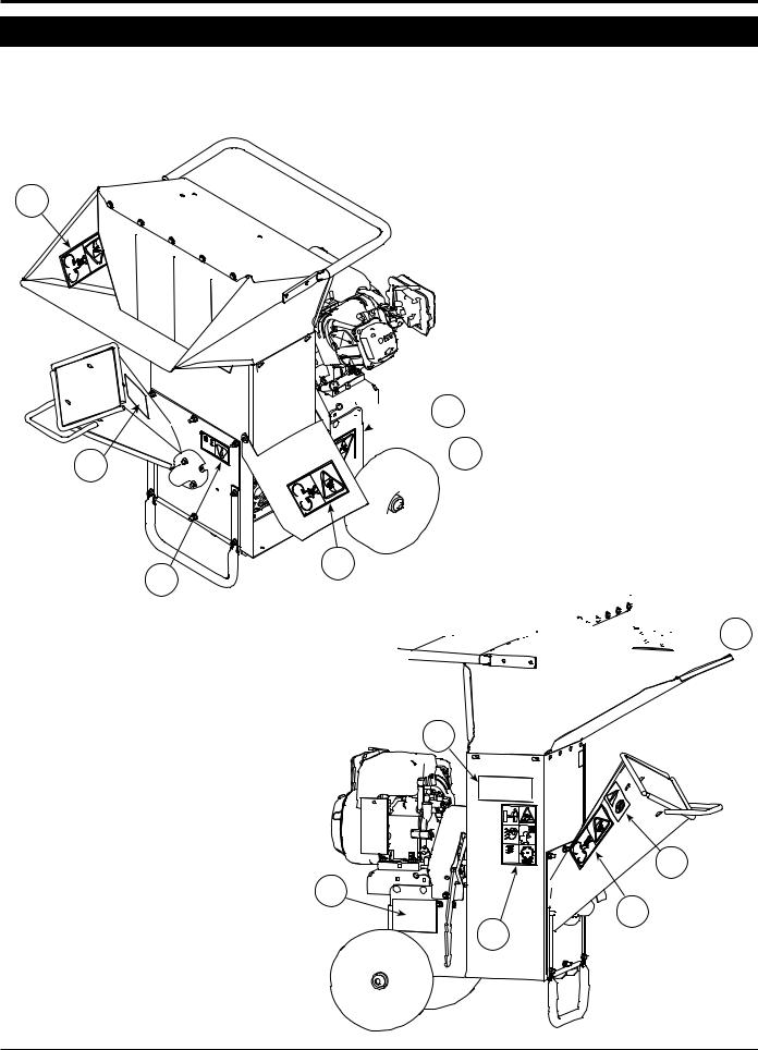
1.8 safety decal locations
The numbers below correspond to the decals in Section 1.9. Familiarize yourself with all of the safety and operational decals on the machine and the associated hazards. See the engine owner’s manual or contact the engine manufacturer for engine safety instructions and decals. Make certain that all safety and operating decals on this machine are kept clean and in good condition. Decals that need replacement must be applied to their original locations.
2
7
4
model sc3305 shown here


 1
1

 2
2
2


 3
3
7
6
5


 2 8
2 8 


4 |
3 INCH CHIPPER/SHREDDER |
SAFETY
1.9 safety decals
See Section 1.8 for decal locations. Familiarize yourself with all of the safety and operating decals on the machine and the associated hazards. See the engine owner’s manual or contact the engine manufacturer for engine safety instructions and decals. Make certain that all safety and operational decals on this machine are kept clean and in good condition. Decals that need replacement must be applied to their original locations.
1 P/N 12174
DO NOT OPERATE MACHINE
WITHOUT SHIELDS IN PLACE. FAILURE TO DO SO MAY CAUSE SERIOUS INJURY OR DEATH.
6 P/N 14938-00
DONOTINSERTBRANCHES
LARGER THAN 3 INCHES IN
DIAMETER INTO CHIPPER.
MACHINE DAMAGE MAY
OCCUR. REFER TO OWNERS MANUAL FOR OPERATING INSTRUCTIONS AND RECOMMENDATIONS.
2 |
P/N 12175 |
7 P/N 14942-00 |
||
KEEP HANDS AND FEET |
|
|||
OUT |
OF |
INLET |
AND |
|
DISCHARGE OPENINGS |
|
|||
WHILE |
|
MACHINE |
IS |
|
OPERATING TO AVOID |
|
|||
SERIOUS |
PERSONAL |
|
||
INJURY. STOP AND ALLOW MACHINE TO COME TO A
COMPLETE STOP BEFORE CLEARING OBSTRUCTIONS.
3 P/N 12176
DO NOT INSERT
BRANCHES LARGER
THAN 3/4 INCH INTO
SHREDDER OR MACHINE
DAMAGE MAY OCCUR.
4 |
P/N 12250 |
|
CHECK |
BLADE |
BOLTS |
FOR PROPER |
TORQUE |
|
AFTER |
EVERY 8 |
HOURS |
OF OPERATION. |
CHECK |
|
BLADES AND ROTATE OR |
||
RESHARPEN DAILY OR AS REQUIRED TO KEEP BLADES SHARP. REFER TO OWNERS MANUAL FOR INSTRUCTIONS. FAILURE TO DO SO MAY CAUSE POOR PERFORMANCE, DAMAGE OR PERSONAL INJURY AND WILL VOID THE
MACHINE WARRANTY.
5 |
P/N 14703-00 |
|
LOWER |
LEVER SLOWLY TO |
|
ENGAGECHIPPER. PULLLEVER |
||
UP TO DISENGAGE CHIPPER. |
||
CHIPPER/SHREDDER |
ROTOR |
|
WILL CONTINUE TO |
ROTATE |
|
WHEN CLUTCH IS DISENGAGED. STOP ENGINE AND REMOVE SPARK PLUG WIRE BEFORE CLEANING DEBRIS FROM DISCHARGE AREA OR SERVICING THIS MACHINE. DO NOT OPERATE WITHOUT DISCHARGE SCREEN, INLET FLAPS AND ALL SHIELDS IN PLACE.
8 P/N 14965-00
DO NOT OPERATE THIS
EQUIPMENT IN THE
VICINITYOFBYSTANDERS.
DONOTALLOWCHILDREN
TO OPERATE THIS
EQUIPMENT.
OBTAIN AND WEAR
SAFETY GLASSES AND USE HEARING PROTECTION AT ALL TIMES WHEN OPERATING
THIS MACHINE.
BEFORE INSPECTING OR SERVICING ANY PART OF THIS MACHINE, SHUT OFF POWER SOURCE, DISCONNECT SPARK PLUG WIRE FROM SPARK PLUG AND MAKE SURE ALL MOVING PARTS HAVE
COME TO A COMPLETE STOP.
ALWAYS STAND CLEAR OF DISCHARGE AREA WHEN OPERATING THIS MACHINE. KEEP FACE AND BODY AWAY FROM FEED AND DISCHARGE OPENINGS.
WHEN FEEDING SHREDDABLE MATERIAL INTO CHIPPER, DO NOT ALLOW METAL, ROCKS, BOTTLES, CANS OR ANY OTHER FOREIGN MATERIAL TO BE FED INTO CHIPPER OR
SHREDDER.
BEFORE INSPECTING OR SERVICING ANY PART OF THIS MACHINE, SHUT OFF POWER SOURCE, DISCONNECT SPARK PLUG WIRE FROM SPARK PLUG AND MAKE SURE ALL MOVING PARTS HAVE COME TO A COMPLETE STOP.
ENGLI SH
3 INCH CHIPPER/SHREDDER |
5 |
2 Assembly
Section
WARNING
If any bolts or nuts are dropped in the machine, be sure to remove them before starting the machine. Remove items from the shredder area by removing the discharge screen.
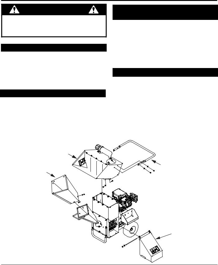
2.1INSTALLING THE HANDLE
1.Remove the chipper/shredder and hopper assembly from the shipping box and pallet.
2.Install four 5/16" X 3/4" bolts so the head of the bolt is located on the inside of the hopper. Fasten bolts with 5/16" nylock nuts and 5/16" flat washers.
2.2INSTALLING THE hopper
1.Assemble the hopper assembly to the frame so the handle is located above the engine and the opening is toward the chipper chute.
2.Install twelve 5/16" X 3/4" bolts so the head of the bolt is inside the hopper. Fasten bolts with 5/16" flat washers and 5/16" nylock nuts.
2.3 INSTALLING the chipper chute extension
NOT AVAILABLE ON ALL MODELS
1.Place the chipper chute extension onto the chute.
Line up the four holes located on the bottom of the extension and the top of the chute.
2.Install four 5/16" X 3/4" bolts so the head of the bolt is located on the inside of the chipper chute. Fasten bolts with 5/16" nuts. Tighten nut until snug against the chute extension.
2.4INSTALLING discharge assembly
Not available on all models
1.Place the discharge weldment onto the chipper. The holes on the weldment should line up with holes on the chipper.
2.Secure the top of the discharge weldment using one 5/16" x 7-1/2" bolt (narrow door) or one 5/16" x 10" bolt (wide door) and 5/16" nuts. Tighten to proper torgue
3.Secure the bottom of the discharge weldment using two 5/16" x 3/4" bolts and 5/16" nuts. The head of the bolt should be located inside the discharge assembly. Tighten to the proper torque.
HOPPER |
|
CHIPPER |
|
EXTENSION |
HANDLE |
(WHERE AVAILABLE) |
DISCHARGE ASSEMBLY
(WHERE AVAILABLE)
6 |
3 INCH CHIPPER/SHREDDER |
ASSEMBLY
2.5 FILL THE fuel TANK
WARNING
Gasoline and diesel fuels are highly flammable and their vapors are explosive. To prevent personal injury or property damage:
Store fuel only in approved containers, in well ventilated, unoccupied buildings, away from sparks or flames. A container with a capacity of 2 gallons or less with a pouring spout is recommended. Do not fill the fuel tank while the engine is hot or running, since spilled fuel could ignite if it comes in contact with hot parts or sparks from ignition. Do not start the engine near spilled fuel. Never use fuel as a cleaning agent. DO NOT MIX OIL WITH FUEL.
Use only those types of fuels that are recommended in your engine owner’s manual.
To add fuel:
1.Stopengine,waitforallpartstostopmovinganddisconnect spark plug wire. Remove key from key switch. Allow the engine and muffler to cool for at least three minutes.
2.Clean area around fuel fill cap and remove cap.
3.Using a clean funnel, fill fuel tank to 1/2” below bottom of filler neck to provide space for any fuel expansion. Install fuel fill cap securely and wipe up any spilled gasoline.
2.6add oil
Check the oil level and, if needed, fill the engine crankcase with the type and amount of oil specified in the engine owner’s manual.
2.7 install a battery (sc3305e ONLY)
You will need to purchase a battery. Choose a battery that meets or exceeds the following specifications:
CCA@ Zero Degree: 200-250
Size: 7-3/4" X 5-3/16" X 7-5/16" BCI Group Size U1
Exide Cutting Edge, Type GT-H
WARNING
To avoid sparks and a possible explosion or fire due to a short circuit, do not touch the positive (+) battery terminal and any surrounding metal with tools, jewelry or other metal objects. When installing battery cables, connect the positive (+) cable first and the negative (-) cable last.
2.8 INSTALLING THE wheels, jack and hitch (sc3240t and sc3270t ONLY)
1.Slide one wheel onto a hub and align the wheel lug holes with the hub lug holes.
2.Thread the wheel bolts into the holes and tighten to the proper torque. Follow an alternating cross pattern when tightening wheel bolts.
3.Repeat for the remaining wheel.
4.Install hitch jack onto hitch pole and install snap pin.
5.Align the hitch pole assembly to the frame and secure using two 3/8" X 2-1/2" bolts, 3/8" flat washers and 3/8" nylock nuts.
ENGLI SH
Figure 2.1 - Briggs Oil Fill
Figure 2.2 - Honda Oil Fill
3 INCH CHIPPER/SHREDDER |
7 |
3 Features & Controls
Section
Understanding how your machine works will help you achieve the best results when using your machine. The following descriptions define the features and controls of your machine.
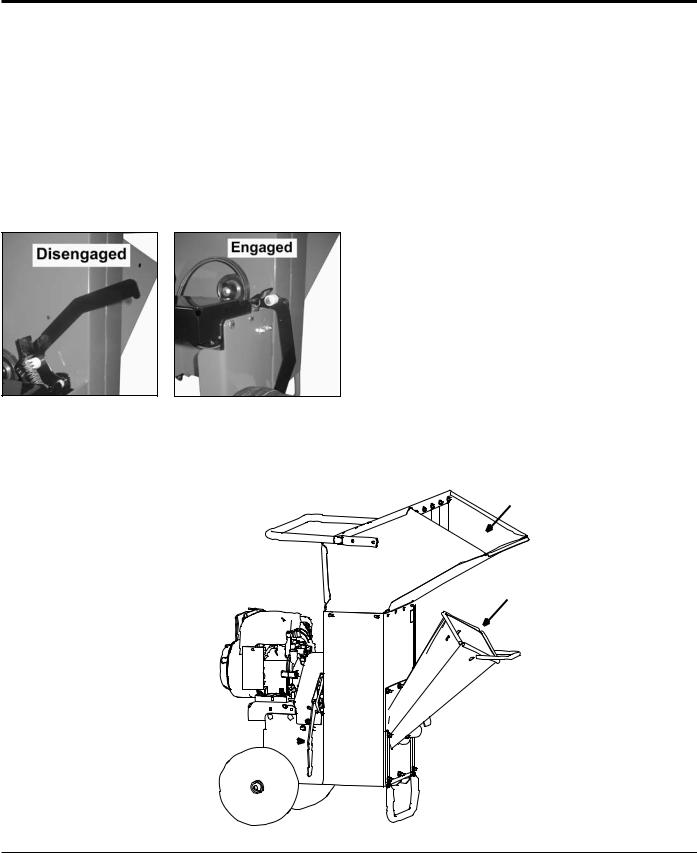
engagement handle
During engine start-up, the engagement handle must be in the disengaged position (Figure 3.1). With engine at full throttle, carefully engage the rotor by slowly pushing the engagement handle down, allowing the rotor to speed up gradually (Figure 3.2). Engaging the clutch too quickly with the engine at full or half throttle will bog down the engine and will shorten the life of the belt. To disengage the rotor, first idle the engine down and then lift the engagement handle up
shredder chute
Materials to be shredded are fed through the shredder chute to the shredder knives.
chipper chute
Materials to be chipped are fed through the chipper chute to the chipper blades.
jack stand
Model SC3240T and sc3270t only
Always have the jack stand retracted from the ground when moving the unit. When in use, be sure the jack stand is down and locked in position with the snap pin.
Figure 3.1 |
Figure 3.2 |
Disengaged Clutch |
Engaged Clutch |
SHREDDER
CHUTE
CHIPPER
CHUTE
ENGAGEMENT 


HANDLE
8 |
3 INCH CHIPPER/SHREDDER |

FEATURES & CONTROLS
engine throttle |
key switch |
Changes engine speed. Push lever to 1/2 throttle for starting. Push lever to slow for idle and warm-up. Push throttle lever to slow throttle to shut engine off. Refer to engine manual for further engine operating instructions. When chipping or shredding, the engine should be at full throttle.
engine choke
Use when starting a cold engine. Move lever to the choke position when starting. Move lever to the run position when engine is running (Figures 3.3 and 3.4). Refer to engine manual for further engine operating instructions.
The key switch is used to start or stop the engine. See Figures 3.5 thru 3.8 for keyswitch locations. Refer to the engine manual for further operating instructions.
ENGLI SH
Figure 3.3 Briggs Throttle and Choke Locations
Figure 3.4 Honda Throttle and Choke Locations
Figure 3.5 Honda On/Off switch
Figure 3.6 Honda Electric Key Switch
Figure 3.7 Briggs Electric On/Off Switch
Figure 3.8 Briggs Commercial On/Off Switch
3 INCH CHIPPER/SHREDDER |
9 |

4 4 Operation
Section
As with any other piece of outdoor equipment, getting the feel for how your machine operates and getting to know the best techniques for particular jobs are important to overall good performance.
CHIPPING OPERATION
The chipping operation takes place on the front of the machine, where hardened steel chipper blades are mounted on a rotating disk assembly. Material fed into the chipper chute is sliced into small chips and propelled out through a discharge tube.
Shredding OPERATION
In this operation, hardened steel shredder knives grind up material fed into the shredder chute. The shredded material then leaves the shredder area by traveling through the discharge screen. The shredded material can be diverted into a container or onto the ground.
WARNING
Move machine to a clear, level area outdoors before starting. Do not operate in the vicinity of bystanders. Make sure cutting chamber is empty before starting.
WARNING
Before operating your machine, be sure you read and understand all safety, controls and operating instructions in this owner's manual and on your machine. Failure to follow these instructions can result in serious injury or property damage.
4.1Starting recoil models
1.Check engine oil level before starting.
2.Place the throttle control midway between the slow and fast positions.
3.Place the choke control into the choke position.
4.Turn the key switch to on (if equipped).
5.Pull the recoil starter until the engine starts. Make sure the starting cord retracts.
6.Move throttle to full position.
7.Slowly push the engagement handle down to engage the chipper/shredder.
For a Cold Engine — Gradually return the choke control to the off position after the engine starts and warms up. The machine may be operated during the warm up period, but it may be necessary to leave the choke partially on until the engine warms up.
For a Warm Engine — Return choke to the off position as soon as engine starts.
4.2 Starting electric models
Do not crank the engine continuously for more than 10 seconds at a time. If the engine does not start, allow a
60 second cool down period between starting attempts.
Failure to follow these guidelines can burn out, or permanently damage, the starter motor.
If the engine develops sufficient speed to disengage the starter but does not keep running (a false start), the engine rotation must be allowed to come to a complete stop before attempting to restart the engine. If the starter is engaged while the flywheel is rotating, damage to the starter may result.
If the starter does not turn the engine over, shut off starter immediately. Do not make further attempts to start the engine until the condition is corrected. Do not jump start using another battery. Follow the steps below to start the machine.
1.Check engine oil level before starting.
2.Place the throttle control midway between the slow and fast positions. Place the choke control into the choke position.
3.Start the engine by activating the key switch. Release the switch as soon as the engine starts.
4.Move throttle to full position.
5.Slowly push the engagement handle down to engage the chipper/shredder.
6.For a Cold Engine — Gradually return the choke control to the off position after the engine starts and warms up. The machine may be operated during the warm up period, but it may be necessary to leave the choke partially on until the engine warms up.
For a Warm Engine — Return choke to the off position as soon as engine starts.
10 |
3 INCH CHIPPER/SHREDDER |

OPERATION
4.3Stopping the Chipper/Shredder
1.Move the throttle to the slow idle position.
2.Disengage the engagement handle.
3.Allow the engine to run at idle for 30-60 seconds; stop the engine by moving the throttle to the low position or turn off ignition.
4.Allow machine to come to a complete stop.
4.4operating the chipper/shredder
WARNING
Read and follow all safety instructions in this manual.
Failure to operate the machine in accordance with the safety instructions MAY RESULT IN PERSONAL
INJURY!
CAUTION
Obtain and wear safety glasses at all times when operating the machine.
Do not wear loose fitting clothing.
The operator should always wear heavy boots, gloves, pants and a long-sleeved shirt.
Use common sense and practice safety to protect yourself from branches, sharp objects, and other harmful objects.
The machine chips and shreds a variety of materials into a more readily decomposed or handled condition. The following guidelines will help you get started.
1.Run unit at full operating speed before starting to chip material.
2.Limbs fed in to the chipper chute must be 3 inches (7.5 cm) in diameter or less. Trim side branches that cannot be bent enough to feed into the chipper chute.
Hold small diameter branches together in a bundle and feed in simultaneously.
3.Material fed into the shredder chute must be ¾ inches (2 cm) in diameter or less. Common shredding materials include grass, leaves, garden refuse, sticks, and small branches.
4.Exclude pieces of metal, rocks, bottles, cans, and other foreign objects when feeding material into the machine.
5.Feed brush from the side of the chipper chute, rather than from the front. Step aside to avoid being hit by the brush moving into the chipper.
6.Place limb, butt end first, into the chipper chute until it contacts the chipper blades. The actual feed rate of the limb into the chipper will depend on the type of material fed and sharpness of the cutting blades.
7.If the engine slows to where it may stall, stop feeding material and allow the engine to recover. Feed material more evenly.
8.If the chipper jams, remove the branch and rotate it before reinserting it into the chute. Alternately insert and retract the limb or insert continuously at a rate that will not kill the engine.
WARNING
Never lean over the chipper chute to push objects into the cutting device. Use a push stick or brush paddle.
Never use shovels or forks to feed brush. They can cause extensive damage if they contact the blades. In addition, metal pieces can be ejected from the chipper chute and cause serious injury or death.
Never feed brush into the chute with your feet.
Never use hands or feet to clear materials that build up in the chute.
9.Do not use the clutch to clear a plugged rotor. This may cause belt damage. Refer to the instructions for clearing a plugged rotor in the Service and Maintenance section.
10.Alternate greener material with dry material to lubricate the chipping blades for longer life and better performance. Chipping dead, dry material will create heat and dull the chipping blades quickly.
11.Sharpen the chipping blades periodically. Check the sharpness of the blades every 5-15 hours. Refer to the Service and Maintenance section for sharpening instructions.
WARNING
To prevent personal injury or property damage: shut off engine and make sure that all moving parts have come to a complete stop before, servicing, adjusting or repairing. Disconnect the battery and remove ignition key where applicable.
ENGLI SH
3 INCH CHIPPER/SHREDDER |
11 |
Loading...