

Page 1
BackpackBackpack
SprayerSprayer
Use and Care Manual
Model MS-53BPE
5G/ 20L
WARNING
Carefully Read These Instructions Before Use
013566 R0314
Page 2

WARNING
WARNING: Improper use or failure to follow instructions can result in explosive
failure causing serious eye or other injury. For safe use of this product you must read
and follow all instructions. Do not leave a pressurized sprayer in the hot sun. Heat can cause
pressure build-up resulting in possible explosion. Do not store or leave solution in tank after
use. Always wear goggles, gloves, long sleeve shirt, long pants and full foot protection when
spraying. Never use any tool to remove pump if there is pressure in the pressure chamber.
Never pressurize sprayer by any means other than the original pump. Do not attempt to
modify this sprayer. Replace parts only with manufacturer’s original parts. Never spray
ammable, caustic, acidic, chlorine, bleach or other corrosive solutions or
heat, pressure, or gas producing chemicals. Always read and follow chemical
manufacturer’s instructions before use with this sprayer as some chemicals may
be hazardous when used with this sprayer.
WARNING: Handling the brass parts of this product will expose you to lead, a chemical
known to the State of California to cause birth defects and other reproductive harm.
Wash hands after handling.
SK 1158-1
CAUTION
• PRE-USE CHECK: Before each use check tightness of hose nut to be sure hose is
securely attached to the shut-off assembly. Insure hose is securely attached to the
pump outlet by tightening hose nut. Insure that all nozzle and wand connections
are tight. Insure the three bolts (underside of base) used to attach the piston
cylinder are tight.
• Do Not exceed a tank solution temperature of 120º F/ 49º C.
NOTE: The tank and hose may have residual water in it due to quality testing
performed on the sprayer.
1E
Page 3
APPLICATIONS & USE FOR YOUR SPRAYER
Avoid using a sprayer for general cleaning purposes if plant protection or herbicide chemicals have
already been used in the sprayer. If a sprayer has been used for plant protection or as an herbicide, clean
the sprayer completely (see cleaning section) before using.
Plant Food: Use different spray patterns for optimum foliage feeding or for fungicide and pesticide
application.
Herbicides: Reduce weeds and unwanted plants but avoid using the same sprayer for plant feeding or
protection without thoroughly cleaning (see cleaning section) the sprayer first.
General Household Use: Apply detergents, cleaning solutions, warm water (do not exceed
120°F/49°C) or nontoxic household cleaning chemicals for carpets, floors, walls, glass, counter tops and
ceilings. DO NOT use sprayer that has been used with herbicides, pesticides or other toxic chemicals for
household applications.
General Outdoor Use: Use the sprayer for cleaning windows or with a detergent for general purpose
cleaning.
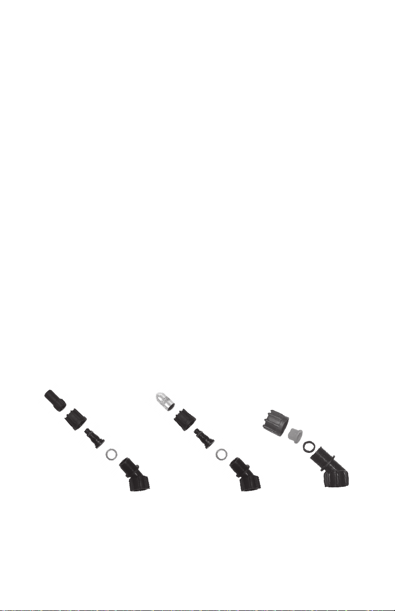
NOZZLE ASSEMBLY
Figure 1-2
Unscrew the nozzle cap (1) from the nozzle body (3) with retaining nut (2) fastened tightly to the elbow
(5). Unscrew the retaining nut (2). Push the nozzle body (3) with the nozzle gasket (4) out of the retain
ing nut (2). To reinstall the nozzle, reverse the above instructions.
Figure 3
Unscrew the retaining nut from the elbow and push the fan nozzle tip and gasket out of the retaining nut.
To reinstall the nozzle, reverse the above instructions.
-
1. Poly
Nozzle Cap
2. Retaining
Nut
4. Nozzle
Gasket
3. Nozzle
Body
5. Elbow
1. Brass
Nozzle Cap
2. Retaining
Nut
4. Nozzle
Gasket
2E
3. Nozzle
Body
5. Elbow
Retaining Nut
Nozzle
Gasket
Fan Nozzle Tip
Elbow
Figure 3Figure 2Figure 1
Page 4
SPRAYER COMPONENTS & USE INFORMATION, Continued
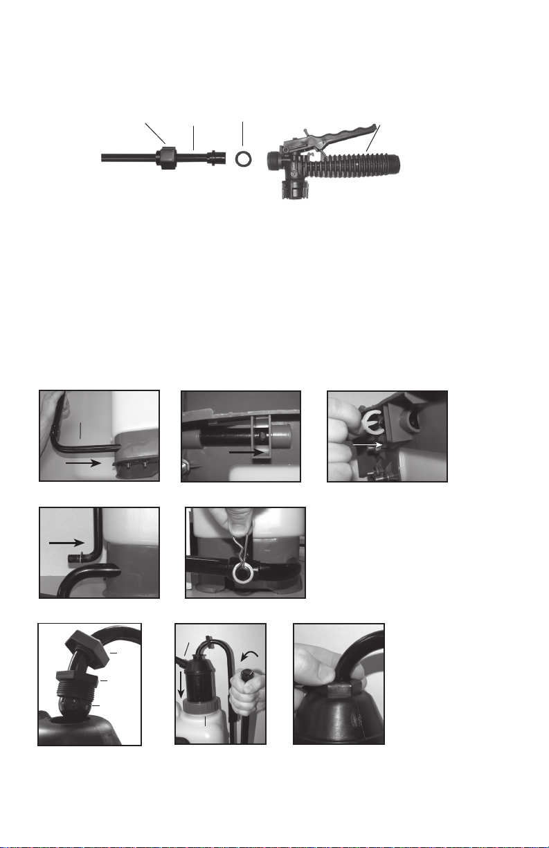
WAND ASSEMBLY
1. Make sure the o-ring is installed on the end of the wand. Insert the wand into shut-off valve.
2. Turn and tighten the retaining nut clock-wise onto the shut-off valve.
Retaining Nut
Wand
O-ring
Shut-off
Valve
INSTALLING THE PUMP HANDLE
The sprayer includes all hardware necessary for installing the pump handle. Install the pump handle
into the base (A). Center the hole in the handle between the cut-out on the bottom of the tank base (B).
Push the “C” clip over the pump handle while aligning the nub on the clip with the hole in the handle
(C). Slide washer over pump linkage (short end) (D). Slide pump arm linkage (short end) through
pump handle at the bottom of the tank (D & E). Slide a second washer over the linkage and insert the
cotter pin through the hole in linkage (E). Position ball over top of pump (F). The pump assembly can
be rotated to orient the pump outlet into desired position (G). Rotate handle down until ball is seated
in top of pump (F and G). Tighten pump retainer nut (F). Do not over tighten. Press boot over retainer
nut (H). Insure pump locking nut is tight (G).
A
Pump
Handle
A B C
“C” Clip
Pump Arm
Linkage
F
D E
Pump
outlet
Boot
Retainer
Nut
Ball
Pump
Locking Nut
G
H
3E
Page 5
SPRAYER COMPONENTS & USE INFORMATION, Continued
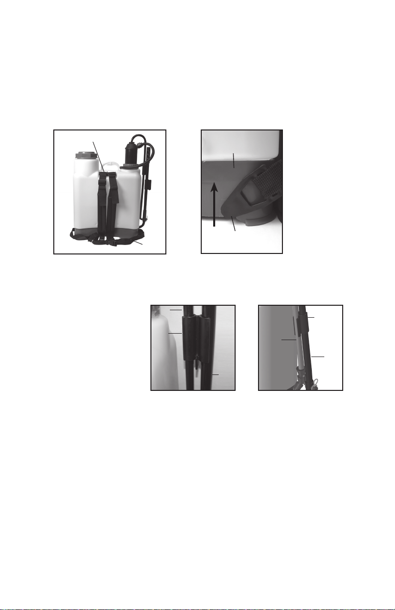
INSTALLING THE SHOULDER STRAP
The backpack strap is provided with multiple features including shoulder strap and waist strap
(figure 1). The top of the shoulder strap is attached to the top of the tank and is removable.
The strap attaches to the base of the sprayer by sliding the buttons into the slots until they snap
into place (Figure 2).
Shoulder
Strap
Tank Base
Strap Button
Figure 2Figure 1
Pump
Handle
Wand
Wand Clip
Pump
Handle
Figure 2Figure 1
Strap Assembly
WAND/PUMP HANDLE
The pump handle stores
vertically and sets into the
pump handle clip (Figure 1).
The wand is stored in the wand
clip (Figure 2).
Waist
Strap
Pump
Handle Clip
Link
Arm
FILLING THE SPRAYER
Make sure the filter basket is in place to keep debris from entering the tank.
Determine the amount of mixture needed for your application. Add the proper amount of water to
the tank. Add the proper amount of chemical to the tank (check the chemical label for proper ratio of
chemical). Stir mixture in tank with a clean utensil (like a paint stirrer). The tank will hold the 5-gallon
(20L) capacity plus the chemical.
It is not necessary to completely fill the sprayer tank with each use. You can fill the tank with only the
amount needed for each application.
Always follow the manufacturer’s instructions included on their product label.
4E
Page 6

SPRAYER COMPONENTS & USE INFORMATION, Continued
HELPFUL SPRAYING INFORMATION
Use RAPID pump strokes to prime the pump. You will know the pressure chamber is filling with liquid
when you feel firm resistance from the pump handle. The air in the pressure chamber is compressed from
repeated strokes. By pressing the hand lever on the shut-off, the valve opens. For safety lock-off feature
(no-spraying), pull up on handle and move red locking mechanism into lock-off position as shown in fig.
1. To disengage, pull up on handle and return red locking mechanism to neutral position as in fig. 3. For
lock-on feature (continuous spraying), push down on handle and move red locking mechanism into lock-
on position as shown in fig. 2. To disengage, push down on handle and return red locking mechanism to
neutral position as shown in fig. 3.
In the event that the handle becomes stuck in the lock-on (continuous spraying) position and the tank
pressure needs to be relieved, carefully open the tank and place the wand inside the tank until the
pressure is relieved.
LOCK-ON POSITION NEUTRAL POSITIONLOCK-OFF POSITION
Locking Mechanism
Handle
Up
Handle
Down
Figure 1 Figure 2 Figure 3
For easy pump action use the END of the pump handle. The amount of liquid delivered during spraying
depends on the rate of pump stroke. The fan nozzle tip is rated at .4 gpm at 40psi. This is the nominal
operating pressure of the sprayer..
POWDER-BASED CHEMICALS
Powder-based chemicals (powder mixed with liquids to
make the spraying agent) are usually abrasive and can
Agitator
Bar
cause wear. When you use a powder-based chemical in
your sprayer, make sure it is thoroughly dissolved in the
liquid solution. Thoroughly clean and flush the sprayer
with water to extend the life of the sprayers parts.
This sprayer is equipped with an agitator bar which facili
-
tates mixing as the pump is operated.
CLEANING
1) Always empty the sprayer and clean the tank thoroughly after each use.
2) Pump the sprayer handle until all of the contents and air exit through the nozzle (minimum of
30 strokes).
3) Fill tank half way with water and pump the water out as explained in step 2 (repeat several times
as necessary).
Other Cleaning Hints:
• Improper spray distribution usually means the nozzle is clogged, remove the nozzle and clean it.
• Soap can be added to the water to clean the tank.
• Do not use strong cleaning agents or abrasives.
• If you use a chemical agent to clean the tank follow the manufacturer’s recommendations for the
disposal of the waste water.
• Follow the chemical manufacturers instructions for clean up.
5E
Page 7

STORING / MAINTAINING YOUR SPRAYER
• The sprayer should be stored out of direct sunlight in a cool dry space.
• Before freezing weather make sure to drain all liquid in the tank, pump, pressure cylinder, hose,
shut-off valve, wand and nozzle, to avoid liquid expansion and cracking in the sprayer components
(See “Cleaning” section). Lock the shut-off valve in the “open” position.
• When service is required call your nearest dealer and always insist on original manufactured
replacement parts.
• Inspect the hose, wand, pump, tank and shut-off valve for wear, damage or leaks on a regular basis
and repair defects promptly.
• Every year prior to spraying remove felt gasket (see Pump Disassembly and Rebuild) and saturate
with a light oil. Oil periodically thru out the season as needed.
TROUBLE SHOOTING YOUR SPRAYER
Symptom Possible Reason Correction
Shut-off leaks Connections loose Tighten connection
Worn or damaged shut-off Rebuild or replace the shut-off valve
Wand assembly leaks Connections loose Tighten connection
Damaged or worn o-ring/gasket Replace o-ring/gasket
Nozzle assembly leaks Connections loose Tighten connection
Damaged or worn o-ring/gasket Replace o-ring/gasket
Hose leaking at shut-off Connection loose Tighten retaining nut
Damaged or worn o-ring/gasket Replace o-ring/gasket
Hose leaking at pump outlet Connection loose Tighten retaining nut
Damaged or worn o-ring/gasket Replace o-ring/gasket
Upward pumping action difficult Inlet openings in bottom of piston Remove piston cylinder and clean openings
cylinder clogged (see section on Piston Cylinder Disassembly
and Rebuild)
Piston cylinder check valve stuck Remove piston cylinder check valve cartridge-
Clean, rebuild or replace (see section on Piston
Cylinder Disassembly and rebuild)
Downward pumping action difficult Pressure chamber check valve stuck Remove piston cylinder check valve cartridge Clean, rebuild or replace (see section on Piston
Cylinder Disassembly and rebuild)
Decline in pump performance (cannot Dirt or debris or wear in one or both Remove both check valves and clean, rebuild
achieve pressure and/or doesn’t hold check valves or replace (see section on Piston Cylinder
pressure) Disassembly and Rebuild and also section
on Pump Disassembly and rebuild)
Piston cylinder inside diameter Remove piston cylinder and check inside
surface worn diameter for wear- replace if necessary (see
section on Piston Cylinder Disassembly
and Rebuild)
Plunger cup worn Remove pump assembly and check plunger
cup for wear-replace if necessary (see section
on Pump Disassembly and Rebuild)
Damaged pressure chamber housing Remove pump assembly and replace
pressure chamber housing (see section on
Pump Disassembly and Rebuild)
Incorrect Assembly of plunger and/or Refer to section on Pump Disassembly and
check valve components Rebuild and Piston Cylinder Disassembly and
Rebuild
6E
Page 8

PUMP DISASSEMBLY AND REBUILD
Agitator
Bar
1) Insure the tank and pressure chamber contents are emptied and pressure
has been released in the pressure chamber. To release pressure in the
pressure chamber activate shut-off valve and release all pressure.
Figure 1
Boot
Pump
Locking
Ring
Pressure
Chamber
Pump Handle Clip
Figure 2
Figure 3
Plunger
Cup
Figure 4
Flat side
Seal
Ball
Retainer
Nut
Ball
Pressure
Chamber
Check
Valve
2) Reach into tank fill opening and remove agitator bar from pressure
chamber body (Figure 1).
3) Disconnect linkage arm from the top of the pump assembly (see section
covering Installing The Pump Handle). (Figure 2).
4) Loosen pump locking ring and remove entire pump assembly from tank
(Figure 3).
Check Valve
Remove check valve cartridge assembly from bottom of pressure chamber
utilizing pump handle clip (clip has flat blade incorporated into end). Place
flat blade into slot in bottom of cartridge and unscrew. Once cartridge has
been removed it can either be replaced as an assembly or rebuilt. To rebuild
disassemble two halves of cartridge and replace seal and/or ball (Figure 4 and
5). The seal mounts inside the larger of the two halves of the cartridge. The
seal counterbore side mounts into the grooves in the cartridge halve. Pump
performance my be affected if this is not assembled correctly.
Plunger Cup
Once the check valve has been removed the plunger cup can be replaced as the
check valve housing holds the plunger cup in place to the bottom of the pressure
chamber body. The bottom of the pressure chamber body has a groove in it to
accept the raised ring on the plunger cup. It is important to insure that these
two surfaces are aligned and mated before tightening the check valve. Pump
performance may be affected if this is not assembled correctly.
Counterbore Side
Figure 5
7E
Page 9

Felt
Washer
Pump
Locking
Ring
Felt
Washer
Figure 6
Figure 7
Gasket
Pressure Chamber Housing Gasket and Felt Washer
Slide both the gasket and felt washer off the pressure chamber body (Figure 6).
Replace felt washer first taking care not to fold over washer as it is worked up
the pump chamber and into the pump locking ring (figure 7). The felt washer is
pre-lubricated to provide lubrication between the pressure chamber housing and
pressure chamber housing gasket. Insure the felt washer is free of contamination
before installing. Replace gasket into the pump opening in the tank insuring
the flanged end is up (if this is assembled backwards leakage will occur) (Figure
8). Insure that the sides of the gasket are inside the tank pump opening and the
flange is sitting level on the tank pump opening seal surface area.
5) Replace pump assembly into tank and into the piston cylinder which is mount-
ed on the bottom of the tank. Be careful not to damage the plunger seal as it seats
into the piston cylinder. It is recommended that you view through the tank fill
opening while performing this to achieve better alignment. If necessary you can
also reach in and use your hand to guide the plunger seal into the piston cylinder.
Pressure Chamber
Housing Gasket
6) Position the pump outlet (hose connection) in the desired position. Tighten
the pump retaining ring onto the tank.
7) Reach into tank fill opening and attach agitator to pressure chamber body.
8) Connect linkage arm to the top of the pump assembly (see section covering
Figure 8
Installing The Pump Handle).
PUMP DISASSEMBLY AND REBUILD
Agitator
Bar
1) Insure the tank and pressure chamber contents are emptied and pressure
has been released in the pressure chamber. To release pressure in the pressure
chamber activate shut-off valve and release all pressure.
Figure 1
Boot
Retainer
Nut
Ball
2) Reach into tank fill opening and remove agitator bar from pressure chamber
body (Figure 1).
3) Disconnect linkage arm from the top of the pump assembly (see section
covering Installing The Pump Handle). (Figure2).
Figure 2
Pressure
Chamber
Pump
Locking
Ring
4) Loosen pump locking ring and remove entire pump assembly from
tank ( Figure 3).
Figure 3
8E
Page 10
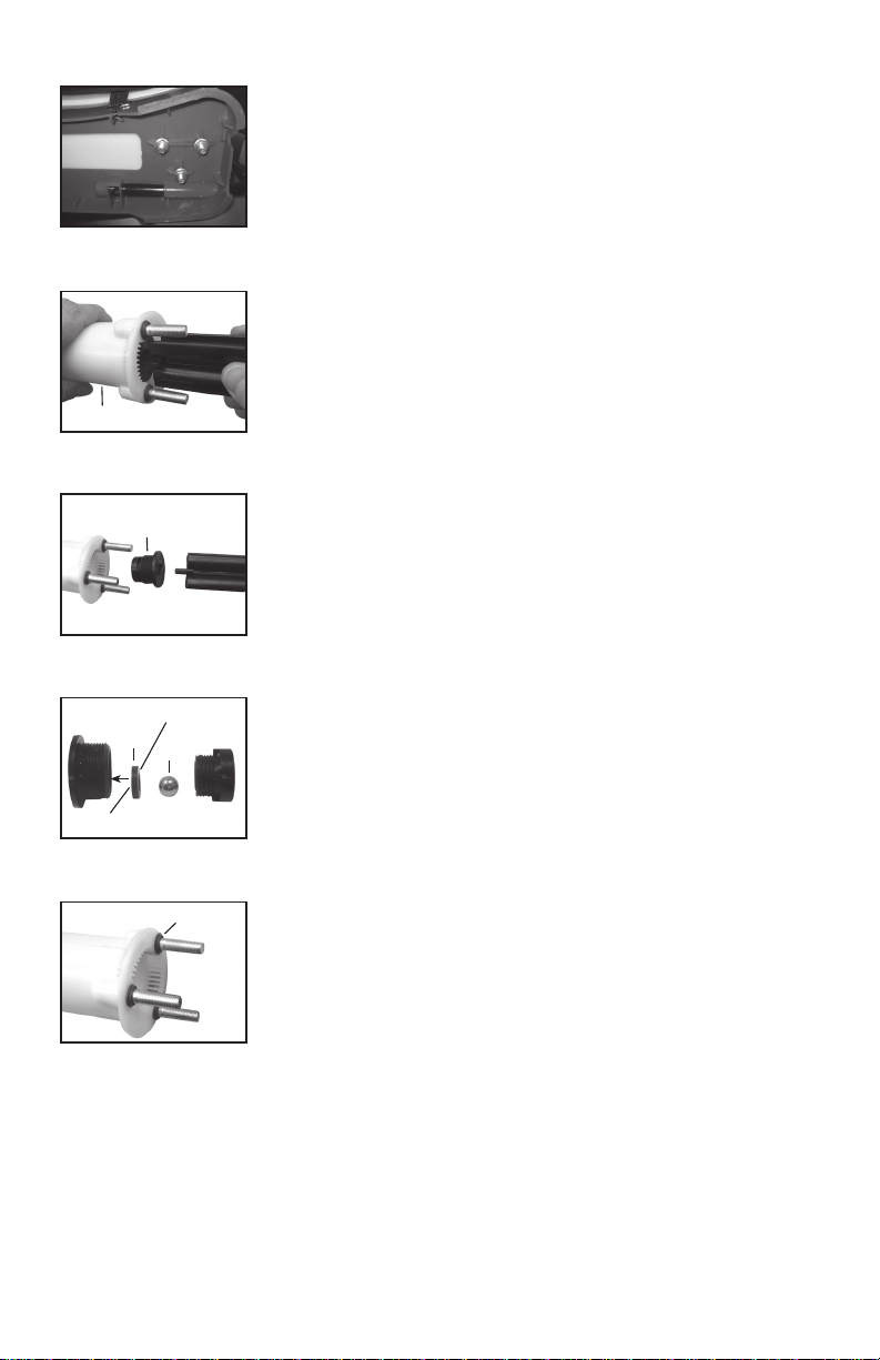
Figure 4
5) Remove the three bolts attaching the piston cylinder to the bottom of
the tank (Figure 4).
6) Reach in through the tank fill opening and remove the piston cylinder.
7) Remove check valve cartridge assembly from bottom of piston cylinder
utilizing pump handle clip (clip has flat blade incorporated into end). Place
flat blade into slot in bottom of cartridge and unscrew (Figure 5 and 6).
Piston Cylinder
Figure 5
Check Valve
Figure 6
Seal
Counterbore Side
Figure 7
Figure 8
Flat side
Ball
Stud Gaskets
8) Once cartridge has been removed it can either be replaced as an
assembly or rebuilt.
9) To rebuild disassemble two halves of cartridge and replace seal and/
or ball. Replace cartridge (Figure 7). The seal mounts inside the larger of
the two halves of the cartridge. The seal counterbore side mounts into the
grooves in the cartridge halve. Pump performance my be affected if this is
not assembled correctly.
10) At this point the piston cylinder itself and/or piston cylinder stud
gaskets can be replaced. The piston cylinder stud gaskets must be oriented
correctly or leakage may result (Figure 8).
11) Reassemble piston cylinder using washers and bolts on the underside of
the base.
12) Replace pump assembly into tank and into the piston cylinder which is
mounted on the bottom of the tank (see important notes regarding gasket
and felt washer in Pump and Disassembly and Rebuild section). Be careful
not to damage the plunger seal as it seats into the piston cylinder. It is
recommended that you look through the tank fill opening while performing
this to achieve better alignment. If necessary you can also reach in and use
your hand to guide the plunger seal into the piston cylinder.
13) Position the pump outlet (hose connection) in the desired position.
Tighten the pump retaining ring onto the tank.
14) Reach into tank fill opening and attach agitator to pressure chamber
body.
15) Connect linkage arm to the top of the pump assembly (see section
covering Installing the Pump Handle)
9E
Page 11

DISASSEMBLING AND REPAIRING THE SHUT OFF VALVE
1) Assembled shut-off valve (Figure 1).
Figure 1
2) Remove the retaining pin (A) (Figure 2) place the notched end
of the retaining pin on a hard surface and push down. Remove the
retaining pin and slide the handle off the valve.
A
Figure 2
Valve
Stem
3) Remove the retaining nut (o-ring attached), spring, and valve stem (B)
(Figure 3). Replace worn parts. Lubricate the O-rings and reassemble by
reversing the steps above. Place the handle groove in the slotted area of
B
the valve stem and make sure the locking clip is positioned in the neutral
position (see “Helpful Spraying Information” section). Insert the retaining
pin. Push down on the handle a few times to distribute the lubricant
C
evenly. Check filter (C) in end of shut-off valve for debris. Remove filter
and flush with water to clean out.
Figure 3
REPLACEMENT PARTS ORDER INFORMATION
569012
Flat Fan Nozzle
569011
Poly
Adjustable
Nozzle
569010
Brass
Adjustable
Nozzle
569013
Nozzle kit
10E
Page 12
O-ring
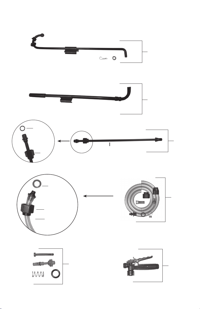
REPLACEMENT PARTS ORDER INFORMATION
Screw
Cap
Wand
569019
Link Arm Assembly
569026
Pump Handle w/clip
99944100480
Wand
Assembly
Hose Washer
Retaining Nut
Hose
99944100477
Shut-off Valve
Repair Kit
11E
99944100479
Hose
Assembly
99944100478
Shut-off
Assembly
Page 13

REPLACEMENT PARTS ORDER INFORMATION
569024
Piston Cylinder Kit
569028
Pressure Chamber Housing
569020
O-ring kit
569021
Pump Seal Kit
569023
Valve cartridge kit
99944100472
Straps
569002
Filter Basket & Cap
Page 14

MS-53BPE MSP10000001 - MS-53BPE MSP99999999
 Loading...