

Page 1

Backpack
Use and Care
Manual
Model MS-40BD
4.0G/15.1L
WARNING!
Carefully Read These Instructions Before Use
011300 R0211
Page 2

WARNING!
IMPROPER USE OR FAILURE TO FOLLOW INSTRUCTIONS CAN RESULT IN
PRODUCT FAILURE OR INJURIES. FOR SAFE USE OF THIS PRODUCT YOU MUST
READ AND FOLLOW ALL INSTRUCTIONS BEFORE USING.
WARNING: Handling the brass parts of this product will expose you to lead, a chemical
known to the State of California to cause birth defects and other reproductive harm.
Wash hands after handling.
CAUTION
RULES FOR SAFE OPERATION
Before assembling and operating your sprayer, read all instructions
thoroughly. When working with equipment under pressure, safety
precautions must always be carefully observed, including the following:
• NEVER spray flammable materials or pressure and gas producing
chemicals.
•
ALWAYS read chemical label before filling sprayer as some chemicals may
be hazardous when used with this sprayer.
• ALWAYS wear goggles, gloves, a long-sleeve shirt, long pants, and full foot
protection when spraying. Work in a ventilated area or outdoors.
• PRE-USE CHECK: Before each use check tightness of hose nut to be sure hose is
securely attached to the shut-off assembly. Insure hose is securely attached to the tank
by tightening hose clamp if necessary. Insure that all nozzle and wand connections are
tight. Insure the large pump clamp is tight. Insure the 2 bolts used to attach the pump
lever to the pump shaft are tight.
• DO NOT leave a pressurized sprayer in the hot sun or anywhere near a heat source.
Heat can produce pressure to build up causing sprayer to ignite or explode resulting in
injury or death.
• NEVER pressurize sprayer by any means other than the original pump. Over
pressurizing can cause sprayer to explode resulting in injury or death.
• DO NOT attempt to modify or repair this product except with original manufacturer’s
parts.
NOTE: The tank and hose may have residual water in it due to quality
testing performed on the sprayer.
1E
Page 3

APPLICATIONS & USE FOR YOUR SPRAYER
Avoid using a sprayer for general cleaning purposes if plant protection or herbicide chemicals
have already been used in the sprayer. If a sprayer has been used for plant protection or as an
herbicide, clean the sprayer completely (see cleaning section) before using.
Plant Food
: Use different spray patterns for optimum foliage feeding or for fungicide and
pesticide application.
Herbicides: Reduce weeds and unwanted plants but avoid using the same sprayer for plant
feeding or protection without thoroughly cleaning (see cleaning section) the sprayer first.
General Household Use: Apply detergents, vinegar, cleaning solutions, warm water (do not
exceed 120°F/49°C) or nontoxic household cleaning chemicals for carpets, floors, walls, glass,
counter tops and ceilings. DO NOT use sprayer that has been used with herbicides, pesticides or
other toxic chemicals for household applications.
General Outdoor Use: Use the sprayer for cleaning windows or with a detergent for general
purpose cleaning. Other applications include wood preservatives, waxes, water proofing, and
diluted household bleach (max. 1 part household bleach to 9 parts water solution).
SPRAYER COMPONENTS & USE INFORMATION
NOZZLE ASSEMBLY
Figure 1-2
Unscrew the nozzle cap (1) from the nozzle body (3) with retaining nut (2) fastened tightly to
the elbow (5). Unscrew the retaining nut (2). Push the nozzle body (3) with the nozzle gasket
(4) out of the retaining nut (2). To reinstall the nozzle, reverse the above instructions.
Figure 3
Unscrew the retaining nut from the elbow and push the fan nozzle tip and gasket out of the retaining
nut. To reinstall the nozzle, reverse the above instructions.
1. P
oly
Nozzle Ca
p
2. Retaining
Nut
3. Nozzle
Body
1. Brass
Nozzle Cap
2. Retaining
Nut
3. Nozzle
Body
Retaining Nut
Fan Nozzle Tip
4. Nozzle
Gasket
5. Elbow
4. Nozzle
Gasket
5. Elbow
Figure 1 Figure 2 Figure 3
WAND ASSEMBLY
1. Make sure the o-ring is installed on the end of the wand.
Insert the wand into shut-of f valve.
2. Turn and tighten the retaining nut clock-wise onto the shut-off valve.
Wand
Retaining Nut
O-ring
2E
Shut-off
Valve
Nozzle
Gasket
Elbow
Page 4
SPRAYER COMPONENTS & USE INFORMATION, Continued
INSTALLING THE PUMP HANDLE
The pump handle can be mounted on either side of the pump
shaft (A).
To install the pump handle place the handle (C) over
the shaft (A) aligning the pump handle hole and shaft hole. Push
the straight side of the cotter pin (B) through the aligned hole as
shown in figure 1 thru 3. There are holes in the pump handle to
allow for either left(fig.4) or right (fig.5) hand mounting.
C
A
B
Figure 1
Cotter Pin
Figure 4
Left Hand
Figure 2
Line up holes
Figure 5
Right Hand
STOWAWAY PUMP HANDLE
Pull
up
INSTALLING THE
SHOULDER STRAP
The top of the shoulder
straps are attached to
the tank.
Attach the
lower end of the straps
by clipping the strap
hooks to the metal
frame between where
the frame exits the tank
and curves around.
Rotate
180º
Figure 3
Slide pin through holes.
Pump Handle
Positioned For Use
(right hand shown)
Set
into
slot
WAND CLIP
The wand can be
attached to the
pump handle using
the wand clip.
3E
Page 5

SPRAYER COMPONENTS & USE INFORMATION, Continued
4 STAGE FILTERING SYSTEM
This backpack sprayer is equipped with a 4 stage filtering system (see figure 1).
Stage 1 is a filter basket incorporated into the tank opening where fluid is
added. Stage 2 and 3 filters are located at the inlet of the pressure cylinder.
Stage 2 is a removable In-Tank filter. Stage 3 is a removable filter cartridge
integrated into the pressure cylinder. Stage 4 is a removable filter incorporated
into the shut-off assembly. Periodic cleaning of these filters is recommended to
insure consistent fluid flow through the sprayer. This will also reduce sprayer
component wear.
Stage 3 filter cartridge cleaning requires removal of the entire pressure cylinder
assembly (see section “disassembling and repairing the pressure cylinder”).
Once the pressure cylinder is removed the stage 3 filter can be removed for
cleaning (see figure 3). Periodic cleaning of the stage 2 filter is highly
recommended and will reduce the need to perform this disassembly. It is best
to have no or minimal fluid in the tank before removing and reinstalling the
stage 2 In-Tank filter. The In-Tank filter needs to be oriented in a specific way
when inserted into the pressure cylinder base (see figure 2).
The stage 4 filter is a removable filter incorporated into the inlet side of the
shut-off valve (see section “disassembling and repairing the shut-off valve”) .
Make sure pressure is released before detaching the hose from the shut-off. It
is best to have no or minimal fluid in the pressure cylinder before removing
and reinstalling the stage 4 shut-off filter as fluid can leak from the hose.
Figure 1
Stage 2
(removable
In-Tank filter)
Stage 1
(filter
basket)
Pressure
Cylinder
Stage 3 (removable
filter cartridge)
Stage 4
(Removable
Shut-off filter)
Figure 2 Stage 2 (removable In-Tank filter)
Guide edge facing away
from pressure cylinder
Guide edge on
pressure cylinder
Figure 3 Stage 3 (removable filter cartridge)
pressure cylinder base
Filter cartridge removedFilter cartridge in
FILLING THE SPRAYER
Make sure the filter basket is in place to keep debris from entering the tank.
Determine the amount of mixture needed for your application. Add the proper amount of water to the
tank. Add the proper amount of chemical to the tank (check the chemical label for proper ratio of
chemical). Stir mixture in tank with a clean utensil (like a paint stirrer). The tank will hold the 4-gallon
(15.1L) capacity plus the chemical.
It is not necessary to completely fill the sprayer tank with each use. You can fill the tank with only the
amount needed for each application.
Always follow the manufacturer’s instructions included on their product label.
4E7F
Page 6

SPRAYER COMPONENTS & USE INFORMATION, Continued
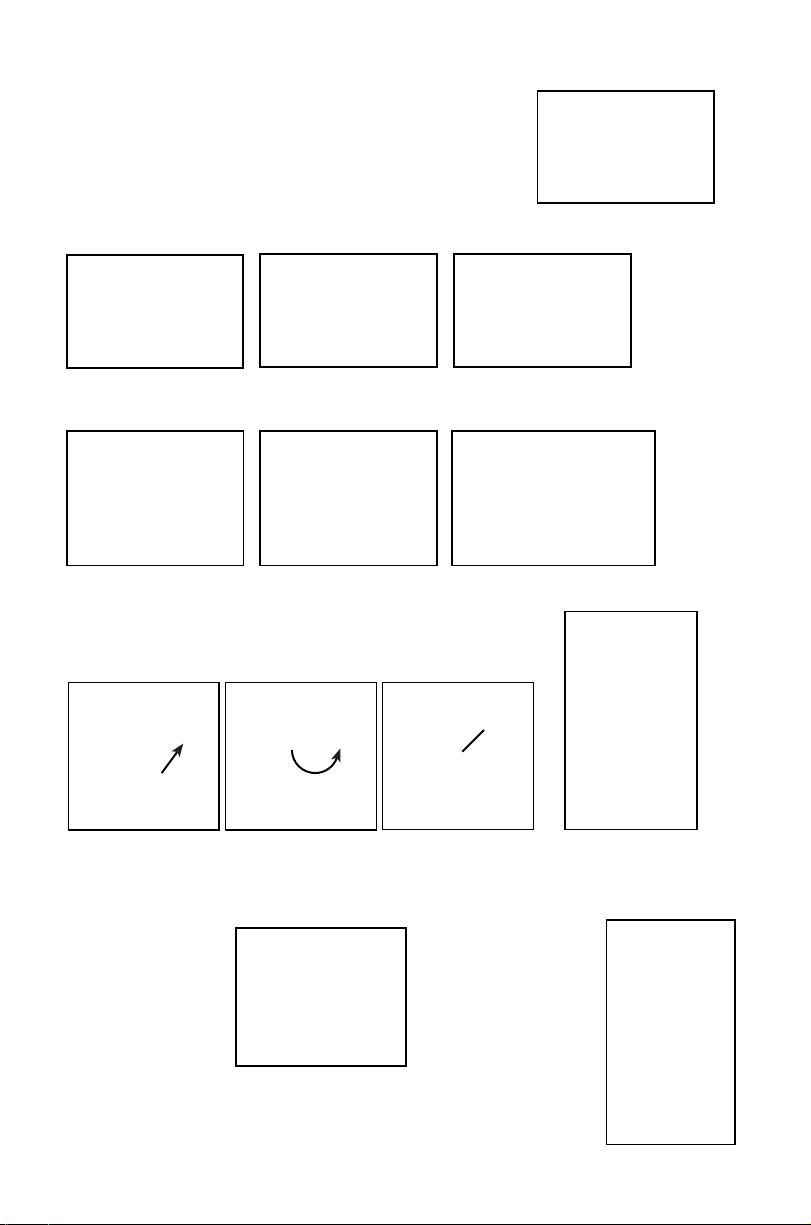
HELPFUL SPRAYING INFORMATION
Use RAPID pump strokes to prime the pump.
You will know the pressure chamber is filling with liquid
when you feel firm resistance from the pump. The air in the pressure chamber is compressed from
repeated strokes. By pressing the hand lever on the shut-off, the valve opens. For safety lock-off feature
(no-spraying), pull up on handle and move red locking mechanism into lock-off position as shown in fig.
1. To disengage, push down on handle and return red locking mechanism to neutral position as in fig. 3.
For lock-on feature (continuous spraying), push down on handle and move red locking mechanism into
lock-on position as shown in fig. 2. To disengage, push down on handle and return red locking
mechanism to neutral position as shown in fig. 3.
LOCK-OFF POSITION LOCK-ON POSITION NEUTRAL POSITION
Locking Mechanism
Handle
Up
Handle
Down
Figure 1 Figure 2 Figure 3
For easy pump action use the END of the pump handle. The amount of liquid delivered during spraying
depends on the rate of pump stroke. The fan nozzle tip is rated at .4 gpm at 40psi. This is the nominal
operating pressure of the sprayer.
Note:
If you experience a rapid drop in pressure, drain the sprayer completely and pump the handle
with an empty tank. The pressure chamber will fill with the required volume of air to repressurize.
Chapin advises performing this procedure from time to time as routine maintenance.
POWDER-BASED CHEMICALS
Powder
-based chemicals (powder mixed with liquids to make the spraying agent) are usually abrasive
and can cause wear. When you use a powder-based chemical in your sprayer, make sure it is thoroughly
dissolved in the liquid solution. Thoroughly clean and flush the sprayer with water to extend the life of
the sprayers parts.
CLEANING
1) Always empty the sprayer and clean the tank thoroughly after each use.
2) Pump the sprayer handle until all of the contents and air exit through the nozzle (minimum of 30
strokes).
3) Fill tank half way with water and pump the water out as explained in step 2 (repeat several times as
necessary).
Other Cleaning Hints:
• Improper spray distribution usually means the nozzle is clogged, remove the nozzle and clean it.
• Soap can be added to the water to clean the tank.
• Do not use strong cleaning agents or abrasives.
• If you use a chemical agent to clean the tank follow the manufacturer’s recommendations for the
disposal of the waste water.
• Follow the chemical manufacturers instructions for clean up.
5E
Page 7

STORING / MAINTAINING YOUR SPRAYER
• The sprayer should be stored out of direct sunlight in a cool dry space.
• Before freezing weather make sure to drain all liquid in the tank
, pump, pressure cylinder, hose,
shut-off valve, wand and nozzle, to avoid liquid expansion and cracking in the sprayer components
(See “Cleaning” section). Lock the shut-off valve in the “open” position.
• When service is required call your nearest dealer and always insist on original manufactured
replacement parts.
• Inspect the hose, wand, pump, tank and shut-off valve for wear, damage or leaks on a regular basis
and repair defects promptly.
TROUBLE SHOOTING YOUR SPRAYER
Symptom
Possible Reason Correction
Difficulty actuating the pump handle and/or Upper valve plate sticks Clean or replace valve pla
pump handle moves itself back up.
Little or no resistance during Damaged/worn/dirty/upper valve plate Clean or Replace Valve Plate
repeated pumping – no pressure. Damaged /worn upper o-ring on piston cylinder Replace O-ring
Diaphragm pump is damaged Replace Diaphragm pump
Too much resistance after just a few Not enough air cushion in the pressure Release pressure in pressure chamber
pumping strokes but pressure only lasts chamber Remove the hose & drain pressure
briefly. chamber. Reconnect the hose.
Upper valve plate damaged/worn/dirty Clean or replace upper valve plate
Upward pumping action is more difficult Vent hole is clogged Clear the vent hole in cap
and/or pump handle moves itself back down. Clogged intake filter Clean the In-Tank filter and or removable
cartridge filter
Piston cylinder intake clogged Clean piston cylinder intake
Leaks at Diaphragm Pump Damaged/worn/O-rings Replace o-rings on Diaphragm Pump
Damaged Diaphragm Pump Replace Diaphragm Pump
Shut-off leaks Connections loose Tighten connection
Worn or damaged shut-off Rebuild or replace the shut-off valve
Wand assembly leaks Connections loose Tighten connection
Damaged or worn o-ring/gasket Replace o-ring/gasket
Nozzle assembly leaks Connections loose Tighten connection
Damaged or worn o-ring/gasket Replace o-ring/gasket
Leak between pump assembly Pump clamp loose Tighten clamp
and tank O-ring worn or damaged Replace pressure chamber oring
Hose leaking at tank outlet Hose clamp loose Tighten clamp
te
Hose leaking at shut-off Connection loose Tighten retaining nut
Damaged or worn o-ring/gasket Replace o-ring/gasket
6E
Page 8

DISASSEMBLING AND REPLACING THE DIAPHRAGM PUMP
1) De-pressurize the cylinder and remove all liquid from both the pressure
cylinder and tank.
2) Remove the 2 screws attaching the pivot lever to the pump shaft
(fig. 1)
Figure 1
3) Remove cotter pin from pump shaft and remove washer (fig. 2a). Pull and slide the shaft from
opposite side, moving it out of the way of the diaphragm pump assembly (fig. 2b & 2c).
Figure 2a
4) Unscrew diaphragm pump from pressure cylinder base. The use of a strap wrench or other
mechanical means may be neccesary (fig. 3).
Figure 2b
Figure 2c
Figure 3
5) Remove cotter pin from diaphragm pump assembly pivot lever connection. Remove pivot lever and
connection hardware from diaphragm pump assembly (Fig. 4a & 4b).
Figure 4a
Pivot Lever
Connection
Figure 4b
6) Discard Diaphragm Pump Assembly.
7E
Page 9

7) Attach pivot lever and connection hardware to new diaphragm pump
assembly. Make sure orientation is correct with slot in diaphragm cover
( Fig. 5).
8) Apply Petroleum jelly to 2 diaphragm pump o-rings (Fig. 6a).
Thread diaphragm pump assembly into pressure chamber base,
making sure the o-ring seats inside the pressure chamber base
(Fig. 6b-6c). Align the diaphragm pump alignment mark with the
pressure cylinder base alignment mark (fig.6d).
Figure 5
Diaphragm
Cover Slot
The slot in the diaphragm cover will also be in alignment.
O-ring
O-rings
Figure 6a
9) Re-assemble pump shaft (see step 3).
10) Re-attach pivot lever to pump shaft (see step 2).
DISASSEMBLING AND REPAIRING THE PUMP ASSEMBLY
Only remove the pressure cylinder if the cartridge filter is clogged or the sprayer is
leaking fr
1. Release the pressure from the sprayer and remove all liquid from both the pressure cylinder and tank.
2. Remove Hose
3. Remove the In-tank Filter from the pressure cylinder (located inside tank fig 1).
4. Remove the large clamp holding the pressure cylinder and tank together (fig 1).
5. Rock the pressure cylinder back and forth and push down forcefully to free it from the tank (fig 1).
6. Once freed the entire assembly can be removed by angling and maneuvering it through the base frame
(fig 3a & 3b).
om where the pressure cylinder o-ring and tank meet.
Figure 6b
Pressure
Cylinder Base
Figure 6c
Diaphragm Pump
Alignment Mark
Pressure Cylinder Base
Alignment Mark
Figure 6d
Diaphragm
Cover Slot
In-tank Filter
Figure 1
Clamp
Figure 2
Pressure
Cylinder o-ring
Figure 3a Figure 3b
8E
Page 10

7. At this point the filter cartridge in the pressure chamber base can be
removed with pliers and cleaned (fig 4).
8. The pressure chamber o-ring can also be replaced. DO NOT stretch the
Figure 4
o-ring over the bottom flange. Assemble the o-ring over the top of the
chamber. Apply petroleum jelly to the o-ring before reinstalling pump
asembly into the tank (fig. 3b).
9. Reassemble backwards from step 6 thru 2, performing each step in
Tank tab
Figure 5
reverse. Note: there is a notch/tab combination in the pump
assembly/tank to be used for alignment (fig. 5).
Pump Assembly
Notch
DISASSEMBLING AND REPAIRING THE SHUT OFF VALVE
1) Assembled shut-off valve (Figure 1).
Figure 1
A
Figure 2
Figure 3
Valve
Stem
C
2) Remove the retaining pin (A) (Figure 2) place the notched
end of the retaining pin on a hard surface and push down.
Remove the retaining pin and slide the handle o
f the valve
f
stem.
3) Remove the retaining nut (o-ring attached), spring, and valve
stem (B) (Figure 3). Replace worn parts. Lubricate the O-rings and
reassemble by reversing the steps above. Place the
handle groove
in the slotted area of the valve stem and make sure the locking clip
B
is positioned in the neutral position (see “Helpful Spraying
Information” section). Insert the retaining pin. Push down on the
handle a few times to distribute the lubricant evenly. Check filter
(C) in end of shut-off valve for debris. Remove filter and flush
with water to clean out.
9E
Page 11

NOZZLE ASSEMBLY
REPLACEMENT PARTS ORDER INFORMATION
O-ring
Screw
p
Ca
99944100484
Flat Fan
Nozzle
Hose Washer
99944100485
Nozzle Kit
99944100482
Brass
Adjustable
Nozzle
Wand
99944100483
Poly
Adjustable
Nozzle
99944100481
Filter
Replacement Kit
99944100480
Wand
Assembly
Retaining Nut
Hose
99944100477
Shut-off Valve
Repair Kit
10E
99944100479
Hose
Assembly
99944100478
Shut-off
Assembly
Page 12

REPLACEMENT PARTS ORDER INFORMATION
99944100476
Diaphragm Pump
Assembly
Plate Valve
99944100473
Filter Basket &
Cap
O-ring
O-ring
Elbow O-ring Hose Gasket
Nozzle Gasket
Wand O-ring
99944100488
Wand Clip
99944100489
Pump Handle
99944100486
O-ring Kit
99944100472
Straps
ECHO, INCORPORATED
400 Oakwood Road, Lake Zurich, IL 60047
www.echo-usa.com
Page 13

ECHO LIMITED WARRANTY STATEMENT FOR
SPRAYERS SOLD IN USA AND CANADA BEGINNING 01/01/2010
ECHO'S RESPONSIBILITY
ECHO Incorporated’s Limited Warranty, provides to the original end user purchaser that this ECHO product is free from defects
in material and workmanship. Under normal use and maintenance from date of purchase, ECHO agrees to repair or replace
at ECHO’s discretion, any defective product free of charge at any authorized ECHO servicing dealer within listed below
application time periods, limitations and exclusions. THIS LIMITED WARRANTY IS ONLY APPLICABLE TO ECHO PRODUCTS
SOLD BY AUTHORIZED ECHO DEALERS. IT IS EXTENDED TO THE ORIGINAL END USER PURCHASER ONLY, AND
IS NOT TRANSFERABLE TO SUBSEQUENT OWNERS. Repair parts and accessories replaced under this warranty are
warranted only for the balance of the original unit or accessory warranty period. Any damage caused by improper use,
modifications, installation or maintenance is not covered by this warranty. All parts or products replaced under warranty become
the property of ECHO, Inc. For a list of Authorized ECHO Dealers refer to WWW.ECHO-USA.COM or call 1-800-432-Echo.
OWNER’S RESPONSIBILITY
To ensure trouble free warranty coverage it is important that you register your Echo equipment on-line at WWW.ECHOUSA.COM or by filling out the warranty registration card supplied with your unit. Registering your product confirms your warranty
coverage and provides a direct link if we find it necessary to contact you. The owner shall demonstrate reasonable care and
use, and follow preventative maintenance and storage Instructions, as prescribed in the Use & Care Manual. Should a product
difficulty occur, you must, at your expense, deliver or ship your ECHO unit to an authorized ECHO servicing dealer for warranty
repairs (within the applicable warranty period), and arrange for pick-up or return of your unit after the repairs have been made.
For your nearest authorized ECHO servicing dealer, call ECHO’s Dealer Referral Center, at 1-800-432-ECHO or you can locate
an ECHO servicing dealer at WWW.ECHO-USA.COM. Should you require assistance or have questions concerning ECHO’s
Warranty Statement, you can contact our Consumer Product Support Department at 1-800-432-ECHO or contact us through
the web at WWW.ECHO-USA.COM.
PRODUCT WARRANTY PERIOD
RESIDENTIAL APPLICATION
• 5 YEAR WARRANTY - All units for residential, or non-income producing use will be covered by this limited warranty for five
(5) years from date of purchase.
EXCEPTIONS:
• Damage caused by:
Failure to follow Use & Care Manual
• Failure to follow all chemical manufacturers’ instructions included on their label or elsewhere
• Failure to follow Storing/Maintaining Your Sprayer section in Use & Care manual
Use of powder based chemicals with or in a piston pump sprayer
Wear items including but not limited to: seals, gaskets, pistons, hoses, diaphragms, straps or any wear item. These items are
covered for 90 days from date of purchase.
Any mis-use of product is not covered including but not limited to: using un-approved chemicals or parts, un-approved uses,
using damaged or missing units/parts during operation, or modifying your sprayer in any manner.
COMMERCIAL APPLICATION
• 2 YEAR WARRANTY - All units for commercial, institutional, agricultural, industrial, or income producing use will be covered
by this limited warranty for two (2) years from the date of purchase.
EXCEPTIONS:
• Failure to read and follow Use & Care Manual
• Failure to follow all chemical manufacturers’ instructions included on their label or elsewhere
• Failure to follow Storing/Maintaining Your Sprayer section in Use & Care Manual
Use of powder based chemicals with or in a piston pump sprayer
Wear items including but not limited to: seals, gaskets, pistons, hoses, diaphragms, straps or any wear item. These items are
covered for 30 days from date of purchase.
Any mis-use of product is not covered including but not limited to: using un-approved chemicals or parts, un-approved uses,
using damaged or missing units/parts during operation, or modifying your sprayer in any manner.
RENTAL APPLICATION - 90 DAYS WARRANTY
• Units for rental use will be covered against defects in material and workmanship for a period of 90 days from the date of
purchase except for any of the above listed EXCEPTIONS.
PURCHASED REPAIR PARTS AND ACCESSORIES
90-day residential or non-income producing warranty except for any one of the above listed EXCEPTIONS
• 30-day commercial, institutional, agricultural, industrial, income producing, or rental application warranty except for any one
of the above listed EXCEPTIONS
YOUR RECEIPT OF PURCHASE INCLUDING DATE, MODEL AND SERIAL NUMBER MUST BE MAINTAINED AND
PRESENTED TO AN AUTHORIZED ECHO SERVICING DEALER FOR WARRANTY SERVICE. PROOF OF PURCHASE
RESTS SOLELY WITH THE CUSTOMER. SOME STATES DO NOT ALLOW LIMITATIONS ON HOW LONG AN IMPLIED
WARRANTY LASTS, SO THE ABOVE LIMITATIONS MAY NOT APPLY TO YOU. SOME STATES DO NOT ALLOW THE
EXCLUSION OR LIMITATION OF INCIDENTAL OR CONSEQUENTIAL DAMAGES, SO YOU MAY ALSO HAVE OTHER
SPECIFIC LEGAL RIGHTS WHICH VARY FROM STATE TO STATE. THIS LIMITED WARRANTY IS GIVEN BY ECHO
INCORPORATED, 400 OAKWOOD RD., LAKE ZURICH, IL 60047.
DISCLAIMER OF IMPLIED WARRANTIES
THIS LIMITED WARRANTY IS IN LIEU OF ALL OTHER EXPRESSED OR IMPLIED WARRANTIES, INCLUDING ANY
WARRANTY OF FITNESS FOR A PARTICULAR PURPOSE OR USE AND ANY IMPLIED WARRANTY OF MERCHANTABILITY
OTHERWISE APPLICABLE TO THIS PRODUCT. ECHO AND ITS AFFILIATED COMPANIES SHALL NOT BE LIABLE FOR
ANY SPECIAL INCIDENTAL OR CONSEQUENTIAL DAMAGE, INCLUDING LOST PROFITS. THERE ARE NO WARRANTIES
EXTENDED OTHER THAN AS PROVIDED HEREIN. THIS LIMITED WARRANTY MAY BE MODIFIED ONLY BY ECHO.
 Loading...