

Page 1

Echo® MegaLoop Pro™
Product Code: 901-1010-02
User Manual
Hearing Products International Limited.
Page 2

2
CONTENT
Introduction
2 Content / Introduction
3 Safety Instructions and Precautions
4 Contents Picture
5 Set Up
6 Set Up
7 Connection
8 Connection
9 Power
10 Additional Information
11 Additional Information
12 Remote
13 Replacement Parts
14 Technical Specifications
15 Conformity
The Echo® MegaLoop Pro
TM
Induction loop amplifier provides a
practical solution for listening to TV or Audio equipment via the
‘T’ setting or hearing loop on your hearing aid.
The induction loop system takes sound from your TV or other
sound source and amplifies this sound signal around a wire fitted
in a continuous loop around the edges of the room. This signal is
sent out in the form of an alternating current and when the
alternating current flows through the loop a magnetic field is
created within the room. The hearing aid user picks up the
fluctuations in the magnetic field and converts them into sound
via the amplifier and this provides an improved sound signal.
Page 3

3
1. Listening to uncomfortable sound levels for prolonged periods
could adversely affect your hearing.
2. Using this product inappropriately could adversely affect your
hearing. Please follow the step-by-step instructions carefully!
3. To clean the MegaLoop Pro™ and its accessories, use only a soft
cloth and an inorganic cleaner.
4. Only use the Hearing Products approved mains adapter. Do not
use any other type of mains adapter.
5. When using this unit, basic safety precautions should always be
followed to avoid the risk of electrical shock or personal injury.
6. Read and understand the instructions and follow all warnings
and markings on the unit.
7. Do not use in an environment that is damp, wet, very hot or
very cold.
8. Install the unit securely on a stable surface and install the unit
where the power cord will not be subject to damage or cause a
tripping hazard.
9. The unit may get warm when being used. Ensure the unit has
adequate ventilation.
10. Please refer all servicing to qualified personnel ONLY! Note: if
the serial number is removed your warranty is invalid.
Safety Instructions
The manufacturer cannot be held responsible for damage
which is caused by not using this Loop System in compliance
with these safety instructions:
Page 4

Contents Picture
A. MegaLoop Pro Amplifier with Stand
B. Mains Power Adapter
C. Loop Wire
D. Clips
E. Microphone
F. SCART Plug
G. Phono Phono Lead
H. TOSlink Cable
I. Remote Control
J. AAA Drycell (2)
A
B C D
E F G
H I J
4
Page 5
5
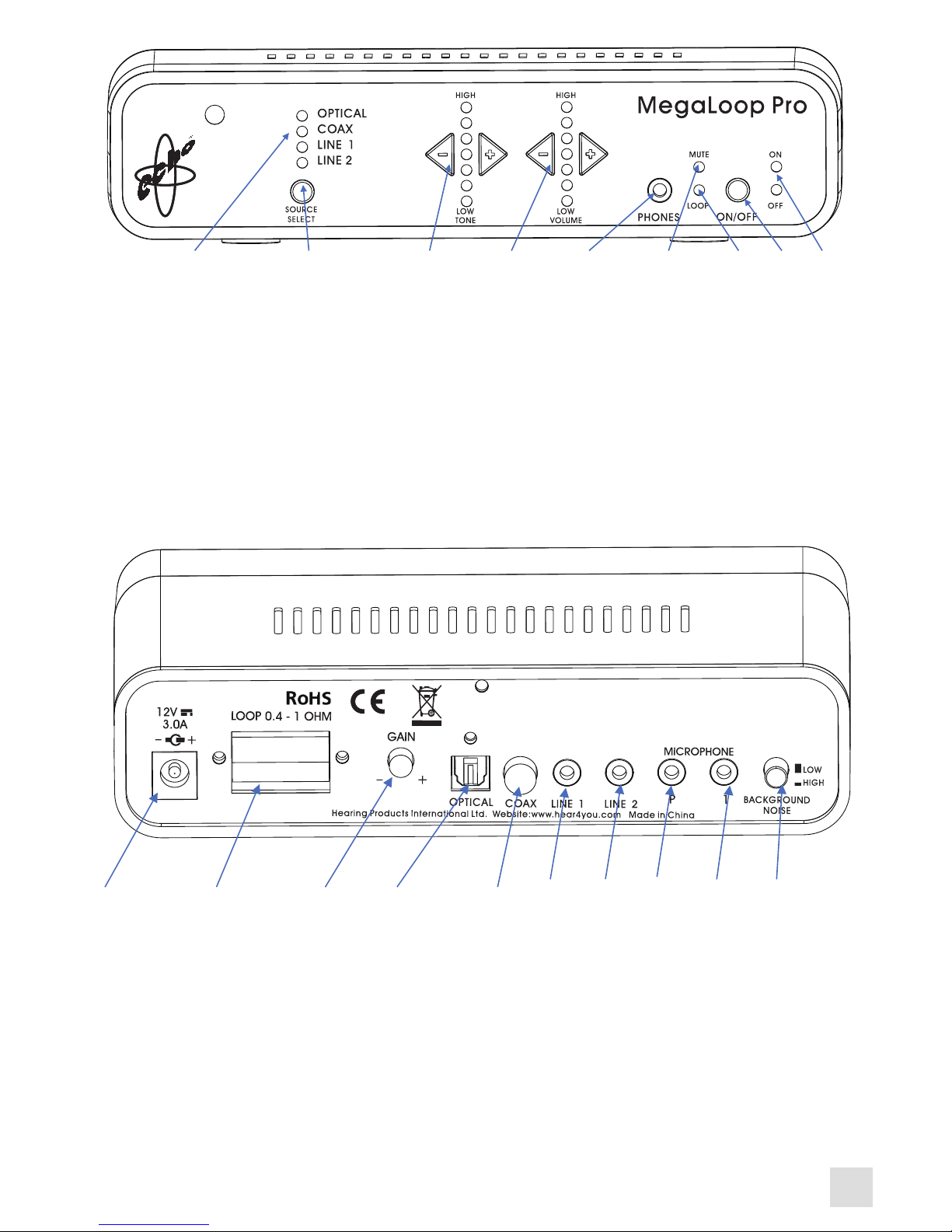
11. DC Power Socket
12. Loop Cable Connectors
13. Gain Control
14. Optical Digital Audio Input
15. Coaxial Digital Audio Input
16. Line Input 1
17. Line Input 2
18. Microphone Input Priority
19. Microphone Input 1
20. Background Noise Control
11 12 13 14 15 16 17 18 19 20
1 2 3 4 5 6 7 8 9
1. Digital audio and line input indicators
2. Audio Input Source Select
3. Tone Control
4. Volume Control
5. Headphone Socket
6. Mute Indicator
7. Loop Indicator
8. Power ON/ OFF
9. ON/OFF Indicator
Pat.Nr. GB2469106
Proprietor: Hearing Products International Limited
Page 6

Set Up:
1. Position the amplifier (A) in a convenient and well-ventilated
area that is easily accessible and near to the TV or other audio
source.
2. Starting from the amplifier, run the loop cable (C) round the
room. It may be fixed to a skirting board, picture rail or tucked
under the carpet (use clips provided D). The cable can be tacked
up and over door frames if necessary. Make sure you leave
enough wire to reach the amplifier.
3. If using a loop pad (optional), place the pad in a suitable
position on the chair to be used and connect the lead from the
pad to the cable terminals (12) on the back of the amplifier. Lay
the connecting lead carefully, so as not to cause an obstruction or
tripping hazard, leading to injury.
4. Once a complete loop of the room has been formed, cut away
any surplus wire making sure to cut away the insulation from the
wire ends. Clip each end of the wire into loop cable connector (12)
on the amplifier. Press the button on the loop cable connector
(12) and a hole will appear, insert the cable (C) and release the
button to lock the cable in place.
6
Page 7

7
Connection:
Direct Audio connections will provide the clearest quality sound
without background noise affecting the clarity.
5. When connecting to a TV which has digital optical audio
output, use the TOSlink cable (H) to connect from the TV digital
output socket to the amplifiers optical socket (14). Using the
source select (2) choose the setting for the digital audio
connection in use.
6. When connecting to a TV that has coaxial audio output sockets
connect the Coaxial cable (Coaxial cable not included) to the
coaxial audio output sockets on the TV and connect the other end
to the coaxial socket on the amplifier (15). Using the source select
(2) choose the setting for coaxial audio connection in use.
Page 8

8
NOTE: You may need to change the settings on your TV Digital
output to PCM so that the digital audio out signal matches the
loop amplifier.
7. When connecting to a TV that has analogue audio output
sockets connect the red/ white phono audio connectors (G) to the
output sockets on the TV and connect the other end to the line
socket on the amplifier (16 or 17). Using the source select (2)
choose the setting for the correct line socket. There are 2 line
sockets (16 and 17), select the one in use.
8. If the TV or other sound source does not have a set of phono
connectors, then use the scart (F) or jack adaptors (G) accordingly.
When using the jack adapter in a headphone socket on the TV
please be aware that this may turn off the internal speaker. Check
your TV settings to see if it allows the TV speakers to be left on.
9. If direct connection is not possible, using the microphone (E),
plug the 3.5mm jack on the microphone into one of the
microphone sockets on the amplifier (18 or 19), then fix the
microphone to the speaker of the TV. A microphone can also be
used for someone to speak directly into the loop system, so they
can speak directly to the hearing aid user while they listen to TV. A
microphone can be used at the same time as the line inputs to
monitor other sounds such as a doorbell or telephone. One or two
microphones can be used at the same time.
Note: The microphone is very sensitive, and too much volume out
of the TV speaker can distort the sound in your hearing aid, when
in the “T” position. The TV speaker’s volume should be set at a
level comfortable for a person with average hearing.
Page 9

9
10. Use the source select (2) on the front of the amplifier to select
the correct audio connection in use. A red LED (1) will indicate
which source has been selected until the power is disconnected at
the mains socket. When the power is reconnected the default
audio input is Optical.
Power:
11. Plug the mains power adapter (B) into a standard electrical
power socket near the TV or other audio source, then plug the
power lead into the amplifier power socket (11).
12. Switch the amplifier on (8) and the green LED (9) should be lit.
Switch your TV on. The red loop LED (7) should start to flash, this
indicates that the system is working. Turn the volume (4) to mid
position then set your hearing aid to the T position to start using
the system.
13. To turn the amplifier off, press the power button (8), the green
LED (9) will change colour to red and the amplifier will be in
standby mode which uses low power and no signal is being
transmitted. The next time the power is turned on the volume,
tone and source settings will be restored.
To remove all power, disconnect the amplifier from the mains
socket. When the power is reconnected the default audio input is
Optical (input 1). The input will have to be selected again.
Page 10

10
•Set the TV or other audio equipment on to a normal listening
level for other members of the household.
•Select the sound source required from the source select buttons.
•Set the volume control to minimum/ tone to normal (mid
position).
•Switch your hearing aid on to the ‘T’ setting.
•Adjust the volume and tone to suit your listening.
ADDITIONAL INFORMATION:
Microphone Priority Function
The microphone sockets (18 and 19) can both be used. Socket (1)
is the standard socket to use, when connecting the microphone to
a TV with speakers. Socket (P) stands for priority, it gives a louder
signal than socket (1), this is very useful when using a second
microphone for environmental sounds that must be heard over
and above the TV or other sound source.
Background noise Function
The background noise button (20) can be used to boost the
microphone sound level; this can be very useful when using a
microphone to pick up environmental sound over and above the
T V.
Volume Control
Use to adjust the volume (4) of the signal received by the hearing
aid. As the signal increases the volume LED will travel up indicating the volume level in use and travel down when the signal is
decreased. Also adjustable by remote control.
Page 11

11
Tone Control
Adjust to suit your own hearing loss. As the tone control (3) is
moved the LED will travel up indicating the higher frequencies and
travel down indicating the lower frequencies. Also adjustable by
remote control.
Gain Control
The factory setting for gain control knob (13) is mid position.
This position is pre-set for most TV Scart and audio output
signals. For some TV sets this may have to be increased to
compensate for a low output signal, especially if using the digital
optical output.
Mute
Mute can be selected by pressing mute button on the remote
control, the green LED (6) will be lit on the amplifier. Or by
manually pressing minus (-) volume button (4) on the amplifier
until red volume indicator is no longer lit and green mute LED is lit
(6).
Loop Indicator
This red LED (7) indicates the signal is being transmitted around
the loop cable. It will flicker with a low volume and increase
flickering with a louder volume.
You can test the system by speaking into the microphone and
seeing if the red LED flickers each time you speak, indicating the
signal (output loop current) is flowing around the cable.
Page 12

Sound Source
Use the sound source (2) to select the connection made to the
amplifier.
When a channel is selected a red LED will light (1). Press the
button again and the light will go out showing the channel is off.
The default sound source is Optical. The amplifier will keep the
same input if in stand-by and the red LED (1) will always indicate
the input source. However, if the power is turned off the amplifier
will default to Optical (input 1) and you will have to select the
input again when the power is turned back on.
Headphone Socket
The headphone socket (5) may be used with the headphones but
when using this socket to listen with headphones the sound levels
may be high, especially if no loop wire is connected. Please set the
volume (4) to minimum before use and adjust accordingly.
Remote
The remote control (I) allows the user to operate all the front
panel controls of the amplifier as previously shown. *
In addition, there is also a mute function for the volume. Please
insert drycell batteries (J) into remote before use. Simply remove
battery compartment cover insert batteries and replace cover.
* Source select (2) is NOT adjustable by Remote control.
12
Page 13
Replacement Parts:
Code Item
1009 MegaLoop Pro Amplifier & Remote
1010 MegaLoop Pro Base Stand
207 Loop wire – 38m
208 Cable clips (pack of 50)
306/B Phono leads
201/B Scart plug
202/M Microphone on lead
209 Toslink cable
570-1013-01 12V DC3A with UK plug
940-1015-01 MegaLoop Pro User Manual
490-1018-01 Brown cardboard carton box
13
Page 14

Technical Specifications:
14
Power Supply 12v DC. 3.0 amp positive centre
Output Output Current > 4amp peak current
into 0.4ohms
Frequency Response 100Hz to 5.0khz
Tone Control Effect +/-3db range @200Hz and 5KHz
Microphone 2 microphone inputs 3.5mm mono/
electret condenser
Line Input 2 line-level input, 3.5mm stereo
connector with gain control
Digital Input 1 line-level optical input, Toslink
connector with gain control
Digital Input Coaxial input
AGC >30dB range
Dimensions 190mm (W) x 45mm (H) x 112mm (D)
Weight 441 grams
Line Audio input Nominal level 100mV
Microphone P input Nominal level -60dB
Microphone 1 input Nominal level -44dB (Background
noise switch low) -50dB (High)
Loop output impedence Between 0.4ohm and 1.0 ohm
Loop wire recommended for areas covered, according to
BS EN 60118-4-2006
16sqm to 40 sqm – 0.75mm csa – BS. EN 60118-4-2006
40sqm to 65 sqm – 1mm csa – BS. EN 60118-4-2006
65sqm to 90 sqm – 1.5mm csa – BS. EN 60118-4-2006
NOTE:
Capable of meeting BS. EN 60118-4:2006 for a loop area not
exceeding an area of 90 sqm (9.5m x 9.5m) A larger loop area
can be used if a lower signal strength is acceptable which will
depend greatly on your hearing aids or receiver.
Coverage is dependent on the specific installation. Irregular
shaped areas, proximity to large metal structures, positioning
of the loop cable etc will affect the field strength.
Page 15

Conformity
Echo® is a trademark of Hearing Products International
Limited.
Hearing Products International Limited declares that the
Echo® MegaLoop Pro™ complies with all relevant EU directives. The full EU declaration of conformance
for the Echo® MegaLoop Pro™ is available from Hearing
Products International Ltd.
Hearing Products International Limited
Echo House, 26/27 Haigh Park, Stockport, SK4 1QR, England. Tel.
+44 (0) 161 480 8003 Fax +44 (0) 161 480 8006.
www.hear4you.com
Hearing Products International Ltd. reserve sole right to alter
prices, design and/or technical specifications or colours
without prior notice. E & O.E. 12/09/18. MegaLoop Pro™
User Manual 940-1015-01 Version 1.
© Copyright Hearing Products International limited 2018.
UK: Waste electrical products and batteries should not be
disposed of with household waste. Separate disposal facilities
exist, for your nearest facilities see www.recycle-more.co.uk or
Hearing Products International Limited for full details
www.hear4you.com
15
 Loading...