

Page 1

OPERATOR’S MANUAL
MANUEL D’UTILISATION
BEDIENUNGSANLEITUNG
MANUALE D’ISTRUZIONI
MODEL
HCAA-2400A
HCAA-2401A
HCAA-2403A
HCAA-2404A
ENGLISH
FRANÇAIS
DEUTSCH
ITALIANO
WARNING, SEE OPERATOR’S MANUAL
LIRE SOIGNEUSEMENT CE MANUEL AVANT TOUTE UTILISATION
ACHTUNG: BEDIENUNGSANLEITUNG LESEN!
A TTENZIONE, LEGGETE IL MANUALE D’ISTRUZIONI
Page 2

2
MODEL
HCAA-2400A
HCAA-2401A
HCAA-2403A
HCAA-2404A
OPERATOR’S MANUAL
MANUEL D’UTILISATION
BEDIENUNGSANLEITUNG
MANUALE D’ISTRUZIONI
WARNING, SEE OPERATOR’S MANUAL
LIRE SOIGNEUSEMENT CE MANUEL AVANT TOUTE UTILISATION
ACHTUNG: BEDIENUNGSANLEITUNG LESEN!
ATTENZIONE, LEGGETE IL MANUALE D’ISTRUZIONI
ENGLISH
ITALIANO
DEUTSCH
FRANÇAIS
INTRODUCTION
Welcome to the ECHO family. This ECHO product was designed and manufactured to provide long life and onthe-job-dependability. Read and understand this manual you found in the package. You will find it easy to use
and full of helpful operating tips and SAFETY messages.
W ARNING
Read rules for safe operation and instructions carefully. ECHO provides an Operator’s Manual that must be
read and understood for proper and safe operation.
THE OPERATOR’S MANUAL --
contains specifications and information for operation,
maintenance and assembly specific to this product.
TABLE OF CONTENTS
Introduction.....................................................................2
- The Operator’s Manual............................................2
Manual Safety Symbols & Important Information .........3
Safety ..............................................................................3
- Decals.......................................................................3
- International Symbols ..............................................3
- Equipment ................................................................4
- Fuel ..........................................................................4
- Personal Condition & Safety Equipment ................... 4
- Safe Operation..........................................................6
- Extended Operation/Extreme Conditions ..................7
Specifications, descriptions and illustrative material in this literature are as accurate as known at the
time of publication, but are subject to change without notice. Illustrations may include optional
equipment and accessories, and may not include all standard equipment.
Description....................................................................... 8
Specifications ...................................................................9
Assembly ......................................................................... 9
- Gear Box / Drive Shaft............................................. 9
Pre-Operation ................................................................ 10
- Fuel......................................................................... 10
- Equipment Check....................................................11
Operation ....................................................................... 12
- Adjusting Cutting Angle .......................................... 12
- Hedge Trimming ..................................................... 13
Maintenance .................................................................. 14
- Clean & Lubrication ............................................... 14
- Sharpening Blades .................................................. 15
Page 3

HEDGE CLIPPER
OPERATOR’S MANUAL
MANUAL SAFETY SYMBOLS & IMPORTANT INFORMA TION
Throughout this manual and on the product itself, you will find safety alerts and helpful, information messages
preceded by symbols or key words. The following is an explanation of those symbols and key words and what they
mean to you.
DANGER
The safety alert symbol accompanied by the word
“DANGER” calls attention to an act or condition
which WILL lead to serious personal injury or
death if not avoided.
WARNING
The safety alert symbol accompanied by the word
“WARNING” calls attention to an act or
condition which CAN lead to serious personal
injury or death if not avoided.
CAUTION
The safety alert symbol accompanied by the word
“CAUTION” calls attention to an act or condition
which may lead to minor or moderate personal
injury if not avoided.
NOTE
This enclosed message provides tips for use, care and
maintenance of the unit.
IMPORTANT
The enclosed message provides information
necessary for the protection of the unit.
CIRCLE AND SLASH
SYMBOL
This symbol means the specific action
shown is prohibited. Ignoring these
prohibitions can result in serious or fatal
injury.
3
SAFETY
DECALS
WARNING / INFORMATIONAL
Locate this safety decal on your unit. Make sure the decal is legible and that you understand and follow the
instructions on them. If a decal cannot be read, a new one can be ordered from your ECHO dealer.
INTERNATIONAL SYMBOLS
Symbol
form/shape
Symbol
description/
application
Read and
understand
Operator’s
Manual
Wear eyes,
ears and
head
protection
Hot
Surface
Safety/Alert
Avoid all power
lines. This unit is
not insulated
against electrical
current.
Keep
bystanders
at least 15 m
away
Symbol
form/shape
Symbol
description/
application
Fuel and oil
mixture
Finger
Severing
Wear hand
protection.
Use
two handed.
DO NOT
smoke
near fuel
Do not operate
closer than 15 m
from electrical
hazards
Plan retreat
path from
falling
objects
Symbol
form/shape
Symbol
description/
application
DO NOT
allow flames
or sparks
near fuel
Engine
choke
control
Emergency
stop
Carburettor
adjustment
- Low speed
mixture
Carburettor
adjustment
- High speed
mixture
Carburettor
adjustment
- Idle speed
Symbol
form/shape
Symbol
description/
application
Wear slip
resistant
foot wear
Ignition
ON/OFF
Primer bulb
Bystanders
keep clear
Keep clear
of electrical
eources
Page 4

4
EQUIPMENT
Before operation a complete check of the unit must be performed;
- Check unit for loose/missing nuts, bolts and screws. Tighten and/
or replace as needed.
- Inspect fuel lines, tank and area around carburettor for fuel leaks.
DO NOT operate unit if leaks are found.
- Check that the blade assembly is firmly attached and in safe
operating condition. Dull, loose or damaged blades should not be
used.
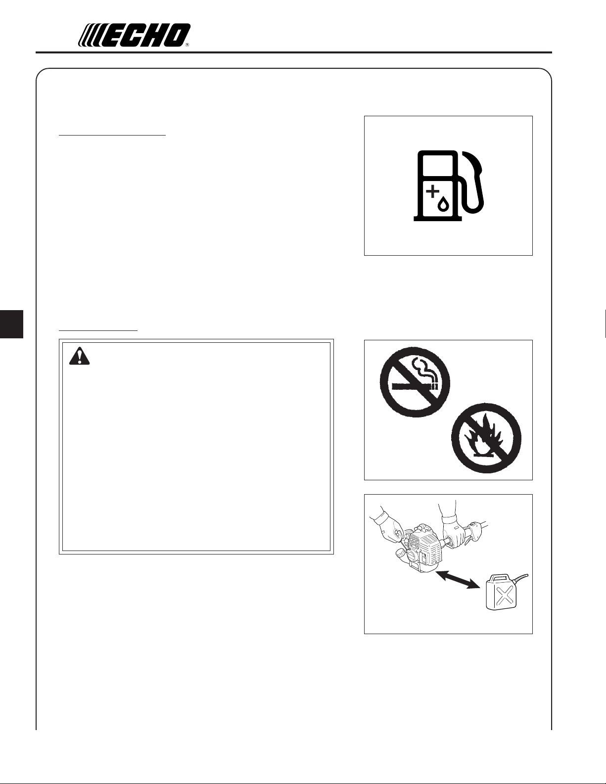
FUEL
DANGER
Fuel is VERY flammable. Use extreme care when mixing, storing
or handling, or serious personal injury may result.
- Use an approved fuel container.
- DO NOT smoke near fuel.
- DO NOT allow flames or sparks near fuel.
- Fuel tanks/cans may be under pressure.
Always loosen fuel caps slowly allowing pressure to equalize.
- NEVER refuel a unit when the engine is HOT!
- NEVER refuel a unit with the engine running.
- DO NOT fill fuel tanks indoors.
ALWAYS fill fuel tanks outdoors over bare ground.
- Securely tighten fuel cap after refuelling.
- Inspect for fuel leakage.
If fuel leakage is found, do not start or operate unit until leakage
is repaired.
After Refuelling;
3 m
- Wipe any spilled fuel from the unit.
- Move at least 3 m from refuelling location before starting.
After Use;
- DO NOT store a unit with fuel in its tank.
Leaks can occur.
Return unused fuel to an approved fuel storage container.
PERSONAL CONDITION & SAFETY EQUIPMENT
W ARNING
Hedge Clipper users risk injury to themselves and others if the shaft hedge clipper is used improperly and or
safety precautions are not followed. Proper clothing and safety gear must be worn when operating a shaft
hedge clipper.
Page 5

HEDGE CLIPPER
Physical Condition --
Your judgment and physical dexterity may not be good:
- if you are tired or sick,
- if you are taking medication,
- if you have taken alcohol or drugs.
Operate unit only if you are physically and mentally well.
Eye Protection --
Eye protection goggles that meet CE requirements were included
with your trimmer. Wear these goggles whenever you operate the
shaft hedge clipper.
Face & Head Protection --
When trimming overhead, wear head protection meeting CE with a
full face shield.
OPERATOR’S MANUAL
5
Hand Protection --
Wear no-slip, heavy duty work gloves to improve your grip on the
Shaft Hedge Clipper handles. Gloves also reduce the transmission of
machine vibration to your hands. Special vibration reducing gloves
such as ECHO’s Pro-Comfort are designed to provide additional
comfort.
Hearing Protection --
ECHO recommends wearing hearing protection whenever unit is
used.
Proper Clothing --
Wear snug fitting, durable clothing;
- Pants should have long legs, shirts with long sleeves.
- DO NOT WEAR SHORTS,
- DO NOT WEAR TIES, SCARVES, JEWELRY.
Wear sturdy work shoes with non-skid soles;
- DO NOT WEAR OPEN TOED SHOES,
- DO NOT OPERATE UNIT BAREFOOTED.
Hot Humid Weather --
Heavy protective clothing can increase operator fatigue which may
lead to heat stroke. Schedule heavy work for early morning or late
afternoon hours when temperatures are cooler.
Page 6

6
SAFE OPERATION
DETERMINE OPERATION AREA
- Review the area to be trimmed. Look for hazards that could
contribute to unsafe conditions. DO NOT operate unit if any wires
(power, telephone, cable, etc.) are closer than 5 m to any part of
the operator or unit.
- Spectators and fellow workers must be warned, and children and
animals prevented from coming nearer than 15 m while the Hedge
Clipper is in use.
Operation
Use Proper Clothing & Equipment
- Before starting the unit, equip yourself and any other person
working within the 15 m Safety Zone with the required Protective
Equipment and clothing.
- Check that loop (front) handle and shoulder strap/ or shoulder/
waist harness is adjusted for safe, comfortable operation.
Avoid Hot Surfaces
- During operation, the complete unit, especially the drive shaft
housing, power head, muffler area and gear box may become very
hot, too hot to touch. Avoid contact during and immediately after
operation.
Keep A Firm Grip
- Hold the front and rear handles with both hands with thumbs and
fingers tightly encircling the handles.
Keep A Solid Stance
- Maintain footing and balance at all times. Do not stand on slippery,
uneven or unstable surfaces. Do not work in odd positions or on
ladders. Do not over reach.
15 m
15 m
Adjust Cutting Angle
- Never adjust blade angle while standing.
- Only adjust cutting angle with unit resting flat on the ground, with
the switch in the “STOP” position.
Page 7

HEDGE CLIPPER
OPERATOR’S MANUAL
EXTENDED OPERATION / EXTREME CONDITIONS
Vibration and Cold --
It is believed that a condition called Raynaud’s Phenomenon, which
affects the fingers of certain individuals may be brought about by
exposure to vibration and cold. Exposure to vibration and cold may
cause tingling and burning sensations followed by loss of color and
numbness in the fingers. The following precautions are strongly
recommended because the minimum exposure which might trigger
the ailment is unknown.
• Keep your body warm, especially the head, neck, feet, ankles,
hands and wrists.
• Maintain good blood circulation by performing vigorous arm
exercises during frequent work breaks and also by not smoking.
• Limit the hours of operation. Try to fill each day with jobs where
operating the trimmer or other hand-held power equipment is not
required.
• If you experience discomfort, redness and swelling of the fingers
followed by whitening and loss of feeling, consult your physician
before further exposing yourself to cold and vibration.
7
Repetitive Stress Injuries --
It is believed that overusing the muscles and tendons of the fingers,
hands, arms and shoulders may cause soreness, swelling, numbness,
weakness and extreme pain in those areas. Certain repetitive hand
activities may put you at a high risk for developing a Repetitive
Stress Injury (RSI). An extreme RSI condition is Carpal Tunnel
Syndrome (CTS), which could occur when your wrist swells and
squeezes a vital nerve that runs through the area. Some believe that
prolonged exposure to vibration may contribute to CTS. CTS can
cause severe pain for months or even years.
To reduce the risk of RSI / CTS, do the following:
• Avoid using your wrist in a bent, extended or twisted position.
Instead try to maintain a straight wrist position. Also, when
grasping, use your whole hand, not just the thumb and index finger.
• Take periodic breaks to minimize repetition and rest your hands.
• Reduce the speed and force with which you do the repetitive
movement.
• Do exercises to strengthen the hand and arm muscles.
• See a doctor if you feel tingling, numbness or pain in the fingers,
hands, wrists or arms. The sooner RSI/CTS is diagnosed, the more
likely permanent nerve and muscle damage can be prevented.
Page 8

8
DESCRIPTION
HCAA-2400A ; SRM-2306/2306ES
HCAA-2403A ; SRM-220ES
HCAA-2404A ; SRM-265/265ES
4
HCAA-2401A ; PAS-265ES
2
1
2
3
5
6
Safety decal
3
Part Number;
890617-12361
7
4
5
6
1. OPERATOR’S MANUAL - Read and understand this manual before operation. Keep manual in a safe
location for future reference, i.e., operation, maintenance and specifications.
2. BLADES - Double reciprocating blades mounted to a blade support bar. Double-sided blades are capable of
cutting on either side of the blade.
3. BLADE INDEXING RING- Pull ring out and turn 1/4 turn to lockout position when adjusting blade angle.
4. BLADE COVER - Used to cover blade during transport and storage. Remove blade cover before using unit.
5. GEAR HOUSING ASSEMBLY - Gear housing contains drive gears for transmitting power to cutting blades.
Pivoting design permits blades to articulate 180 degrees in 15-degree increments.
6. BLADE ADJUSTMENT HANDLE - Provides secure hand grip for adjusting cutting blade angle.
7. HAND GUARD / BLADE LOCK - Locks blade in place for travel / storage. Always assure blade cover is
installed when locking blade.
8
8. FRONT DRIVE SHAFT GRIP - Cushioned hand grip for gripping drive shaft assembly.
Page 9

HEDGE CLIPPER
OPERATOR’S MANUAL
SPECIFICATIONS
HCAA-2400A
HCAA-2403A HCAA-2401A
HCAA-2404A
Mass
Unit with specified cutting blade kg 2.2 2.7
Cutting device
Type Dual action, double sided
Length mm 510
Pitch mm 35
Height mm 21
Gear ratio 3.95 reduction
External Dimensions
Length mm 810 1015
Width mm 110 130
Height mm 100 95
9
ASSEMBLY
GEAR BOX / DRIVE SHAFT
Tools Required: 4 mm Hexagonal Wrench, Cross Head Screw-
driver.
Parts Required: Power Head/Drive Shaft Assembly and Gear Box/
Blade Assembly.
NOTE
Hedge Clipper Blades are very sharp. Wear gloves to protect hands.
1. Slide the Gear Box/Blade Assembly on the Drive Shaft. Be
certain the Flex Drive Shaft engages the hole in Driver Gear.
2. Align the locating bolt with the locating hole in the Drive Shaft
Housing, tighten screw and clamping bolt.
Clamping bolt
Locating hole
Screw
Page 10
10
PRE-OPERATION
FUEL
Fuel Requirements
Fuel is a mixture of regular grade petrol and an air-cooled 2-stroke
engine oil of reputable brand name. Minimum 89 Octane unleaded
petrol is recommended. Do not use fuel containing methyl alcohol or
more than 10 % of ethyl alcohol.
Recommended mixture ratio; 50 : 1 (2 %) for ISO-L-EGD Standard
(ISO/CD 13738), JASO FC, FD grade and ECHO Premium 50 : 1
oil.
- Do not mix directly in engine fuel tank.
- Avoid spilling petrol or oil. Spilled fuel should always be wiped
up.
- Handle petrol with care, it is highly inflammable.
- Always store fuel in approved container.
Handling Fuel
DANGER
Fuel is VERY flammable. Use extreme care when mixing, storing
or handling, or serious personal injury may result.
- Use an approved fuel container.
- DO NOT smoke near fuel.
- DO NOT allow flames or sparks near fuel.
- Fuel tanks/cans may be under pressure.
Always loosen fuel caps slowly allowing pressure to equalize.
- NEVER refuel a unit when the engine is HOT!
- NEVER refuel a unit with the engine running.
- DO NOT fill fuel tanks indoors.
ALWAYS fill fuel tanks outdoors over bare ground.
- Securely tighten fuel cap after refuelling.
- Inspect for fuel leakage.
If fuel leakage is found, do not start or operate unit until leakage
is repaired.
After Refuelling;
- Wipe any spilled fuel from the unit.
- Move at least 3 m from refuelling location before starting the
engine.
After use;
- DO NOT store a unit with fuel in its tank.
Leaks can occur.
Return unused fuel to an approved fuel storage container.
3 m
Page 11

HEDGE CLIPPER
Storage;
Fuel storage laws vary by locality. Contact your local government
for the laws affecting your area. As a precaution, store fuel in an
approved, air tight container. Store in a well ventilated, unoccupied
building, away from sparks and flames. Do not store fuel longer than
30 days.
IMPORTANT
Stored fuel ages. Do not mix more fuel than you expect to use in
thirty (30) days.
IMPORTANT
Stored two-stroke fuel may separate. ALWAYS shake fuel
container thoroughly before each use.
OPERATOR’S MANUAL
SM TW T FS
1234567
8 9 10 11 12 13 14
15 16 17 18 19 20 21
22 23 24 25 26 27 28
29 30 31
11
EQUIPMENT CHECK
Before operation a complete check of the unit must be performed;
- Check unit for loose/missing nuts, bolts and screws. Tighten and/or
replace as needed.
- Inspect fuel lines, tank and area around carburettor for fuel leaks.
DO NOT operate unit if leaks are found.
- Check that the blade assembly is firmly attached and in safe
operating condition. Dull, loose or damaged blades should not be
used.
Page 12

12
OPERATION
ADJUSTING
CUTTING ANGLE
WARNING
Never adjust cutting assembly with engine running.
WARNING
Hedge clipper blades are sharp. Always wear gloves when
adjusting cutting assembly.
WARNING
DO NOT stand hedge clipper on end when adjusting cutting
angle, otherwise serious injury may result
1. Place unit on a flat clear area. Assure stop switch is in the
“STOP” position.
Indexing ring
¼ turn
2. Pull out indexing ring, and turn ¼ turn to lockout position.
3. Turn hedge clipper ¼ turn so that indexing ring faces downward.
4. Release hand-guard blade lock with right hand, while holding
blade-adjustment handle with left hand.
5. Rotate blades to desired cutting position.
6. Turn indexing ring ¼ turn to lock blade in place.
WARNING
Gear case assembly becomes HOT during use. Always grip
assembly at blade-adjustment handle when making cutting
angle adjustments, otherwise serious injury may result.
Hand-guard blade lock
Hand-guard
blade lock
Adjustment
handle
Page 13

HEDGE CLIPPER
HEDGE TRIMMING
1. Hold trimmer firmly and squeeze throttle trigger to accelerate
engine.
2. Tilt trimmer so cutting teeth are angled slightly toward the hedge
or shrub and proceed to cut.
WARNING
Never remove hands from unit when blades are moving.
OPERATOR’S MANUAL
13
WARNING
The engine continues running even when the blades have
stopped due to an obstruction. If this occurs, stop the engine,
disconnect ignition cable and remove the obstruction.
Page 14
14
MAINTENANCE
Your ECHO product is designed to provide many hours of trouble free service.
Regular scheduled maintenance will help achieve that goal.
If you are unsure or are not equipped with the necessary tools, you may want to take your unit to an ECHO
Service Dealer for maintenance.
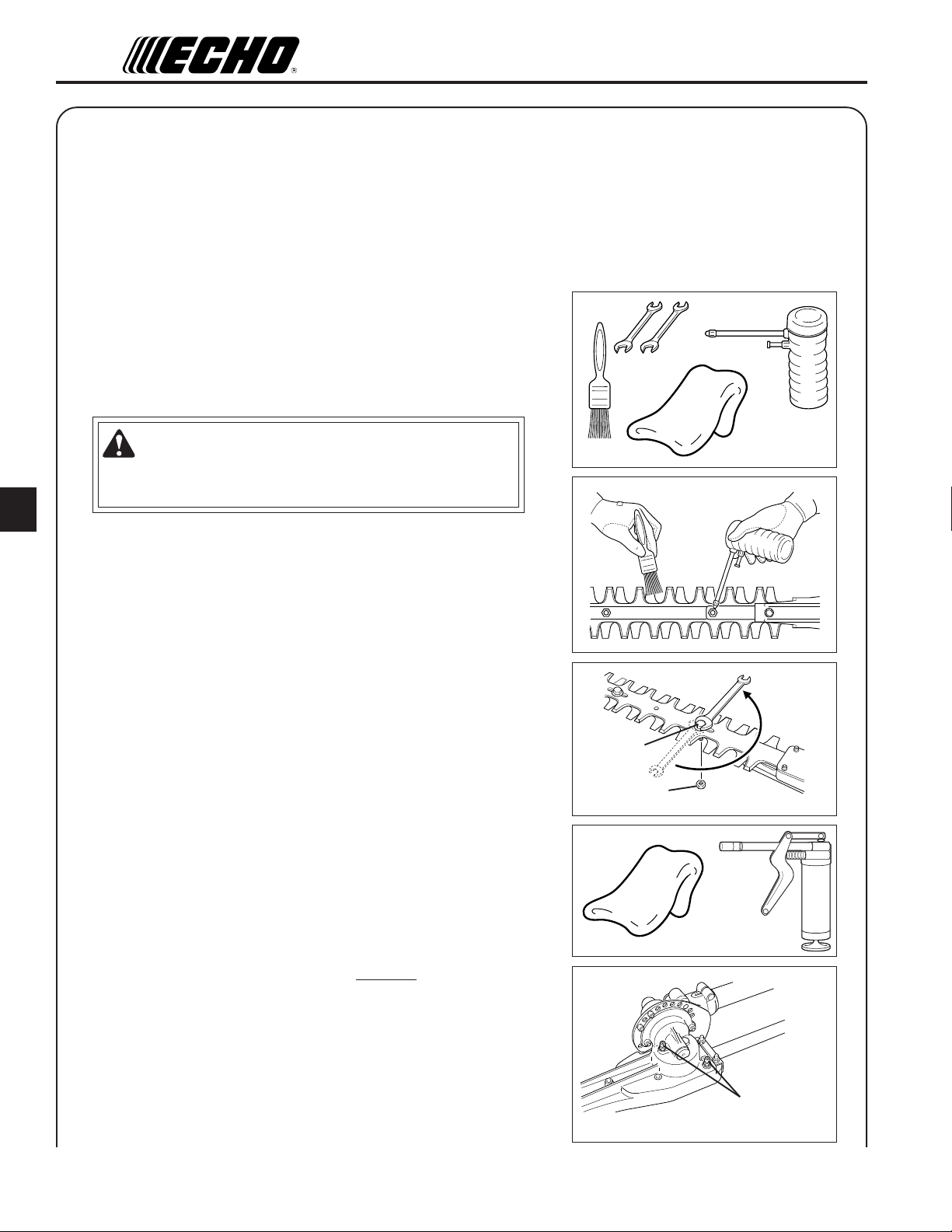
CLEAN & LUBRICATION
Blades
Tools Required: Clean Rag, Brush, Oil Can, (2) 10 mm Wrench.
Parts Required: 20W Engine Oil (lubrication), 50 : 50 mixture of
Kerosene and 20W Oil (cleaning).
W ARNING
Shaft Hedge Clipper Blades are very sharp. Wear gloves to protect
hands, otherwise serious personal injury may result.
1. Brush loose debris from blade and coat both sides of blade with
the 50 : 50 cleaning mixture.
2. Allow cleaning mixture to soften the remaining gummy residue
then wipe it from the blade.
3. Apply clean oil to the entire length of the blade. Be certain the
blade bolts are lubricated.
4. Wipe excess oil from the blade before putting the unit back in
service.
5. Check blade tightness. Tighten blade bolts until snug with 10
mm wrench. Loosen bolts 1/2 turn. Hold bolts from turning and
tighten locknuts with other 10 mm wrench.
Gear housing assembly
Tools required: Grease Gun with Lithium Grease, Rag.
Parts required: Lithium Based Grease.
1. Clean dirt from grease fittings.
2. Carefully pump grease in each fitting. DO NOT force grease.
Too much pressure will force grease past seals and cause damage.
Apply 1-2 pumps of grease every 15-20 hours of operation.
Loosen
1/2 turn
Bolt
Locknut
Grease
fitting
Page 15

HEDGE CLIPPER
Drive shaft assembly
NOTE
Hedge Clipper drive shaft should be greased every 25-50 hours of
operation.
Tools required: 4 mm Hexagonal Wrench, 8 mm Open End
Wrench, Clean Rag, Small Brush.
Parts required: Lithium Based Grease.
WARNING
Shaft Hedge Clipper Blades are very sharp. Wear gloves to protect
hands, otherwise serious personal injury may result.
1. Loosen gear box locating bolt and clamping bolt. Remove the
gear box from the drive shaft housing.
2. Pull the drive shaft from the housing, wipe clean and recoat with
a thin coating (15 mL) of lithium based grease.
OPERATOR’S MANUAL
Clamping bolt
Locating bolt
15
3. Slide the flexible shaft back into the drive housing being careful
not to get dirt on the flex shaft.
4. Install the gear box assembly.
SHARPENING BLADES
Tools required: Flat file, Small Screwdriver.
Parts required: Gear box gasket, Lithium Based Grease.
NOTE
Blade sharpening requires removal of blades from the unit. Step
by step instruction are included in the Service Manual that apply
to your model.
NOTE
Hedge Clipper Blades are very sharp. Wear gloves to protect
hands.
1. Use screwdriver to separate upper and lower cutters equal
distance apart.
2. File each edge carefully. Follow the original shape of the blade.
43º
Drive shaft
6mm Radius
IMPORTANT
If a power grinder is used DO NOT allow blade to over heat.
3. Lubricate blades. See “Blade Lubrication Instructions”, page 14
this section.
Page 16

16
DECLARA TION “CE” OF CONFORMITY
The undersigned manufacturer:
KIORITZ CORPORATION
7-2 SUEHIROCHO 1-CHOME
OHME ; TOKYO 198-871 1
JAPAN
declares that the hereunder specified new unit:
PORT ABLE HEDGE TRIMMER
Brand: ECHO
T ype : HCAA-2400A,HCAA-2401A
HCAA-2403A,HCAA-2404A
assembled by:
ECHO, INCORPORA TED
400 Oakwood Road
Lake Zurich, Ilinois 60047-1564
U.S.A.
complies with:
*the requirements of Directive 98/37/EC (1998)
(use of harmonized standard ISO 10517 (EN 774))
*the requirements of Directive 2004/108/EC
(use of harmonized standards EN 50081-1, EN 50082-1, EN 55014 & EN
55022)
*the requirements of Directive 2002/88/EC
*the requirements of Directive 2000/14/EC
Conformity assessment procedure followed ANNEX V
SRM-2306/
SRM-2306ES + PAS-265ES+
HCAA-2400A HCAA-2401A
Measured sound power level dB(A) 105 108
Guaranteed sound power level dB(A) 108 111
SRM-265/
SRM-220ES + SRM265ES+
HCAA-2403A HCAA-2404A
Measured sound power level dB(A) 104 108
Guaranteed sound power level dB(A) 107 111
Page 17

HEDGE CLIPPER
OPERATOR’S MANUAL
HCAA-2400A Serial Number S56435001001 and up
HCAA-2401A Serial Number S56535001001 and up
HCAA-2403A Serial Number S56635001001 and up
HCAA-2404A Serial Number S56735001001 and up
Tokyo,
December 1st 2007 Authorized Representative in Europe:
Company: Countax Limited
Address: Countax House, Haseley
Trading Estate,
Great Haseley , Oxfordshire
OX44 7PF, U.K.
Mr . Harry Handkammar
17
GB
Page 18

7-2 SUEHIROCHO 1-CHOME, OHME, TOKYO 198-8711, JAPAN
PHONE: 81-428-32-6118. FAX: 81-428-32-6145.
GB
© 2007
X753-003 43 1
X753 224-790 2
 Loading...