

Page 1

Shaf t Hedge Clipper
Operator's Manual
MODEL HCA-265
WARNING
Read rules for safe operation and instructions carefully. ECHO provides an Operator's
Manual and a Safety Manual. Both must be read and understood for proper and safe operation. Failure to do so could result in serous injury.
X7502024603
X750010183
12/07
Page 2

2
INTRODUCTION
Welcome to the ECHO family. This ECHO product was designed and manufactured to provide long life and on-the-job
dependability. Read and understand this manual and the SAFETY MANUAL you found in the same package. You will
find both easy to use and full of helpful operating tips and SAFETY messages.
THE OPERAT OR'S MANUAL
Read and understand this manual before operation. Keep it in a safe
place for future reference. It contains specifications and information for
operation, starting, stopping, maintenance, storage and assembly
specific to this product.
THE SAFETY MANUAL
Read and understand this manual before operation. Keep it in a safe
place for future reference. It explains possible hazards involved with the
use of Hedge Clippers and what measures you should take to make their
use safer.
TABLE OF CONTENTS
Introduction ...................................................................... 2
- The Operator's Manual............................................... 2
- The Safety manual...................................................... 2
Safety ................................................................................ 3
- Manual Safety Symbols and Important Information.. 3
- International Symbols................................................ 3
- Personal Conditions and Safety Equipment .............. 4
- Equipment .................................................................. 6
Emissions Control ............................................................. 6
Description ....................................................................... 7
Contents ........................................................................... 9
Assembly .......................................................................... 9
- Drive Shaft Assembly / Power Head.......................... 9
- Throttle Linkage and Ignition Leads........................ 10
- Balance and Adjust Unit.......................................... 11
Operation ........................................................................ 11
- Fuel .......................................................................... 11
- Adjusting Cutting Angle ......................................... 13
- Rotate Cutter Assembly .......................................... 14
- Starting Cold Engine................................................ 1 4
- Starting Warm Engine.............................................. 15
- Stopping Engine ...................................................... 16
- Hedge Trimming ...................................................... 16
Copyright© 2008 By Echo, Incorporated
All Rights Reserved.
Maintenance ................................................................... 17
- Skill Level................................................................. 17
- Maintenance Intervals............................................. 17
- Air Filter................................................................... 18
- Fuel Filter ................................................................. 18
- Spark Plug................................................................ 19
- Cooling System........................................................ 1 9
- Exhaust System........................................................ 2 0
- Carburetor Adjustment ............................................ 2 1
- Lubrication............................................................... 22
- Sharpening Blades................................................... 24
- Blade Adjustment .................................................... 24
Troubleshooting ............................................................. 25
Storage............................................................................ 26
Specifications.................................................................. 27
Servicing Information...................................................... 28
- Parts/Serial Number ................................................. 28
- Service ..................................................................... 28
- ECHO Consumer Product Support........................... 2 8
- Warranty Card ......................................................... 2 8
- Additional or Replacement Manuals ....................... 2 8
Specifications, descriptions and illustrative material in this
literature are as accurate as known at the time of publication, but are subject to change without notice. Illustrations
may include optional equipment and accessories, and may
not include all standard equipment.
Page 3
SHAFT HEDGE CLIPPER
OPERATOR'S MANUAL
SAFETY
MANUAL SAFETY SYMBOLS AND IMPORTANT INFORMATION
Throughout this manual and on the product itself, you will find safety alerts and helpful, informational messages preceded by symbols or key words. The following is an explanation of those symbols and key words and what they mean to
3
DANGER
The safety alert symbol accompanied by the word
“DANGER” calls attention to an act or condition
which WILL lead to serious personal injury or death
if not avoided.
W ARNING
The safety alert symbol accompanied by the word
“WARNING” calls attention to an act or condition
which CAN lead to serious personal injury or death
if not avoided.
CAUTION
The safety alert symbol accompanied by the word
“CAUTION” calls attention to an act or condition
which may lead to minor or moderate personal injury
if not avoided.
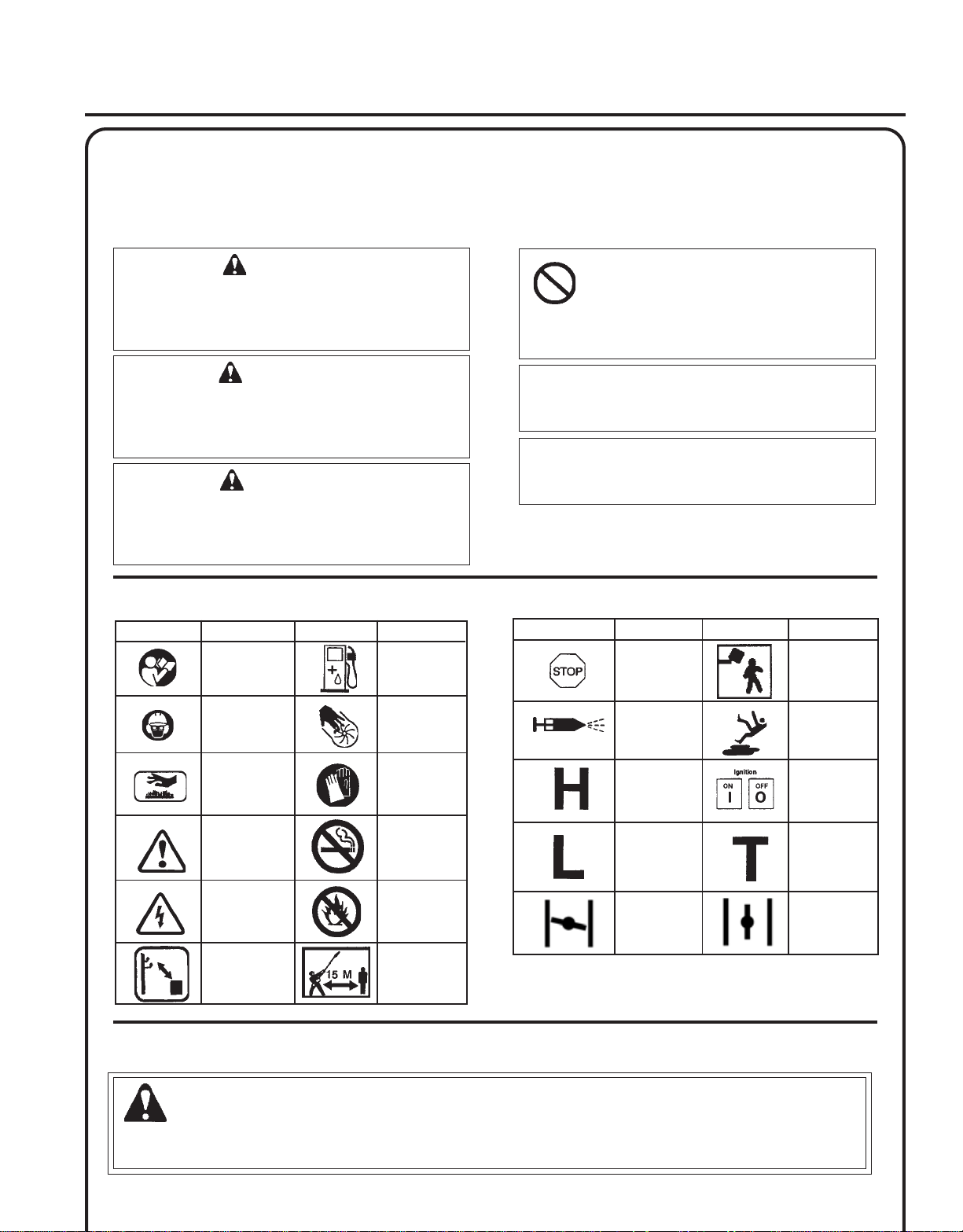
INTERNA TIONAL SYMBOLS
Symbol form/shape
Symbol
description/application
Read and
understand
Operator's Manual.
Wear eyes, ears
and head
protection
Symbol form/shape
Symbol
description/application
Fuel and oil
mixture
Finger Severing
CIRCLE AND SLASH SYMBOL
This symbol means the specific action
shown is prohibited. Ignoring these
prohibitions can result in serious or fatal
injury.
NOTE
This enclosed message provides tips for use, care
and maintenance of the unit.
IMPORTANT
The enclosed message provides information
necessary for the protection of the unit.
Symbol form/shape
Symbol
description/application
Emergency stop
Primer bulb
Symbol form/shape
Symbol
description/application
Plan retreat path
from falling
objects.
Wear slip
resistant foot
wear.
Hot
Surface
Safety/Alert
Avoid all power
lines. This unit is
not insulated
against electrical
current.
Do not operate
closer than 15 M
(50 ft.) from
electrical
hazards.
Wear hand
protection. Use
two handed.
DO NOT smoke
near fuel.
DO NOT allow
flames or sparks
near fuel.
Keep bystanders
at least 15 meters
(50 feet) away.
Carburetor
adjustment
- High speed
mixture
Carburetor
adjustment
- Low speed
mixture
Choke Control
"Cold Start"
Position
(Choke Closed)
PERSONAL CONDITION AND SAFETY EQUIPMENT
W ARNING
Hedge Clipper users risk injury to themselves and others if the hedge clipper is used improperly and or safety
precautions are not followed. Proper clothing and safety gear must be worn when operating a hedge clipper.
Ignition
ON/OFF
Carburetor
adjustment
- Idle speed
Choke Control
"Run"
Position
(Choke Open)
Page 4

4
Physical Condition
Your judgment and physical dexterity may not be good:
• if you are tired or sick,
• if you are taking medication,
• if you have taken alcohol or drugs.
Operate unit only if you are physically and mentally well.
Eye Protection
Eye protection that meets ANSI Z87.1 or CE requirements must be worn whenever you operate the unit.
Hand Protection
Wear no-slip, heavy duty work gloves to improve your grip on the handles. Gloves also reduce the transmission of
machine vibration to your hands.
Hearing Protection
Wear hearing protection. ECHO recommends wearing hearing protection whenever unit is used.
Proper Clothing
Wear snug fitting, durable clothing;
• Pants should have long legs, shirts with long sleeves.
• DO NOT WEAR SHORTS,
• DO NOT WEAR TIES, SCARFS, JEWELRY.
Wear protective hair covering to contain long hair.
Wear sturdy work shoes with nonskid soles;
• DO NOT WEAR OPEN TOED SHOES,
• DO NOT OPERATE UNIT BAREFOOTED.
Wear no-slip, heavy duty work gloves.
Hot Humid Weather
Heavy protective clothing can increase operator fatigue which may lead to heat stroke. Schedule heavy work for early
morning or late afternoon hours when temperatures are cooler.
Vibration and Cold
It is believed that a condition called Raynaud’s Phenomenon, which affects the fingers of certain individuals, may be
brought about by exposure to vibration and cold. Exposure to vibration and cold may cause tingling and burning sensations, followed by loss of color and numbness in the fingers. The following precautions are strongly recommended,
because the minimum exposure which might trigger the ailment is unknown.
• Keep your body warm, especially the head, neck, feet, ankles, hands,
and wrists.
• Maintain good blood circulation by performing vigorous armexercises
during frequent work breaks, and also by not smoking.
• Limit the hours of operation. Try to fill each day with jobs where
operating the unit or other hand-held power equipment is not
required.
• If you experience discomfort, redness, and swelling of the fingers
followed by whitening and loss of feeling, consult your physician
before further exposing yourself to cold and vibration.
Page 5
SHAFT HEDGE CLIPPER
OPERATOR'S MANUAL
Repetitive Stress Injuries
It is believed that overusing the muscles and tendons of the fingers, hands, arms, and shoulders may cause soreness,
swelling, numbness, weakness, and extreme pain in those areas. Certain repetitive hand activities may put you at a high
risk for developing a Repetitive Stress Injury (RSI). An extreme RSI condition is Carpal Tunnel Syndrome (CTS), which
could occur when your wrist swells and squeezes a vital nerve that runs through the area. Some believe that prolonged
exposure to vibration may contribute to CTS. CTS can cause severe pain for months or even years.
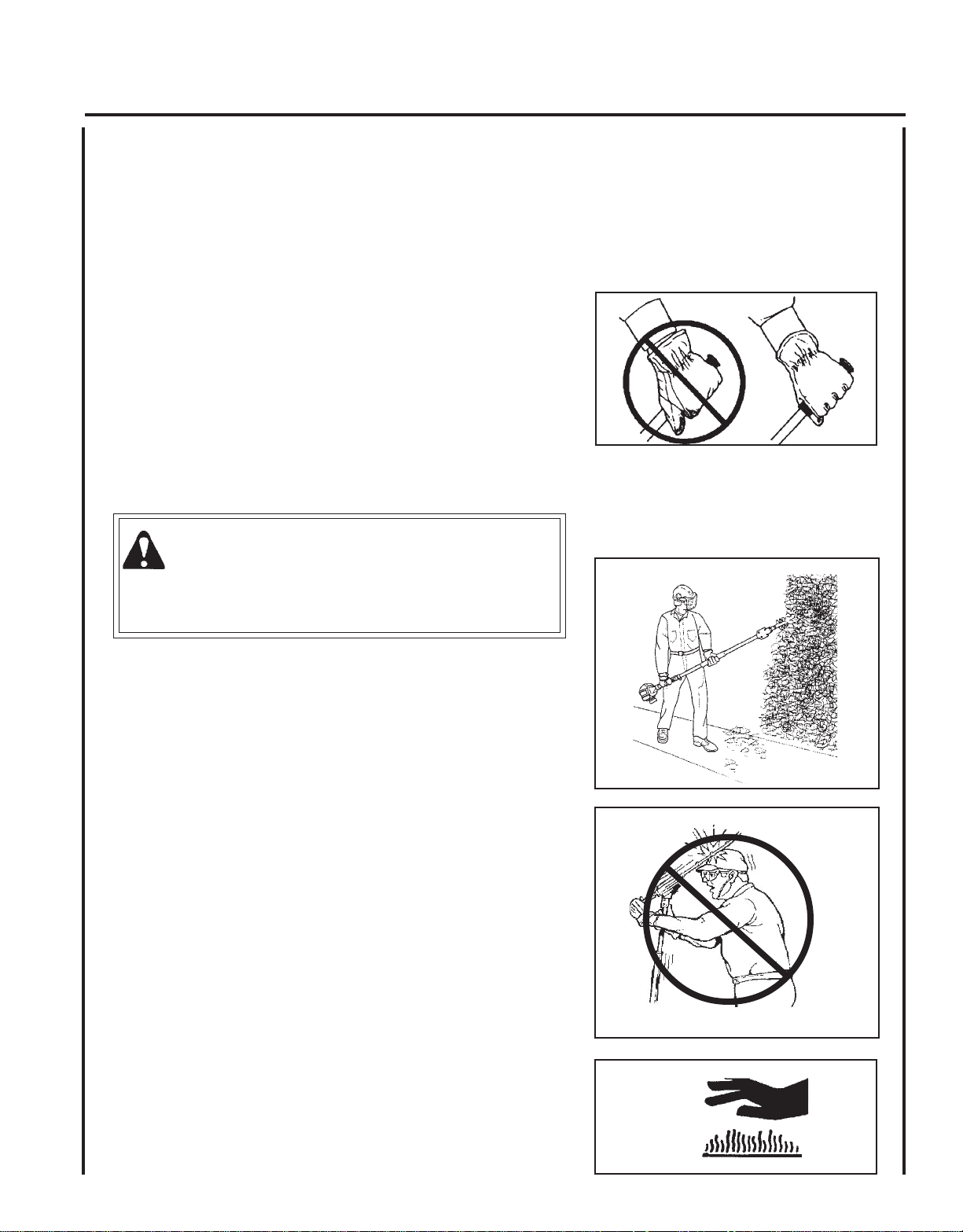
To reduce the risk of RSI/CTS, do the following:
• Avoid using your wrist in a bent, extended, or twisted position.
Instead try to maintain a straight wrist position. Also, when grasping,
use your whole hand, not just the thumb and index finger.
• Take periodic breaks to minimize repetition and rest your hands.
• Reduce the speed and force with which you do the repetitive movement.
• Do exercises to strengthen the hand and arm muscles.
• Immediately stop using all power equipment and consult a doctor if
you feel tingling, numbness, or pain in the fingers, hands, wrists, or
arms. The sooner RSI/CTS is diagnosed, the more likely permanent
nerve and muscle damage can be prevented.
5
DANGER
Do not operate this product indoors or in inadequately ventilated
areas. Engine exhaust contains poisonous emissions and can cause
serious injury or death.
Read the Manuals
• Provide all users of this equipment with the Operator's Manual and
Safety Manual for instructions on Safe Operation.
Clear the Work Area
• Spectators and fellow workers must be warned, and children and
animals prevented from coming nearer than 15 m (50 ft.) while the unit
is in use.
Keep a Firm Grip
• Hold the front and rear handles with both hands, with thumbs and
fingers tightly encircling the handles.
Keep a Solid Stance
• Maintain footing and balance at all times. Do not stand on slippery,
uneven or unstable surfaces. Do not work in odd positions or on
ladders. Do not over reach.
Cutting Angle Adjustments
• Only adjust cutting blade angle with unit flat on the ground, with the
engine stop switch in the “STOP” position. Never adjust cutting
angle with unit standing upright.
Avoid Contact With Gear Box Assembly During Use
• Gear box assembly becomes hot during use. Avoid contact with gear
box assembly when using unit or making cutting angle adjustments.
Avoid Hot Surfaces
• Keep exhaust area clear of flammable debris. Avoid contact during
and immediately after operation.
Page 6
6
EQUIPMENT
W ARNING
Use only ECHO approved attachments. Serious injury may result from the use of a non-approved attachment
combination. ECHO, INC. will not be responsible for the failure of cutting devices, attachments, or accessories which
have not been tested and approved by ECHO. Read and comply with all safety instructions listed in this manual and
safety manual.
• Check unit for loose/missing nuts, bolts, and screws. Tighten and/or replace as needed.
• Inspect fuel lines, tank and area around carburetor for fuel leaks. DO NOT operate unit if leaks are found.
• Never adjust blades when the engine is operating.
• Inspect hand guard for damage. Replace if damaged or missing.
• Check that the blade assembly is firmly attached and in safe operating condition. Dull, loose or damaged blades should
not be used.
WARNING
Moving parts can amputate fingers or cause severe injuries. Keep hands, clothing and loose objects away from all
openings.
• ALWAYS stop engine, disconnect spark plug, and make sure all moving parts have come to a complete stop
before removing obstructions, clearing debris, or servicing unit.
• DO NOT start or operate unit unless all guards and protective covers are properly assembled to unit.
• NEVER reach into any opening while the engine is running. Moving parts may not be visible through openings.
EMISSION CONTROL
EPA Phase 2 / C.A.R.B. TIER III
The emission control system for the engine is EM/TWC (Engine Modification and 3-way Catalyst) and for the fuel tank
the Control System is EVAP (Evaporative Emissions). Evaporative emission may be applicable to California models only.
IMPORTANT ENGINE INFORMATION
ENGINE FAMILY: 8EHXS.0254KG DISPLACEMENT: 25.4 CC
EMISSION COMPLIANCE PERIOD : 300 HRS.
THIS ENGINE MEETS U.S. EPA PH2 EXH AND 2007 AND
LATER CALIFORNIA EXH AND EVAP EMISSION REGULATIONS FOR S.O.R.E. REFER TO OWNER'S MANUAL FOR
MAINTENANCE SPECIFICATIONS AND ADJUSTMENTS.
Emission Control Label (located on Engine) (EXAMPLE ONLY, information on label varies by FAMILY).
PRODUCT EMISSION DURABILITY
The 300 hour emission durability compliance period is the time span selected by the manufacturer certifying the
engine emissions output meets applicable emissions regulations, provided that approved maintenance procedures are
followed as listed in the Maintenance Section of this manual.
Page 7
SHAFT HEDGE CLIPPER
OPERATOR'S MANUAL
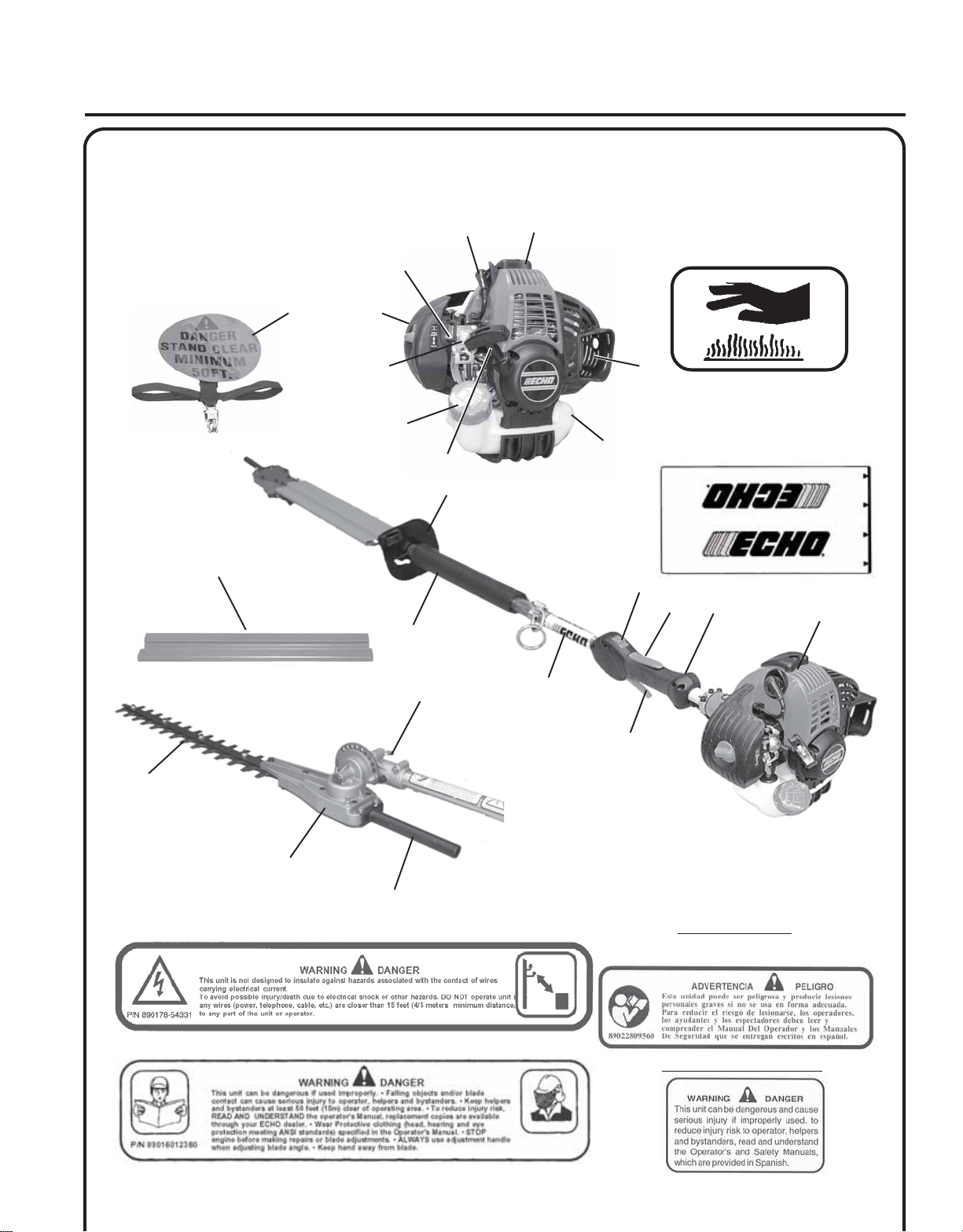
DESCRIPTION
Locate these safety decals on your unit. Make sure the decals are legible and that you understand and follow the
instructions on them. If a decal cannot be read, a new one can be ordered from your ECHO dealer. See PARTS ORDERING instructions for specific information.
21
20
22
Hot Decal (near muffler)
P/N 89016006361
7
13
23
19
18
17
10
14
15
16
5
4
6
11
12
P/N X505001930
3
2
1
7
P/N 89017854331
P/N 89016012360
8
9
Shaft Decal
Spanish Decal
P/N 89022809560
English Translation
Page 8

8
1. POWER HEAD - Factory Assembled. Includes the Engine, Clutch, Fuel System, Ignition System and Recoil Starter.
2. GRIP, RIGHT HAND, REAR - Cushioned grip for Right Hand.
3. THROTTLE TRIGGER LOCKOUT - This lever must be held during starting. Operation of the throttle trigger is
prevented unless throttle trigger lockout lever is engaged.
4. STOP SWITCH - Controls engine ignition. Move switch forward to start and run engine, back to “STOP” position
to stop engine.
5. HAND GUARD / BLADE LOCK - Locks blade in place for travel / storage. Always assure blade cover is installed
when locking blade.
6. BLADE INDEXING RING- Pull ring out and turn 1/4 turn to lockout position when adjusting blade angle.
7. BLADES - Double reciprocating blades mounted to a blade support bar. Double-sided blades are capable of cutting
on either side of the blade.
8. GEAR HOUSING ASSEMBLY - Gear housing contains drive gears for transmitting power to cutting blades. Pivot-
ing design permits blades to articulate 180 degrees in 15-degree increments.
9. BLADE ADJUSTMENT HANDLE - Provides secure hand grip for adjusting cutting blade angle.
10. FRONT DRIVE SHAFT GRIP - Cushioned hand grip for gripping drive shaft assembly.
11. DRIVE SHAFT ASSEMBLY - Includes the flex drive shaft, rear handle assembly, harness ring, cushioned front shaft
grip, and safety decals.
12. THROTTLE TRIGGER - Controls engine speed. Spring loaded to return to idle when released. During acceleration,
depress gradually for best operating technique.
13. BLADE COVER - Used to cover blade during transport and storage. Remove blade cover before using unit.
14. SPARK ARRESTOR - CATALYTIC MUFFLER / MUFFLER -The muffler or catalytic muffler controls exhaust noise
and emission. The spark arrestor screen prevents hot, glowing particles of carbon from leaving the muffler. Keep
exhaust area clear of flammable debris.
15. FUEL TANK - Contains fuel and fuel filter.
16. RECOIL STARTER HANDLE - Pull handle slowly until starter engages, then quickly and firmly. DO NOT pull rope
all the way out or allow the handle to snap back, damage to the starter will occur.
17. FUEL TANK CAP - Covers and seals fuel tank opening.
18. PURGE BULB - Pumping purge bulb before starting engine draws fresh fuel from the fuel tank, purging air from the
carburetor. Pump purge bulb until fuel is visible and flows freely in the clear fuel tank return line. Pump purge bulb
an additional 4 or 5 times.
19. AIR CLEANER - Contains replaceable filter element.
20. CHOKE CONTROL - Located on the top of the air cleaner housing. Move the lever to "COLD START" ( ) to
close the choke for Cold Starting. Move lever to "RUN" ( ) position after engine fires.
21. SPARK PLUG - Provides spark to ignite fuel mixture.
22. TOP GUARD - Protects arm from the hot engine.
23. SHOULDER HARNESS - An adjustable strap that suspends the unit from the operator.
Page 9

SHAFT HEDGE CLIPPER
OPERATOR'S MANUAL
CONTENTS
Due to packaging restrictions, some assembly is required.
After opening the carton, check for damage. Immediately notify your retailer or ECHO Dealer of damaged or missing
parts. Use the contents list to check for missing parts.
___ 1 - Power Head
___ 1 - Drive Shaft /Gear Case Assembly
___ 1 - Operators Manual
___ 1 - Hedge Clipper Safety Manual
___ 1 - Warranty Statement
___ 1 - Warranty Registration Card
___ 1 - Safety Glasses
___ 1 - Shoulder Harness
___ 1 - Blade Cover
___ 1 - Echo Power Blend X TM 2-stroke oil sample
___ 1 - T-Wrench
___ 1 - 4 mm Hex Wrench
___ 1 - 8 mm/10 mm Wrench
9
ASSEMBLY
Tools Required: 4 mm hex wrench, 8mm x 10mm Open End Wrench,
Screwdriver
Parts Required: Power Head, Drive Shaft/Gear Case Assembly
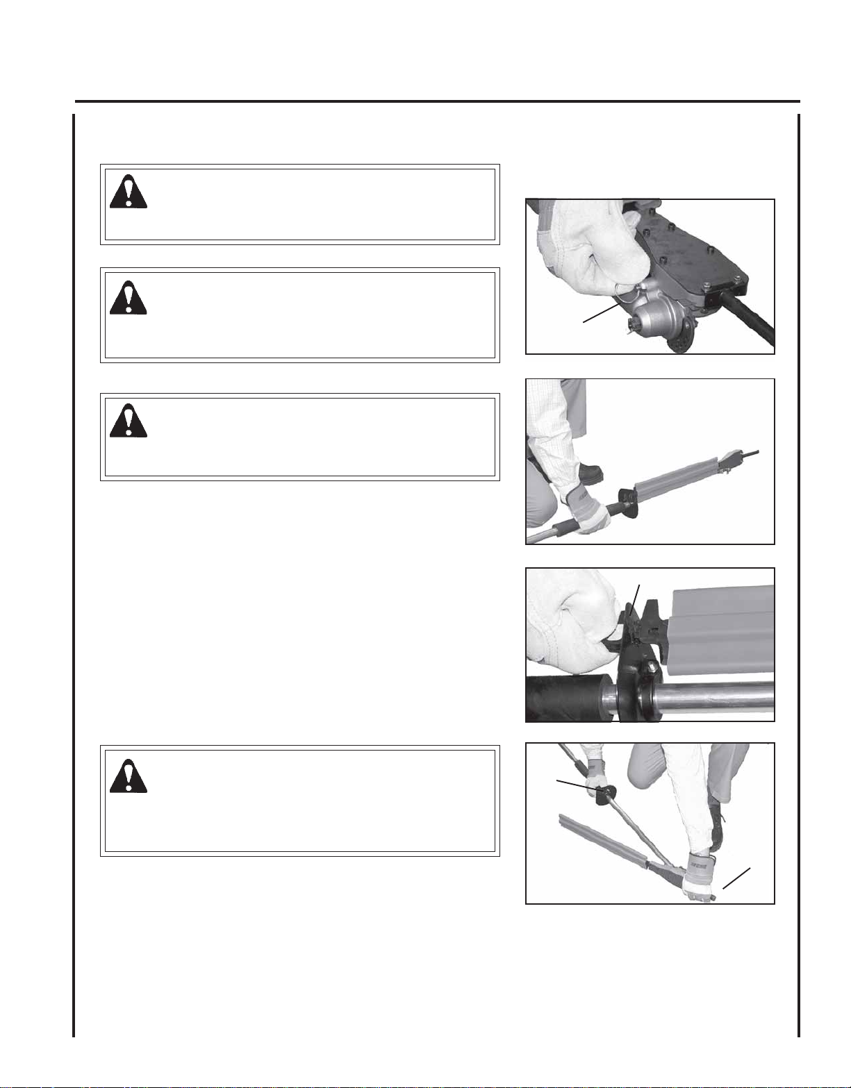
DRIVE SHAFT/POWER HEAD
1. Stand power head upright on a level surface.
2 . Loosen the two (2) drive shaft clamp bolts (B) at engine drive shaft
clamp, and remove center drive shaft location bolt (A).
3 . Carefully fit driveshaft assembly to engine making sure that
inner drive shaft engages clutch mount.
4 . Turn drive shaft housing until locating hole lines up with location
hole in clamp and install center drive shaft location bolt (A).
B
A
B
Page 10

10
NOTE
Gear Housing must be aligned properly with engine. Aligning
center locating hole in driveshaft housing with center drive shaft
bolt (A) provides correct alignment.
5 . Tighten two (2) drive shaft clamp bolts (B) securely.
6. Route throttle linkage and ignition lead assembly along shaft and
clip as shown.
THROTTLE LINKAGE AND IGNITION LEADS
1 . Close choke and remove air filter cover.
2 . Place throttle linkage (C) through adjustment fixture (D) and install
wire end into large carburetor throttle swivel hole (E). Check throttle
for freedom of movement and that wide open throttle / low idle
extremes are adjusted properly. The throttle linkage must be
adjusted by moving the adjustment fixture (D). Consult with your
Echo Dealer for correct adjustment procedure.
3 . Connect 2 ignition stop leads (F, G) from throttle cable tubing to 2
ignition leads (F, G) on engine.
B
B
D
F
A
C
E
4 . Secure ignition leads against engine housing with clip (H).
5 . Install air filter and cover.
G
H
H
Page 11

BALANCE AND ADJUST UNIT
1. Loosen harness clamp screw.
2. Put on harness and attach unit to harness.
3 . Slide harness clamp up or down for comfortable operation
4 . Tighten harness clamp screw.
SHAFT HEDGE CLIPPER
OPERATOR'S MANUAL
11
OPERATION
WARNING
Moving parts can amputate fingers or cause severe injuries. Keep hands, clothing and loose objects away from all
openings. Always stop engine, disconnect spark plug, and make sure all moving parts have come to a complete
stop before removing obstructions, clearing debris, or servicing unit.
NOTICE: Use of unmixed, improperly mixed, or fuel older than 90 days, (stale fuel), may cause hard starting, poor
performance, or severe engine damage and void the product warranty. Read and follow instructions in the Storage
section of this manual.
FUEL
WARNING
Alternative fuels, such as E-20 (20% ethanol), E-85 (85% ethanol) or any fuels not meeting ECHO requirements are
NOT approved for use in ECHO 2-stroke gasoline engines. Use of alternative fuels may cause performance problems,
loss of power, overheating, fuel vapor lock, and unintended machine operation, including, but not limited to, improper
clutch engagement. Alternative fuels may also cause premature deterioration of fuel lines, gaskets, carburetors and
other engine components.
Fuel Requirements
Gasoline - Use 89 Octane [R+M/2] (mid grade or higher) gasoline known to be good quality. Gasoline may contain up to
10% Ethanol (grain alcohol) or 15% MTBE (methyl tertiary-butyl ether). Gasoline containing methanol (wood alcohol) is
NOT approved.
Page 12
12
Two Stroke Oil - A two-stroke engine oil meeting ISO-L-EGD (ISO/CD 13738) and J.A.S.O. FC/FD Standards must be
used. Echo brand premium Power Blend X TM Universal 2-Stroke Oil meets these standards. Engine problems due to
inadequate lubrication caused by failure to use an ISO-L-EGD (ISO/CD 13738) and J.A.S.O. FC/FD certified oil, such as
Echo premium Power Blend X TM, will void the two-stroke engine warranty. (Emission related parts only are covered for
two years, regardless of two-stroke oil used, per the statement listed in the Emission Defect Warranty Explanation.)
IMPORTANT
Echo premium Power Blend X TM Universal 2-Stroke Oil may be mixed
at 50:1 ratio for application in all Echo engines sold in the past
regardless of ratio specified in those manuals.
Handling Fuel
DANGER
Fuel is VERY flammable. Use extreme care when mixing, storing or
handling or serious personal injury may result.
• Use an approved fuel container.
• DO NOT smoke near fuel.
• DO NOT allow flames or sparks near fuel.
• Fuel tanks/cans may be under pressure. Always loosen fuel caps
slowly allowing pressure to equalize.
• NEVER refuel a unit when the engine is HOT or RUNNING!
• DO NOT fill fuel tanks indoors. ALWAYS fill fuel tanks outdoors
over bare ground.
• DO NOT overfill fuel tank. Wipe up spills immediately.
• Securely tighten fuel tank cap and close fuel container after
refueling.
• Inspect for fuel leakage. If fuel leakage is found, do not start or
operate unit until leakage is repaired.
• Move at least 3m (10 ft.) from refueling location before starting
the engine.
After use
• DO NOT store a unit with fuel in its tank.
Leaks can occur. Return unused fuel to an
approved fuel storage container.
Storage - Fuel storage laws vary by locality.
Contact your local government for the laws
affecting your area. As a precaution, store
fuel in an approved, airtight container. Store
in a well-ventilated, unoccupied building,
away from sparks and flames.
IMPORTANT
Stored fuel ages. Do not mix more fuel
than you expect to use in thirty (30)
days, ninety (90) days when a fuel
stabilizer is added.
IMPORTANT
Stored two-stroke fuel may separate.
ALWAYS shake fuel container thoroughly before each use.
Mixing Instructions
1 . Fill an approved fuel container with half of the required amount of
gasoline.
2. Add the proper amount of 2-stroke oil to gasoline.
3 . Close container and shake to mix oil with gasoline.
4 . Add remaining gasoline, close fuel container, and remix.
IMPORTANT
Spilled fuel is a leading cause of hydrocarbon emissions. Some
states may require the use of automatic fuel shut-off containers to
reduce fuel spillage.
.S.UCIRTEM
SAGLIOSAGLIO
snollaG.zo.lFretiL.cc
1
2
5
6.2
2.5
31
4
8
02
oitaR1:05-xiMliOotleuF
08
061
004
Page 13
ADJUSTING CUTTING ANGLE
WARNING
Never adjust cutting assembly with engine running.
WARNING
Hedge clipper blades are sharp. Always wear gloves when
adjusting cutting assembly.
WARNING
DO NOT stand hedge clipper on end when adjusting cutting angle,
otherwise serious injury may result
SHAFT HEDGE CLIPPER
OPERATOR'S MANUAL
A
13
1 . Place unit on a flat clear area. Assure stop switch is in the “STOP”
position.
2 . Pull out indexing ring (A), and turn ¼ turn to lockout position.
3 . Turn hedge clipper ¼ turn so that indexing ring faces downward.
4 . Release hand-guard blade lock (B) with right hand, while holding
blade-adjustment handle (C) with left hand.
5. Rotate blades to desired cutting position.
6 . Turn indexing ring ¼ turn to lock blade in place.
WARNING
Gear case assembly becomes HOT during use. Always grip
assembly at blade-adjustment handle when making cutting angle
adjustments, otherwise serious injury may result.
B
B
C
Page 14

14
ROT ATE CUTTER ASSEMBLY
Always use the unit from the right-hand side of your body – NEVER
from the left side. Rotate cutter assembly 180 degrees on driveshaft in
order to avoid cutting directly above your head, and to avoid contact
with hot muffler.
1 . Loosen gearcase clamping screw (A), hand guard clamping screw
(B), and remove gearcase locating screw (C).
2 . Rotate cutter assembly 180-degrees on driveshaft until locating
hole in driveshaft is visible through locating hole in gearcase.
3 . Install gearcase locating screw (C), and securely tighten all
hardware.
WARNING
Hedge Clipper blades are very sharp. Wear gloves to protect hands
when rotating cutter assembly or serious personal injury may
result.
B
C
A
WARNING
During operation, the complete unit, especially the drive shaft
housing and gearcase may become too hot to touch. Avoid contact
when rotating cutter assembly.
STARTING COLD ENGINE
NOTE
The blade cover is used for transportation and storage. Remove
blade cover before using the unit.
WARNING
The attachment will operate immediately when the engine starts and
could result in loss of control and possible serious injury. Keep
movable parts of the attachment off the ground and away from
objects that could become entangled or thrown.
1. Stop Switch
Move stop switch button (A) forward away from the STOP
position.
A
B
2. Close Choke
Move choke lever (B) to Cold Start ( ) Position.
C
D
Page 15

3. Purge Bulb
Pump purge bulb (C) until fuel is visible and flows freely in the clear
fuel tank return line. Pump bulb an additional 4 or 5 times.
SHAFT HEDGE CLIPPER
OPERATOR'S MANUAL
15
4. Recoil Starter
Lay the unit on a flat area and keep movable attachment parts clear
of all obstacles. Firmly grasp right hand grip and throttle trigger
lockout with left hand and fully depress throttle trigger to wide
open position. Rapidly pull recoil starter handle/rope (D) until
engine fires (or maximum five [5] pulls).
5. Choke
After engine fires (or five [5] pulls), move choke lever back to
“Run” ( ) position. Hold throttle trigger and throttle trigger
lockout fully depressed and pull recoil starter handle/rope until
engine starts and runs. Release throttle trigger and allow unit to
warm up at idle for several minutes.
NOTE
If engine does not start with choke in Run position after 5 pulls,
repeat instructions 2 - 5.
6. Throttle Trigger
After engine warm up, gradually depress throttle trigger to increase
engine RPM to operating speed.
STARTING WARM ENGINE
The starting procedure is the same as Cold Start except DO NOT close
the choke, and do not depress throttle trigger to wide open position.
B
C
D
D
A
W ARNING
The attachment should not move at idle, otherwise serious
personal injury may result.
NOTE
If attachment moves, readjust carburetor according to “Carburetor
Adjustment” instructions in this manual or see your ECHO Dealer.
1. Stop Switch
Move stop switch button (A) away from the STOP position.
2. Purge Bulb
Pump purge bulb (C) until fuel is visible and flows freely in the
“Clear” fuel return line. Pump bulb an addition 4 or 5 times.
3. Recoil Starter
Lay the unit on a flat area and keep movable attachment parts clear
of all obstacles. Rapidly pull recoil starter handle/rope (D) until
engine fires.
NOTE
If engine does not start after 5 pulls, use Cold Start Procedure.
C
D
D
Page 16

16
STOPPING ENGINE
1. Throttle
Release throttle and allow engine to return to idle before shutting off
engine.
2. Stop Switch
Move stop switch button (A) to STOP position.
W ARNING
If engine does not stop when stop switch is moved to STOP
position, close choke - COLD START position - to stall engine.
Have your ECHO dealer repair stop switch before using shaft
hedge clipper again.
IMPORTANT
Always install blade cover, and return cutting assembly to folded/
locked position for travel/storage.
HEDGE TRIMMING
A
1 . Hold trimmer firmly and squeeze throttle trigger to accelerate
engine.
2 . Tilt trimmer so cutting teeth are angled slightly toward the hedge or
shrub and proceed to cut.
WARNING
Never remove hands from unit when blades are moving.
WARNING
The engine continues running even when the blades have stopped
due to an obstruction. If this occurs, stop the engine, disconnect
ignition cable and remove the obstruction.
Page 17
SHAFT HEDGE CLIPPER
OPERATOR'S MANUAL
MAINTENANCE
WARNING
Moving parts can amputate fingers or cause severe injuries. Keep hands, clothing and loose objects away from all
openings. Always stop engine, disconnect spark plug, and make sure all moving parts have come to a complete
stop before removing obstructions, clearing debris, or servicing unit. Allow unit to cool before performing service.
Wear gloves to protect hands from sharp edges and hot surfaces.
Your ECHO product is designed to provide many hours of trouble free service. Regular scheduled maintenance will help
achieve that goal. If you are unsure or are not equipped with the necessary tools, you may want to take your unit to an
ECHO Service Dealer for maintenance. To help you decide whether you want to DO-IT-YOURSELF or have the ECHO
Dealer do it, each maintenance task has been graded. If the task is not listed, see your ECHO Dealer for repairs.
SKILL LEVEL
Level 1 = Easy to do. Most required tools come with unit.
Level 2 = Moderate difficulty. Some specialized tools may be required.
Level 3 = Experience required. Specialized tools are required. ECHO recommends
that the unit be returned to your ECHO dealer for service
ECHO offers REPOWERTM Maintenance Kits and Parts to make your maintenance job easier.
17
MAINTENANCE INTERVALS
/TNENOPMOC
METSYS
troPtsuahxErednilyCnobraceD/naelC/tcepsnI 3 C/I
sedalBneprahSnae
retliFriAecalpeR/naelC/tcepsnI 1 C/I*R
ekohCnaelC/tcepsnI
retliFleuFecalpeR/tcepsnI 1 I*R
skael,metsySleuFecalpeR/tcepsnI 1 *)4(I)4(I
metsySgnilooCnaelC/tcepsnI 2 C/I
ro
tserrAkrapSrelffuMecalpeR/tcepsnI 2 *I
xelF(tfahSevirD
)sledoMelbaC
gnisuoHraeGesaerG 2 )2(I
sedalBna
epoRretratSlioceRnaelC/tcepsnI 1 *C/I
gulPkrapSnaelC/tcepsnI 2 C/I*R
lC/tcepsnI 3 )3(I
esaerG 2 )1(I
elC/tcepsnI 1 )3(C/I
ECNANETNIAM
ERUDECORP
D'QER
LLIKS
LEVEL
2 C/I
ROYLIAD
EROFEB
ESU
YREVE
LEUFER
serudecorPecnanetniaMflesruoY-tI-oD
3
SHTNOM
09RO
SRUOH
serudecorPecnanetniaMrelaeDohcEdednemmoceR
6
SHTNOM
072RO
SRUOH
YLRAEY
006
SRUOH
stloB/stuN/swercSecalpeR
-ETONTNATROPMI deriuqerfoycneuqerfehtenimretedlliwecneirepxeruoydnaesulaut
.ecnanetniam
)1( OHCEylppA
)2( OHCEylppA
)3( .esugnirudyllacidoirepsedalbetacirbuL.dedeensaneprahsdnanaelcdnaedalbtcepsnI
)4( .yti
* ..noitcepsnignirudraewr
MT
EBUL
®
MT
EBUL
®
/nethgiT/tcepsnI 1 *R/I
SEDOCRETTELERUDECORPECNANETNIAM NAELC=C,ECALPER=R,TCEPSNI=I:
:SETONERUDECORPECNANETNIAM
.sruoh52yreve
sruoh52-51yreve
cA.mumixameranwohsslavretniemiT
oegamadfognidnifehtnodesaberaecalperotsnoitadnemmocerllA
rgetninoissimeniatniamotecnanetniamralugereriuqerTONODsknatleufevitaropavewoL
Page 18

18
AIR FILTER
Level 1.
Tools required: 25 or 50 mm (1 or 2 in.) Cleaning brush
Parts required: Air Filter
1. Close choke (Cold Start Position [
entering the carburetor throat when the air filter is removed. Brush
accumulated dirt from air cleaner area.
2 . Remove air filter cover. Brush dirt from inside cover.
3 . Remove air filter and lightly brush debris from filter. Replace filter if
it is damaged, fuel soaked, very dirty, or the rubber sealing edges
are deformed.
4 . If filter can be reused, be certain it:
• Fits tightly in the air filter cavity.
• Is installed with the original side out.
5 . Install air filter cover.
). This prevents dirt from
FUEL FILTER
Level 1.
Tools required: 200-250 mm (8-10 in.) length of wire with one end bent
into a hook, clean rag, funnel, and an approved fuel
container.
Parts required: Fuel Filter
DANGER
Fuel is VERY flammable. Use extreme care when mixing, storing or
handling.
1 . Use a clean rag to remove loose dirt from around fuel cap and
empty fuel tank.
2 . Use the “fuel line hook” to pull the fuel line and filter from the
tank.
3 . Remove the filter from the line and install the new filter.
Page 19
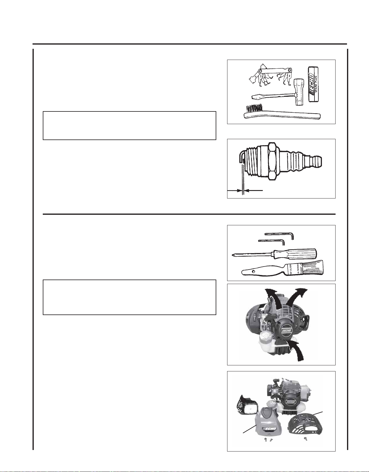
SPARK PLUG
Level 2.
Tools Required: T-Wrench, feeler gauge, soft metal brush
Parts Required: Spark Plug NGK BPM-8Y
IMPORTANT
Use only NGK BPM-8Y spark plug (BPMR-8Y in Canada) otherwise
severe engine damage may occur.
1 . Remove spark plug and check for fouling, worn and rounded
center electrode.
2 . Clean the plug or replace with a new one. DO NOT sand blast to
clean. Remaining sand will damage engine.
SHAFT HEDGE CLIPPER
OPERATOR'S MANUAL
19
3. Adjust spark plug gap by bending outer electrode.
4 . Tighten spark plug to 150-170 kg/cm (130-150 in. lb.).
COOLING SYSTEM
Level 2.
Tools required: Cross Head Screwdriver, 3 & 4 mm Hex Wrench,
Cleaning Brush, 25 - 50 mm (1 - 2 in.)
Parts Required: None if you are careful.
IMPORTANT
To maintain proper engine operating temperatures, cooling air
must pass freely through the cylinder fin area. This flow of air
carries combustion heat away from the engine.
Overheating and engine seizure can occur when:
• Air intakes are blocked, preventing cooling air from reaching the
cylinder.
• Dust and grass build up on the outside of the cylinder. This build up
insulates the engine and prevents the heat from leaving.
0.65 mm
(0.026 in.)
Removal of cooling passage blockages or cleaning of cooling fins is
considered “Normal Maintenance.” Any failure attributed to lack of
maintenance is not warranted.
1 . Remove spark plug lead.
2 . Remove air cleaner cover.
3 . Remove muffler cover screw and muffler cover (A).
4 . Remove 2 engine cover screws and engine cover (B).
A
B
Page 20

20
IMPORTANT
DO NOT use a metal scraper to remove dirt from the cylinder fins.
5 . Use brush to remove dirt from the cylinder fins.
6 . Remove grass and leaves from the grid between the recoil starter
and fuel tank.
7. Assemble components in reverse order.
EXHAUST SYSTEM
Spark Arrestor Screen
Level 2.
Tools Required: Cross Head Screwdriver, 4mm Hex Wrench, Soft
Metal Brush
Parts Required: Spark Arrestor Screen, Gasket
1 . Remove spark plug lead.
2 . Remove muffler cover screw and muffler cover (A).
3 . Place piston at Top Dead Center (TDC) to prevent carbon/dirt from
entering cylinder.
4 . Remove spark arrestor screen (B), gasket (C), and exhaust guide (D)
from muffler body.
5 . Clean carbon deposits from muffler components.
NOTE
When cleaning carbon deposit, be careful not to damage the
catalytic element inside muffler.
6 . Replace screen if it is cracked, plugged or has holes burned
through.
7. Assemble components in reverse order.
Cylinder Exhaust Port
Level 3.
A
C
B
D
IMPORTANT
The cylinder exhaust port must be inspected and cleaned of excess
carbon every 3 months or 90 hours of operation in order to maintain
this engine within the emissions durability period. ECHO strongly
recommends that you return your unit to your ECHO dealer for this
important maintenance service.
Page 21
CARBURETOR ADJUSTMENT
Engine Break-In
New engines must be operated a minimum duration of two tanks of
fuel break-in before carburetor adjustments can be made. During the
break-in period your engine performance will increase and exhaust
emissions will stabilize. Idle speed can be adjusted as required.
High Altitude Operation
This engine has been factory adjusted to maintain satisfactory starting,
emission, and durability performance up to 1,000 feet above mean sea
level (MSL). To maintain proper engine operation above 1,000 feet
MSL the carburetor must be adjusted by an authorized ECHO service
dealer.
IMPORTANT
If the engine is adjusted for operation above 1,000 feet MSL, the
carburetor must be re-adjusted when operating the engine below
1,000 feet MSL, otherwise severe engine damage can result.
SHAFT HEDGE CLIPPER
OPERATOR'S MANUAL
21
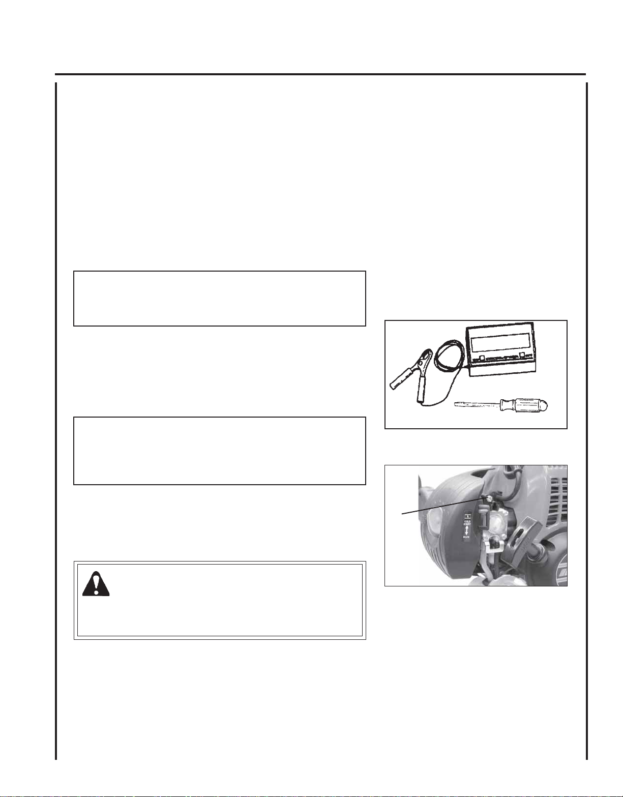
Level 3.
Tools required: Screwdriver, Tachometer (ECHO P/N
99051130017)
Parts required: None
NOTE
Every unit is run at the factory and the carburetor is set in
compliance with emission regulations. Carburetor adjustments,
other than idle speed, must be performed by an authorized ECHO
dealer.
1. Check idle speed and reset if necessary. If a tachometer is
available, idle speed screw (A) should be set to the specifications
found on page 27 "Specifications" of this manual. Turn idle screw
(A) clockwise to increase idle speed; counter clockwise to
decrease idle speed.
WARNING
When carburetor adjustment is completed, the cutting
attachment should not turn at idle, otherwise serious personal
injury may result.
A
Page 22

22
LUBRICA TION
Blades
Level 1.
Tools Required: Clean rag, brush , oil can
Parts Required: 20W Engine Oil (lubrication), 50-50 mixture of
kerosene and 20W oil (cleaning)
W ARNING
Always disconnect spark plug wire before servicing cutting
attachment. Blades are very sharp. Wear gloves to protect hands,
otherwise serious personal injury may result.
1. Brush loose debris from blade and coat both sides of blade with the
50-50 cleaning mixture.
2. Allow cleaning mixture to soften the remaining gummy residue
then wipe it from the blade.
3. Apply clean oil to the entire length of the blade. Be certain the
blade bolts are lubricated.
4 . Wipe excess oil from the blade before putting the unit back in
service.
Gear Housing Assembly
Level 2
Tools required: Grease gun, rag
Parts required: ECHO® LUBE
Lithium Based Grease
1 . Clean dirt from grease fittings (A).
2 . Carefully pump grease in each fitting (A). DO NOT force grease.
Too much pressure will force grease past seals and cause damage.
Apply 1-2 pumps of grease every 15-25 hours of operation.
TM
14 oz. cartridge P/N 91015 or
A
A
Page 23
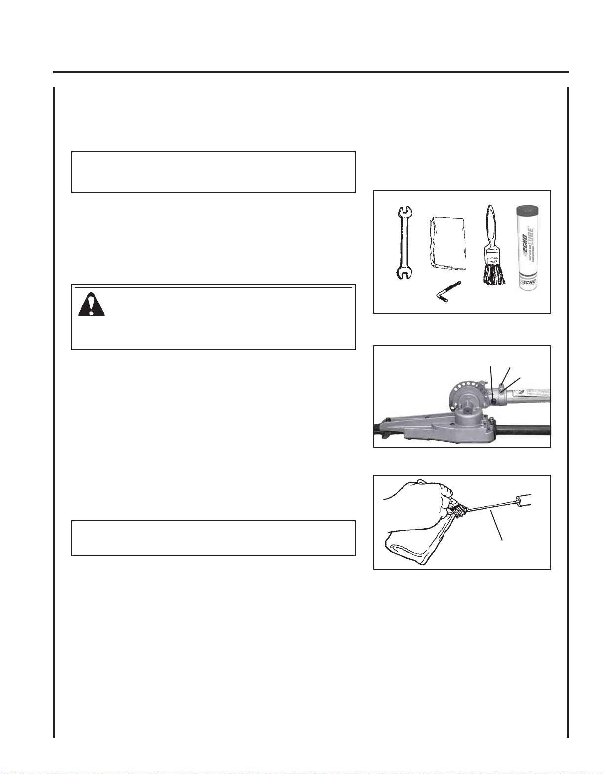
Drive Shaft Assembly
Level 1
NOTE
Hedge Clipper drive shaft should be greased every 25 hours of
operation.
Tools required: 4 mm hex wrench, 8mm open end wrench, clean rag,
small brush.
SHAFT HEDGE CLIPPER
OPERATOR'S MANUAL
23
Parts required: ECHO
Lithium-based Grease.
LUBETM 14 oz. cartridge P/N 91015 or
®
W ARNING
Blades are very sharp. Wear gloves to protect hands, otherwise
serious personal injury may result.
1 . Carefully remove locating screw (A) and loosen clamping screw (B).
Remove the flex drive shaft assembly from the gear housing.
2 . Pull the drive shaft (C) from the drive shaft assembly, and wipe
clean. Re-coat with a thin coating [1/2 oz. (15 ml)] of grease.
3 . Slide the flex shaft back into the drive shaft assembly, being careful
not to get dirt on the flex shaft.
4 . Align the locating screw hole in gear case with the locating hole in
drive shaft assembly, install and tighten locating screw (A), and
tighten clamping screw (B).
IMPORTANT
Flat edge of washer (D) must be against drive shaft.
D
A
B
C
Page 24

24
SHARPENING BLADES
Level 3.
Tools required: Flat file, screwdriver
Parts required: None
W ARNING
Hedge Clipper Blades are very sharp. Wear gloves to protect
hands.
IMPORTANT
Blades should only be removed and reinstalled by an Authorized
ECHO Servicing Dealer, otherwise premature wear or internal
damage may occur.
A
A
1 . Disconnect spark plug wire from spark plug.
2 . Slide blades to allow file clearance using slots (A) on bottom of
blades. Do not pry against cutting edges.
3 . Follow the original shape, and file each cutting edge carefully to
avoid damage to adjacent teeth. Maintain 6 mm (.25 in.) radius at
base of each tooth.
IMPORTANT
If a power grinder is used, DO NOT allow blade to over heat.
4 . Lubricate blades. See "Lubrication" on page 22.
5 . Connect spark plug wire.
BLADE ADJUSTMENT
Level 2.
Tools required: (2) 10 mm Sockets & Extensions
Parts required: None
WARNING
Hedge clipper blades are very sharp. Touching them may lead to
severe personal injury. Use a socket and extension when adjusting
blade bolts or blade locknuts in order to keep hands at a safe
distance from sharp blades.
6mm (.25 in.) Radius
45º
1. Tighten blade bolts (A) until snug, then loosen blade bolts 1/2
turn.
2 . Hold blade bolts (A) from turning using 10 mm socket & Extension,
and tighten blade lock nuts (B) with other 10 mm Socket &
Extension.
NOTE
Locking ability of Hedge Clipper blade lock nuts will diminish each
time they are removed. Replace if turning resistance is not felt when
installing locknuts.
B
A
Page 25

TROUBLESHOOTING
melborPkcehCsutatSesuaCydemeR
SHAFT HEDGE CLIPPER
OPERATOR'S MANUAL
TRAHCGNITOOHSELBUORTMELBORPENIGNE
25
ractaleuFroterubractaleufoNdeggolcreniartsleuF
roterub
deggolcenilleuF
roterubraC
rednilyctaleuFrednilyctaleufoNroterubraCrelaedohcEruoyeeS
leufhtiwtewrelffuMhcirooterutxiMleu
FekohcnepO
enignE
-sknarc
/drahstrats
t'nseod
trats
,snurenignE
roseidtub
tonseod
etarelecca
ylreporp
dnetakrapS
eriwgulpfo
gulptakrapSkrapsoNtce
retlifriAytridretlifriAraewlamroNecalper
retlifleuFytridretlifleuFseudiser/stnanimatnoCni
tnevleuFdeggulptnevleuFniseudiser/stnani
gulPkrapSnrow/ytridgulPraewlamroNecalperrotsujdadnanaelC
roterubraCtnemtsujdareporpmInoitarbiVtsujdA
metsySgnilooCmetsysgnilooC
krapsoNffohctiwspo
deggulp/ytrid
tS
melborplacirtcelE
hctiwskcolretnI
rrocnipagkrapS
nobrachtiwderevoC
leufhtiwdeluoF
evitcefedgulP
ecalpeR
leuf
matnoC
leuf
ninoitarepodednetxE
snoitacolytsud/ytrid
naelC
ecalperronaelC
ecalperronaelC
edohcEruoyeeS
rela
retlifriaecalper/naelC
roterubractsujdA
relaedohcEruoyeeS
NOothctiwsnruT
relaedohcEruoyeeS
relaedohcEruoyeeS
).ni620.0(mm56.ottsujdA
ecalperronaelC
rronaelC
ecalpe
gulpecalpeR
ronaelC
ecalperronaelC
rotserrAkrapS
neercS
seodenignE
ton
knarc
A/NA/NmelborpenignelanretnIr
rotserrakrapS
deggulpneercs
raewlamroNecalpeR
elaedohcEruoyeeS
DANGER
Fuel vapors are extremely flammable and may cause fire and/or explosion. Never test for ignition spark by grounding spark plug near cylinder plug hole, otherwise serious personal injury may result.
Page 26

26
STORAGE
WARNING
During operation the muffler or catalytic muffler and surrounding cover become hot. Always keep exhaust area clear
of flammable debris during transportation or when storing, otherwise serious property damage or personal injury may
result.
IMPORTANT
Always store and transport shaft hedge clippers in a stable, horizontal position. Always install blade cover, and
return cutting assembly to folded/locked position for travel/storage.
Long Term Storage (over 30 days)
Do not store your unit for a prolonged period of time (30 days or longer) without performing protective storage maintenance which includes the following:
1. Store unit in a dry, dust free place, out of the reach of children.
DANGER
Do not store in enclosure where fuel fumes may accumulate or reach an open flame or spark or serious personal
injury may result.
2. Place the stop switch in the "OFF" position.
3 . Remove accumulation of grease, oil, dirt and debris
from exterior of unit.
4 . Perform all periodic lubrication and services that are
required.
5 . Apply a light coating of clean 20W engine oil along
entire length of blades and on blade bolts.
6 . Install blade cover.
7. Tighten all the screws and nuts.
8. Drain the fuel tank completely and pull the recoil
starter handle several times to remove fuel from the
carburetor.
9 . Remove the spark plug and pour 7 cc (1/4 oz.) of
fresh, clean, two-stroke engine oil into the cylinder
through the spark plug hole.
A. Place a clean cloth over the spark plug hole.
B . Pull the recoil starter handle 2-3 times to distrib-
ute the oil inside the engine.
C. Observe the piston location through the spark
plug hole. Pull the recoil handle slowly until the
piston reaches the top of its travel and leave it
there.
10. Install the spark plug (do not connect ignition cable).
Page 27

SHAFT HEDGE CLIPPER
OPERATOR'S MANUAL
SPECIFICATIONS
MODEL -----------------------------------------------------HCA-265
Length------------------------------------------------------- 2365 mm (93.1in.)
Width--------------------------------------------------------245 mm (9.65 in.)
Height ------------------------------------------------------- 250 mm (9.84 in.)
Weight (dry) ------------------------------------------------7.12 kg (15.7 lb.)
Engine Type ------------------------------------------------Air cooled, two-stroke, single cylinder gasoline engine
Bore---------------------------------------------------------- 34.0 mm (1.34 in.)
Stroke-------------------------------------------------------- 28.0 mm (1.10 in.)
Displacement ----------------------------------------------- 25.4 cc (1.55 cu. in.)
Exhaust System --------------------------------------------Spark Arrestor Muffler w/Catalyst
Carburetor --------------------------------------------------Zama Model w/purge
Ignition System --------------------------------------------Flywheel Magneto, CDI (capacitor discharge ignition)
Spark Plug --------------------------------------------------BPM-8Y (Gap 0.65 mm (0.026 in.)
Fuel ---------------------------------------------------------- Mixed (Gasoline and Two-stroke Oil)
Fuel/Oil Ratio ----------------------------------------------- 50 : 1 Power Blend X™ ISO-L-EGD (ISO/CD 13738) and J.A.S.O.
M345-
FC/FD, two-stroke, air-cooled engine oil.
Gasoline -----------------------------------------------------Use 89 Octane unleaded. Do not use fuel containing methyl
alcohol, more than 10% ethyl alcohol or 15% MTBE. Do not use
alternative fuels such as E-20 or E-85.
Oil------------------------------------------------------------ Power Blend X TM Premium Universal 2-Stroke Oil
Fuel Tank Capacity ---------------------------------------- 0.5 lit. (16.9 US fl. oz.)
Starter System ----------------------------------------------Automatic Rewind Starter
Clutch ------------------------------------------------------- Centrifugal Type
Gear Case Ratio --------------------------------------------3.95 : 1
Cutter -------------------------------------------------------- Double Reciprocating Blade - Double Edge
Effective Length -----------------------------------------464 mm (18.5 in.)
Pitch ------------------------------------------------------- 35 mm (1.38 in.)
Maximum Diameter Cut
Soft Material ----------------------------------------------25.4 mm (1 in.)
Woody Material ------------------------------------------13 mm (1/2 in.)
Cutting Angle Adjustment --------------------------------30 ~ 180 Degrees in 15 degree increments
Idle Speed--------------------------------------------------- 2,600 - 3,200 RPM
Clutch Engagement Speed -------------------------------- 3,700 - 4,300 RPM
Wide Open Throttle Speed ------------------------------- 10,400 - 11,400 RPM
27
Page 28
SERVICING INFORMATION
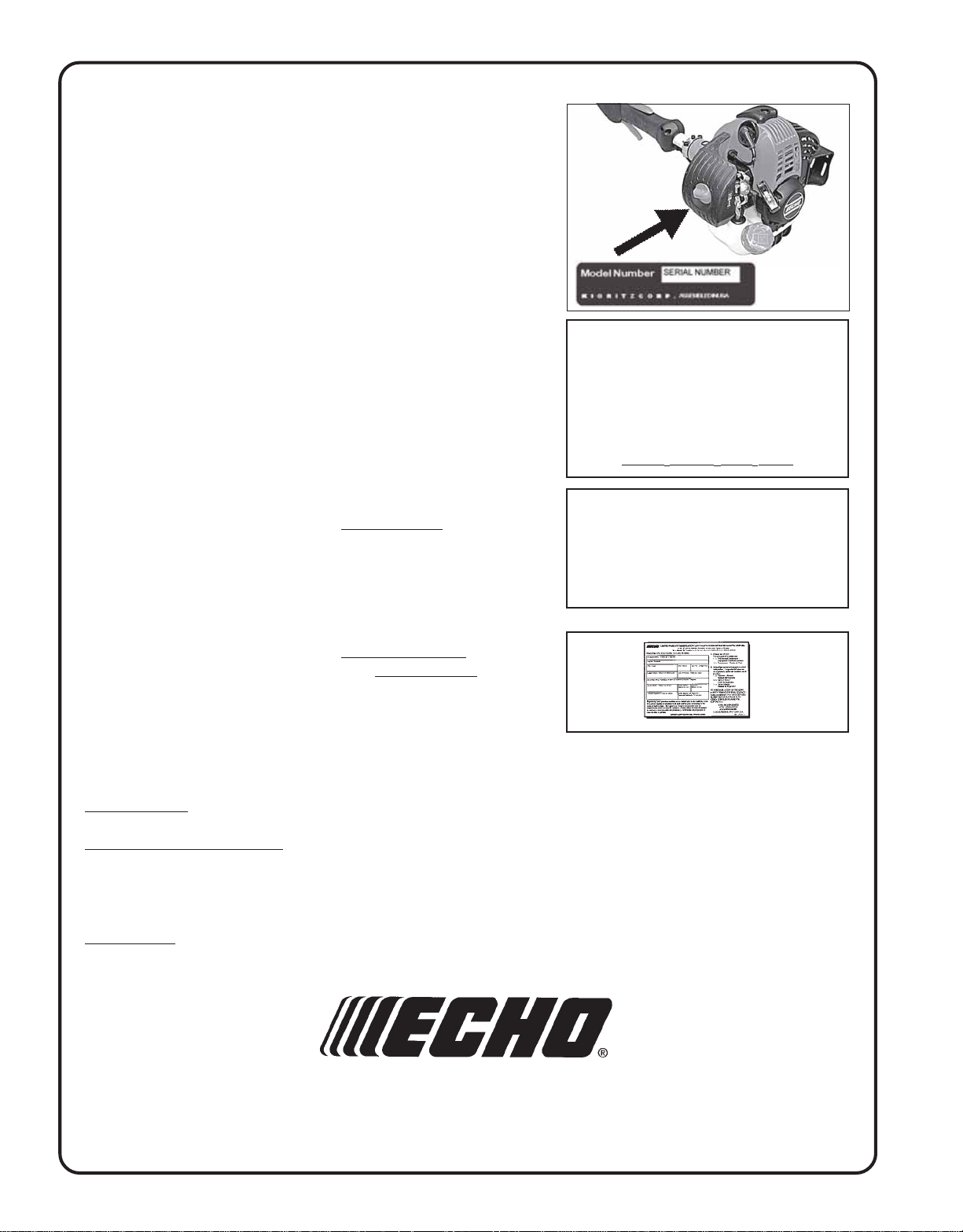
PARTS
Genuine ECHO Parts and ECHO REPOWER™ Parts and Assemblies for
your ECHO products are available only from an Authorized ECHO
Dealer. When you do need to buy parts always have the Model Number
and Serial Number of the unit with you. You can find these numbers on
the engine housing. For future reference, write them in the space
provided below.
/SERIAL NUMBER
Model Number _____________ Serial Number ____________
SERVICE
An Authorized ECHO Service Dealer must perform Service of this
product during the warranty period. For the name and address of the
Authorized ECHO Service Dealer nearest you, ask your retailer or call: 1800-432-ECHO (3246). Dealer information is also available on our Web
Site. When presenting your unit for Warranty service/repairs, proof of
purchase is required.
ECHO CONSUMER PRODUCT SUPPORT
If you require assistance or have questions concerning the application,
operation or maintenance of this product you may call the ECHO
Consumer Product Support Department at 1-800-673-1558 from 8:30 am
to 4:30 pm (Central Standard Time) Monday through Friday. Before
calling, please know the model and serial number of your unit to help
your Consumer Product Support Representative.
WARRANTY REGISTRATION
To ensure trouble free warranty coverage it is important that you
register your ECHO equipment on-line at www.echo-usa.com. Other
registration options are by automated phone at 1-800-432-3246 or by
filling out the warranty registration card supplied with your unit.
Registering your product confirms your warranty coverage and
provides a direct link between you and ECHO if we find it necessary to
contact you.
DEALER?
CALL
1-800-432-ECHO
1-800-432-3246
OR
WWW.ECHO-USA.COM
CONSUMER PRODUCT
SUPPORT
1-800-673-1558
8:30 - 4:30 Mon - Fri C.S.T.
ADDITIONAL OR REPLACEMENT MANUALS
Safety Manuals in English/Spanish or English/French are available free
of charge, from your ECHO dealer or at www.echo-usa.com.
Operator's and Parts Manuals are available by:
• Downloading free from www.echo-usa.com
• Purchasing from your Echo Dealer.
• Manuals are available by sending a written request stating the model number and serial number of your Echo unit, part
number of the manual, your name and address, and mail to the address below.
Safety Videos are available from your Echo dealer. A $5.00 shipping charge will be required for each video.
ECHO, INCORPORATED
400 OAKWOOD ROAD
LAKE ZURICH, IL 60047
www.echo-usa.com
S77911003673/S77911999999
 Loading...