

Page 1
Grass Trimmer
Operator's Manual
MODELS GT-2000 TYPE 1E
Serial Number 001001 & Up Occasional Use
GT-2400 TYPE 1E
Serial Number 001001 & Up Commercial Use
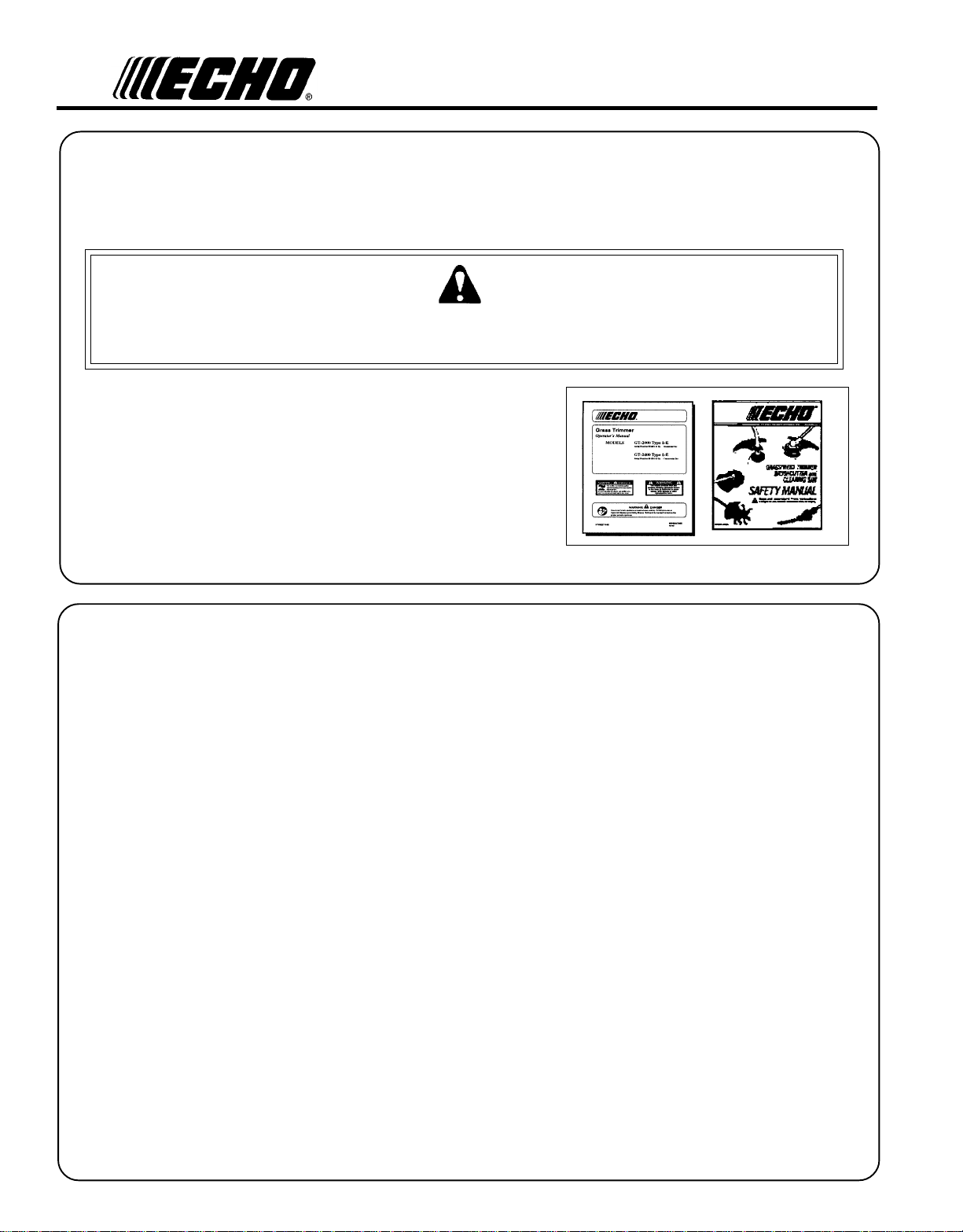
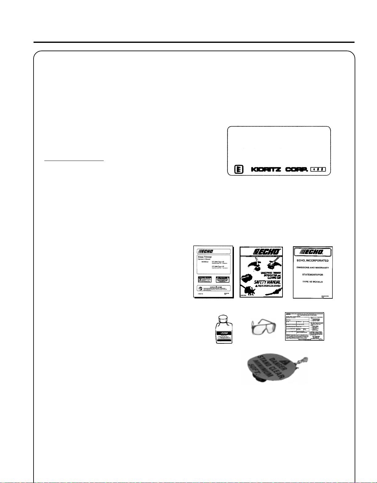
Read rules for safe operation and instructions carefully. ECHO provides an Operator's
Manual and a Safety Manual. Both must be read and understood for proper and safe
operation.
X7532270904
W ARNING DANGER
89869544434
03/01
Page 2
2
INTRODUCTION
Welcome to the ECHO family. This ECHO product was designed and manufactured to provide long life and on-the-jobdependability. Read and understand this manual and the SAFETY MANUAL you found in the same package. You will
find both easy to use and full of helpful operations tips and SAFETY messages.
W ARNING DANGER
Read rules for safe operation and instructions carefully. ECHO provides an Operator's Manual and
a Safety Manual. Both must be read and understood for proper and safe operation.
THE OPERATOR'S MANUAL
contains specifications and information for operation, starting,
stopping, maintenance, storage and assembly specific to this product.
THE SAFETY MANUAL
explains possible hazards involved with the use of Grass Trimmers and
Brush cutters and what measures you should take to make their use
safer.
TABLE OF CONTENTS
Introduction ...............................................................2
Manual Safety Symbols and Important Information ..3
Safety ......................................................................... 3
- Decals .................................................................3
- International Symbols.........................................4
- Equipment ........................................................... 4
- Fuel ..................................................................... 5
- Personal Conditions and Safety Equipment .......5
- Safe Operation .................................................... 7
- Extended Operation/Extreme Conditions ............8
Description ................................................................9
- Emission Control.................................................9
- Contents List ......................................................9
Specifications...........................................................12
Assembly ................................................................. 13
- Plastic Shield.....................................................1 3
- Nylon Head....................................................... 13
- Front (Loop) Handle ......................................... 1 3
Pre-Operation ........................................................... 1 4
- Fuel ................................................................... 1 4
- Equipment Check .............................................. 16
- Determine Operation Area ................................ 1 6
Operation ................................................................. 1 7
- Starting Cold Engine ......................................... 1 7
- Starting Warm Engine....................................... 1 8
CopyRight© 2001 By Echo, Incorporated
All Rights Reserved.
- Stopping Engine ............................................... 1 8
Maintenance ............................................................ 19
- Skill Level .......................................................... 1 9
- Maintenance Intervals ...................................... 19
- Air Filter ............................................................2 0
- Fuel Filter...........................................................2 0
- Spark plug .........................................................2 1
- Cooling System .................................................2 1
- Exhaust System .................................................2 2
- Carburetor Adjustment Emission Models ......... 2 3
- Carburetor Adjustment Non Emission Models .2 4
- Lubrication ........................................................ 2 5
- Nylon Line Replacement (GT-2000) ................... 25
- Nylon Line Replacement (GT-2400) ................... 26
Troubleshooting ......................................................2 8
Storage..................................................................... 2 9
Servicing Information............................................... 32
- Parts.................................................................. 32
- Service .............................................................. 32
- ECHO Customer Assistance ............................. 3 2
- Warranty Card .................................................. 3 2
- Additional or Replacement Manuals ................3 2
Specifications, descriptions and illustrative material in this
literature are as accurate as known at the time of publication, but are subject to change without notice. Illustrations
may include optional equipment and accessories, and may
not include all standard equipment.
Page 3
G
RASS
O
PERATOR'S MANUAL
MANUALSAFETY SYMBOLS AND IMPORTANT INFORMATION
Throughout this manual and on the product itself, you will find safety
alerts and helpful, information messages preceded by symbols or key
words. The following is an explanation of those symbols and key words
and what they mean to you.
This symbol accompanied by the words WARNING and
DANGER calls attention to an act or condition that can
lead to serious personal injury to operator and bystanders.
IMPORTANT The enclosed message
provides information necessary for the
protection of the unit.
T
RIMMER
3
The circle with the slash symbol means whatever is
shown within the circle is prohibited.
SAFETY
DECALS
Locate these safety decals on your unit. The complete unit illustration,
found in the "DESCRIPTION" section, will help you locate them. Make
sure the decals are legible and that you understand and follow the
instructions on them. If a decal cannot be read, a new one can be
ordered from your ECHO dealer. See PARTS ORDERING instructions
for specific information.
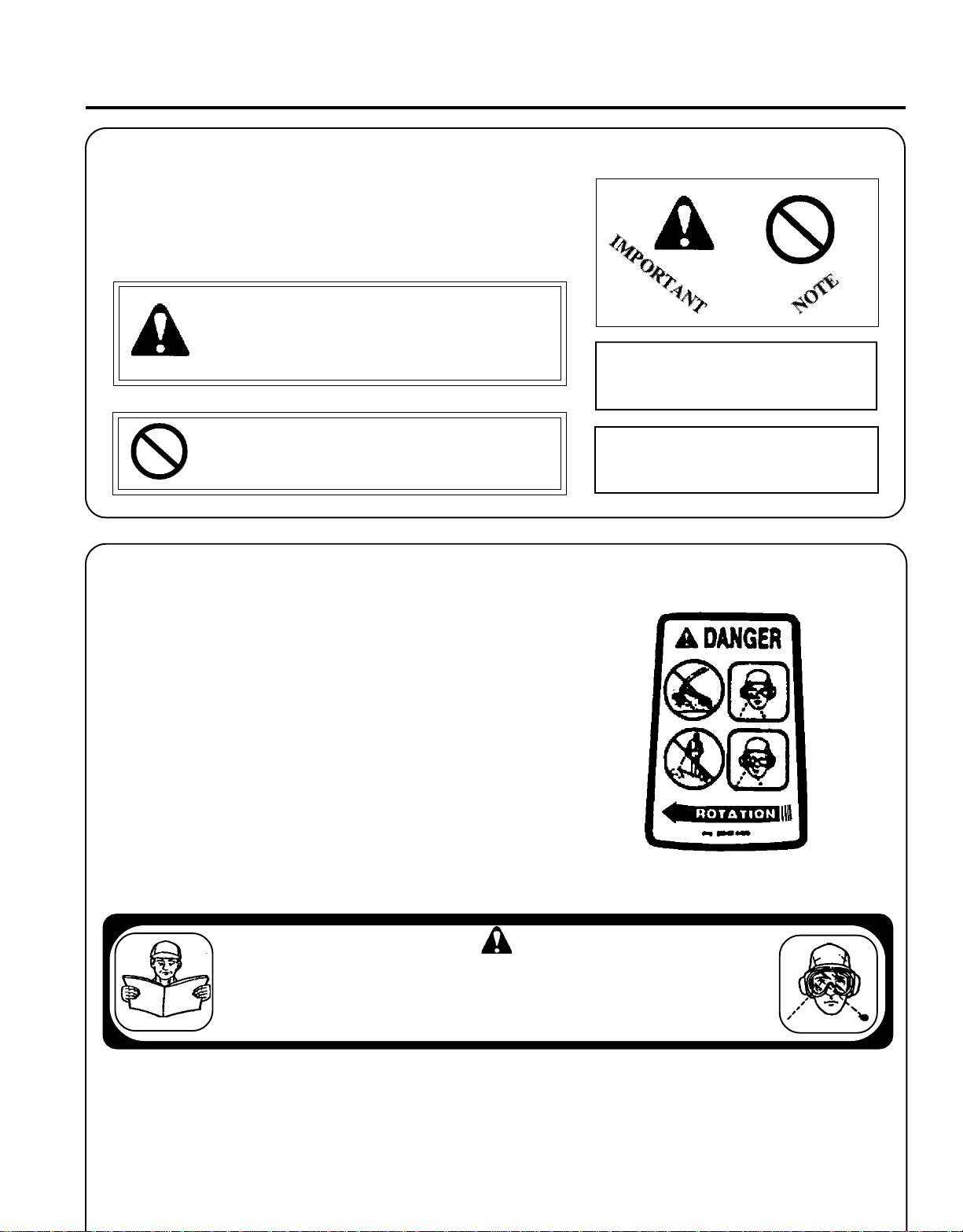
SHAFT DECAL
NOTE This enclosed message provides
tips for use, care and maintenance of the
unit.
Metal Debris
Shield
•This unit can be dangerous and cause serious injury if improperly used. • Operators, helpers and bystanders can be severely in jured by
W ARNING DANGER
thrown objects and must wear specified ANSI Z87.1 eye protection. Blindness or loss of eye can occur. Do not rely on cutter head shield to
protect eyes. Ricochet can occur. •to avoid accidental contact, keep everyone beyond operating area. •To reduce the risk of injury to operator,
helpers & bystanders, read and understand your operator's and safety manuals. For a free copy of the safety Manual, write to ECHO,
INCORPORATED, 400 Oakwood Road, Lake Zurich, IL 60047. •Keep shield and other components in place and in good condition. Do not
use attachments or other parts not approved by ECHO. GT style (non-blade capable) units must not be converted to blade use except MaxiCuts or similar ECHO approved attachments.
Page 4
4
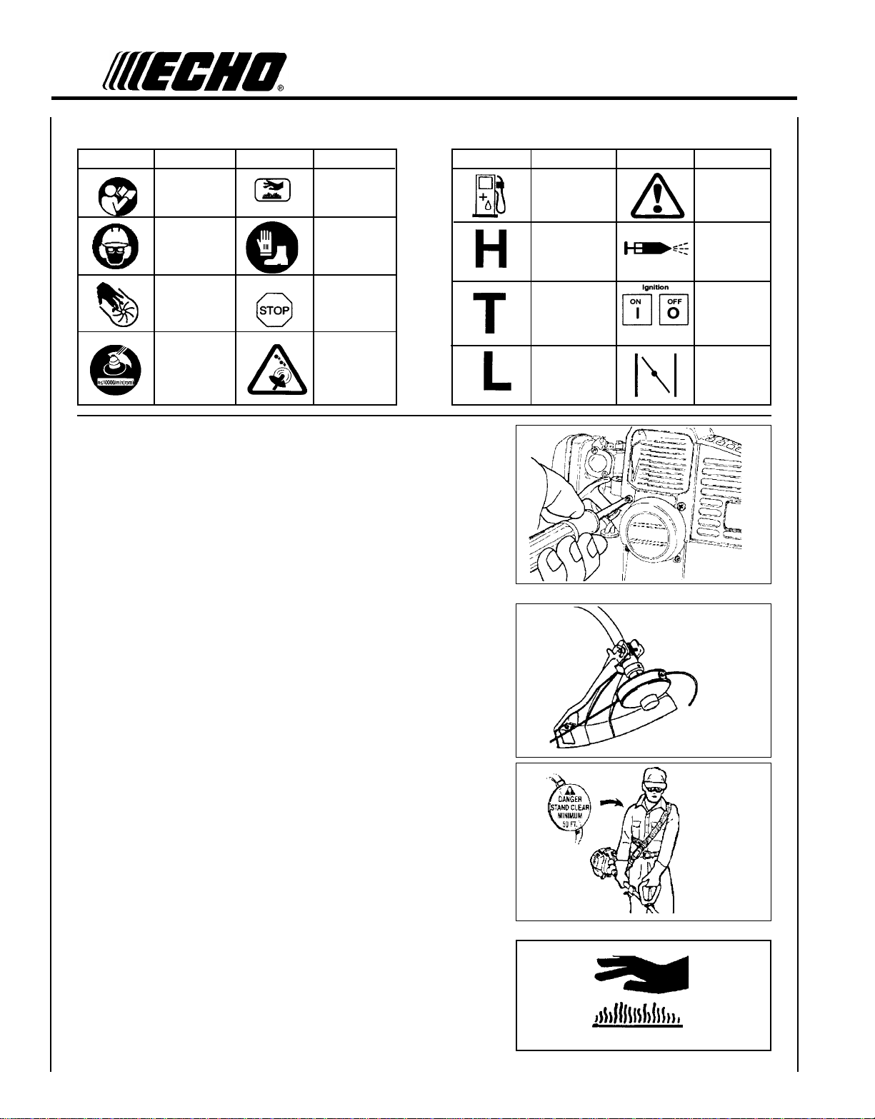
INTERNA TIONAL SYMBOLS
Symbol form/shape
Symbol
description/application
"WARNING, SEE
OPERATOR'S
MANUAL
Symbol form/shape
Symbol
description/application
Hot
Surface
Symbol form/shape
Symbol
description/application
Fuel and oil mixture
Symbol form/shape
Symbol
description/application
WARNING
Wear eyes, ears and
head protection
Finger Severing
Do not exceed
10,000 RPM.
Wear hand and
foot protection
Emergency stop
Beware
- Thrown,
Ricochet
objects
EQUIPMENT
Before operation a complete check of the unit must be performed;
• Check unit for loose/missing nuts, bolts and screws. Tighten and/or
replace as needed.
• Inspect fuel lines, tank and area around carburetor for fuel leaks.
DO NOT operate unit if leaks are found.
• Inspect shield for damage and ensure that the cut-off knife issecurely
in place. Replace if either is damaged or missing.
Carburetor adjustment
- High speed mixture
Carburetor adjustment
- Idle speed
Carburetor adjustment
- Low speed mixture
Primer Bulb
IGNITION
ON/OFF
Engine choke
control.
• Check that the cutting attachment is firmly attached and in safe
operating condition.
• Check that front (loop) handle and optional shoulder/waist harness
are adjusted for safe, comfortable operation. See Assembly for proper
adjustment.
• Have repairs done only by an authorized ECHO Service Dealer.
• Do not use any attachment, accessory or replacement part unless it is
recommended in the Operator's Manual.
Spark Arrestor - Catalytic Muffler/Muffler
• The muffler or catalytic muffler controls the exhaust noise and
emissions. The spark arrestor screen prevents hot, glowing particles
of carbon from leaving the muffler. Make sure the spark arrestor
screen is in good repair and properly seated in the muffler. Keep
exhaust area clear of flammable debris. Avoid contact during and
immediately after operation.
Page 5
FUEL
W ARNING DANGER
Fuel is VERY flammable. Use extreme care when mixing, storing or
handling, otherwise serious personal injury may result.
• Use an approved fuel container.
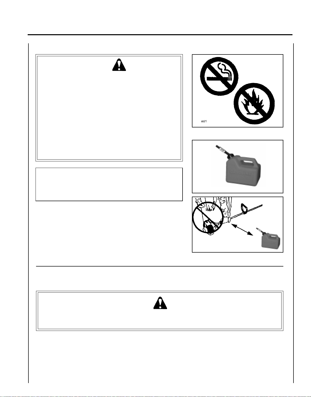
• DO NOT smoke near fuel.
• DO NOT allow flames or sparks near fuel.
• Fuel tanks/cans may be under pressure. Always loosen fuel caps
slowly allowing pressure to equalize.
• NEVER refuel a unit when the engine is HOT!
• NEVER refuel a unit with the engine running.
• DO NOT fill fuel tanks indoors. ALWAYS fill fuel tanks outdoors
over bare ground.
• Securely tighten fuel cap after refueling.
• Inspect for fuel leakage. If fuel leakage is found, do not start or
operate unit until leakage is repaired.
G
RASS
O
PERATOR'S MANUAL
T
RIMMER
5
IMPORTANT
Spilled fuel is a leading cause of hydrocarbon emissions. Some
states may require the use of automatic fuel shut-off containers to
reduce fuel spillage. Contact your ECHO dealer for ordering
information.
After Refueling;
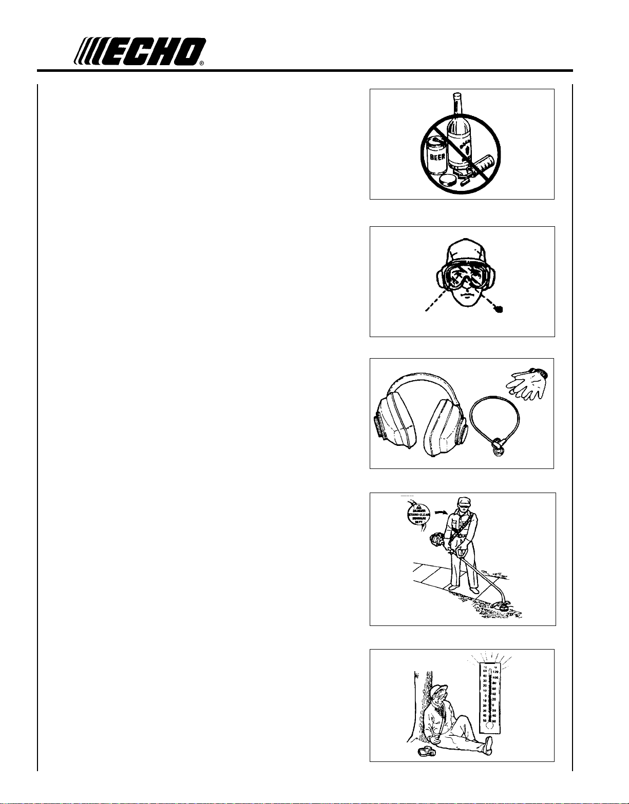
• Wipe any spilled fuel from the unit.
• Move at least 3 m (10 ft.) from refueling location before starting.
After Use;
• DO NOT store a unit with fuel in its tank. Leaks can occur. Return
unused fuel to an approved fuel storage container.
3 m (10 ft.)
PERSONAL CONDITION AND SAFETY EQUIPMENT
W ARNING DANGER
Trimmer/Brush Cutter users risk injury to themselves and others if the trimmer/brush cutter is used improperly and or
safety precautions are not followed. Proper clothing and safety gear must be worn when operating a trimmer.
Page 6
6
Physical Condition --
Your judgment and physical dexterity may not be good:
• if you are tired or sick,
• if you are taking medication,
• if you have taken alcohol or drugs.
Operate unit only if you are physically and mentally well.
Eye Protection --
Wear eye protection that meets ANSI Z87.1 or CE requirements
whenever you operate the trimmer.
Hand Protection --
Wear no-slip, heavy duty work gloves to improve your grip on the
Trimmer/Brush Cutter handles. Gloves also reduce the transmission of
machine vibration to your hands.
Hearing Protection --
ECHO recommends wearing hearing protection whenever unit is used.
Proper Clothing --
Wear snug fitting, durable clothing;
• Pants should have long legs, shirts with long sleeves.
• DO NOT WEAR SHORTS,
• DO NOT WEAR TIES, SCARVES, JEWELRY.
Wear sturdy work shoes with non-skid soles;
• DO NOT WEAR OPEN TOED SHOES,
• DO NOT OPERATE UNIT BAREFOOTED.
Hot Humid Weather --
Heavy protective clothing can increase operator fatigue which may lead
to heat stroke. Schedule heavy work for early morning or late afternoon
hours when temperatures are cooler.
Page 7
SAFE OPERATION
G
RASS
O
PERATOR'S MANUAL
T
RIMMER
7
Determine Operation Area
• Provide all operators of this equipment with the Operator's Manual
and instructions for safe operation.
• Review the area to be trimmed. Look for hazards that could contribute
to unsafe conditions.
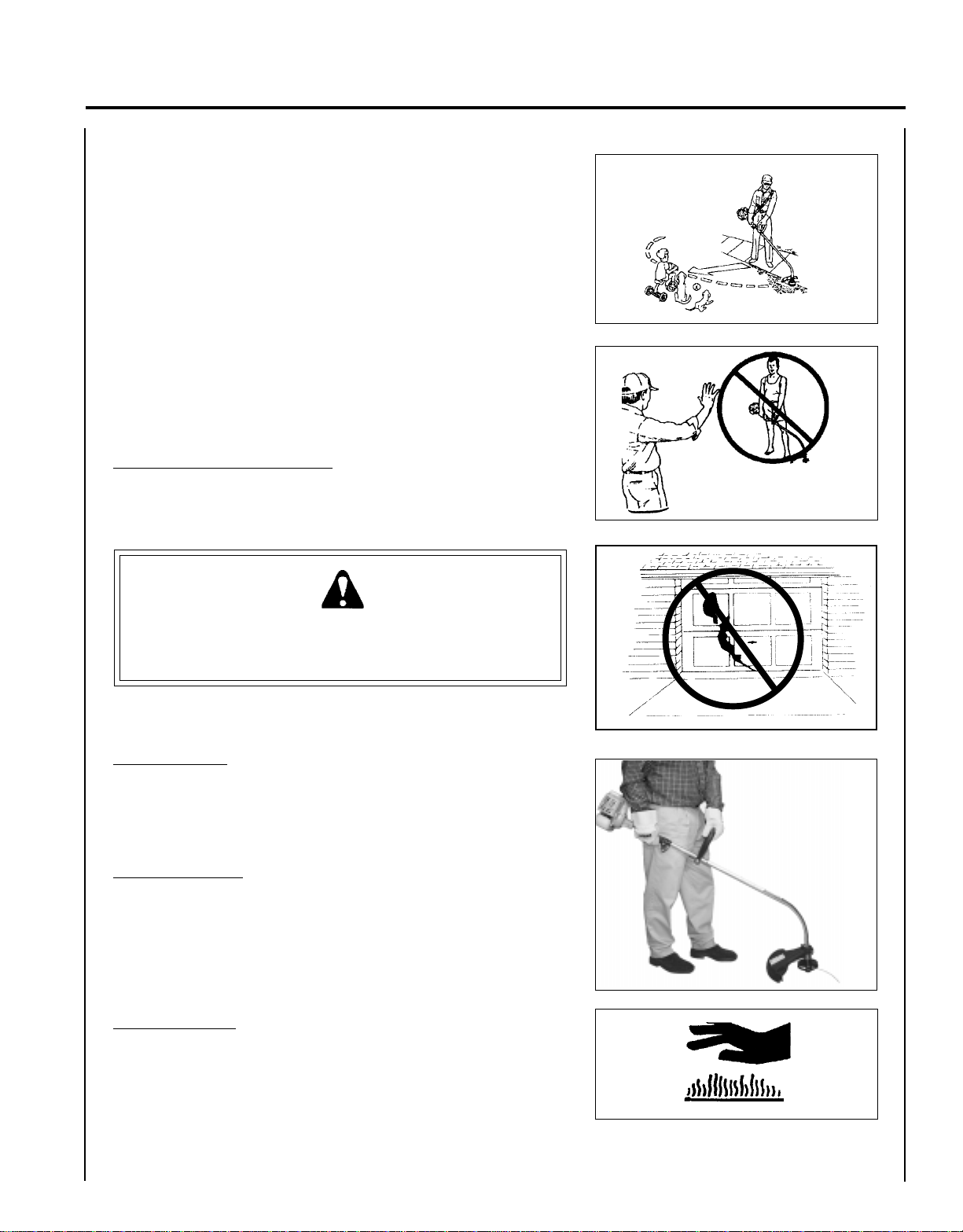
• Spectators and fellow workers must be warned, and children and
animals prevented from coming nearer than 15 m (50 ft.) while
the trimmer is in use.
Operation
Use Proper Clothing & Equipment
• Before starting the unit, equip yourself and any other person
working within the 15 m (50 ft.) Safety Zone with the required
Protective Equipment and clothing.
W ARNING DANGER
Do not operate this product indoors or in inadequately ventilated
areas. Engine exhaust contains poisonous emissions and can cause
serious injury or death.
15 m (50 ft.)
Keep A Firm Grip
• Hold the front and rear handles with both hands with thumbs and
fingers encircling the handles
Keep A Solid Stance
• Maintain footing and balance at all times. Do not stand on slippery,
uneven or unstable surfaces. Do not work in odd positions or on
ladders. Do not over reach.
Avoid Hot Surfaces
• During operation, the complete unit, especially the drive shaft
housing and the bearing housing may become very hot, too hot to
touch. Avoid contact during and immediately after operation.
Page 8
8
EXTENDED OPERATION/EXTREME CONDITIONS
Vibration and Cold --
It is believed that a condition called Raynaud’s Phenomenon, which
affects the fingers of certain individuals may be brought about by
exposure to vibration and cold. Exposure to vibration and cold may
cause tingling and burning sensations followed by loss of color and
numbness in the fingers. The following precautions are strongly
recommended because the minimum exposure which might trigger the
ailment is unknown.
• Keep your body warm, especially the head, neck, feet, ankles, hands
and wrists.
• Maintain good blood circulation by performing vigorous arm exercises during frequent work breaks and also by not smoking.
• Limit the hours of operation. Try to fill each day with jobs where
operating the trimmer or other hand-held power equipment is not
required.
• If you experience discomfort, redness and swelling of the fingers
followed by whitening and loss of feeling, consult your physician
before further exposing yourself to cold and vibration.
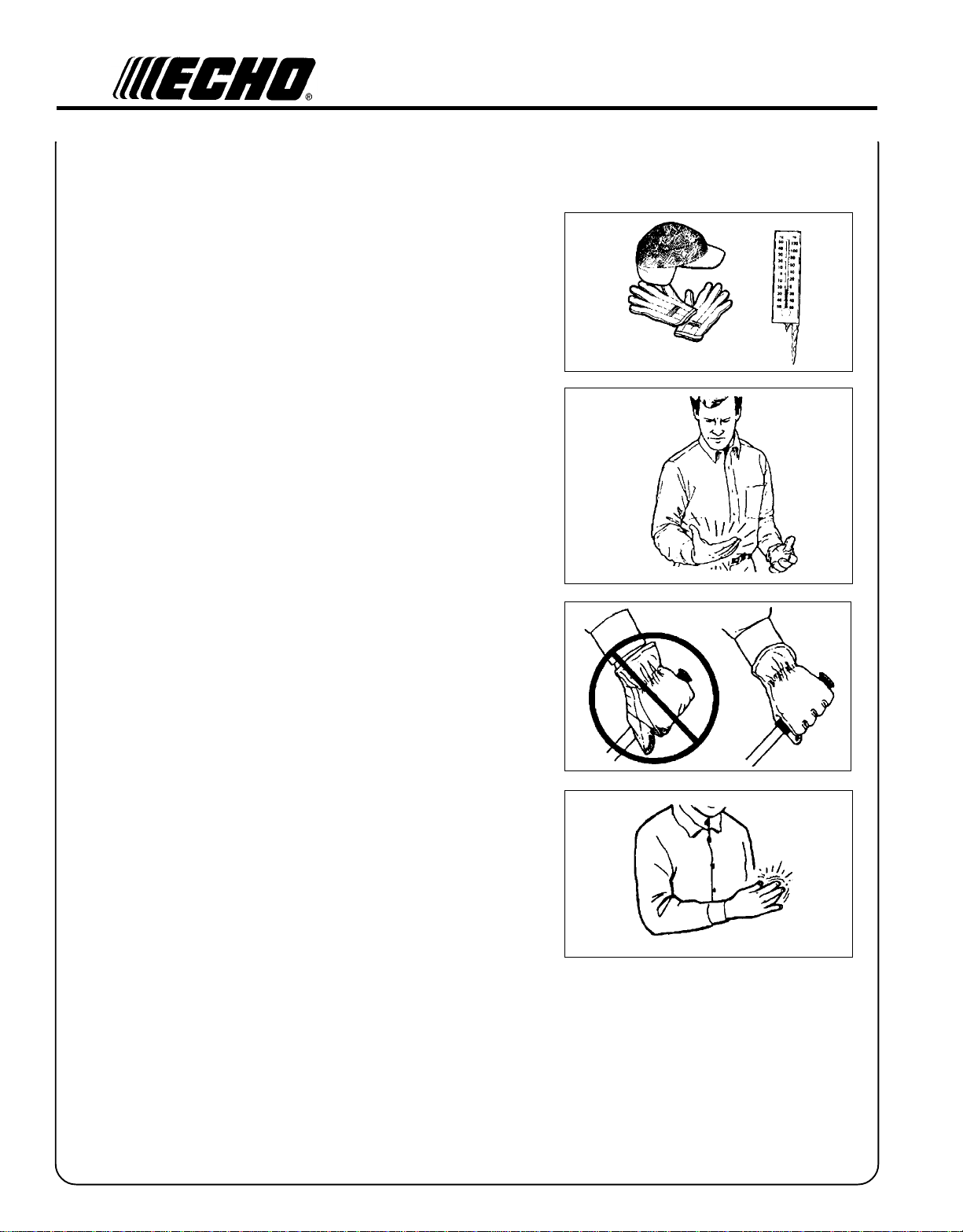
Repetitive Stress Injuries --
It is believed that overusing the muscles and tendons of the fingers,
hands, arms and shoulders may cause soreness, swelling, numbness,
weakness and extreme pain in those areas. Certain repetitive hand
activities may put you at a high risk for developing a Repetitive Stress
Injury (RSI). An extreme RSI condition is Carpal Tunnel Syndrome
(CTS), which could occur when your wrist swells and squeezes a vital
nerve that runs through the area. Some believe that prolonged exposure
to vibration may contribute to CTS. CTS can cause severe pain for
months or even years. To reduce the risk of RSI/CTS, do the following:
• Avoid using your wrist in a bent, extended or twisted position.
Instead try to maintain a straight wrist position. Also, when grasping,
use your whole hand, not just the thumb and index finger.
• Take periodic breaks to minimize repetition and rest your hands.
• Reduce the speed & force in which you do the repetitive movement.
• Do exercises to strengthen the hand and arm muscles.
• Immediately stop using all power equipment and consult a doctor if
you feel tingling, numbness or pain in the fingers, hands, wrists or
arms. The sooner RSI/CTS is diagnosed, the more likely permanent
nerve and muscle damage can be prevented.
Page 9
G
RASS
O
PERATOR'S MANUAL
T
RIMMER
DESCRIPTION
The ECHO product you purchased has been factory pre-assembled for your convenience. Due to packaging restrictions,
shield installation and positioning of the front handle are necessary.
After opening the carton, check for damage. Immediately notify your retailer or ECHO Dealer of damaged or missing
parts. Use the contents list to check for missing parts.
9
EMISSION CONTROL --
The emission control system for this engine is EM (Engine
Modification).
Emission Control Label located on Engine
(EXAMPLE ONLY, information on label varies by FAMILY).
CONTENTS LIST
____ 1 - Trimmer Assembly
____ - Power Head
____ - Drive Shaft Assembly
____ 1 - Plastic Bag (Co-Pack)
____ - Operator's Manual
____ - Safety Manual
____ - Shield Assembly
____ - Hardware Bag
____ -1, 1/4-20 bolt
____ -1, 1/4-20 wing nut
____ -1, 1/4-20 flat washer
____ - Shoulder Strap, GT-2400 only
____ - Warranty Card & Limited Warranty
____ - Safety Glasses
____ - Oil 2 Stroke
IMPORTANT ENGINE INFORMATION
ENGINE FAMILY : TEH021UB24RA
DISPLACEMENT : 21.2cc
THIS ENGINE MEETS U.S. EPA PHI AND 1995 - 1999
CALIFORNIA EMISSION REGULATIONS FOR ULGE
ENGINES. REFER TO OWNER’S MANUAL FOR
MAINTENANCE SPECIFICATIONS AND ADJUSTMENTS.
IMPORTANT
This spark ignition system complies with Canadian ICES-002
Page 10
10
13
17
21
20
14
15
16
1
6
7
2
19
18
5
4
22
8
3
9
10
11
12
Page 11

G
RASS
O
PERATOR'S MANUAL
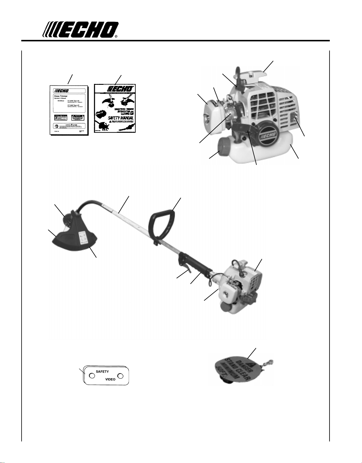
1. OPERATOR'S MANUAL - Included in plastic bag (co-pack). Read before operation and keep in a safe place for
future reference, i.e., operation, maintenance, storage and specifications.
2. SAFETY MANUAL - Included in plastic bag (co-pack). Read before operation and keep in a safe place for future
reference to learn proper, safe operating techniques.
3. POWER HEAD - Factory Assembled to the Driveshaft assembly. Includes the Engine, Clutch, Fuel System, Ignition
System and Recoil Starter.
4. FRONT HANDLE - The Front (loop) handle is factory assembled to the Drive Shaft assembly but must be re-
positioned for proper cutting attitude and operator comfort.
5. DRIVESHAFT ASSEMBLY - Factory Assembled to the Power Head. Includes the Rear (right hand) Handle Assem-
bly, Bearing Housing Assembly, Throttle Trigger, Front (loop, left hand) Handle Assembly, Flexible Drive Cable and
Safety Decals.
6. NYLON CUTTER HEAD - Contains replaceable nylon trimming line that advances when the trimmer head is tapped
against the ground while the head is turning at normal operating speed.
7. DEBRIS SHIELD ASSEMBLY - Included in plastic bag (co-pack). MUST be installed on unit before use, see
Assembly Instructions. Shield assembly includes the Cut-Off Knife and Safety Decal. Mounts on the Bearing
Housing Assembly just above the cutting attachment. Helps protect the operator by deflecting debris produced
during the trimming operation.
8. CUT-OFF KNIFE - Trims line to the correct length (5 in.). If trimmer is operated without a cut-off knife the line will
become too long - more than (5 in.) - the operating speed will slow, the engine overheat and performance will suffer.
9. THROTTLE TRIGGER - Spring loaded to return to idle when released. During acceleration, press trigger gradually
for best operating technique.
10. GRIP - Rear (right hand) handle.
11. STOP SWITCH -
GT-2000 - "TOGGLE SWITCH" mounted on the engine. Move switch UP to RUN, DOWN to STOP.
GT-2400 - "SLIDE SWITCH" mounted on top of the Throttle Trigger Housing. Move switch FORWARD to RUN,
BACK to STOP.
12. SHOULDER HARNESS- Standard, GT-2400, optional, GT-2000. An adjustable strap that suspends the unit from the
operator.
13. ARM REST - Provides arm rest during operation and protects arm from hot engine.
14. MUFFLER SPARK ARRESTOR - The muffler controls the exhaust noise while the spark arrestor prevents hot
particles of carbon from leaving leaving the muffler where they could possibly start a fire.
15. FUEL TANK - Contains fuel and fuel filter.
16. RECOIL STARTER HANDLE - Pull handle slowly until recoil starter engages, then quickly and firmly. When engine
starts, return handle slowly. DO NOT let handle snap back or damage to unit will occur.
17. FUEL TANK CAP - Cover and seals fuel tank opening.
18. PRIMER BULB -Pumping primer bulb before starting engine draws fresh fuel from the fuel tank priming the carbure-
tor for starting. Pump primer bulb until fuel is visible and flows freely in the clear fuel tank return line. Pump bulb an
additional 4 or 5 times.
19. AIR CLEANER - Contains replaceable filter element.
20. CHOKE - Located above the air cleaner housing. Controls operation of choke. Move choke to starting position
(Close Choke) and back to run position (Open Choke).
21. SPARK PLUG - Provides spark to ignite fuel mixture.
22. SAFETY VIDEO - (Not included with unit) P/N 99922202540 English version only is available at a cost of $5.00 from
ECHO, INC. or any authorized ECHO dealer. The video overviews safety precautions and proper operating techniques and is supplemental to the Safety Manual. Read and understand the Safety Manual for complete information
on safe operation.
T
RIMMER
11
Page 12

12
SPECIFICATIONS
LEDOM0002-TG0042-TG
htgneL).ni1.55(mm0041).ni1.95(mm0051
htdiW ).ni0.31(mm033
thgieH ).ni2.41(mm063
epyTenignE enigneenilosagrednilycelgnis,ekorts-owt,deloocriA
eroB).ni862.1(mm2.23).ni43.1(mm0.43
daeHrettuC/w)yrd(thgieW).bl3.9(gk2.4).bl9.9(gk5.4
ekortS
tnemecalpsiD).ni.uc92.1(cc2.12).ni.uc44.1(cc6.32
tsuahxE relffuMrotserrAkrapS
roterubraCegrup/wU1CledommgarhpaidamaZegrup/wledomTWorblaW
metsySnoitingI egrahcsidroticapac,otengamleehwylF
gulPkrapS).ni620.0(mm56.0(A7-RMPBKGN ).ni620.0(mm56.0(Y7-JCRnoipmahC
leuF )liOekorts-owTdnaenilosaG(dexiM
oitaRliO/leuF lioenignedeloocriaekorts-owt,ecnamrofrePhgiHOHCE1:05
enilosaG
liO lioenignedeloocriaekorts-owt,ecnamrofrePhgiHOHCE1:05
yticapaCknaTleuF
metsySretratSlioceR retratSlioceRcitamotuA
hctulC epyTlagufirtneC
).ni40.1(mm0.62
,lohoclalyhtemgniniatnocleufesuTONOD.dedaelnuenatcO98
.EBTM%51rolohoclalyhte%01nahterom
).zo.lfSU5.31(.til4.0
tfahSevirD tfahSxelF"4/1
noitceriDgnitatoR potmorfdeweivesiwkcolC
daeHrettuC ).tf02(m5.6yticapacenil.ni080.htiw)eniL-2(daehenilnolyN
eldnaHtnorF pirG-thgiR,pooL-D-tfeL
ssenraHredluohS10200244999lanoitpOdradnatS
)MPR(deepSeldI MPR0023-0042
deepSelttorhTnepOediW
eniLnolyNhtiw).T.O.W(
)MPR(daeH
MPR0057-0086
Page 13
ASSEMBLY
Tools Required: Locking Tool
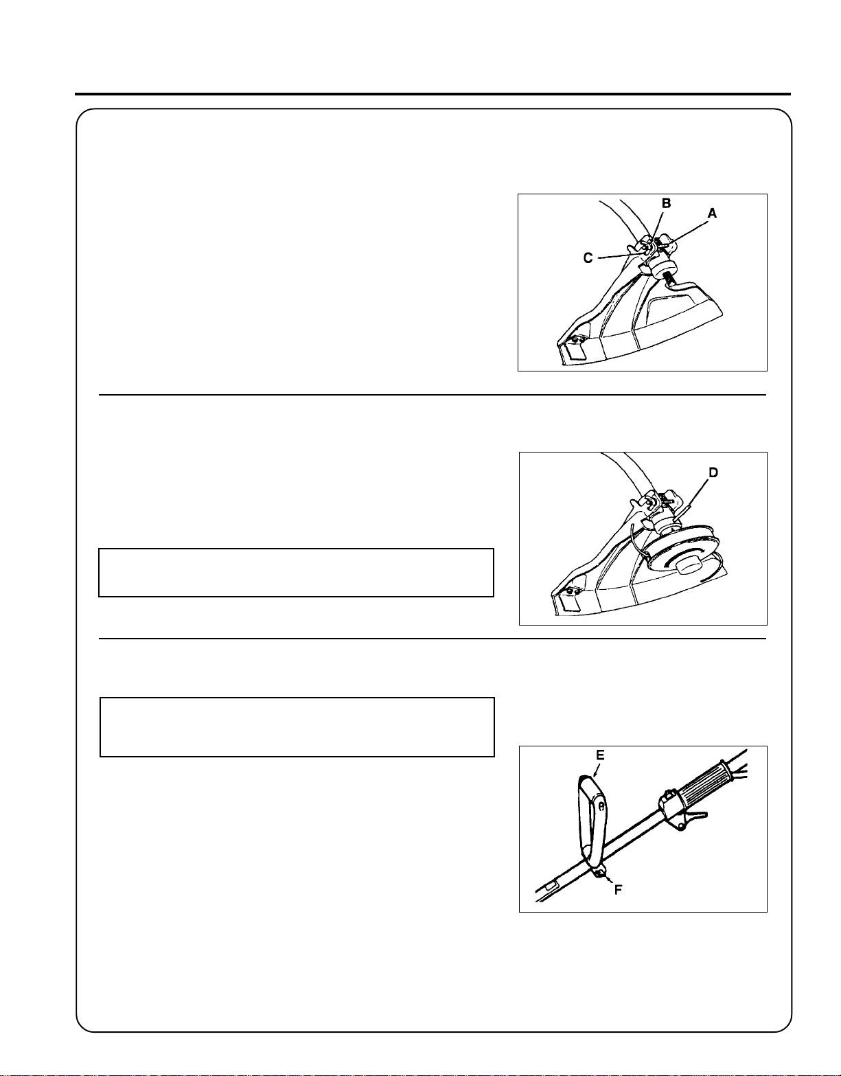
PLASTIC SHIELD
1. Snap the shield over the bearing housing.
2 . Install bolt (A), washer (B) and wing nut (C).
NYLON LINE HEAD
G
RASS
O
PERATOR'S MANUAL
T
RIMMER
13
1 . Align locating hole in locating plate with hole in bearing housing.
2 . Insert 1/8" dia. locking tool (D) (not included with unit) and thread
cutting attachment onto shaft clockwise until head is tight.
IMPORTANT
Remember to remove the locking tool.
FRONT (LOOP) HANDLE
NOTE
Front handle is pre-installed. Re-positioning and tightening is all
that is required.
1 . Position front handle (E) in comfortable operating position and
tighten wing nut (F). The cutting attachment should be 5cm- 7.5cm
(2 in. -3 in.) above the ground and as level as possible.
HARNESS (GT-2400 ONLY)
1. Put on harness and attach unit to harness.
2 . Slide harness clamp up or down until unit balances with cutting
head approximately 2"- 3" from the ground.
3. Tighten harness clamp screw.
Page 14
14
PRE - OPERA TION
FUEL
Fuel Requirements
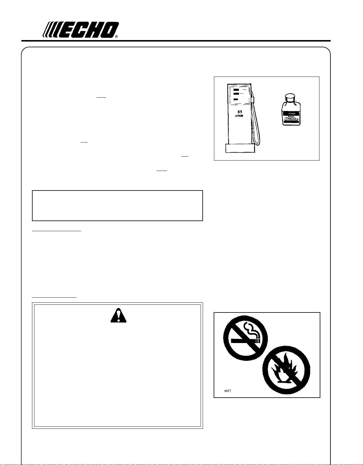
Gasoline - Use 89 Octane [ ] (mid grade or higher) gasoline known
to be good quality. Gasoline may contain up to 15% MTBE (methyl
tertiary-butyl ether). Gasohol containing methyl (wood) alcohol is NOT
approved.
Two Stroke Oil - A two-stroke engine oil meeting ISO-L-EGD (ISO/CD
13738) and J.A.S.O. FC Standards, must be used. Echo brand Premium
50:1 oil meets these standards. Engine problems due to inadequate
lubrication caused by failure to use an ISO-L-EGD and J.A.S.O. FC
certified oil, such as Echo Premium 50:1 Two-stroke Oil, will void the
two-stroke engine warranty. (Emission related parts only are covered
for two years, regardless of two-stroke oil used, per the statement listed
in the EPA Phase I/California Emission Defect Warranty Explanation.)
IMPORTANT
Echo Premium 2-Stroke Oil may be mixed at 50:1 ratio for application in all Echo engines sold in the past regardless of ratio specified in those manuals.
R + M
2
Mixing Instructions
1 . Fill an approved fuel container with half of the required amount of
gasoline.
2 . Add 2-stroke oil to gasoline.
3 . Close container and shake to mix oil with gasoline.
4 . Add remaining gasoline and remix.
5 . Install fuel container cap and wipe any spilled fuel from container
and surrounding area.
Handling Fuel
W ARNING DANGER
Fuel is VERY flammable. Use extreme care when mixing, storing or
handling, or serious personal injury may result.
• Use an approved fuel container.
• DO NOT smoke near fuel.
• DO NOT allow flames or sparks near fuel.
• Fuel tanks/cans may be under pressure. Always loosen fuel caps
slowly allowing pressure to equalize.
• NEVER refuel a unit when the engine is HOT!
• NEVER refuel a unit with the engine running.
• DO NOT fill fuel tanks indoors. ALWAYS fill fuel tanks outdoors
over bare ground.
• Securely tighten fuel cap after refueling.
• Inspect for fuel leakage. If fuel leakage is found, do not start or
operate unit until leakage is repaired.
Page 15

IMPORTANT
Spilled fuel is a leading cause of hydrocarbon emissions. Some
states may require the use of automatic fuel shut-off containers to
reduce fuel spillage. Contact your ECHO dealer for ordering
information.
After refueling;
• Wipe any spilled fuel from the unit.
• Move at least 3 m (10 ft.) from refueling location before starting the
engine.
After use;
• DO NOT store a unit with fuel in its tank. Leaks can occur.
Return unused fuel to an approved fuel storage container.
Storage -
Fuel storage laws vary by locality. Contact your local government for
the laws affecting your area. As a precaution, store fuel in an approved,
air tight container. Store in a well ventilated, unoccupied building, away
from sparks and flames. Do not store fuel longer than 30 days.
IMPORTANT
Stored fuel ages. Do not mix more fuel than you expect to use in
thirty (30) days, ninety (90) days when a fuel stabilizer is added.
G
RASS
O
PERATOR'S MANUAL
3 m (10 ft.)
T
RIMMER
SMTWTFS
1234567
8 9 10 11 12 13 14
15 16 17 18 19 20 21
22 23 24 25 26 27 28
29 30 31
15
IMPORTANT
Stored two-stroke fuel may separate. ALWAYS shake fuel
container thoroughly before each use.
Page 16

16
EQUIPMENT CHECK
Before operation a complete check of the unit must be performed;
• Check unit for loose/missing nuts, bolts and screws. Tighten and/or
replace as needed.
• Inspect fuel lines, tank and area around carburetor for fuel lieaks. DO
NOT operate unit if leaks are found.
• Inspect shield for damage and ensure that the cut-off knife is securely
in place. Replace if either is damaged or missing.
• Check that the cutting attachment is firmly attached and in safe
operating condition.
• Check that front (loop) handle and shoulder strap/ or shoulder/waist
harness are adjusted for safe, comfortable operation. See Assembly
for proper adjustment.
• Have repairs done only by an authorized ECHO Service Dealer.
• Do not use any attachment, accessory or replacement part unless it is
recommended in the Operator's Manual.
DETERMINE OPERATION AREA
• Review the area to be trimmed. Look for hazards that could contribute
to unsafe conditions.
• Spectators and fellow workers must be warned, and children and
animals prevented from coming nearer than 15 m (50 ft.) while the
trimmer is in use.
15 m (50 ft.)
Page 17

OPERATION
• Provide all operators of this equipment with the Operator's Manual
and Instructions for safe use.
• Before starting the unit, equip yourself and any other person working
within the 15 m (50 ft.) Safety Zone with the required Protective
Equipment and clothing.
• During operation, the complete unit, especially the drive shaft
housing and the bearing housing may become very hot, too hot to
touch. Avoid contact during and immediately after operation.
ST ARTING COLD ENGINE
G
RASS
O
PERATOR'S MANUAL
T
RIMMER
17
W ARNING DANGER
The cutting attachment should not rotate at idle. If attachment
rotates, readjust carburetor according to "Carburetor Adjustment"
instructions in this manual or see your ECHO Dealer, otherwise
serious personal injury may result.
1 . Stop Switch - Start/Run.
Move stop switch button (A) away from the STOP position.
2 . Choke Lever - Cold Start.
Move choke (B) to “Cold Start” Position.
3 . Primer - Pump Bulb
Pump primer bulb (C) until fuel is visible and flows freely in the
clear fuel tank return line. Pump bulb an additional 4 or 5 times.
W ARNING DANGER
Inspect starting area for hazards such as rocks, glass, debris etc.
which could be thrown by the cutting attachment when starting.
Keep helpers and bystanders at least 15m (50 feet) from starting
area, otherwise serious personal injury may result.
4 . Lay the trimmer on a flat clear area. Firmly grasp throttle grip with
left hand and fully depress throttle trigger to wide open position.
Rapidly pull starter handle/rope (D) until engine fires (maximum five
[5] pulls).
D
Page 18

18
5 . After engine fires or five (5) pulls, move choke lever to “Run”
position. Hold throttle trigger fully depressed and pull starter
handle/rope until engine starts and runs. Release throttle trigger
and allow unit to warm up at idle for several minutes.
GT-2000
NOTE
If engine does not start with choke in “Run” position after 5 pulls,
repeat instructions.
6 . After engine warm up, gradually depress throttle trigger to increase
engine RPM to operating speed.
STARTING WARM ENGINE
W ARNING DANGER
The cutting attachment should not rotate at idle. If attachment
rotates, readjust carburetor according to "Carburetor Adjustment"
instructions in this manual or see your ECHO Dealer, otherwise
serious personal injury may result.
1 . Stop Switch - Start/Run. Move stop switch button (A) away from
the STOP position.
2 . Start - Pull Rope. Lay the trimmer on a flat clear area and pull
the starter handle (D) until the engine fires.
GT-2400
NOTE
If engine does not start after 5 pulls, use Cold Start Procedure.
STOPPING ENGINE
1 . Release Throttle. Allow engine to idle for a minute.
2. Stop Switch - Stop. Move stop switch button (A) backward to
STOP position.
W ARNING DANGER
If engine does not stop when stop switch is moved to STOP
position, close choke - COLD START position - to stall engine.
Have your ECHO dealer repair stop switch before using trimmer
again.
NOTE
Refer to the Grass Trimmer / Brush Cutter Safety Manual for proper
and safe trimming techniques.
D
Page 19

G
RASS
O
PERATOR'S MANUAL
T
RIMMER
19
MAINTENANCE
W ARNING DANGER
Do not perform maintenance on engine or muffler until engine and muffler are completely cool, otherwise serious
personal injury may result.
Your ECHO trimmer is designed to provide many hours of trouble free service. Regular scheduled maintenance will help
your trimmer achieve that goal. If you are unsure or are not equipped with the necessary tools, you may want to take your
unit to an ECHO Service Dealer for maintenance. To help you decide whether you want to DO-IT-YOURSELF or have the
ECHO Dealer do it, each maintenance task has been graded. If the task is not listed see your Echo dealer for repairs.
SKILL LEVEL
Level 1 = Easy to do. Most required tools come with unit.
Level 2 = Moderate difficulty. Some specialized tools may be required.
Level 3 = Experience required. Specialized tools are required.
ECHO offers REPOWER Maintenance Kits and Parts to make your maintenance job easier. Just below each task heading
are listed the various part numbers required for that task. See your ECHO dealer for these parts.
MAINTENANCE INTERVALS
metsyS/tnenopmoCerudecorPecnanetniaM
retliFriAecalpeR/tcepsnI
reniartSleuFecalpeR/tcepsnI
eniLleuFecalpeR/tcepsnI
roterubraCecalpeR/naelC/tcepsnI
metsySekohCecalpeR/naelC/tcepsnI
metsySgnilooCnaelC/tcepsnI
krapSrelffuM
rotserrA
xelF(tfahSevirD
)sledoMelbaC
gnisuoHraeGesaerG
epoRretratSnaelC/tcepsnI
skaeLleuFriapeR/tcepsnI
gulPkrapSecalpeR/naelC
royliaD
erofeB
esU
C/I*R
II
C/I
C/I
naelC/tcepsnI
esaerG
I
II
yrevE
leufeR
shtnoM3
09ro
sruoH
IR
C/I
)2(I
I
C/I*R
shtnoM6
072ro
sruoH
C/I)1(R
ylraeY
ylppA)2(OHCE
stloB/stuN/swercSecalpeR/nethgiT/tcepsnI
TNATROPMI
.ecnanetniam
®
I
naelC=C/ecalpeR=R/tcepsnI=I
deriuqerfoycneuqerfehtenimretedlliwecneirepxeruoydnaesulautcA.mumixameranwohsslavretniemiT
MT
EBUL
.stiKdliubeRsedulcnigninaelC.deriuqer
.esufosruoh52yreve
.noitcepsnignirudraewroegamadfognidnifehtnodesaberaecalperotsnoitadnemmocerllA*
sishtnom6yrevegninaelc,esuremusnoCroF.ylraeyesulaicremmocrofderiuqereblliwtnemecalpeR)1(
Page 20

20
AIR FILTER
Level 1.
Tools required: Cleaning brush, 25 - 50 mm (1 or 2 in.) medium bristle
paint brush.
Parts required: Air Filter P/N 13031054130
1. Close choke (Cold Start Position). This prevents dirt from entering
the carburetor throat when the air filter is removed. Brush accumulated dirt from the air cleaner area.
2 . Remove the air cleaner cover. Clean and inspect the element for
damage. If element is fuel soaked and very dirty, replace.
3 . If element can be cleaned and reused, be certain it:
-still fits the cavity in the air cleaner cover.
-is installed with the original side out.
NOTE
Carburetor adjustment may be needed after air filter cleaning/
replacement. See Carburetor Adjustment Section.
FUEL FILTER
Level 1.
Tools required: Fuel line hook, 203-254 mm (8-10 in.) length of wire with
one end bent into a hook. Clean rag, funnel, and an approved fuel
container.
Parts required: Fuel Filter P/N 13120507320
W ARNING DANGER
Fuel is VERY flammable. Use extreme care when mixing, storing or
handling.
1 . Use a clean rag to remove loose dirt from around fuel cap and
empty fuel tank.
2 . Use the “fuel line hook” to pull the fuel line and filter from the tank.
3 . Remove the filter from the line and install the new filter.
Page 21

SP ARK PLUG
Level 2.
Tools Required: Spark Plug socket wrench and screw driver, Feeler
gauge. Preferably a wire gauge.
Parts Required: Spark Plug, GT-2000 NGK BPMR-7A
GT-2400 CHAMPION RCJ-7Y
1 . Remove spark plug and check for fouling, worn and rounded center
electrode.
2 . Clean the plug or replace with a new one. DO NOT sand blast to
clean. Remaining sand will damage engine.
3. Adjust spark plug gap by bending outer electrode.
4 . Tighten spark plug to 145-155 kg/cm (125-135 in. lb.).
G
RASS
O
PERATOR'S MANUAL
0.65 mm
(0.026 in.)
T
RIMMER
21
COOLING SYSTEMS CLEANING
Level 2.
Tools required: Cross Head Screwdriver, 3 mm Hexagon wrench,
Pointed Wood Stick, Cleaning Brush, 25 - 50 mm (1 or 2 in.) medium
bristle paint brush.
Parts Required: None.
IMPORTANT
To maintain proper engine operating temperatures, cooling air must
pass freely through the cylinder fin area. This flow of air carries
combustion heat away from the engine.
Overheating and engine seizure can occur when:
• Air intakes are blocked, preventing cooling air from reaching the
cylinder.
• Dust and grass build up on the outside of the cylinder. This build up
insulates the engine and prevents the heat from leaving.
Removal of cooling passage blockages or cleaning of cooling fins is
considered “Normal Maintenance”. Any failure attributed to lack of
maintenance is not warranted.
1 . Remove spark plug lead and throttle linkage end from the carbure-
tor swivel.
2. Remove the four screws that retain the cover. Two at the top of the
Recoil Starter, two on either side of the front. Lift the cover from the
engine and lay to the front of the trimmer.
Page 22

22
NOTE
The throttle linkage remains assembled to the cover and the spark
plug lead and grommet remain installed.
IMPORTANT
DO NOT use a metal scraper to remove dirt from the cylinder fins.
3 . Use the wooden stick or brush to remove dirt from the cylinder fins.
4 . Remove grass and leaves from the grid between the starter and fuel
tank.
5 . When installing the cover, be certain the tab of the metal deflector
shield is in the slot of the cover.
EXHAUST SYSTEM
Spark Arrestor Screen
Level 2.
Tools Required: Cross Head Screwdriver. Soft metal brush.
Parts Required: Screen P/N 14586240630, Gasket Lid P/N 14586642031
1 . Remove screen cover (A), holder (B) and gasket (C) from muffler
body.
2 . Clean carbon deposits from screen (D) and muffler components.
3 . Replace screen if it is cracked, plugged or has holes burned
through.
C
D
B
A
Page 23

CARBURETOR ADJUSTMENT
Emission Models (with limiter caps)
Level 2.
Tools required: Screwdriver, Tachometer (ECHO P/N 99051130017).
Parts required: None.
NOTE
Every unit is run at the factory and the carburetor is set in compliance with EPA Phase 1 and California Emission Regulations. In
addition, the carburetor is equipped with HI and LO needle
adjustment limiters that prevent settings outside acceptable limits.
1 . Before adjusting the carburetor, clean or replace the air filter and
spark arrester screen.
2. Start engine and run for several minutes to reach operating
temperature.
G
RASS
O
PERATOR'S MANUAL
T
RIMMER
23
3 . Stop engine. Turn HI speed needle (A) CCW (counter clockwise) to
stop. Turn LO speed needle (B) midway between full CCW and CW
(clockwise) stops.
4 . Idle Speed Adjustment.
• Start engine and turn “idle” speed adjustment screw (C) CW
until the blades begin to turn, then turn the screw CCW until
blades stop turning. Turn screw CCW an additional 1/4 turn.
5 . Accelerate to full throttle for 2-3 seconds to clear excess fuel from
engine then return to idle. Accelerate to full throttle to check for
smooth transition from idle to full throttle. If engine hesitates, turn
LO needle (B) CCW an additional 1/8 turn and repeat acceleration.
Continue adjusting until smooth acceleration results.
6 . Check HI speed RPM at W.O.T. (Wide Open Throttle). HI speed
RPM should be set to specifications found on page 12 "Specifications" of this manual.
7 . Check idle speed and reset if necessary. If a tachometer is available,
idle speed should be set to the specification found on page 12
"Specifications" of this manual.
W ARNING DANGER
When carburetor adjustment is completed, the cutting attachment
should not turn at idle, otherwise serious personal injury may
result.
Page 24

24
CARBURETOR ADJUSTMENT
Non Emission Models (without limiter caps)
Level 2.
Tools required: Screwdriver, Tachometer (ECHO P/N 99051130017).
NOTE
If carburetor has limiter caps follow "Carburetor Adjustment" procedures for Type 1E models on previous page.
Idle Speed Adjustment
Turn "idle" speed adjustment screw (C) CW (clockwise) until cutting
attachment begins to turn, then turn screw out CCW (counter clockwise) until attachment stops turning. Turn screw out, CCW an additional 1/4 turn.
W ARNING DANGER
Cutting attachment must not turn when unit is idling, otherwise
serious personal injury may result.
Basic Setting
1 . Stop engine and turn both LO (B) and HI (A) needles in, CW until
they stop and are lightly seated.
IMPORTANT
DO NOT over tighten needles. Forcing them to tighten will damage
the carburetor.
2 . Turn LO needle (B) out, CCW 1-1/4 turns. Turn HI needle (A) out
CCW 2-3/4 turns.
Fine Tuning
(Requires Accurate Tachometer ECHO P/N 99051130017)
1 . Start engine and allow to warm to operating temperature (minimum 2 -
3 minutes) varying engine speed from idle to full throttle.
2 . Always begin fine tuning with LO needle.
a. Lean drop-off - With engine idling, turn LO (B) needle slowly
CW (in) to lean drop-off point. RPM will increase, then
abruptly drop-off. (1) Note this position.
b. Rich drop-off - With engine idling, slowly turn LO (B) needle
CCW (out) to rich drop-off point. RPM will increase then
gradually slow and drop-off. (2) Note this position.
c. Final setting - Set needle at mid point between lean rich drop-
off points. (3)
d. Turn 1/8 turn CCW (out) making mixture slightly richer. (4)
3. High speed adjustment.
Adjust HI needle (A) with tachometer to achieve the specifications
found on page 12 "Specifications" of this manual.
4 . Check idle speed and reset if necessary. Using a tachometer, idle
speed should be set to the specification found on page 12 "Specifications" of this manual.
W ARNING DANGER
When carburetor adjustment is completed, the cutting attachment
should not turn at idle, otherwise serious personal injury may
result.
Page 25

LUBRICA TION
Level 1.
Tools Required: 8 mm Open End Wrench, Screwdriver, Clean Rag.
Parts Required: ECHO® LUBETM 8 oz. (P/N 91014) or Lithium Base
Grease.
1 . Remove plastic shield.
2. Loosen bearing housing locating screw (A), at the top of the
housing, remove mounting screw (B).
3 . Pull the flexible drive shaft (C) from the housing, wipe clean and
recoat with a thin coating [1/2 oz. (15 ml)] of grease.
4 . Slide the flexible drive shaft back in the drive housing being careful
not to get dirt on the flexible drive shaft.
G
RASS
O
PERATOR'S MANUAL
T
RIMMER
25
5. Install the bearing housing and shield.
NYLON LINE REPLACEMENT
(GT-2000 Only)
Level 1.
Tools Required: Head locking tool - 1/8 in. dia. Rod (if head is to be
removed)
Parts Required: ECHO 0.080 (2mm) Nylon Trimmer Line 4.6 m (15 ft.)
1. Shut engine off. Lay unit on the ground with head assembly up.
2. Hold head firmly, push in housing tab and turn cover counter
clockwise to remove cover and spool.
3 . Cut .080" line to 4.6 m (15 ft.) length. Thread line through hole (A)
in spool spindle until one end is 4 in. longer than the other end.
4 . Hold spool with words "WIND LINE" and tap knob towards you.
Place index finger between the two lines and wind line clockwise
tightly and evenly.
Page 26

26
5 . Place ends of line in the two notches (B) molded in the spool with
12.5 to 15.2 cm (5 to 6 in.) protruding.
6. Place spool in housing against spring; thread line ends through
housing eyelets (C)
7. Align cover arrow with housing tab; push down on cover and twist
clockwise until cover locks in place.
8 . Pull both lines out and trim to cut-off knife length.
Before installing, test head. Push center button while pulling on
both lines. Trimmer line should advance approximately 1 (one) inch.
NYLON LINE REPLACEMENT
(GT-2400 Only)
Level 1.
Tools Required: Head locking tool - 1/8 in. dia. Rod (if head is to be
removed)
Parts Required: ECHO 2 mm (0.080) Nylon Trimmer Line 6m (20 ft.)
1 . Press tab and twist cover CCW (counter clockwise) to align arrows
and remove cover. Lift spool from housing.
Page 27

2 . Use one piece of new nylon line 6 m (20 ft.) long and thread
through the molded loop on the spool. Pull line tight and adjust so
one end is 15 cm (6 in.) longer than the other.
3 . Hold spool with words “THIS SIDE UP” facing you. Place index
finger between the strands and wind line clockwise (follow direction of arrow molded in spool), tightly and evenly.
4 . Place ends of line in the two notches molded in the spool with 12.5
to 15.2 cm (5 to 6 in.) protruding.
5. Feed ends of line out housing eyelets and place spool over spring.
Be sure spool is installed correctly with the words "THIS SIDE UP."
G
RASS
O
PERATOR'S MANUAL
T
RIMMER
27
6. Align arrows, and push down on cover and twist cover clockwise
until tab locks cover in place.
7 . Pull both lines out and trim to cut-off knife length.
Before installing, test head. Push center button while pulling on
both lines. Trimmer line should advance approximately 1 (one)
inch.
Page 28

28
TROUBLESHOOTING
melborP
drahstrats--enignE
tratstonseod--enignE esuaCydemeR
enignE
sknarC
enignE
tonseod
knarc
taleuF
roterubrac
taleuF
rednilyc
dnetakrapS
eriwgulpfo
gulptakrapSkrapsoN
taleufoN
roterubrac
roterubraC
taleufoN
rednilyc
tewrelffuM
leufhtiw
krapsoN
fodneta
eriwgulp
gulpta
roterubraCrelaedOHCEruoyeeS
deggolcreniartsleuF
deggolcenilleuF
hcirootsierutxiMleuFekohcnepO
ffohctiwspotS
melborplacirtcelE
tcerrocnipagkrapS
nobrachtiwderevoC
leufhtiwdeluoF
evitcefedgulpkrapS
melborpenignelanretnIrelaedOHCEruoyeeS
naelC
naelC
relaedOHCEruoyeeS
retlifriaecalper/naelC
roterubractsujdA
relaedOHCEruoyeeS
nohctiwsnruT
relaedOHCEruoyeeS
).ni620.0(mm56.0tsujdA
ecalperronaelC
ecalperronaelC
gulpecalpeR
enignE
snur
ylroopsetareleccaroseiDytridretlifriA
ecalperronaelC
ytridretlifleuF
deggulptnevleuF
gulpkrapS
roterubraC
deggulpmetsysgnilooC
neercsrotserrakrapS
deggulp
ecalpeR
ecalpeR
ecalper/tsujdadnanaelC
tsujdA
naelC
naelC
W ARNING DANGER
Fuel vapors are extremely flammable and may cause fire and/or explosion. Never test for ignition spark near an open
spark plug opening, otherwise serious personal injury may result.
Page 29

G
RASS
O
PERATOR'S MANUAL
T
RIMMER
STORAGE
Long Term Storage (over 30 days)
W ARNING DANGER
During operation the muffler or catalytic muffler and surrounding cover become hot. Always keep exhaust area clear
of flammable debris during transportation or when storing, otherwise serious property damage or personal injury may
result.
Do not store your unit for a prolonged period of time (30 days or longer) without performing protective storage maintenance which includes the following:
1 . Store unit in a dry, dust free place, out of the reach of children.
29
W ARNING DANGER
Do not store in enclosure where fuel fumes may accumulate or
reach an open flame or spark.
2. Place the stop switch in the "OFF" position.
3 . Remove accumulation of grease, oil, dirt and debris from exterior of
unit.
4 . Perform all periodic lubrication and services that are required.
5. Tighten all the screws and nuts.
6. Drain the fuel tank completely and pull the recoil starter handle
several times to remove fuel from the carburetor.
7 . Remove the spark plug and pour 1/4 oz. (1/2 tablespoon) of fresh,
clean, two-stroke engine oil into the cylinder through the spark
plug hole.
A.Place a clean cloth over the spark plug hole.
B . Pull the recoil starter handle 2-3 times to distribute the oil
inside the engine.
C. Observe the piston location through the spark plug hole. Pull
the recoil starter handle slowly until the piston reaches the top
of it's travel and leave it there.
8. Install the spark plug (do not connect spark plug cable).
Page 30

30
NOTES
Page 31

NOTES
G
RASS
O
PERATOR'S MANUAL
T
RIMMER
31
Page 32

SERVICING INFORMATION
PARTS
Genuine ECHO Parts and ECHO REPOWER™ Parts and Assemblies for
your ECHO products are available only from an Authorized ECHO
Dealer. When you do need to buy parts always have the Model
Number, Type and Serial Number of the unit with you. You can find
these numbers on the engine housing. For future reference, write them
in the space provided below.
Model No. _____________ Type _________SN. ______________
SERVICE
Service of this product during the warranty period must be performed
by an Authorized ECHO Service Dealer. For the name and address of
the Authorized ECHO Service Dealer nearest you, ask your retailer or
call: 1-800-432-ECHO (3246). Dealer information is also available on our
Web Site. When presenting your unit for Warranty service/repairs,
proof of purchase is required.
ECHO CONSUMER PRODUCT SUPPORT
If you require assistance or have questions concerning the application,
operation or maintenance of this product you may call the ECHO
Consumer Product Support Department at 1-800-673-1558 from 8:00 am
to 5:00 pm (Central Standard Time) Monday through Friday. Before
calling, please know the model and serial number of your unit to help
your Consumer Product Support Representative.
www.echo-usa.com
CONSUMER PRODUCT
DEALER?
Call
1-800-432-ECHO
or
SUPPORT
1-800-673-1558
8 - 5 Mon - Fri C.S.T.
W ARRANTY REGISTRATION
You may register your Echo equipment using the warranty registration
card or register on-line at www.echo-usa.com. Registering provides a
direct link between you and ECHO if we find it necessary to contact
you.
ADDITIONAL OR REPLACEMENT MANUALS
Safety Manuals in English/Spanish or English/French are available, free of charge, from your ECHO dealer or at
www.echo-usa.com.
Operator's and Parts Manuals are available by:
• Downloading free from www.echo-usa.com
• Purchasing from your Echo Dealer.
• Sending a check or money order for $2.00 per Parts Catalog or $1.50 per Operator's Manual made payable to ECHO,
INCORPORATED. State on a sheet of paper the model number and serial number of the ECHO unit you have, part
number of the manual (if known), your name and address and mail to address below.
Safety Videos are available from your Echo dealer. A $5.00 shipping charge will be required for each video.
Available Parts Catalog
GT-2000 Type 1E S/N 001001 UP Part Number 99922202768
GT-2400 Type 1E S/N 001001 UP Part Number 99922202769
ECHO, INCORPORATED
400 Oakwood Road
Lake Zurich, IL 60047-1564
www.echo-usa.com
 Loading...