

Page 1
EVS_CSN_2_E_Rev.0
INSTRUCTION MANUAL
MULTI-STAGE DRY VACUUM PUMP
MODEL EV-S20
MODEL EV-S50
MODEL EV-S100
MODEL EV-S200
CE / SEMI / NRTL MODEL
200-220V(50/60Hz)
Caution:
Please read and understand this INSTRUCTION MANUAL
thoroughly before using this equipment.
Be sure to keep this INSTRUCION MANUAL on hand for future
reference.
To Facility and Tool Manufactures:
Be sure to distribute this INSTRUCTION MANUAL to all end-user
personnel actually operation this equipment.
「Model ООО」 in this INSTRUCTION MANUAL is our model code.
ISSUED BY PRECISION MACHINERY COMPANY
CORPORATION
PM40U
EBARA
Page 2

M10U
Do not reproduce or reprint any portion of this manual without permission.
Manufacturer reserves the right to discontinue or change any
specifications or designs without notice and without incurring obligations.
Model ООО in this catalog is our model code.
All rights reserved, copyright EBARA Corporation.
EBARA
CORPORATION
Page 3

(i)
Environmental Basic Policies
It is our responsibility, as people of the earth, to protect nature's irreplaceable treasures
and to pass them on to future generations.
As we undertake our business activities, we will establish environmental management
systems and implement ongoing improvements and reviews, while striving to promote
harmony between technology and nature, prevent environmental pollution, and improve
the overall results of our environmental management activities. We are aware that
environmental protection and management activities are the responsibility of all managers
and employees of the Corporation, and each person will demonstrate this awareness
when carrying out his or her duties.
We will widely publicize these basic policies to regional societies and the general public
and work to make Ebara's position on the environment clear to society in general.
PM10U
EBARA
CORPORATION
Page 4
(ii)
Safety Information
It is essential that those operating this pump should have the knowledge to identify and avoid
hazardous conditions associated with the pump.
Inadequate or rash operation may cause dangerous and serious accidents.
Before installation and operation, the operator should first have a good knowledge of the pump
construction, operation procedure, and its hazards.
The operator should read through this instruction manual and other documents issued by
EBARA in detail.
If you have any questions on pump operation, safety, and maintenance, please do not hesitate
to contact EBARA directly. Refer to Global network for contact address.
Three terms designating the level of hazard are used in this manual.
DANGER indicates an imminently hazardous situation which, if not
avoided, will result in death or serious injury.
WARNING indicates a potentially hazardous situation which, if not avoided,
could result in death or serious injury.
CAUTION indicates an imminently hazardous situation which, if not
avoided, may result in minor or moderate injury.
This term may also be used as a warning for situations liable to
damage to equipment.
PM10U
EBARA
CORPORATION
Page 5
Important Prior Warnings
DANGER Keep out from under the pump when lifted.
Only qualified personnel shall unload and lift the pump.
WARNING Be careful not to overturn the pump when pushing and pulling it
sideways, because the width of the pump is small to its height.
WARNING All electrical works must be performed by only a qualified electrician.
All national and local electrical regulations must be observed.
(iii)
WARNING Circuit Breaker (CB) is not installed in the pump unit.
Please install Circuit Breaker (CB) based on the law and the standard
in the installation region.
WARNING Interrupt Circuit Protector (CP) before starting on wiring
and maintenance work.
Do not switch on the power supply to the pump until work is completed.
WARNING Supply N
gas to the exhaust piping when necessary to dilute
2
the inflammable or toxic gas up to a safe concentration.
WARNING Purge with sufficient N
gas before removing and washing the
2
vacuum and exhaust piping.
Do not let inflammable, toxic or dangerous materials
disperse and guard against contact with the human body.
PM10U
Always work in a location with an escape route in an emergency.
WARNING Do not use the pump for another process without a previous
overhaul. Gases or reaction products remaining in the pump will
react and lead to accidents with the formation of large amounts of
products.
EBARA
CORPORATION
Page 6
WARNING Check for gas leaks after installing and maintaining the piping.
Gas leaks will result in the discharge of harmful and dangerous
substances and in abnormal reactions due to the ingress of air
into the pump. When checking for gas leaks by pressurization,
please pressurize by less than 0.05 MPa into the purge port and
do check.
WARNING Do not alter the pump member nor change any parts without the
EBARA's consent or approval.
WARNING The pump casing and exhaust piping become extremely hot
during operation and for some time after stopping.
(iv)
Be sure that pump and exhaust piping do not come in contact
with humans or inflammable substances.
Do not remove the pump cover during operation.
WARNING Check Safety Interlock functions periodically (every 6 months) to
confirm the interlocks will work correctly.
CAUTION Disposal of process by-products shall be strictly in accordance
with all local and national environmental and safety regulations.
CAUTION Disposal of Printed circuit board containing Lithium battery shall
be strictly in accordance with all local and national environmental
and applicable regulations.
WARNING In designing the dry pumps, Ebara does not assume risks
PM10U
caused by hazardous chemical reactions resulted from
simultaneous injection or mixture of multiple process gases in
the pumps, and the pump is not equipped with a protection
against the dangers from such pump usage. The tool suppliers
and users must pay attention not to simultaneously inject or mix
those gases.
EBARA
CORPORATION
Page 7
WARNING Do not perform a withstand voltage test.
Failure to comply could result in damage to the sensitive devices.
CAUTION Never operate the pump without pump cover for safety.
(v)
PM10U
EBARA
CORPORATION
Page 8
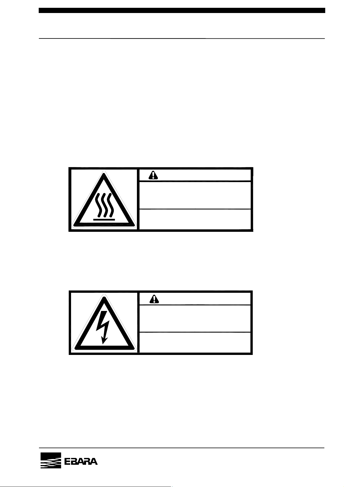
Following safety warning labels are attached to pump covers.
1. High temperature warning
2. Hazardous voltage warning
3. Hazardous materials warning
4. Electric charge mark
5. Hazardous weight danger
1. High temperature warning
Hot surface may burn or cause injury.
Allow the piping and casing to cool before servicing.
(vi)
WARNING
Hot Surfaces
Will burn skin on contact.
Allow piping and casing to cool
Before servicing
高温部あり。接触すると火傷をする危険があります。
配管・ケーシングが冷えてからメンテナンスをして下さい。
警 告
C-7110-312-0001
2. Hazardous voltage warning
Hazardous Voltage may shock, burn, or cause death.
Turn power off and lockout before servicing.
WARNING
Hazardous Voltage
Contact will cause injury or death by
electrical shock. Disconnect
line power before servicing.
危険電圧部あり。接触すると重傷または死亡の
危険があります。電源供給を止めてブレーカを切った状態で
メンテナンスをして下さい。
警 告
C-7110-313-0001
PM10U
EBARA
CORPORATION
Page 9
pprop
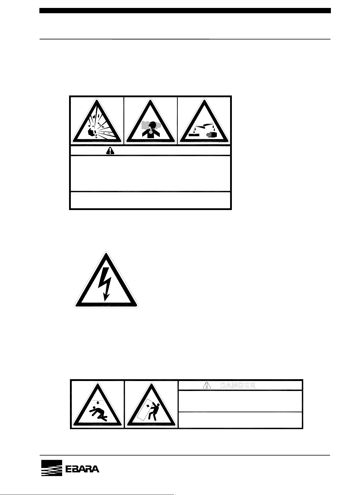
3. Hazardous materials warning
In case of hazardous materials are handled. Run the pump only with
N2 gas purge before servicing. Take adequate measures against
dangerous reaction and contact with human body.
(vii)
WARNING
Hazardous Materials
Exposure to air may cause spontaneous fire or explosion.
Inhalation or skin absorption will cause severe injury or
death by poisoning.
Purge thoroughly with nitrogen for at least 30 minutes
before servicing. Use personal protective equipment
a
riate to the materials to prevent exposure.
危険物質あり。
危険反応・人体への接触により重傷または死亡の危険があります。N2パージのみで30分以上
空運転を行なってから、危険物質のMSDSに従ってメンテナンスをして下さい。
4. Electric charge mark
警 告
C-7110-314-0001
PM10U
5. Hazardous weight danger
Heavy weight may cause severe injury or death due to overturning
or falling pump. Keep out from under the lifted pump.
Raise all adjuster-feet fully when moving.
危 険
Heavy Object
Can cause impact injury through falling or tipping.
Use appropriate, properly rigged lifting equipment and keep from
under suspended pump. Raise all adjuster feet fully when moving.
重量物。落下及び転倒により重傷または死亡の危険があります。
吊り上げたポンプの下に入らないで下さい。
移動時は全アジャスタフットを上限まであげて下さい。
C-7110-316-0001
EBARA
CORPORATION
Page 10
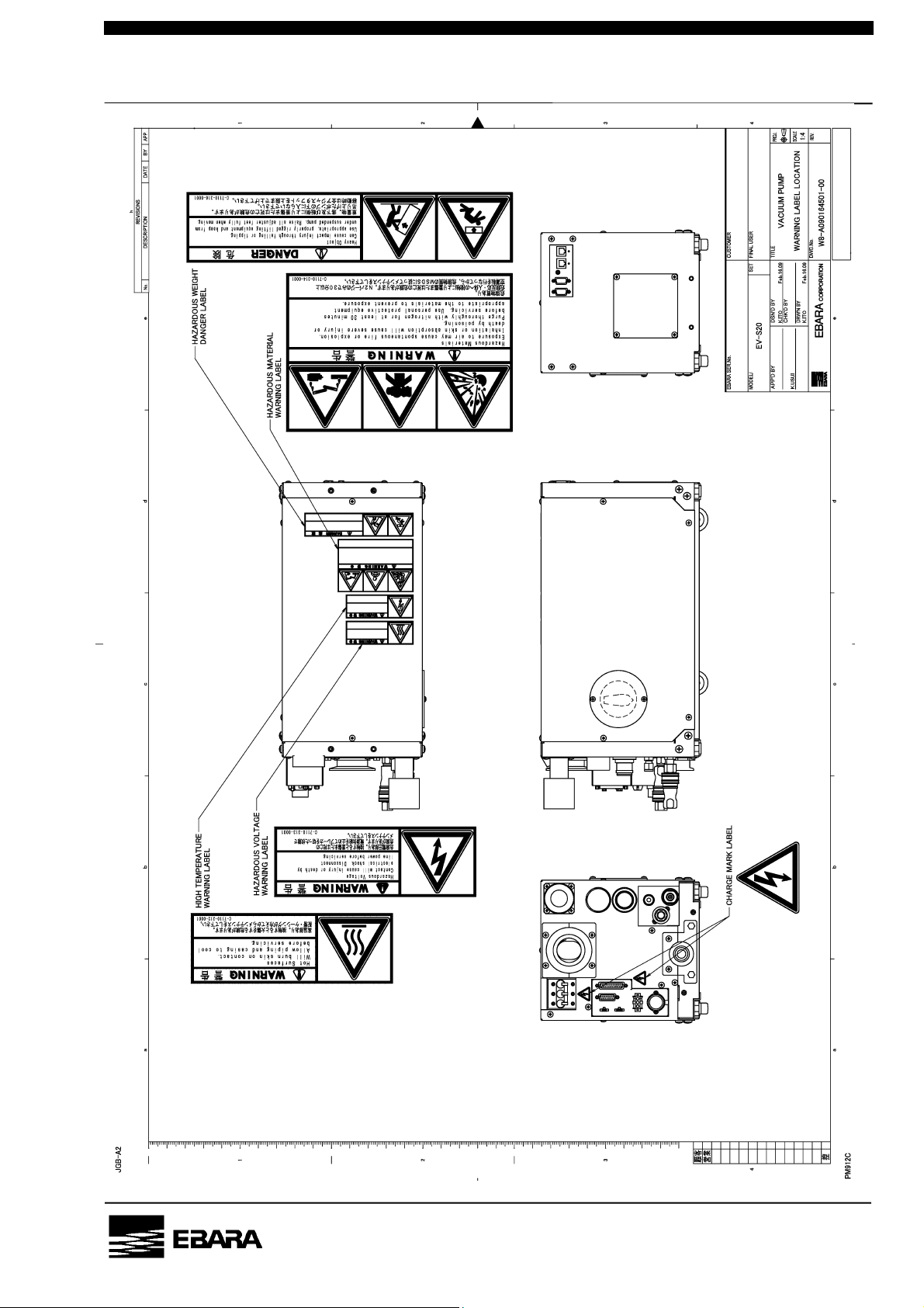
LOCATION, WARNING LABEL1
(viii)
PM10U
EBARA
CORPORATION
Page 11
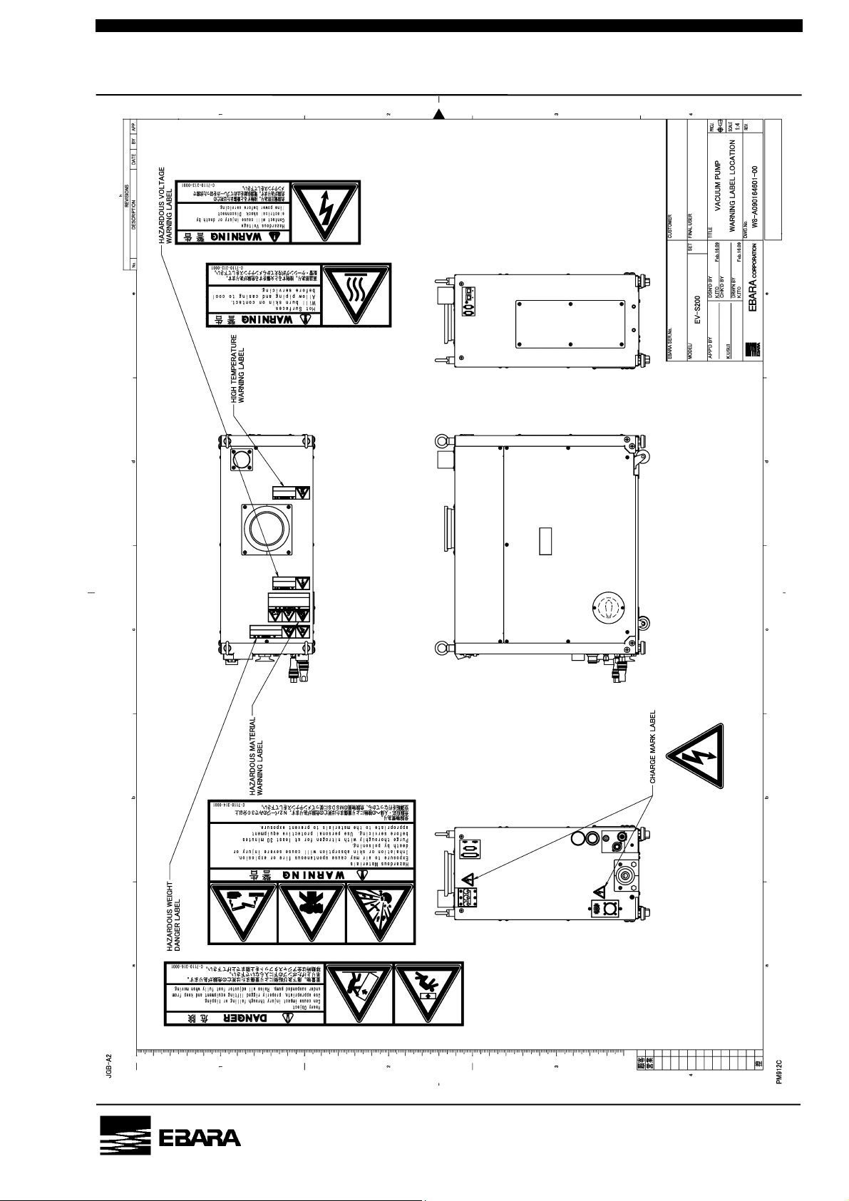
LOCATION, WARNING LABEL2
(ix)
PM10U
EBARA
CORPORATION
Page 12
Safety Interlocks
WARNING Check Safety Interlock functions periodically (every 6 months)
to confirm the interlocks will work correctly.
NITROGEN FLOW LOW
A normally open flow switch breaks when nitrogen supply to the pump (oil
bearing(s) and inter stage injection) drops below its factory set point, opening the
motor starter relay(s) and shutting down the pump. Restoration of sufficient
nitrogen flow permits restarting the pump.
OTOR OVERLOAD
M
(x)
Motor thermostat protect the pump motor from overheating due to extended current
draws in excess of the motor rating. Under a persistent overload condition, motor
thermostat opens a contact, which interrupts the motor run circuit. A brief cool
down interval permits restarting the pump.
PM10U
EBARA
CORPORATION
Page 13
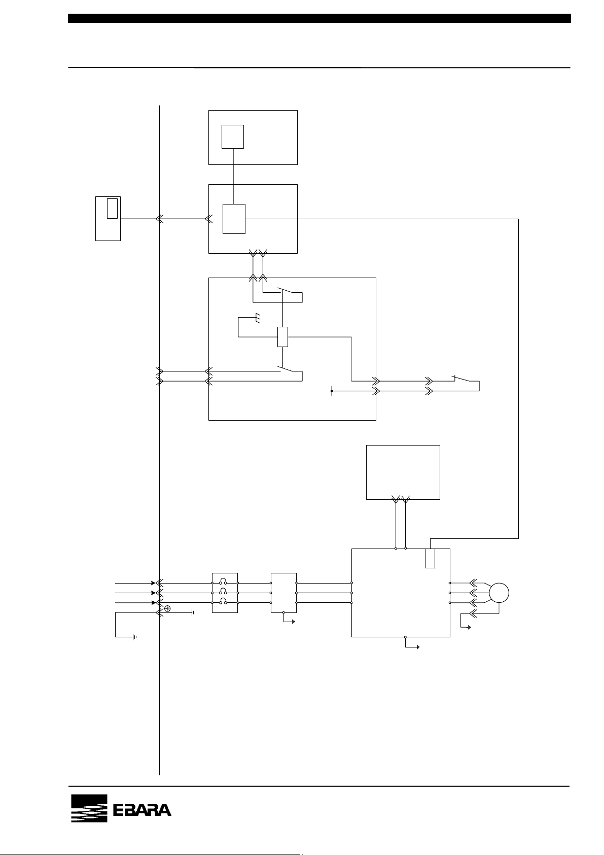
Interlock Schematic(EV-S20)
(xi)
CPU
RESET
CPU
LCD controller
(CN_1)
[ INTERLOCK BOARD ]
(EXT.IL)
(CN_11) 1 2
[ DVP402 ]
[ DVP401 ]
2
1
(CN_8)
2
1
X1
+12V
12
(CN_8)
13
(MP-TH)
MP
THRMO
MOTOR
RS485 communication
[ DVP414]
3
1
(CN_1)
User side
RST
POWER SUPPLY
3φ3W 200VAC 50Hz
3φ3W 200-220VAC 50/60Hz
E
(CN_A)
C
AB
Pump side
-
B1
[ UL1077 ]
CP
NOIZE
FILTER
E
E
RST
[ MP MOTOR DRIVER ]
CPU
M
UVW
E
E
PM10U
EBARA
CORPORATION
Page 14
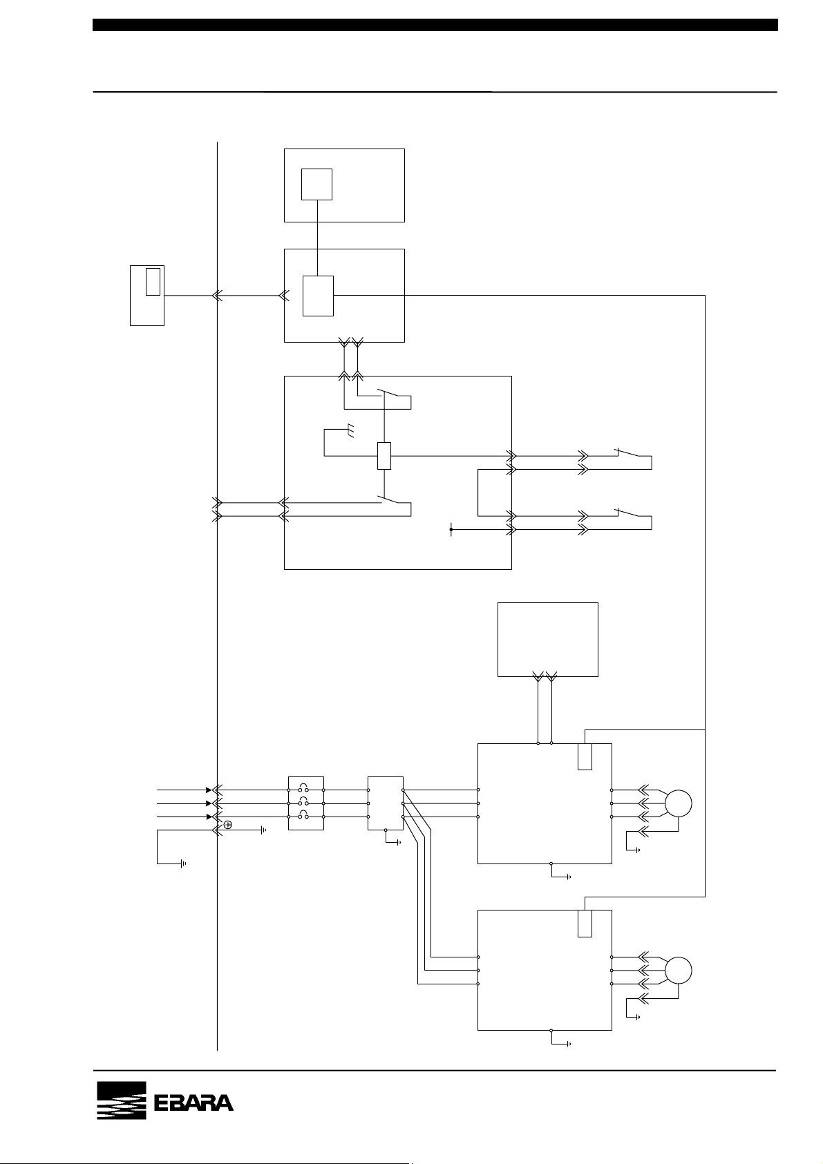
Interlock Schematic(EV-S50/ EV-S100/ EV-S200)
(xii)
CPU
RESET
CPU
LCD controller
(CN_1)
[ INTERLOCK BOARD ]
(EXT.IL)
(CN_11) 1 2
[ DVP402 ]
[ DVP401 ]
2
1
(CN_8)
2
1
X1
+12V
12 12
(CN_8) (CN_9)
13 13
(MP-TH) (BP-TH)
RS485 communication
BP
THRMO
MOTOR
MP
THRMO
MOTOR
[ DVP414]
3
1
(CN_1)
User side
RST
POWER SUPPLY
3φ3W 200VAC 50Hz
3φ3W 200-220VAC 50/60Hz
E
Pump side
-
B1
[ UL1077 ]
C
AB
(CN_A)
CP
NOIZE
FILTER
E
E
RST
[ MP M OTO R DRI VER ]
RST
[ BP MOTOR DRIVER ]
CPUCPU
M
UVW
E
E
M
UVW
E
E
PM10U
EBARA
CORPORATION
Page 15

(xiii)
Standard Limited Warranty
The terms of this Warranty limit the liability of EBARA CORPORATION. Please read it carefully.
Duration
For new pumps, the Warranty period shall be one (1) year from the date of commencing
operation by user or 18 months from shipment by EBARA, whichever comes first. This
Warranty does not apply to service beyond these time periods.
For overhauled pumps, the warranty period shall be six (6) months from shipment by EBARA.
Coverage
For the duration of the Warranty period, EBARA warrants this ESA pump from failure due to
defects in materials or workmanship. For such failures, EBARA will, at its option, either replace
or repair the pump free of charge
Such repair or replacement will not extend the duration of the warranty beyond the original
period.
For repairs not covered under this Warranty, EBARA will charge the customer for parts and
labor.
Exclusions and Limitations
This Warranty does not cover the following:
1. Failure due to operating the pump in a manner or under conditions other than as described
in the instruction manual.
2. Failure due to corrosion, byproducts or foreign material entering the pump.
3. Failure due to fire, flood, earthquake, Acts or God, Acts of War or other circumstances
beyond EBARA’s control.
Disassembly or repair of the pump by parties other than EBARA or EBARA-authorized
suppliers will void this Warranty.
EBARA’s liability is limited to repair or replacement of the pump under Warranty. EBARA
accepts no liability for consequential damages, including injury to personnel and damage to
facilities, tools or product.
EBARA makes no Warranty of merchanability, beyond statuatory requirements, or of fitness for
a specific purpose.
PM10U
EBARA
CORPORATION
Page 16
(xiv)
PM10U
EBARA
CORPORATION
Page 17

(xv)
Contents
Environmental Basic Policies..........................................................i
Safety Information..................................................................................ii
Important Prior Warnings.................................................................iii
Safety Interlocks .....................................................................................x
Standard Limited Warranty ...................................................................xiii
Contents........................................................................................................xv
1. Foreword...................................................................................................17
2. Introduction ............................................................................................17
2.1 Introduction........................................................................................17
2.2 Environmental Concerns.....................................................................3
3. Product Description...................................................................................4
3.1 Outline...................................................................................................4
3.1.1 Pump Module................................................................................4
3.1.2 N2 Gas (EV-S**P / EV-S**N)...........................................................4
3.1.3 Cooling Water ...............................................................................5
3.1.4 Exhaust..........................................................................................5
3.2 Control System ....................................................................................5
3.2.1 Warning .........................................................................................5
3.2.2 Operation Status Control.............................................................6
3.3 The way of pump moving....................................................................6
3.3.1 Preparation....................................................................................6
3.3.2 Moving method .............................................................................7
3.4 Release and shut off residual internal energy...................................8
3.4.1 Electrical Power - Lockout and Tagout.......................................8
3.4.2 Cooling water................................................................................9
3.4.3 Nitrogen (N2)..................................................................................9
3.4.4 Returning to Service.....................................................................9
PM10U
3.5 Detailed Specifications......................................................................10
3.5.1 Model Description .........................................................................10
EV-S20 OUTLINE DRAWING..................................................................15
EV-S20P / EV-S 20N OUTLINE DRAWING.............................................16
EV-S50 OUTLINE DRAWING..................................................................17
EV-S50P / EV-S50N OUTLINE DRAWING..............................................18
EV-S100 OUTLINE DRAWING................................................................19
EV-S100P / EV-S 100N OUTLINE DRAWING.........................................20
EV-S200 OUTLINE DRAWING................................................................21
EBARA
CORPORATION
Page 18

EV-S200P / EV-S 200N OUTLINE DRAWING.........................................22
Performance Curve ................................................................................23
4. Installation................................................................................................26
4.1 Movement and Fixation.....................................................................26
4.1.1 Location.......................................................................................26
4.1.2 Caster and adjustment foot .......................................................26
4.1.3 Pump Fixation (Option)..............................................................27
4.2 Piping..................................................................................................32
4.2.1 Vacuum and Exhaust Piping......................................................32
4.2.2 Cooling Water Piping..................................................................33
4.2.3 N2 Gas Piping..............................................................................34
4.3 Electrical Wiring.................................................................................35
4.3.1 Power Supply Wiring..................................................................36
(xvi)
4.3.2 Control Signal Wiring.................................................................37
4.3.3 Additional Emergency Off (EMO) input.....................................41
4.4. Power Supply for the Options (Connector CN-C).............................42
5. LCD Controller..........................................................................................43
5.1 LCD Outline........................................................................................43
5.2 LCD Indication....................................................................................44
5.3 Setting the operational mode............................................................48
5.3.1 Setting the pump operation control mode................................50
5.3.2 Setting the DIP switch................................................................50
5.3.3 Setting the pump running mode................................................51
5.3.4 Setting the rotational speed in the S. ENERGY mode.............51
5.3.5 Setting the rotational speed in the S. ENERGY mode................52
5.3.6 Setting the pump N2 flow low warning threshold ......................52
5.3.7 Setting the Water flow low warning threshold............................53
5.3.8 Setting the Back Pressure high warning threshold ...................53
5.4 Dip Switch...........................................................................................54
5.5 DIP Switch setting display ................................................................57
PM10U
6. Operation ..................................................................................................59
6.1 Before Starting...................................................................................59
6.2 START/STOP......................................................................................62
6.2.1 LOCAL (Pump Side) Start/Stop .................................................63
6.2.2 REMOTE Start/Stop ....................................................................63
6.2.3 COMMUNICATION Start/Stop ....................................................64
6.3 Operation when momentarily power failure happens .....................64
EBARA
CORPORATION
Page 19

7. Maintenance and Inspection ...................................................................64
7.1 Internal energies ................................................................................64
7.1.1 Power source ..............................................................................64
7.1.2 Cooling water .............................................................................. 64
7.1.3 Nitrogen gas................................................................................64
7.2 Routine Inspection............................................................................. 65
7.3 Vacuum and Exhaust Piping............................................................. 66
7.4 Lubricating Oil.................................................................................... 68
7.5 Spare (Maintenance) Parts List.........................................................70
7.6 List of wastes during maintenance .................................................. 71
7.7 Overhaul ............................................................................................. 71
8. Disconnection and Transportation.........................................................72
9. For SEMI S2 standard................................................................................. 74
(xvii)
10. Troubleshooting .......................................................................................75
10.1 Troubleshooting (1) Basic trouble .................................................... 76
10.2 Troubleshooting (2) WARNING.......................................................77
10.3 Troubleshooting (3) ALARM ...........................................................78
10.4 Troubleshooting (4) Option.............................................................79
PM10U
EBARA
CORPORATION
Page 20
P.1
1. Foreword
We appreciate that you have selected an EBARA Model EV-S series dry vacuum
pumps. These pumps have been manufactured with much care and attention so
that it can be operated safely and satisfactorily.
Incorrect operation will result in lack of performance and cause accidents and
injuries to personnel.
[ NOTE ] This instruction manual contains all necessary information on
operation and maintenance of the pump.
Be sure to operate the pump correctly in accordance with these
instructions to ensure a long service life.
Keep this instruction manual in a suitable place for immediate
reference whenever needed.
2. Introduction
2.1 Introduction
Check the following items on receipt of the pump package.
(1) Check that the nameplate affixed to the outer cover of the pump to confirm
that the pump supplied agrees with your order.
Check the accessories against the packing list and the previously submitted
drawings and documents to confirm that the all ordered accessories have
been supplied.
(2) Check whether damage has occurred or screws/bolts have worked
themselves loose in transit.
CAUTION Notify EBARA without delay when damage is discovered or
when components are missing. Do not use when a leak is
present as this will result in accident.
PM10U
(3) Store the pump in a dry and clean place if it is not installed at once after
delivery.
Temperature : 5-40°C
Humidity : 80% or less
(4) Pump must be placed in an upright position.
EBARA
CORPORATION
Page 21
P.3
2.2 Environmental Concerns
Handling or operating the unit other than specified may induce adverse impacts on the
environment. Follow the descriptions below to handle, operate, and maintain the unit.
(1) Ask an authorized waste-disposal company to dispose packing materials from
uncrating according to laws and ordinances applicable to the waste.
(2) Failure to do the unit maintenance (including overhaul) may trigger accidents causing
injury or death, unit troubles, or environmental pollution. Plan the maintenance and
perform it periodically to operate the unit efficiently.
(3) To dispose the unit, follow effective laws and ordinances applicable in the area where
the unit is installed.
(4) To dispose the lubricant oil and chemicals, follow effective laws and ordinances
applicable in the area where the unit is installed.
WARNING If the pump becomes damaged during shipment or if parts are missing,
immediately contact EBARA. If a leaking or damaged product is used,
an accident resulting in injury or death could occur or the product
could become further damaged. Even if leakage occurs, take
measures to ensure they will not be directly discharged from the site,
as such leakage also wastes resources.
CAUTION If the product is not to be immediately installed, store it in a clean, dry
location.
PM10U
EBARA
CORPORATION
Page 22

P.4
3. Product Description
3.1 Outline
These pumps have a compact design and includes various sensors and controls
to enhance reliability and operation.
3.1.1 Pump Module
The pump is Roots type vacuum pump which rotates a pair of non-contact
multi-stage rotors synchronized by timing gears.
The timing gears and bearings are enclosed in a compartment which is
independent of the casing. For lubrication Perfluoro-Polyether (PFPE) oil and
grease are used.
The pumps of this series are factory filled with lubrication oil. Use only the
recommended lubrication oil grades shown in specification Table 3.1 for
replenishing or replacing.
3.1.2 N2 Gas (EV-S**P / EV-S**N)
Introduce nitrogen gas to dilute the hazardous gases to an unharmful level.
Properly connect the nitrogen gas line to the purge port provided according to the
instructions in Table 3.1 and the descriptions in Section 4.2.3. In the cases the
gas concentration may become higher than the specified for safe gas exhaust,
introduce the nitrogen gas to lines to the exhaust outlet. The tool user shall
provide the purge port for this purpose.
gas is also required to supply to seal the shaft section. This protects the
N
2
penetration to bearing section, such as corrosive gas. To reduce pump corrosion
due to process gas or accumulation of reaction by-products, N2 gas is supplied to
each pump component as dilution purge gas. Stopping the dilution N2 with a
selector valve can save N2 gas, when process does not produce corrosion and
reaction by-products. The correct amount of N2 gas is supplied for those two
PM10U
types of purge operation, by adjusting the regulation pressure to the specified value.
The nitrogen gas selector is locating on the right side of the unit, facing the utility
connectors. It is under the outer cover.
EBARA
CORPORATION
Page 23

P.5
3.1.3 Cooling Water
Because the pump compresses gas from a vacuum to atmospheric pressure,
compression heat is generated. Therefore cool the pump with cooling water.
The cooling water connector takes the form of a coupler for easy connection and
disconnection.
3.1.4 Exhaust
A check valve is built into the pump unit to prevent reverse flow of gas from the
exhaust through the pump to the vacuum chamber when pump is stopped.
3.2 Control System
These pumps have a built-in unit consisting of a Circuit Protector (CP), Noise
Filter (NF), control source.
To improve reliability and safety, the condition of each utility and pump section is
monitored by a sensor.
During pump operation all operating conditions are monitored, including power
supply, cooling water flow, N2 gas flow, casing and motor coil temperature, motor
speed, and electric power for motor.
Continuous operation is possible when there is a momentarily power failure (170V
or less) of 1 sec or less.
3.2.1 Warning
To assure the reliability of the pump as a vacuum exhaust system, the pump
protection system generates two levels of alarm: WARNING and ALARM.
A WARNING signal is generated when pump operation exceeds the normal range.
It therefore only draws attention that the normal operating values are not adhered
to but does not signify that danger is imminent. The pump will continue to operate
in this condition.
An ALARM signal output is generated and the pump will stop automatically when
PM10U
the upper mechanical safety limit is reached during pump operation.
EBARA
CORPORATION
Page 24
P.6
When an ALARM output is suddenly generated, while the plant unit is operational,
a WARNING signal will be generated to ensure that the plant operation is not
discontinued. This enables the operator to check the pump after the equivalent of
one cycle has been completed.
Be sure to contact EBARA Corporation for details on checking the WARNING and
ALARM setting conditions.
3.2.2 Operation Status Control
The sensor data are displayed on the LCD provided on the controller to facilitate
operation status control and daily inspection.
All WARNING and ALARM signals are displayed on the LCD. For remote
operation and monitoring, the signals are available as individual and group
outputs.
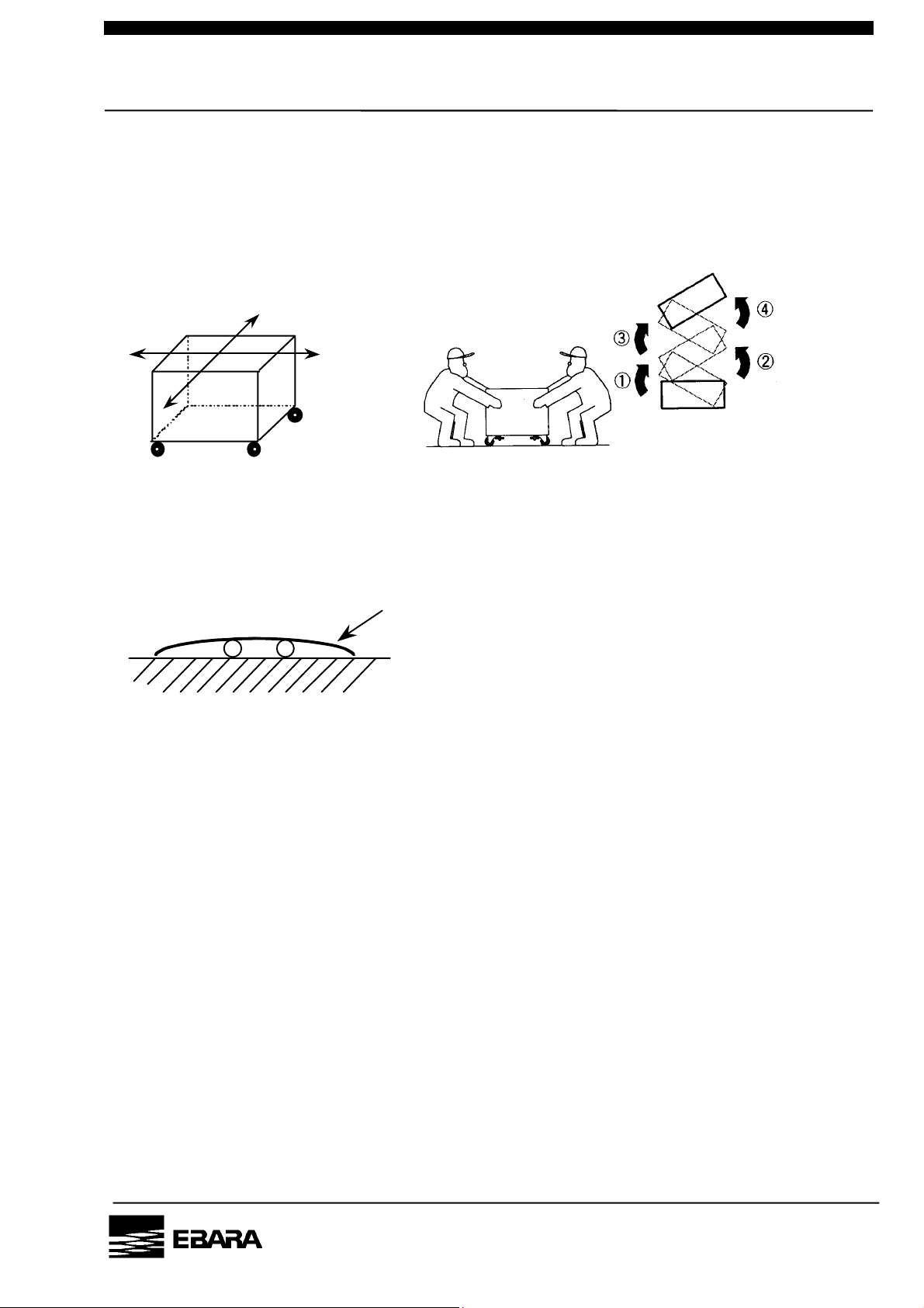
3.3 The way of pump moving
3.3.1 Preparation
Before pump moving, all adjuster feet shall be raised fully at four places.
In case of being not raised fully, pump may be tripped over by obstacle on floor.
PM10U
EBARA
CORPORATION
Page 25
P.7
3.3.2 Moving method
Move pump slowly by pushing eye bolt toward direction A. Be sure not to be
caught by toes. If pump needs to be moved toward direction B in order to be set at
a corner or narrow spaces, two persons shall move the pump by pushing its
terminal portion alternately as directed below.
B
A
If pump needs to be moved on steps or ditches, spread steel plate or the like which
can sustain the pump weight over the steps / ditches and pump shall be moved on
it by two persons with care.
Steel Plate
If pump should lose its balance when moving and start tripping over, never try to
sustain the pump, get away from the pump immediately.
PM10U
EBARA
CORPORATION
Page 26
P.8
3.4 Release and shut off residual internal energy
WARNING To avoid dangers potentially encountered during maintenance,
transportation or storage, follow instructions below to shut off
power.
WARNING Capacitors within the control panel retain residual energy after
interruption of power supply. Wait five (5) minutes after shutting
off breaker before opening the control panel. Carefully check that
bleed circuits have discharged the residual energy before servicing
the control panel.
WARNING To comply with SEMI S2, install lockable shutoff devices on electrical,
nitrogen and cooling water supplies. These devices should be
adjacent to and within sight of the pump.
3.4.1 Electrical Power - Lockout and Tagout
Lock the branch circuit in the OFF position and tag it out to perform maintenance or
troubleshooting.
1. Verify that the LCD display is lit (confirming that pump is powered).
2. Turn the branch circuit disconnect off.
3. Insert padlock through holes provided on locking device. Close padlock and
attach tag.
4. Keep the key with you while working. Prepare the tagout label per factory
procedures.
5. Verify that LCD display is unlit (confirming that pump is unpowered).
6. If unable to confirm interruption of power via LCD display, use a voltmeter to
probe contacts at Connector CN-C. Potential between any two pins indicates
PM10U
that electrical power to the pump is not interrupted.
7. The Lockout/Tagout procedures must comply with OSHA 29 CFR 1910.147
and 1910.331-335
EBARA
CORPORATION
Page 27

P.9
3.4.2 Cooling water
1. Close [facility] water supply to stop water supply to the pump, then close water
return valve. Follow [facility] procedures for locking these valves in the off
position.
2. Push the knurled outer ring of the quick-connect couplers toward the pump to
disconnect the water hoses. Carefully remove the male coupling halves
from the hoses and remake the quick-connects to drain the pump lines. Have
a catchment vessel and absorbent cloths at hand before removing the
couplings.
3. Make sure water outflow stops from both the facility lines and the pump.
3.4.3 Nitrogen (N2)
1. Close [facility] nitrogen supply valve and follow facility procedures for locking
this valve in the off position.
2. Verify that the nitrogen pressure gauge (on front panel of the pump) drops to 0
MPa, confirming that no pressurized gas energy is stored in the pump.
3. Pull out the red detent ring on the N2 regulator.
4. Turn knob counterclockwise until pressure gauge reads 0 MPa. (Both N2
regulator knob and nitrogen pressure gauge are located on front panel of the
pump.)
5. Disconnect tube connection of N2 supply line by turning tube nut
counterclockwise.
6. Plug (cap) ¼” tube connector on the pump with a tube fitting cap.
3.4.4 Returning to Service
1. Unlock and open water and nitrogen valves.
2. Remove handle stop bracket and switch circuit breaker on.
3. Restrart pump and open foreline valve only after appropriate leak checks and
safety verifications.
PM10U
EBARA
CORPORATION
Page 28
P.10
3.5 Detailed Specifications
The following tables and figures should be consulted for pump specification,
dimension and performance details.
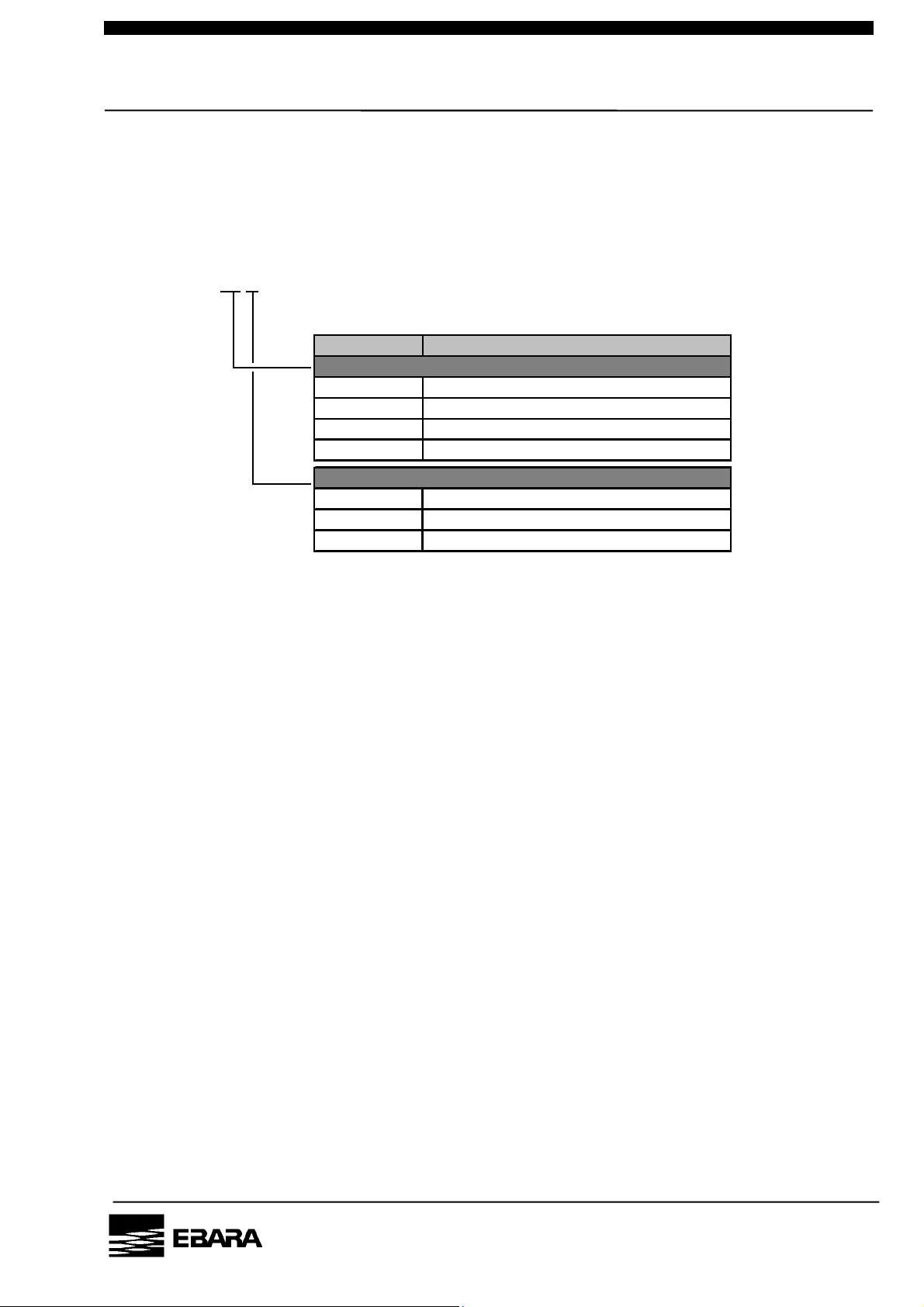
3.5.1 Model Description EV – S 20 P
Mark Description
Pumping Speed
20 1670 L/min
50 5000 L/min
100 10000 L/min
200 20000 L/min
Materials / N2 Purge Unit
- Standard / Without N2 purge unit
P Standard / With N2 purge unit
N Corrosion Resistant / With N2 purge unit
PM10U
EBARA
CORPORATION
Page 29
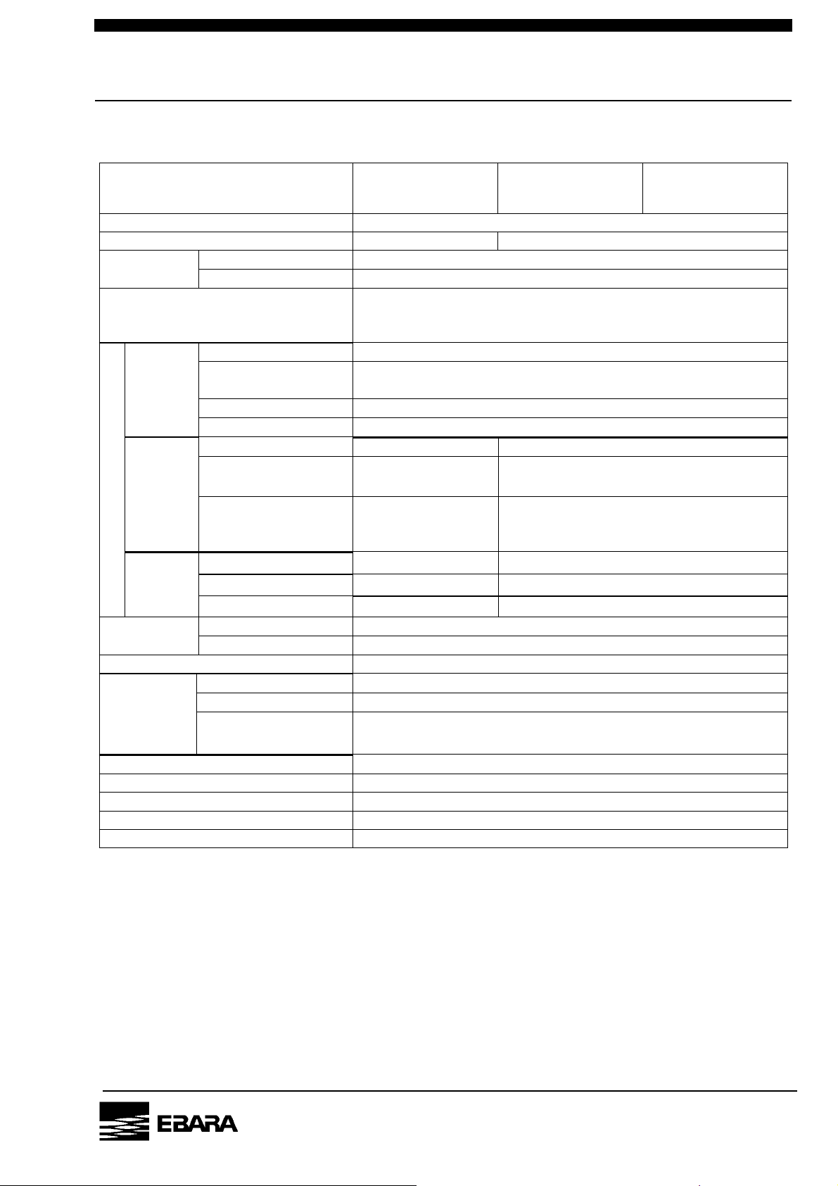
P.10
Table 3.1 Specifications (EV-S20 / EV-S20P / EV-S20N)
Model
Pumping Speed 1670 L/min
Ultimate Pressure 3.0 Pa 5.0 Pa
Connection
Gas Outlet NW25
Approx. Power at Ultimate
Pressure
(Max. Power)
Connection Rc1/4 (Coupler)
Cooling
Water
[Gauge Press.]
Temperature Max. 30°C
Connection ---------- 1/4” Tube Fitting (Same as SWAGELOK)
Util
i-ty
N2
[Gauge Press.]
Gas
Approx. Flow Rate
[N2-0 Mode]
Duct
Connection ---------- Φ50 mm
Venti-
Lation
Approx. Flow Rate ---------- 0.5 m
Lubrication
Oil
Approx. Weight 60 kg
Phase/Volt/Freq. 3 Phase, 200-220V , 50 / 60Hz
Power
Supply
Power Capacity 3.2 kVA
Connection
Control Signal D-sub 15 Pin + D-sub 25 Pin
Communication RS-232C D-sub 9 Pin X 2
CP Rating 15 A
SCCR 1.0 kA
Airborne noise test data 57 dB
Model
EV-S20
Model
EV-S20P
Model
EV-S20N
Gas Inlet NW50
0.4 kW
(2.2 kW)
Pressure
Differential Press.: Min. 0.2 MPa
Supply: Max. 0.4 MPa
Flow Rate 1.5 - 3.0 L/min
Pressure
----------
----------
Supply: 0.15 - 0.7 MPa
[Setting: 0.09 - 0.012 MPa]
3
17 - 20 Pa m
[2.4 Pa m
3
/s
/s]
Pressure ---------- -196 Pa
3
/min
Brand BARRIERTA J100ES (NOK)
Quantity 0.05 L
Amphenol
C016 20C003 100 12
PM10U
[Note] The ambient temperature of the pump installation place shall be 30 degrees of
centigrade of lower.
EBARA
CORPORATION
Page 30
P.11
Table 3.2 Specifications (Model EV-S50 / EV-S50P / EV-S50N)
Model
Pumping Speed 5000 L/min
Ultimate Pressure 0.5 Pa
Connection
Gas Inlet NW50
Gas Outlet NW25
Approx. Power at Ultimate Pressure
(Max. Power)
Connection Rc1/4 (Coupler)
Cooling
Water
Pressure
[Gauge Press.]
Flow Rate 2.0 - 3.0 L/min
Temperature Max. 30°C
Connection ---------- 1/4” Tube Fitting (Same as SWAGELOK)
Utili-
ty
N2
Pressure
[Gauge Press.]
Gas
Approx. Flow Rate
[N2-0 Mode]
Duct
VentiLation
Lubrication
Oil
Connection ---------- Φ50 mm
Pressure ---------- -196 Pa
Approx. Flow Rate ---------- 0.5 m
Brand BARRIERTA J100ES (NOK)
Quantity 0.1 L
Approx. Weight 100 kg
Phase/Volt/Freq. 3 Phase, 200-220V , 50 / 60Hz
Power
Supply
Power Capacity 4.8 kVA
Connection
Control Signal D-sub 15 Pin + D-sub 25 Pin
Communication RS-232C D-sub 9 Pin X 2
CP Rating 20 A
SCCR 1.0 kA
Airborne noise test data 57 dB
Model
EV-S50
Model
EV-S50P
Model
EV-S50N
0.55 kW
(3.6 kW)
Differential Press.: Min. 0.2 MPa
Supply: Max. 0.4 MPa
----------
----------
Japan Aviation Electronics Industry
JL04HV-2E22-22PE-B
Supply: 0.15 - 0.7 MPa
[Setting: 0.09 - 0.012 MPa]
3
3
/min
3
/s
/s]
17 - 20 Pa m
[2.4 Pa m
PM10U
[Note] The ambient temperature of the pump installation place shall be 30 degrees of
centigrade of lower.
EBARA
CORPORATION
Page 31

P.12
Table 3.3 Specifications (EV-S100 / EV-S100P / EV-S100N)
Model
Pumping Speed 10000 L/min
Ultimate Pressure 0.5 Pa
Connection
Gas Inlet NW80
Gas Outlet NW40
Approx. Power at Ultimate Pressure
(Max. Power)
Connection Rc1/4 (Coupler)
Cooling
Water
Pressure
[Gauge Press.]
Flow Rate 2.0 - 3.0 L/min
Temperature Max. 30°C
Connection ---------- 1/4” Tube Fitting (Same as SWAGELOK)
Utili-
ty
N2
Pressure
[Gauge Press.]
Gas
Approx. Flow Rate
[N2-0 Mode]
Duct
Venti-
Lation
Lubrication
Oil
Connection ---------- Φ50 mm
Pressure ---------- -196 Pa
Approx. Flow Rate ---------- 0.5 m
Brand BARRIERTA J100ES (NOK)
Quantity 0.1 L
Approx. Weight 120 kg
Phase/Volt/Freq. 3 Phase, 200-220V , 50 / 60Hz
Power
Supply
Power Capacity 6.4 kVA
Connection
Control Signal D-sub 15 Pin + D-sub 25 Pin
Communication RS-232C D-sub 9 Pin X 2
CP Rating 30 A
SCCR 1.0 kA
Airborne noise test data 57 dB
Model
EV-S100
Model
EV-S100P
Model
EV-S100N
0.65 kW
(4.6 kW)
Differential Press.: Min. 0.2 MPa
Supply: Max. 0.4 MPa
----------
----------
Japan Aviation Electronics Industry
JL04HV-2E22-22PE-B
Supply: 0.15 - 0.7 MPa
[Setting: 0.09 - 0.012 MPa]
3
3
/min
3
/s
/s]
17 - 20 Pa m
[2.4 Pa m
PM10U
[Note] The ambient temperature of the pump installation place shall be 30 degrees of
centigrade of lower.
EBARA
CORPORATION
Page 32

P.13
Table 3.4 Specifications (EV-S200 / EV-S200P / EV-S200N)
Model
Pumping Speed 20000 L/min
Ultimate Pressure 0.5 Pa
Connection
Gas Inlet NW100
Gas Outlet NW40
Approx. Power at Ultimate Pressure
(Max. Power)
Connection Rc1/4 (Coupler)
Cooling
Water
Pressure
[Gauge Press.]
Flow Rate 2.0 - 3.0 L/min
Temperature Max. 30°C
Connection ---------- 1/4” Tube Fitting (Same as SWAGELOK)
Utili-
ty
N2
Pressure
[Gauge Press.]
Gas
Approx. Flow Rate
[N2-0 Mode]
Duct
Venti-
Lation
Lubrication
Oil
Connection ---------- Φ50 mm
Pressure ---------- -196 Pa
Approx. Flow Rate ---------- 0.5 m
Brand BARRIERTA J100ES (NOK)
Quantity 0.15 L
Approx. Weight 170 kg
Phase/Volt/Freq. 3 Phase, 200-220V , 50 / 60Hz
Power
Supply
Power Capacity 6.8 kVA
Connection
Control Signal D-sub 15 Pin + D-sub 25 Pin
Communication RS-232C D-sub 9 Pin X 2
CP Rating 30 A
SCCR 1.0 kA
Airborne noise test data 63 dB
Model
EV-S200
Model
EV-S200P
Model
EV-S200N
0.75 kW
(5.1 kW)
Differential Press.: Min. 0.2 MPa
Supply: Max. 0.4 MPa
----------
----------
Japan Aviation Electronics Industry
JL04HV-2E22-22PE-B
Supply: 0.15 - 0.7 MPa
[Setting: 0.09 - 0.012 MPa]
3
3
/min
3
/s
/s]
17 - 20 Pa m
[2.4 Pa m
PM10U
[Note] The ambient temperature of the pump installation place shall be 30 degrees of
centigrade of lower.
EBARA
CORPORATION
Page 33

P.14
EV-S20 OUTLINE DRAWING
PM10U
EBARA
CORPORATION
Page 34

P.15
EV-S20P / EV-S 20N OUTLINE DRAWING
PM10U
EBARA
CORPORATION
Page 35

P.16
EV-S50 OUTLINE DRAWING
PM10U
EBARA
CORPORATION
Page 36

P.17
EV-S50P / EV-S50N OUTLINE DRAWING
PM10U
EBARA
CORPORATION
Page 37

P.18
EV-S100 OUTLINE DRAWING
PM10U
EBARA
CORPORATION
Page 38

P.19
EV-S100P / EV-S 100N OUTLINE DRAWING
PM10U
EBARA
CORPORATION
Page 39

P.20
EV-S200 OUTLINE DRAWING
PM10U
EBARA
CORPORATION
Page 40

P.21
EV-S200P / EV-S 200N OUTLINE DRAWING
PM10U
EBARA
CORPORATION
Page 41

P.22
Performance Curve
10000
EV-S20/EV-S20P
1000
EV-S20N
100
EV-S20
EV-S20P/EV-S20N
10
Pumping Speed (L/min)
1
0.1
1 10 100 1000 10000 100000
Inlet Pressure (Pa)
Fig 3.1 EV-S20(P/N) Performance Curve
10000
1000
EV-S50N
100
10
Pumping Speed (L/min)
EV-S50
EV-S50P
PM10U
1
0.1
0.1 1 10 100 1000 10000 100000
Inlet Pressure (Pa)
Fig 3.2 EV-S50(P/N) Performance Curve
EBARA
CORPORATION
Page 42

P.23
100000
10000
1000
100
Pumping Speed (L/min)
10
1
0.1
0.1 1 10 100 1000 10000 100000
Inlet Pressure (Pa)
EV-S100N
Fig 3.3 EV-S100(P/N) Performance Curve
100000
EV-S100
EV-S100P
10000
1000
100
Pumping Speed (L/min)
10
1
0.1
0.1 1 10 100 1000 10000 100000
Inlet Pressure (Pa)
EV-S200
EV-S200P
EV-S200N
Fig 3.4 EV-S200(P/N) Performance Curve
PM10U
EBARA
CORPORATION
Page 43

g
p
p
P.24
Power
N2 Gas
Water
Control
Connector
Circuit
Protector
Regulator
Pressure Gau
P
Pump N
FT1
LCD Controller
Control Circuit
Motor Driver 1
Motor Driver 2
e
Gas Flow Sensor
2
N
Selector Valve
2
FT2
Gas Inlet
Booster Pum
(BP)
Main Pum
(MP)
Motor 2
Motor 1
Gas Outlet
Silencer
Check Valve
* The EV-S20 pump is supplied without a booster pump (BP).
Figure 3.5 System Flow
EBARA
PM10U
CORPORATION
Page 44

P.25
4. Installation
Be sure to take the following cautions and instructions into account when
installing the pump.
4.1 Movement and Fixation
4.1.1 Location
These pumps are designed for indoor installation. To install the pump, select a
place with little exposure to dust and humidity and not subject to dew
condensation. Also allow for sufficient space to ensure easy pump installation
and disassembly for maintenance.
In case of installing interface box to the pump, the distance between pump
and interface box shall be 3m or less.
CAUTION Install pump in a location at an ambient not exceeding 30°C.
Particular caution is required when the pump is operated in
an enclosed room.
CAUTION A gap of at least 50mm should be left open for ventilation
between the pump cover and the adjacent equipment.
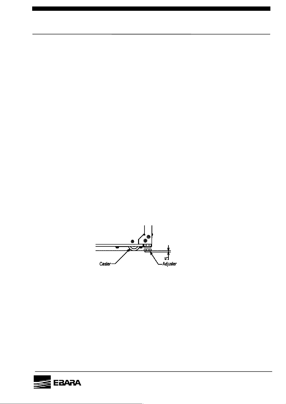
4.1.2 Caster and adjustment foot
Casters and adjusters of four each are attached under the pump base. When
moving the pump, lift up all of the four adjusters. To lift them up, use the
wrench and turn them to the left.
PM10U
Fig. 4.1 Caster
EBARA
CORPORATION
Page 45

P.26
WARNING Be careful not to overturn the pump when pushing and
pulling it sideways, because the width of the pump is small
to its height.
CAUTION The neck portion of the casters will vibrate during caster
movement. Be sure to keep your fingers and feet out.
CAUTION Do not step on the pump or place objects on it.
(3) To fix the pump, turn the adjusters to the right to lower them.
(4) Adjust the height of the feet evenly to ensure that the pump base is level.
The difference in height between the two sides of the pump base shall not
exceed 1mm.
The adjustment allowance is approximately 5 mm.
[ NOTE ] If the pump is not leveled, shortage of the lubrication oil supply to the
bearing may be caused.
[ NOTE ] To prevent vibrations and airborne noises, keep horizontal level of
pump with the adjustment feet.
4.1.3 Pump Fixation (Option)
The pumps are provided with casters for easy transportation and foot
adjustments for anchoring and height adjusting, as described in Section 3.1.2.
The pump, however, may unexpectedly move or fall down when an earthquake
occurs. To prevent such events, EV-S dry pumps (CE/SEMI compliant) are
equipped with brackets to secure the pump body to the floor. Fix the pump to
PM10U
the floor or other firm ground with the brackets at the installation.
For dimensions of the bracket, see the accompanying drawing.
Anchor bolts should be fit for conditions of the floor where the pump is
anchored.
EBARA
CORPORATION
Page 46

P.27
EV-S20 LOCATION,FIXTURE
PM10U
EBARA
CORPORATION
Page 47

P.28
EV-S50 LOCATION,FIXTURE
PM10U
EBARA
CORPORATION
Page 48

P.29
EV-S100 LOCATION,FIXTURE
PM10U
EBARA
CORPORATION
Page 49

P.30
EV-S200 LOCATION,FIXTURE
PM10U
EBARA
CORPORATION
Page 50

P.31
4.2 Piping
4.2.1 Vacuum and Exhaust Piping
Connect the vacuum and exhaust pipes to the suction and exhaust flanges.
A narrow clearance is maintained in the pump for rotor rotation. The ingress of
foreign objects into the pump interior will therefore prevent the pump from
operating. Be sure therefore to heed the following cautions when making the pipe
connections.
a) Remove all foreign matter from inside the piping.
b) When connecting be sure that no dirt or dust particles adhere to the flange
surfaces and/or that the flange surfaces are damaged.
Provide a suitable means of preventing the ingress of reaction by-products
adhering to the APC valve and wafer fragments. For this purpose, a filter may
be installed.
c) The weight of the pipes attached to the pump can cause misalignment and
leaks from the flange connections. Be sure therefore to support the piping
properly and not to apply undue force when aligning the flange faces.
It is recommended to insert flexible bellows when connecting the pipes to the
suction and exhaust flanges of the pump.
The length of the flexible bellows on the vacuum (suction) side will vary
according to the vacuum drawn. Be sure to connect so that no undue force can
be applied to the flexible bellows.
d) Please decide a part to connect to the pump exhaust so that the exhaust
pressuret is not beyond atmospheric pressure.
WARNING Be sure to check for leaks after you have installed the pump.
PM10U
Leaks will cause serious danger due to the discharge of harmful
and hazardous substances and the occurrence of unpredictable
reactions associated with the admission of air into the pump.
When checking for gas leaks by pressurization, please
pressurize by less than 0.05 MPa into the purge port and do
check.
EBARA
CORPORATION
Page 51

P.32
WARNING The pump casing, inlet piping and exhaust piping become
extremely hot during operation and for some time after
stopping. Be sure that pump and exhaust piping do not
come in contact with humans or inflammable substances.
Do not remove the pump cover during operation.
CAUTION The exhaust piping made by polyvinyl chloride causes the noise
thrugh the pipe.
4.2.2 Cooling Water Piping
Be sure to connect the cooling water pipes to the correct inlet and outlet ports.
The connector ports are provided with couplers. Push in the plug till the end of
socket. Socket sleeve returns to front.
Be sure that the supply/return plugs are not connected in reverse. The diameters
are slightly different. In/Out markings are provided on each plugs.
When the coupler is pulled out the water pipe will be automatically blocked. Use
cooling water corresponding to the specifications of Table 4.1 below.
Table 4.1 Industrial Water Supply Quality Specification
(Japan Industrial Water Association, Industrial
Water Quality Standards Committee)
Turbidity
pH
Alkalinity(CaCO3)
Hardness(CaCO3)
Evaporation residue
Chlorine ion
Iron
Manganese
(ppm)
(ppm)
(ppm)
(ppm)
(ppm)
(ppm)
(ppm)
20
6.5-8.0
75
120
250
80
0.3
0.2
PM10U
EBARA
CORPORATION
Page 52

P.33
CAUTION Even when the cooling water flow rate drops, the pump will
continue to operate until the pump part reach a temperature
corresponding to the safety limit.
The material selected for the water piping of facility side should
have a heat resistance so that it can withstand a maximum
temperature of at least 70℃ at the operating pressure.
CAUTION When several pumps are used, be sure to connect the cooling
water pipes to each pump in parallel. The cooling water will flow
more or less easily according to the type of pump and the
piping. Be sure to select the correct piping so as to ensure the
appropriate cooling water flow rate for all pipes used.
CAUTION When the cooling water connections are incorrect and the flow
is reversed, a flow rate different from the normal value will be
displayed. Nor will the pump will not be cooled properly.
This will result in accident.
Be sure therefore to connect correctly to avoid problems.
CAUTION When the cooling water supply is left on while the pump is
stationary dew condensation will form on the water-cooled
parts in locations with high humidity.
Make it a rule therefore to stop the cooling water when water
droplets can be detected on the outer surface of the pump
cooling water piping as this suggests the possibility of dew
condensation in the pump.
4.2.3 N2 Gas Piping
Cut tube at right angles and make the end-face perfectly smooth. Then connect
the tube to the tube fitting assembly of the N2 gas purge port. The tube is a
PM10U
push-fit onto the shoulder of the tube fitting assembly.
Secure the tube fitting assembly properly and tighten the retaining nut by hand.
After this, use a tool to tighten the nut further by 1 + 1/4 turns.
To connect the tube again after this, install the tube already fitted to the ferrule
and re-tighten the retaining nut slightly after the initial tightening (generally,
tighten by a further quarter turn after tightening by hand).
EBARA
CORPORATION
Page 53

P.34
Body
Front
Ferrule
Back
Ferrule
Nut
1 + 1/4
Rotation
Fig. 4.2 Tube Fitting Assembly
CAUTION For safety, be sure to use N2 gas which purity is more than 99.999%.
Impurities of N2 gas may cause an accident when the pump is used for
exhausting toxic and/or inflamable gases.
4.3 Electrical Wiring
WARNING Be sure to keep the power supply to the pump turned off and
lock-outed until you have finished the wiring and connecting
work. Also interrupt the Circuit Protector (CP) during this.
WARNING Electrical wiring shall be carried out only by qualified electricians.
CAUTION Do not apply the power supply from the pump's power pack to
any other equipment as this will result in malfunctioning of the
control units and in pump failure.
CAUTION ELB(or CB) is not installed in the pump unit. Please install
ELB(or CB) based on the law and the standard in the installation
region. (Please attach the Circuit breaker(CB) type of UL489 to
SEMI correspondence.)
PM10U
EBARA
CORPORATION
Page 54

P.35
4.3.1 Power Supply Wiring
CAUTION Use the correct wiring materials and size to match the
operating conditions in accordance with the power consumption
rating and ambient air temperature of the pump.
CAUTION Be sure to connect the grounding wire.
CAUTION Wiring should be hard-wired or using twist-lock Hubbel type
connector at power source side.
Wire the connector for the main power supply (3-phase, 200-220V and
50Hz/60Hz). Fig. 4.3, 4.4 and Tables 4.2, 4.3, 4.4 and 4.5 show the connector pin
assignment.
Connector pin is a screw fix type. Please make sure to tighten the screw enough
to fix the connector pin.
Please wire the connector pin by the specialized tool.
1
2
3
Fig 4.3 Power Supply Receptacle
(As seen from connecting side)
No. Phase
Table 4.2 Pin Assignment
of Power Supply Receptacle
1R
2S
3T
GND GND
PM10U
Table 4.3 Receptacle Specification
Pump model EV-S20
Receptacle type C016 20C003 100 12
Recep. Manufacturer Amphenol
Adapted plug type C016 20D003 100 12
Suitable wire AWG #14
Power capacity kVA 3.2
* Plug contact is a screw fix type. Please make sure to tighten the screw enough
to fix the Plug contact.
EBARA
CORPORATION
Page 55

P.36
Table 4.4 Pin Assignment
of Power Supply Receptacle
D A
C B
NO. Phase
A R
B S
C T
D GND
Fig 4.4 Power Supply Receptacle
(As seen from connecting side)
Table 4.5 Receptacle Specification
Pump model EV-S50 EV – S100 EV – S200
Receptacle type JL04HV-2E22-22PE-B
Recep. Manufacturer Japan Aviation Electronics Industry Co., Ltd.
Adapted plug type JL04V-6A22-22SE-EB
Suitable wire AWG #12 AWG #10
Power capacity kVA 4.8 6.4 6.8
4.3.2 Control Signal Wiring
Connect wires to the control connector for remote operation and remote
monitoring.
Tables 4.6, 4.7, 4.8 and 4.9 and Figs. 4.5 and 4.6 show the pin assignment.
Table 4.6 Receptacle Specification
Connector No. Connector type
CN-Z
CN-Y 25 pin D sub-miniature Female receptacle
15 pin D sub-miniature Female receptacle
(In accordance with SEMI-E73)
PM10U
EBARA
CORPORATION
Page 56

P.37
Screw lock size: M2.6
18
15 9
Contact pin surface: Au
Fig. 4.5
15 Pin D Sub-Miniature Female Receptacle
(As seen from connecting side)
Table 4.7 Control Connector Pin Assignment
(CN-Z: In accordance with SEMI-E73)
Pin. No. Signal name I/O Signal type
1 MP START (+) IN Run:CLOSE, Alternate
2 BP START (+) IN Run:CLOSE, Alternate
3 MP START STATUS (+) OUT Run:CLOSE, Alternate
4 BP START STATUS (+) OUT Run:CLOSE, Alternate
5 WARNING STATUS (+) OUT WARNING:OPEN, Alternate
6 ALARM STATUS (+) OUT ALARM:OPEN, Alternate
7 REMOTE STATUS (+) OUT REMOTE: ON
8 −
9 MP START (−)
10 BP START (−)
11 MP START STATUS (−)
12 BP START STATUS (−)
13 WARNING STATUS (−)
14 ALARM STATUS (−)
15 REMOTE STATUS (−)
PM10U
EBARA
CORPORATION
Page 57

P.38
Screw lock size: M2.6
113
25 14
Contact pin surface: Au
Fig. 4.6
25 Pin D Sub-Miniature Female Receptacle
(As seen from connecting side)
Table 4.8 Control Connector Pin Assignment (CN-Y)
Pin No. Signal name I/O Signal type
1 RESET (+) IN RESET:CLOSE
2 SAVING ENERGY CONTROL (+) IN
3 RESERVED (+) IN
4 RESERVED (+) IN
5 RESERVED (+) IN
6 EMO STATUS (+) *1 OUT EMO:OPEN, Alternate
7 PUMP N2 WARNING STATUS (+) *2 OUT Abnormality:CLOSE, Alternate *3
8 RESERVED (+) OUT
9 SAVING ENERGY STATUS (+) OUT
10 RESERVED (+) OUT
11 RESERVED (+) OUT
12 RESERVED (+) OUT
13 −
14 RESET (−)
15 SAVING ENERGY CONTROL (−)
16 RESERVED (−)
17 RESERVED (−)
18 RESERVED (−)
19 EMO STATUS (−) *1
20 PUMP N2 WARNING STATUS (−)*2
21 RESERVED (−)
22 SAVING ENERGY STATUS (−)
23 RESERVED (−)
24 RESERVED (−)
25 RESERVED (−)
SAVING ENERGY MODE:CLOSE,
Alternate
SAVING ENERGY MODE:CLOSE,
Alternate
*1 : OPTION
*2 : Only VOS100P
*3 : It can change to “Abnormality:OPEN, Alternate” by DIP SW. setting.
PM10U
EBARA
CORPORATION
Page 58

P.39
Table 4.9 CN-Z & CN-Y Signal Contacts
Pump side Circuit Customer's connection
12VDC
Input
Signal
Output
Pump side Circuit
Open Collector
1kΩ
100mA Max.
10mA Min.
Open Collector
Dry Contact
Customer's connection
4VDC-27VDC
Signal
4VDC-27VDC
EMO
100mA Max.
Dry Contact
PM10U
EBARA
CORPORATION
Page 59

P.40
CAUTION Do not wire vacant pins.
CAUTION Apply a 12V DC power for input signals on the pump side. Do
not apply this voltage on the equipment side.
The output signals are generated from an open collector output.
Please use it by the equipment side, impressing the power
supply of DC4V to DC27V.
CAUTION Be sure to wire all signals with the correct polarity (SIG./COM.)
CAUTION When output signals are used to energize an inductive load
such as a relay, be sure to insert a diode (100V. 1A class) in
order to absorb the back electromotive force due to surge
currents.
4.3.3 Additional Emergency Off (EMO) input
Although the pumps are equipped with the emergency button to stop its operation
upon any emergency event, an additional connector for emergency input signal is
provided for user’s error detection device to connect. For instance, by
connecting a gas leakage detector, which detects gas leakage in the pump, the
pump operation is stopped upon leakage detection.
Additional EMO input connector “EXT. IO” is located on front panel. Refer to
outline drawing shown in section 3.5.
PM10U
CAUTION Dummy plug should be connected on “EXT.IO” receptacle
during operation. Pump does not run without dummy plug,
because it means same as EMO signal was input.
EBARA
CORPORATION
Page 60

P.41
Table 4.8 Additional EMO input Specification
Plug HIROSE DF1B-2EP-2.5RC
Pin HIROSE DF1-PD2428SCB
Suitable wire size UL1007 AWG#24
Required capacity of user side facility
Signal input at NORMAL condition Close between two pins of the plug
Signal input at EMERGENCY condition
DC12V 20mA added by pump side.
NO voltage required from outside
Open between two pins of the plug
4.4. Power Supply for the Options (Connector CN-C)
This Power Supply is used for the options listed below and should not be used for other
purposes.
For example:
ADAPTER for Central Monitoring System
Interface Controller
DANGER Power Supply for the options is kept applying voltage during the pump is
supplied the power.
WARNING Do not use the power supply for other purposes.
EBARA
PM10U
CORPORATION
Page 61

P.42
5. LCD Controller
5.1 LCD Outline
[Buttons] START For start of MP
STOP For stop of MP
▲ ▼ For changing LCD indication
RESET For resetting WARNING and ALARM
BZ. OFF For "buzzer mute in WARNING / ALARM "
PRG. For changing screen of pump status
and Dip Switch selection
ENTER For using at DIP switch selection
[LED] BP RUN BP running (It doesn't operate in EV-S20(P/N))
MP RUN MP running
LOCAL LOCAL mode
WARNING WARNING condition
ALARM ALARM condition
ERROR Microprocessor malfunction
Fig 5.1 LCD controller
PM10U
EBARA
CORPORATION
Page 62

P.43
5.2 LCD Indication
The operating status of the pump is displayed on the LCD of the controller.
For details of display, see Tables 5.1.
Table 5.1 LCD controller indication
No ITEM INDICATION
1
Power
MP: ##.## k W
3
5
6
7
8
9
11
Control mode
Pump running mode
Running history
(Indication of history)
Alarm history
(Indication of history)
Pump type voltage
Pump unit No.
Total operation time
Back Pressure
Pump N2 gas flow
Cooling water flow
Pump casing temperature
Motor speed
CONTROL : L O C A L
MOD E : NORM A L
PUMP RUNNI N G
HI ST ORY?
A L A R M / W A R N I N G
HI ST ORY?
* * * * * * # # # V
&&&&&&&&
2
4
OPE.TIME
##### h
BACK PRESS U R E
###. # k P a
PUMP N2 FL O W
##.# P a m 3 /s
WA T E R F L O W
##.# L / m i n
CASI NG TEM P .
10
### ° C
BP: #. #k m i n - 1
MP: #. #k m i n - 1
PM10U
12
WARNING/ALARM
$ $ $ $ $ : $ $ $ $ $ $ $ %
$$$$$$$$$$ $ $ $ $
1. Two control modes are available: LOCAL “(local operation)” and “REMOTE
(remote operation)”.
2. Two running modes are available “NORMAL (rate operation)” and
“S.ENERGY (energy-saving operation)”
3. " % " shows present number of WARNING/ALARM.
4. Upper row "$$$$$$" distinguishes between WARNING/ALARM and
indicates the position where WARNING/ALARM has occurred.
Lower row "$$$$$$" displays details of WARNING/ALARM.
EBARA
CORPORATION
Page 63

P.44
5. Total pump operating time gives the total hours of operation after shipment
from the factory.
6. The display will return to the motor current indication when no operation
takes place after the lapse of 1 minute.
7. Use the Display Select Switch (▲ ▼) to change the display.
The WARNINGs/ALARMs that have currently been generated can be
displayed with the Display Select Switch.
See Fig. 5.2 for the key operation of the pump operation status display.
PM10U
EBARA
CORPORATION
Page 64

Y
A
Y
Y
Y
P.45
BP:##.## kW
MP:##.## kW
▽
CONTROL:LOCAL
MODE:NORMAL
▽
PUMP RUNNING
HISTOR
ALARM/WARNING
HISTOR
?
▽ △
?
▽
Power
△
Control mode: LOCAL, REMOTE
Pump operational mode: NORMAL (rated), S. ENERGY (energy-saving)
△
Alarm history
(Indication of history)
△
PRG.
ENTER
Running history
(Indication of history)
ENTER
MP START/STOP
HISTOR
BP START/STOP
HISTOR
ALARM:CASING
TEMP.HIGH
▽ △
PRG.
ENTER
▲▼
PRG.
ENTER
ENTER
001MP START
070101 12:00:00
001BP1 STOP
070101 12:00:00
▼
001BP1 START
070101 12:00:00
001 06 00 ####
020901 12:23:21
▲
EV-S20 ***V
&&&&&&&&
▽
OPE.TIME
#### h
▽
BACK PRESSURE
###.# kPa
▽
PUMP N2 FLOW
##.# Pam3/s
▽
WATER FLOW
##.# L/min
▽
CASING TEMP.
### ℃
▽
BP: #.# kmin-1
MP: #.# kmin-1
△
△
△
△
△
△
Pump type Voltage
Pump unit No.
Total operation time
Back Pressure
Pump N2 gas flow
Cooling water flow
Pump casing
temperature
Motor speed
WARNING:BP MOTOR
TEMP.HIGH
How to read the alarm history
Alarm 1st code
History No.
(The lower number. is newer.)
002 51 00 ####
020901 12:25:26
Occurrence date
ENTER
002 51 00 ####
020901 12:25:26
Alarm 2nd code
nalog value
▽
ALARM:CASING 1
TEMP.HIGH
△
ALARM/WARNING
Fig. 5.2 Key operation for the pump
operation status display screen
EBARA
PM10U
CORPORATION
Page 65

P.46
Table 5.2 Alarm code list
Code Code
ALARM name
MP casing temp. 50 01 Cooling water flow low 00 01
BP motor temp. 51 00 MP casing temp. 05 01
MP motor temp. 52 00 High board inner temp. 13 00
Water Leakage (▲) 53 00 Pump N2 0mode error (▲) 14 01
Back pressure high (▲) 63 00 Pump N2 flow low 18 01
Power failure 64 00 Back pressure high (▲) 01
MP’s driver protective circuit activated (OC) 01 Back pressure wire broke (▲)
MP’s driver protective circuit activated (OV) 02 BP motor temp. 23 00
MP’s driver protective circuit activated (OH1) 04 MP motor temp. 24 00
MP’s driver protective circuit activated (OH2) 05 Inner communication error (MP driver) 01
MP’s driver protective circuit activated (CPF) 06 Inner communication error (BP driver) 02
MP’s driver protective circuit activated (UV) 07 Inner communication error (IO)
MP’s driver protective circuit activated (DRE)
BP’s driver protective circuit activated (OC) 01
BP’s driver protective circuit activated (OV) 02
BP’s driver protective circuit activated (OH1) 04
BP’s driver protective circuit activated (OH2) 05 The mark “▲” indicates the item is optional.
BP’s driver protective circuit activated (CPF) 06
BP’s driver protective circuit activated (UV) 07
BP’s driver protective circuit activated (DRE)
BP overload 2 67 00
MP overload 2 68 00
BP step out 69 00
MP step out 70 00
Emergency stop (EMO) (▲) 71 00
Cooling water flow low 73 00
External interlock 74 00
Motor thermostat 00
Inner communication error (MP driver) 01
Inner communication error (IO) 02
Inner communication error (BP driver) 03
MP Driver Gate OFF 20
BP Driver Gate OFF
1st
code
65
66
81
2nd
code
09 Pump N2 valve error (▲) 27 02
09
21
WARNING name
1st
code
21
26
2nd
code
02
03
PM10U
EBARA
CORPORATION
Page 66

P.47
5.3 Setting the operational mode
This section describes how to set the operational mode. In the normal state, the LCD
controller displays pump status. To display the operational mode setting screen, press the
key “PRG.” for three seconds or longer. Pressing the key for one second or longer again
returns to the pump status display screen. Table 5.3 below shows indications and the
details of the operational mode setting.
Table 5.3 Operational mode setting screen
Item Indication Description
Setting the pump operation
control mode
SET
CONTROL MODE?
Switches the control modes: local
and remote.
Setting the DIP switch
Setting the pump running mode
Setting the rotational speed in the
NORMAL mode
Setting the rotational speed in the
S. ENERGY mode
Pump N2 WARNING setting
Setting the Cooling Water flow low
warning threshold
Setting the Back pressure high
warning threshold
SET
DIP SW?
SET
RUNNING MODE?
SET
NORMAL SPEED?
SET
S.ENERGY SPEED?
SET POINT
PUMP N2 WARNING?
SET POINT
WATER FLOW?
SET POINT
BACK PRES.?
Keys work as below for the setting screen.
START : Valid
Performs the DIP switch settings
(see 6.4).
Switches the running modes:
NORMAL and S. ENERGY.
Sets the pump rotational speed in
the NORMAL mode.
Sets the pump rotational speed in
the S. ENERGY mode.
Sets the WARNING value for N
flow.
Setting the Cooling Water flow low
warning threshold
Set the Back pressure high warning
threshold
2
PM10U
STOP : Stops the pump.
RESET : Resets WARNING and /or ALARM.
BZ.OFF : Switches the DIP switch No.
▲ : Sets the DIP switch to ON. Switches the display of the operational
mode setting screen.
▼ : Sets the DIP switch to OFF. Switches the display of the operational
mode setting screen.
ENTER : Determines the selected setting.
See Fig. 5.3 for how to set the operational modes.
EBARA
CORPORATION
Page 67

Y
y
P.48
BP : ##.# kW
MP : ##.# kW
PRG.
Press the
for 3 sec.
or more.
SET
CONTROL MODE?
SET
DIP SW?
SET
RUNNING MODE?
▼
▲
• Status displa
Pressing the key PRG. for 3 sec. or more when
the status screen is displayed switches to the
operational mode setting screen.
• Setting the pump operation control mode
• Setting the DIP switch
When the mode you want to
set is displayed, press the
ENTER to go to the setting
change screen.
• Setting the pump running mode
SET
NORMAL SPEED?
▼
▲
• Setting the normal rotational speed
SET
S.ENERG
SET POINT
N2 FLOW LOW?
SET POINT
WATER FLOW LOW?
▼
▼
▼
SPEED?
▲
▲
▲
• Setting the rotational speed in the S. ENERGY mode
• Setting the pump N2 flow low warning threshold
• Setting the Water flow low warning threshold
PM10U
SET POINT
BACK PRES?
• Setting the Back Pressure high warning threshold
Fig. 5.3 How to set the operational mode
EBARA
CORPORATION
Page 68

A
△
P.49
5.3.1 Setting the pump operation control mode
A case of display if Local mode selected.
PRG.
SET
CONTROL MODE?
ENTER
PRG.
NOW:LOCAL MODE
SET:LOCAL MODE?
NOW:LOCAL MODE
SET:REMOTE MODE?
ENTER
ENTER
Setting
Completed
PRG.
NOW:LOCAL MODE
SET:COM. MODE?
ENTER
SET
DIP SW?
REMOTE MODE : Enables the remote operation
(start/stop with external signals)
LOCAL MODE : Enables the local operation
(start/stop with the LCD controller)
COM MODE : Enables the communication operation
(start/stop with RS232C communication)
The mode which is currently not set is displayed.
If you do not need to set, press PRG. key to go back to the previous screen.
5.3.2 Setting the DIP switch
PRG.
ENTER
SET
DIP SW A?
▽
ENTER
1 ON □ □ □
OFF □ □□ □□
PRG.
SET
DIP SW A?
Setting Completed
PM10U
SET
DIP SW C?
ENTER
PRG.
See 5.4 for details of the DIP switch.
C1 ON
OFF □□□□□□□□
PRG.
SET
DIP SW C?
The up and down arrow keys, “▲” and “▼,
” turn On and OFF the DIP switch.
The key BZ.OFF switches the selection
from 1 to 8.
EBARA
CORPORATION
Page 69

▲
▼
▽
△
P.50
5.3.3 Setting the pump running mode
PRG.
SET
RUNNING MODE?
ENTER
S.ENERGY MODE?
NORMAL MODE?
PRG.
S.ENERGY MODE: Enables the energy-saving operation
NORMAL MODE: Enables the rated operation.
The mode which is currently not set is displayed.
If you do not need to set, press the key
PRG. to go back to the previous screen.
5.3.4 Setting the rotational speed in the S. ENERGY mode
ENTER
ENTER
Setting done
Setting done
PRG.
SET
NORMAL SPEED?
ENTE
SET MP
NORMAL SPEED?
SET BP
NORMAL SPEED?
Use the up and down arrow keys to change the setting value.
▲: Increase the setting speed by 0.1 kmin-1.
▼: Decrease the setting speed by 0.1 kmin-1
Upper limit MP/BP: The value lower than the set value for the rated speed
Lower limit MP/BP: 4.0 kmin-1
ENTE
ENTE
NORMAL SPEED
MP #
.
# kmin-1
Use the keys, ”▲” and ”▼” to set.
NORMAL SPEED
BP #
.
# kmin-1
Use the keys, ”▲” and ”▼” to set.
ENTE
ENTE
Setting
done
Setting
done
PM10U
EBARA
CORPORATION
Page 70

▽
△
▽
△
P.51
5.3.5 Setting the rotational speed in the S. ENERGY mode
PRG.
SET
S
.
ENERGY SPEED?
ENTER
SET MP
.
ENERGY SPEED?
S
ENTER
S.ENER
MP #
Use the keys, ”▲” and ”▼”toset.
GY SPEED
.
# kmin-1
ENTER
Setting
done
SET BP
.
ENERGY SPEED?
S
ENTER
S.ENERGY SPEED
.
BP #
# kmin-1
ENTER
Setting
done
Use the keys, ”▲” and ”▼”to set.
▽
Use the up and down arrow keys to change the setting value.
△
△ : Increase the setting speed by 0.1 kmin-1.
▽ : Decrease the setting speed by 0.1 kmin-1
Upper limit MP/BP : The value lower than the set value for the rated speed
Lower limit MP/BP : 1.0 kmin
-1
5.3.6 Setting the pump N2 flow low warning threshold
SET POINT
PUMP N2 WARNING?
PRG.
SET POINT
PUMP N2 FLOW LOW?
SET POINT
PUMP N2 FLOW DLY?
ENTER
Use the keys, ”▲” and ”▼” to set.
ENTER
N2 FLOW LOW
.
#
# Pam3/s
N2 FLOW LOW DLY
## sec
ENTER
ENTER
Setting
done
Setting
done
PM10U
△ ▽
Use the up and down arrow keys to change the setting value.
△ : Increase the setting speed by 0.1 Pam3/s (Delay time:1 sec)
▽ : Decrease the setting speed by 0.1 Pam3/s (Delay time:1 sec)
Upper limit : 81.0 Pam3/s (Delay time:60 sec)
Lower limit : 3.0 Pam3/s (Delay time:5 sec) (DIP SW A7:OFF)
Lower limit : 1.6 Pam3/s (Delay time:5 sec) (DIP SW A7:ON)
EBARA
CORPORATION
Page 71

▽
△
P.52
5.3.7 Setting the Water flow low warning threshold
PRG.
SET POINT
WATER WARNING?
SET POINT
WATER FLOW LOW?
ENTER
WATER FLOW LOW
.
##
# L/min
ENTER
Setting
done
Use the keys, ”▲” and ”▼” to set.
SET POINT
WATER FLOW DLY?
ENTER
WATER FLOW DLY
## SEC
ENTER
Setting
done
Use the up and down arrow keys to change the setting value.
△ ▽
△ : Increase the setting speed by 0.1 L/min (Delay time:1 sec)
▽ :Decrease the setting speed by 0.1 L/min (Delay time:1 sec)
Upper limit : 10.0 L/min (Delay time:60 sec)
Lower limit : 1.0 L/min (Delay time:5 sec)
5.3.8 Setting the Back Pressure high warning threshold
PRG.
SET POINT
BACK PRESS?
△ ▽
Use the up and down arrow keys to change the setting value.
BACK PRESS SP
18.0 KPa
ENTER
Use the keys, ”▲” and ”▼”to set.
Setting
done
△ : Increase the setting speed by 0.5 kPa
▽ : Decrease the setting speed by 0.5 KPa
Upper limit : 30.0 KPa
PM10U
Lower limit : 5.0 KPa
EBARA
CORPORATION
Page 72

P.53
5.4 Dip Switch
Set the dip switches to select the operating modes as shown in Table 5.4 / 5.5 / 5.6.
Table 5.4 Dip Switch-A Settings
No. Mode Off On
1 Data length 7 bits 8 bits ON
2
3 Buzzer Not used Used ON
4
5 ------- ------- ------- ------6 ------- ------- ------- ------7 Dil N2 mode Standard mode Dil N2-0 mode OFF
8 BP start mode Automatic Manual OFF
Cooling water &
N2 monitoring
Operation switched to
Remote
Constant Only during operation OFF
According to signal PUMP STOP OFF
Factory
setting
Table 5.5 Dip Switch-B Settings
No. Mode Off On Default
1 MP Speed control Not used Used OFF
2 BP Speed control Not used Used OFF
3 ------- ------- ------- ------4 ------- ------- ------- ------5 ------- ------- ------- ------6 Remote Interface (IF) Exclusive special IF No use / standard IF ON
7 ------- ------- ------- ------8 LCD screen initialize Carry out initialize Do not initialize OFF
Table 5.6 Dip Switch-C Settings
No. Mode Off On Default
1 Outputs the pump N2
warning.
2 ------- ------- ------- ------3 ------- ------- ------- ------4 ------- ------- ------- ------5 ------- ------- ------- ------6 ------- ------- ------- ------7 ------- ------- ------- ------8 ------- ------- ------- -------
Normal Open Normal Close
OFF
PM10U
DIP SW-A. No.1 This switch allows you to select the data length out of 7 or 8
bits for the pump running status monitoring with the RS232C
communication port.
EBARA
CORPORATION
Page 73

P.54
DIP SW-A. No. 2 This switch allows you to select out of “Constant” or “Only
during operation ” for the cooling water and N2 monitoring.
When “Only during operation” is selected for the cooling
water monitoring, monitoring will be continued for 15
minutes after the pump operation has stopped for cooling
the pump. Note that the N2 purging is recommended to
continue during the pump stoppage as well because it will
reduce accumulation of by-products and corrosion of the
pump.
DIP SW-A. No. 3 This switch allows you to select whether an acoustic alarm
(buzzer) should be sounded or not when a
WARNING/ALARM signal has been generated.
DIP SW-A. No. 4 This switch allows you to select "According to Signal” or
“PUMP STOP” when this switch is moved from the LOCAL
to the REMOTE position. When the former is selected, the
pump is started/stopped in response to the external start
signal. When the latter is selected, the pump is stopped
regardless of the external signal.
[ NOTE ] You can change the setting of No. 3 (Buzzer) and this switch
anytime. When the settings other than No. 3 are changed, the LCD
controller starts counting down from 10 seconds right after the
setting change, which is similar to the situation when the power is
on.
DIP SW-A. No. 7 (dip switch-A No. 7 lets you select whether dilution N2 gas is
used or not. Set dip switch-A No. 7 to ON when the
PM10U
production process does not lead to the formation of
reaction by-products in the pump or when the process uses
non-corrosive gases. Then close the N2 gas selector valve to
save N2 gas. Be sure always to use the N2 gas selector
valve and dip switch-A No. 7 in combination.
[ NOTE ] The N2 gas selector valve is positioned on the right panel when
viewing facing the utility side of the pump.
EBARA
CORPORATION
Page 74

P.55
[ NOTE ] It takes ten odd seconds until the flow has stabilized after you have
operated the N2 gas selector valve.
DIP SW-A. No. 8 When dip switch-A No. 8 has been set to the REMOTE (Remote
Operation) position, it is possible to operate the Booster Pump (BP)
by selecting "AUTOMATIC Operation" or "START/STOP in
Response to External Signal Input."
DIP SW-B. No. 1 When you control MP speed by external signal, set dip switch-B
No.1 to ON.
DIP SW-B. No. 2 When you control BP speed by external signal , set dip
switch-B No.2 to ON.
DIP SW-B. No.6 Activate or inactive the special interface.
・ Set this to OFF to activate the interface (optional).
・ Set this to ON to inactivate the interface (default).
DIP SW-B. No.8 Locks or unlocks the currently selected operation status
display, which usually returns to the power display in 60
seconds.
DIP SW-C. No.1 This switch allows you to select "NORMAL OPEN" or
"NORMAL CLOSE" for PUMP N2 WARNING output.
PM10U
EBARA
CORPORATION
Page 75

P.56
5.5 DIP Switch setting display
Fig 5.4 LCD controller
Key functions will be as follows on the setting display.
START : Invalid
STOP This stops pump operation.
RESET This resets trip and alarm.
BZ.OFF This switches the dip switch numbers.
▲ This sets the selected dip switch ON.
▼ This sets the selected dip switch OFF.
ENTER Move display level. Or indicate set up conditions.
DIP Switch-A DIP Switch-B
* indicates the dip switch number (1 to 8) currently you are setting.
Fig 5.5 DIP Switch
[NOTE] Duration of pump operation, dip switches, except A-3 (BUZZER) and B-8
(Initializes the LCD screen), can not be used for parameter setting.
PM10U
EBARA
CORPORATION
Page 76

P.57
[NOTE] When parameter setting of the dip switches, other than dip switch-A
No.3 (BUZZER) and B-8 (Initializes the LCD screen), is performed,
the LCD controller counts down 10 seconds, the same as at the
power on state, right after the completion of the parameter setting.
[NOTE] If any warning or alarm occurs during the parameter setting, the
setting session will be stopped automatically and the display will be
changed to the warning & alarm display screen.
The dip switch setting at the time of shipment from the factory are as follows.
Data length : 8bits
Cooling water & N2 monitoring : Constant
BUZZER : USE
Operation switched to Remote : According to signal
DILUTION N2 mode : Standard
BP Operation in Remote : Automatic Operation
MP SPEED CONTROL : Not used
BP SPEED CONTROL : Not used
Remote IF : Not used
LCD screen initialize : Carry out initialize
Output the pump N2 warning : Normal Open
PM10U
EBARA
CORPORATION
Page 77

P.58
6. Operation
6.1 Before Starting
(1) Turn on the cooling water supply and check that there are no leaks at the pipe
connections.
CAUTION Without sufficient cooling water, the pump temperature will rise
and problems such as rotor contact will occur.
[ NOTE ] The pump unit itself has no cooling water flow adjustment valve.
(2) Turn on the N2 gas supply. (Only EV-S**P / EV-S**N)
Check that the regulator attached to the pump is closed. (It is closed when the
pressure adjustment knob is fully turned in the counterclockwise direction.)
Open the main valve and check that there are no N2 gas leaks from the pipe
connections.
Slowly turn the pressure adjustment knob clockwise to set the pressure
(gauge pressure) to 0.1 MPa first. Then press the red stopper to lock the knob
in position.
WARNING Be sure to purge with N2 gas in order to prevent corrosion and
reduce the formation/deposition of reaction by-products in the
pump. When inflammable and/or toxic gases are diluted with N2
to the safe concentration, be sure to maintain a separate supply
of N2 gas to the pump exhaust pipe.
CAUTION Abrupt rotation of the pressure adjustment knob will cause the
pressure indicator needle of the regulator to wobble and result in
PM10U
an inaccurate pressure display.
CAUTION Unless a sufficient supply of N2 gas is maintained, serious
problems will occur such as pump corrosion and accretion of
reaction by-products.
EBARA
CORPORATION
Page 78

P.59
Operate the N2 gas selector valve in accordance with the dilution N2 mode set by DIP
switch-A No. 7.
If DIP Switch is set to OFF Open Valve.
If DIP Switch is set to ON Close Valve.
[Note] For normal operation, open the N2 gas selector valve. To save N2 gas set close the
valve when the production process does not lead to the formation of reaction
by-products in the pump or when the process uses non-corrosive gases.
[Note] The N2 gas selector valve is positioned on the right panel when viewing facing the
utility side of the pump.
(3) Turn on the power supply to the pump.
WARNING ELB is not installed in the pump unit. Please install ELB based
on the law and the standard in the installation region.
(4) The LCD controller counts down 10 seconds after placing the Circuit
Protector (CP) into the ON position.
[ NOTE ] The pump cannot start while the measuring instruments are warming
up for 10 seconds after the CP is placed in the ON position.
(5) Check on the WATER FLOW display of the LCD Controller that the cooling
water flow rate is 1.5L/min. or more.
(6) Re-check on the PUMP N2 FLOW display of the LCD Controller that the
dilution N2 gas flow rate is within the 17 - 21Pam3/s range. Also check that the
pressure gauge shows a reading of 0.09 - 0.12MPa.
PM10U
After setting the pressure, press the red stopper to lock the knob in position.
In this condition, the shaft sealing N2 flow rate is 2.0 – 2.5Pam3/s.
(The shaft sealing N2 flow rate is contained in pump N2 flow rate currently
displayed on the LCD controller.)
EBARA
CORPORATION
Page 79

P.60
(7) When the WARNING/ALARM display appears on the LCD controller or when
any abnormal symptoms are found other than the display, take action in
accordance with 10. "Troubleshooting."
Even when the cause of the WARNING/ALARM display has been removed, it
is maintained until the RESET signal is entered. Either press the RESET
button or enter an external RESET signal from the control signal connector.
In the BUZZER Enabled mode using DIP switches, it is possible to stop the
buzzer by pressing the BZ.OFF button when the alarm is being generated.
(8) When the pump exhaust pipe is equipped with a valve, open this valve before
starting the pump.
CAUTION Problems will occur when the pump is operated with the valve
closed as the exhaust pipe will be pressurized.
PM10U
EBARA
CORPORATION
Page 80

P.61
6.2 START/STOP
The DIP switches can be set at any time to select the REMOTE/LOCAL/
COMMUNICATION modes and BUZZER Enabled function. Set in accordance
with the operating conditions. (See 6.3. Setting the operational mode.)
WARNING The pump and exhaust piping will remain at a high temperature
during operation and for a short time after the pump has
stopped.
Be sure to avoid contact and keep inflammable substances out
of reach.
Do not remove the outer cover during operation.
CAUTION When the production process leads to react by-products in the
pump or when the process handles corrosive gases, be sure not
to stop the pump until after at least 30 minutes of stopping the
process gases.
CAUTION Process gases will remain in the vacuum pipes and the pump
even after the pump has been stopped.
Be sure therefore to purge for at least 1 hour after the pumps
has been stopped.
Do not discontinue the N
purge when the pump is stopped only
2
for a short time.
CAUTION The pump will remain at a very high temperature event after it
has been stopped. Be sure therefore to leave the cooling water
on for about 1 hour after the pump has been stopped.
PM10U
[ NOTE ] Do not exhaust the process gases until at least 30 minutes after the
pump has been started. The pump casing temperature will stabilize
after about 2 hours and it is recommended not to start exhausting the
process gases earlier than this.
When DIP switch-A No. 4 is placed into the ON position and this switch is
changed from the LOCAL to the REMOTE setting the pump will stop regardless of
the external signal input.
EBARA
CORPORATION
Page 81

P.62
6.2.1 LOCAL (Pump Side) Start/Stop
a) START
Press the START button on the controller.
The Main Pump (MP) will start and the MP RUN lamp on the controller will light.
After this, the Booster Pump (BP) will start automatically and the B.P. RUN lamp on
the controller will light.
The current is indicated on the display during pump operation.
For other status display indications, refer to Table 6.1.
[ NOTE ] The pump will not start when an WARNING/ALARM has been
generated. When the START button is pressed, "STARTFAIL" will
appear on the display.
b) STOP
Press the STOP button on the controller. The MP and BP will stop
simultaneously.
The RUN lamp goes out and the display gives a power reading of 0.0kW.
6.2.2 REMOTE Start/Stop
a) START
Enter the external "MP" start signal input from the control connector. The MP will
start.
In the case of DIP SW A-8 ⇒ OFF : “MP” rotation reaches 3000 rpm, “BP”
will start automatically.
In the case of DIP SW A-8 ⇒ ON : “MP” rotation reaches 3000 rpm, input the
external “BP” start signal. BP will start.
The power is indicated on the display during pump operation. For other
status display indications, refer to Table 6.1.
PM10U
[ NOTE ] The pump will not start when a WARNING/ALARM has been
generated. When a START signal is entered, "STARTFAIL" will
appear on the display.
b) STOP
Interrupt the external MP start signal and the pump will stop.
EBARA
CORPORATION
Page 82

P.63
6.2.3 COMMUNICATION Start/Stop
a) START
Input the "MP" start command from the comunication connector. The MP will start.
In the case of DIP SW A-8 ⇒ OFF : “MP” rotation reaches 3000 rpm, “BP” will
start automatically.
In the case of DIP SW A-8 ⇒ ON : “MP” rotation reaches 3000 rpm, input the
external “BP” start signal. BP will start.
The power is indicated on the display during pump operation. For other
status display indications, refer to Table 6.1.
[ NOTE ] The pump will not start when a WARNING/ALARM has been
generated. When a START signal is entered, "STARTFAIL" will
appear on the display.
b) STOP
Input the "MP" stop command from the comunication connector. The MP will stop.
*Please refer to the COMMUNICATION SPECIFICATIONS in detail.
6.3 Operation when momentarily power failure happens
The momentarily power failure means that power supply voltage become 15%
or less than specification (170V or less). Pump operation is continued when
the supply voltage is back to normal (more than 170V) within 1 second.
Pump operation is stopped when the momentarily power failure is continued
more than 1 second. Then control function is reset to original. (Additional
new alarm/trip by to the momentarily power failure is not displayed in the LCD
controller). There is a capacitor array in the control panel that will support the
pump electronics through a power failure up to one (1) second in duration.
Charging this capacitor array requires five (5) minutes after the pump is
PM10U
connected to line power. Following a momentary power failure, the capacitor
array may need up to five (5) minutes to recharge ("reset") before the pump
can ride through another one-second interruption in line power. There is no
operator action required following a momentary power failure; the pump will
recover automatically. In the momentarily power failure condition, pump rotor
is driven by inertia due to interception of power supply. Thus, pumping
performance may be decreased than guaranteed specification.
EBARA
CORPORATION
Page 83

P.64
7. Maintenance and Inspection
7.1 Internal energies
Following items show internal energies that shall be considered before start
service maintenance.
7.1.1 Power source
This pump is supplied with AC200V power source. Aside from the pump, the
accessory power source locating in the vicinity of the power connectors are
supplied with voltage even when the pump is completely stopped. To conduct
pump maintenance or service, be sure to keep the power supply to the pump
turned off and lock-outed and then unplug the power cable.
7.1.2 Cooling water
This pump is supplied with cooling water at pressure of maximum 0.4 MPa.
Disconnection of the cooling water resulted from improper handling may cause
electrification and unit damage. For service and transportation, unplug the
cooling water connection plugs on the inlet and outlet, and seal off with plastic cap.
The self-sealing plug is used for the cooling water connection plug in these
pumps.
7.1.3 Nitrogen gas
This pump is supplied with nitrogen gas at pressure of maximum 0.7 MPa for
diluting and sealing inside the pump. For service and transportation, close the
supply-source valve to reduce the pressure with the regulator and detach the gas
connection. Close nitrogen port with blank off plug. If the pump has already
operated with process gases, purge the residual gases with nitrogen gas after
stopping the pump operation. Then, conduct maintenance.
PM10U
EBARA
CORPORATION
Page 84

P.65
7.2 Routine Inspection
Check periodically that ALARM signal is not output on the LCD controller or
remote output.
Table 7.1 Typical check items
No. Item How to check
1
Motor Current LCD
Interval
(recommended)
2 N2 Gas Flow(EV-S**P / EV-S**P) LCD
3 Vibration / Noise -----
1 time/week
4 Cooling water flow LCD
5 Pump casing Temp. LCD
6 Color of lubricating oil Visual 1 time/month
When the WARNING/ALARM display appears, take action in accordance with
Section 11. "Troubleshooting."
If the lubrication oil amount is lower than the lower limit line of the oil level gauge,
supply the lubrication oil. See the section 8.3 “Lubrication oil“ when adding the
oil.
WARNING Switch off the power supply to the pump first and interrupt the
Circuit Protector (CP) and lockout before you start on
maintenance.
WARNING The pump and exhaust piping will remain at a high temperature
during operation and for a short time after the pump has
stopped.
Be sure to avoid contact and keep inflammable substances out
PM10U
of reach.
Do not remove the outer cover during operation.
Even when the cause of the WARNING/ALARM signal has been removed the
signal will be maintained until the RESET signal is entered. After you have taken
the remedial action, press the RESET button on the controller or enter the RESET
signal from the control signal connector to reset the WARNING.
EBARA
CORPORATION
Page 85

P.66
CAUTION The pump will not stop when an WARNING signal is generated.
When pump operation is continued in this condition an ALARM
signal will be generated or a serious breakdown will occur. Be
sure therefore to check the pump in accordance with the
instructions of Section 10. "Troubleshooting" after the process
plant has completed 1 cycle.
CAUTION When a ALARM signal has been generated in the REMOTE
operating mode, do not start the maintenance tasks until you
have interrupted the external start signal. When the external
ALTERNATE start signal input is maintained, the pump will start
while the ALARM is being reset.
If any abnormal symptoms other than those displayed on the LCD controller
appear, take action in accordance with the instruction of Section 10.
"Troubleshooting".
When the BZ.OFF button is pressed in the BUZZER Enable mode, the buzzer will
stop even during a warning status.
7.3 Vacuum and Exhaust Piping
WARNING Maintenance on the vacuum and exhaust piping shall be
performed by taking proper action to avoid the dispersion of
inflammable, toxic and/or hazardous substances and to prevent
physical contact with, and absorption of, these substances.
WARNING The pump and exhaust piping will remain at a high
temperature
PM10U
during operation and for a short time after the pump has
stopped.
Be sure to avoid contact and keep inflammable substances out
of reach.
Do not remove the outer cover during operation.
EBARA
CORPORATION
Page 86

P.67
WARNING Be sure to check for gas leaks after you have finished pipe
maintenance work. Leaks will cause serious danger due to the
discharge of harmful and hazardous substances and the
occurrence of unpredictable reactions associated with the
admission of air into the pump. When checking for gas leaks by
pressurization, please pressurize by less than 0.05 MPa into the
purge port and do check.
Be sure to following the instructions below when carrying out maintenance work
on the vacuum and exhaust piping of the pump.
(1) Before you remove and wash the piping be sure to purge with a sufficient
volume of N
gas.
2
(2) When an exhaust gas scrubber unit is used, close the inlet valve of the
exhaust gas scrubber after the N2 gas purge has been discontinued and then
remove the piping.
(3) Be sure to switch off the power supply.
(4) After you have washed the piping do not reconnect until it has dried
completely.
PM10U
EBARA
CORPORATION
Page 87

P.68
7.4 Lubricating Oil
If the oil level is lower than the lower limit line of the oil level gauge in typical check and
maintenance, supply the oil is needed.
Follow the steps below to supply the oil.
(1) Stop the pump and remove the closing board (LCD connector side ) on the pump.
(See Figs. 7.1)
Screw
Closing board
Fig. 7.1 How to remove closing board
(2) After you have waited until the internal pump pressure returns to
atmospheric (normal) pressure, remove the plug from the oil-filler inlet.
(See Figs. 7.2)
(3) Check the level through the window of the oil level gauge. Then, add the
oil so that the level is between the upper and lower limit lines (see Figs. 7.2
and 7.3).
(4) After you have checked that there are no depositions and fragments
adhering to the O ring attached to the plug, close the oil-filler inlet.
(5) Please check the air leak after supplying lubricating oil.
PM10U
EBARA
CORPORATION
Page 88

P.69
Oil filler Inlet
Oil level gauge
Oil drain port
(Oil reservoir)
Fig. 7.2 Oil filler inlet, oil level gauge, and oil drain port positions
Top line
Bottom line
Fig. 7.3 Oil Level Gauge
PM10U
CAUTION Be sure only to use the lubricant oils listed in specification table 3.1.
CAUTION Waste oil shall be disposed of by industrial waste disposal
dealer in accordance with Material Safety Data sheets.
(appendix1,2)
EBARA
CORPORATION
Page 89

P.70
CAUTION When the lubrication oil level exceeds the upper limit, the oil may leak to
the pump side. Thus, be sure no to exceed the upper limit line when
adding the oil.
CAUTION When the lubrication oil level is lower than the lower limit line, serious
failure may be caused. If you find out the shortage, add the oil
immediately.
7.5 Spare (Maintenance) Parts List
Following parts are needed for maintenance in customers' site.
Table. 7.2 Spare (Maintenance) Parts List
1. Standard consumption Part.
Parts’ Name Type Part No.
Ruburicant oil BARRIERTA J100ES C-0402-000-0111
2. Recommendable Spare Parts (Not needed for each pump.)
Parts’ Name Type Part No.
Oil level gauge ----- C-5350-000-7900
Water flow sensor 10 L/min C-5138-107-0001
N2 flow sensor * 84.4 Pa m3/s C-5300-000-5300
T/C bolt T TYPE, M8 C-1019-121-0001
N2 gas pressure regulator * RC31886 C-2300-000-3400
* for EV-S**P / EV-S**N
Following labels are attached to pump covers. When they are hard to read for
discoloring or peeling off, please stick them again as directed.
Table 7.3 Labels
Label’s Name Parts No.
PM10U
[DANGER] HAZARDOUS WAIGHT DANGER LABEL
[WARNING] HAZARDOUS VOLTAGE WARNING LABEL
[WARNING] HIGH TEMPERATURE WARNING LABEL
[WARNING] HAZARDOUS MATERIAL WARNING LABEL
[CAUTION] CHARGE MARK LABEL
C-7110-316-0001
C-7110-313-0001
C-7110-312-0001
C-7110-314-0001
C-7110-315-0001
EBARA
CORPORATION
Page 90

P.71
7.6 List of wastes during maintenance
Table 7.4 lists wastes from general user maintenance. Dispose the wastes
properly according to your local waste disposal regulations in each area.
Table 7.4 List of wastes during maintenance
Part Equipped on Remarks
Lubricant oil
Lithium battery
O-ring Connection of vacuum line Usual industrial waste.
Inside of pump module.
See section 7.3.
CPU board.
(No necessary to replace at
usual maintenance.)
Refer to Appendix 1,2 for Material
Safety Data Sheet.
Refer to Appendix 3 for Material
Safety Data Sheet.
7.7 Overhaul
Overhaul is performed in EBARA.
Contact EBARA Sales office or Overhaul service center.
Please overhaul once a year.
PM10U
EBARA
CORPORATION
Page 91

P.72
8. Disconnection and Transportation
WARNING When the pump has been used for exhausting highly toxic
gases such as arsenic and mercury compounds, be sure to
contact EBARA Corporation before you return the pump.
CAUTION In the interest of safety during the transportation, disassembly
and cleaning of the pump, be sure to take note of the gases
that have been handled.
Toxic gases may be generated from by-products in the piping or pump in pump
disconnection from the tool piping for repair and replacement or flange removal for
maintenance. Gain relevant information about the process gases from your tool
suppliers, and be sure that the gas concentrations in the work areas are at quarter or
under the acceptable values specified using appropriate measurement equipment.
Without assurance of gas safety, instruct the workers to wear proper personnel
protective equipment if necessary to protect them from gas hazards. The personnel
protective equipment must include at least gloves, safety goggles, and a gas mask.
To disconnect and transport the pump, proceed as follows.
(1) Stop the pump and replace all gases inside the pump by purging them with
N2 gas.
(2) Switch off the power supply to the pump and remove the power and signal
wires.
(3) After you have fully closed the N2 regulator remove the N2 pipe, seal off the
N2 purge port with a sealing flange.
(4) Remove the cooling water pipes.
PM10U
(5) Remove the vacuum and exhaust pipes and completely seal off the
suction and exhaust ports of the pump with a blind flange or similar seal.
Seal off all process gas discharge points such as the differential port by
using a blind flange.
[ notes ] Differential port is option.
EBARA
CORPORATION
Page 92

P.73
(6) Put the LCD controller on the upper part of the pump. Fix it with the tape.
(7) Wrap the pump in a vinyl sheet.
(8) Use the lifting brackets provided on the pump for slinging the pump to load
and unload. Fasten lifting brackets completely and push in until flush with
the seating surface. For sling, use a wire with a length so that the slinging
angle (that is, the angled subtended by the two wires) is within 60 degrees.
DANGER Do not enter the zone underneath the suspended pump.
WARNING For lifting the pump, use only qualified operator personnel.
Be sure that the wire rope and crane used for lifting the pump are
in proper order and match the weight of the pump.
To prevent unequal weight distribution, suspend the pump by
ensuring that the slinging angle remains symmetrically centered.
(9) When options such as an interface box are attached to the pump, be careful
to avoid damage due to contact by the wire rope.
(10) For transportation, secure the pump by lowering the adjustment feet. Place a
protective cloth around the pump to avoid shock and position protective
members between the outer cover and the wires in order to distribute the
load of the fastening wires.
PM10U
EBARA
CORPORATION
Page 93

P.74
9. For SEMI S2 standard
Additional electrical parts required for SEMI application are shown in Table 9.1. The
process tool panel may provide these items or they may appear in an auxiliary control
panel mounted on the pump or remotely.
Table 9.1 Necessary parts for SEMI S2 standard
Parts name Conditions
CB
(Circuit Breaker)
EMO
(Emergency Off)
Safty Interlock
Please use CB of 10 kA or more in the breaking
current capacity. (UL489 corresponding)
Please select it based on the law and the standard of
installation features.
Please intercept the power supply of the pump when
EMO operates.
Hard interlock signal is output as the final safty
protection by EXT.IL connector.
Please intercept the power supply of the pump when
Hard interlock signal is open.
Pump side Circuit
EXT.IL
(N.C)
100mA Max.
Customer's connection
4VDC-27VDC
PM10U
Dry Contact
EBARA
CORPORATION
Page 94

P.75
10. Troubleshooting
WARNING Interrupt Circuit Protector (CP) before starting on wiring
and maintenance work.
Do not switch on the power supply to the pump until work is
completed.
WARNING The pump casing and exhaust piping become extremely hot
during operation and for some time after stopping.
Be sure that pump and exhaust piping do not come in contact
with humans or inflammable substances.
Do not remove the pump cover during operation.
WARNING Check for gas leaks after installing and maintaining the piping.
Gas leaks will result in the discharge of harmful and dangerous
substances and in abnormal reactions due to the ingress of air into the
pump. When checking for gas leaks by pressurization,
please pressurize by less than 0.05 MPa into the purge port and
do check.
PM10U
EBARA
CORPORATION
Page 95

P.76
10.1 Troubleshooting (1) Basic trouble
Abnormal symptom Check Item Corrective Action
Incorrect wiring Check wiring. Circuit Protector is
activated.
Nothing appears on LCD
MP does not start when
applying START button.
MP does not start when
entering external “MP start”
signal input.
Abnormal noise
Excessive vibration
Vacuum pressure increase.
**MEMORY ERROR** is
displayed on LCD after
activating CP or changing
the dip switch setting.
Short circuit Replace or overhaul pump.
No power supply to pump. Check power supply.
Connector is not connected. Connect power connector.
CP is not ON. Place CP to ON.
Disconnection of the LCD’s connector Connect LCD’s connector
Instrument failure Replace instruments.
“Remote” or “COM” mode has been
selected.
Start-up conditions are not satisfied.
(“Startfail” is displayed.)
Instrument failure Replace instruments.
“Local” or “COM” mode has been
selected.
Start-up conditions are not satisfied.
(“Startfail” is displayed.)
Instrument failure Replace instruments.
BP start signal is not entered in
“REMOTE” or “COM” mode.
Instrument failure Replace Instruments.
Adjustment feet are not applied. Use the adjustment feet.
Some object is making contact with the
outer cover.
The fastening screws of the outer cover
have worked themselves loose.
Parts of the pump are damaged. Replace or overhaul pump.
Accumulation of by-products in pipes. Clean piping.
N2 pressure setting is high. Set pressure for correct value.
Leak from vacuum piping. Check piping.
Accumulation of by-products in pumps. Replace or overhaul pump.
None Need “Countermeasure against
Set switch to “Local” mode.
Satisfy all start-up conditions.
Set switch to “Remote”.
Satisfy all start-up conditions.
Enter the start signal. BP does not start.
Remove the object.
Tighten the fastening screws.
electric Noise” to pump.
PM10U
EBARA
CORPORATION
Page 96

P.77
10.2 Troubleshooting (2) WARNING
Display Symptom Check Item Corrective Action
WARN: WATER
FLOW LOW
WARN: PUMP N2
FLOW LOW
WARN: CASING
TEMP HIGH
WARN: BP MOTOR
TEMP HIGH
WARN: MP MOTOR
TEMP HIGH
WARN: BP DRIVER
TEMP HIGH ####
WARN: MP DRIVER
TEMP HIGH ####
Water flow is reduced.
Pump N2 flow is
reduced.
Casing temperature
rises.
Booster pump (BP)
motor coil temp. rises.
Main pump (MP)
motor coil temp. rises.
Booster pump (BP)
driver temp. rises.
Main pump (MP)
driver temp. rises.
Coupler is disconnected. Connect coupler.
Pressure is not sufficient. Apply sufficient pressure.
Root valve is closed. Open valve.
Water pipe is clogged. Clean or replace piping.
Tube fittings are loosened. Re-tighten.
Instrument failure Replace instrument.
Outlet & inlet pipes are
reverse. (flow value 0 L/min)
N2 port is not connected. Connect N2 pipe fitting.
Primary pressure is
insufficient.
Regulator setting value
LOW.
N2 pipe is clogged. Replace N2 piping.
Leaks on N2 pipe. Check the fittings.
Instrument failure Replace instrument.
Pump back pressure rises. Check exhaust pipe
Increase of the gas load. Reduce the inflow gas
Accumulation of by-product Replace or overhaul pump.
Cooling water flow is
reduced.
Cooling water flow is
reduced.
Motor failure Replace or overhaul pump.
Cooling water flow is
reduced.
Connect pipes correctly.
Apply sufficient pressure.
Increase pressure setting.
amount.
Increase cooling water flow.
Cool pump thoroughly and
reset.
Increase cooling water flow.
WARN:
## COMM.ERROR
TEMP HIGH
WARN:PUMP N2
VALVE ERROR
WARNING signal still remains, the WARNING display will appear again even after you have reset.
PM10U
Communication is not
established.
Temp. rises in pump
cover.
N2 valve open. Setting is N2 0 mode. Close N2 valve.
After you have taken the remedial actions above, reset the pump. If the problem that has caused the
Connection error of the
instrumented units
Instrument failure Replace instrument.
Cooling water flow is
reduced.
The ambient temperature is
high.
Check the connection of the
instrumented unit.
Increase cooling water flow. WARN: PUMP BOX
Confirm the ambient
temperature (less than 30℃).
(at the side of pump)
EBARA
CORPORATION
Page 97

P.78
10.3 Troubleshooting (3) ALARM
Display Symptom Check Item Corrective Action
ALARM: WATER
FLOW LOW
ALARM: CASING
TEMP H.HIGH
ALARM:BP MOTOR
TEMP H.HIGH
ALARM:MP MOTOR
TEMP H.HIGH
ALARM:BP MOTOR
OVERLOAD 2
ALARM:MP MOTOR
OVERLOAD 2
ALARM:BP MOTOR
STEP OUT
ALARM:MP MOTOR
STEP OUT
ALARM:
BP DRIVER ###
ALARM:
MP DRIVER ###
PHASE ERROR
ALARM:STARTFAIL
ALARM/WARN EXIST
After you have taken the remedial actions above, reset the pump. If the problem that has caused the
WARNING signal still remains, the WARNING display will appear again even after you have reset.
Water flow is reduced.
Pump casing temp.
rises.
Booster Pump (BP)
motor coil temp. rises.
Main Pump (MP)
motor coil temp. rises.
BP motor current
rises.
MP motor current
rises.
Booster Pump (BP)
motor step out.
Main Pump (MP)
motor step out.
Can not restart.
BP Motor driver
protection
MP Motor driver
protection
Can not restart
Open phase
Start fault
Coupler is disconnected. Connect coupler.
Pressure is not sufficient. Apply sufficient pressure.
Root valve is closed. Open valve.
Water pipe is clogged. Clean or replace piping.
Tube fittings are loosened. Re-tighten.
Instrument failure Replace instrument.
Outlet & inlet pipes are
reverse. (flow value 0
L/min)
Pump back press. rises. Check exhaust pipe.
Increase of the gas load. Reduce the inflow gas amount.
Cooling water flow is
reduced.
Accumulation of
by-products
Cooling water flow is
reduced.
Motor failure Replace or overhaul pump.
Pump back press. rises. Check exhaust pipe & silencer.
Increase of the gas load. Reduce the inflow gas amount.
Rotor makes contact.
(Accumulation of
by-products)
(Substance plunge)
Instrument failure Replace instrument.
Pump back press. rises. Check exhaust pipe.
Increase of the gas load. Reduce the inflow gas amount.
Rotor makes contact.
(Accumulation of
by-products)
(Substance plunge)
Instrument failure Replace instrument.
Pump back press. rises. Check exhaust pipe.
Increase of the gas load. Reduce the inflow gas amount.
Rotor makes contact.
(Accumulation of
by-products)
(Substance plunge)
Cooling water flow rate is
reduced.
Motor driver has broken
down.
Instrument failure Replace instrument. ALARM:
Incorrect wiring Check power supply
Starting during
WARNING/ALARM status
Instrument failure Replace instrument.
Connect pipes correctly.
Cool pump thoroughly and
reset.
Replace or overhaul pump.
Cool pump thoroughly and
reset.
Replace or overhaul pump.
Replace or overhaul pump.
Replace or overhaul pump.
Cool pump thoroughly and
reset.
Replace motor driver.
Make sure that all starting
conditions are met.
PM10U
EBARA
CORPORATION
Page 98

P.79
10.4 Troubleshooting (4) Option
Display Symptom Check Item Corrective Action
Water leakage
WATER LEAKAGE
ALARM :
BACK PRESS.HIGH
WARN:
PRESS.HIGH ##.#
ALARM:
EMERGENCY STOP
After you have taken the remedial actions above, reset the pump. If the problem that has caused the
ALARM signal still remains, the ALARM display will appear again even after you have reset.
Exhaust pressure
rises.
Exhaust pressure
rises.
Emergency Stop
switch
Tube fittings are loosened. Re-tighten. ALARM:
Instrument failure Replace instrument.
Exhaust valve is closed. Check exhaust pipe.
Accumulation of
by-products in pipes.
Instruments failure Replace instruments.
Exhaust valve is closed. Check exhaust pipe.
Accumulation of
by-products in pipes.
Instruments failure Replace instruments.
Stop by emergency Stop
button.
Check exhaust pipe.
Check exhaust pipe.
Check that pump can be
operated and turn the
button head to release
lock.
PM10U
EBARA
CORPORATION
 Loading...