

Eaton Security System 15 KVA User Manual

Powerware 9355 UPS
®
10/15 kVA
User’s Guide

Class A EMC Statements
FCC Part 15
NOTE This equipment has been tested and found to comply with the limits for a Class A digital device, pursuant to
part 15 of the FCC Rules. These limits are designed to provide reasonable protection against harmful interference
when the equipment is operated in a commercial environment. This equipment generates, uses, and can radiate
radio frequency energy and, if not installed and used in accordance with the instruction manual, may cause harmful
interference to radio communications. Operation of this equipment in a residential area is likely to cause harmful
interference in which case the user will be required to correct the interference at his own expense.
ICES-003
This Class A Interference Causing Equipment meets all requirements of the Canadian Interference Causing
Equipment Regulations ICES-003.
Cet appareil numérique de la classe A respecte toutes les exigences du Reglement sur le matériel brouilleur du
Canada.
IEC 62040-2
Some configurations are classified under IEC 62040-2 as “Class-A UPS for Unrestricted Sales Distribution.” For
these configurations, the following applies:
WARNING This is a Class A-UPS Product. In a domestic environment, this product may cause radio interference, in
which case, the user may be required to take additional measures.
Powerware, ABM, and Powerware Hot Sync are registered trademarks and X-Slot, ConnectUPS, and LanSafe are
trademarks of Eaton Power Quality Corporation.
Greenlee is a registered trademark of Greenlee Textron. Modbus is a registered trademark of Modicon.
ECopyright 2005 Eaton Corporation, Raleigh, NC, USA. All rights reserved. No part of this document may be
reproduced in any way without the express written approval of Eaton Corporation.

Requesting a Declaration of Conformity
Units that are labeled with a CE mark comply with the following harmonized standards and EU directives:
S Harmonized Standards: IEC 62040-1-1 and IEC 62040-2; IEC 60950 Third Edition
S EU Directives:
The EC Declaration of Conformity is available upon request for products with a CE mark. For copies of the EC
Declaration of Conformity, contact:
Eaton Power Quality Oy
Koskelontie 13
FIN-02920 Espoo
Finland
Phone: +358 -9-452 661
Fax: +358 -9-452 665 68
73/23/EEC, Council Directive on equipment designed for use within certain
voltage limits
93/68/EEC, Amending Directive 73/23/EEC
89/336/EEC, Council Directive relating to electromagnetic compatibility
92/31/EEC, Amending Directive 89/336/EEC relating to EMC
Special Symbols
The following are examples of symbols used on the UPS or accessories to alert you to important
information:
RISK OF ELECTRIC SHOCK - Indicates that a risk of electric shock is present and the
associated warning should be observed.
CAUTION: REFER TO OPERATOR’S MANUAL - Refer to your operator’s manual for
additional information, such as important operating and maintenance
instructions.
This symbol indicates that you should not discard the UPS or the UPS batteries
in the trash. This product contains sealed, lead-acid batteries and must be
disposed of properly. For more information, contact your local recycling/reuse or
hazardous waste center.
This symbol indicates that you should not discard waste electrical or electronic
equipment (WEEE) in the trash. For proper disposal, contact your local
recycling/reuse or hazardous waste center.
ON - Indicates that the switch is in the ON position.
OFF - Indicates that the switch is in the OFF position.
PHASE - The word “phase.”

Table of Contents
1 Introduction 1.........................................................
2 Safety Warnings 5.....................................................
3 UPS Setup 9..........................................................
Inspecting the Equipment 9................................................................
Floor Loading 10........................................................................
Clearances 10..........................................................................
Unloading the Cabinet(s) 11................................................................
Three-High Cabinets or Two-High EBMs 11...................................................
Two-High UPS Cabinets 15..............................................................
Selecting an Installation Option 18...........................................................
4 UPS Installation 19......................................................
5 Wall-Mounted Bypass Switch Installation 29.................................
6 Stabilizing the Cabinet 41................................................
7 Extended Battery Module Installation 45.....................................
8 Communication 49......................................................
Installing Communication Options and Control Terminals 50.........................................
Communication Options 53.................................................................
DB-9 Communication Port 53.............................................................
X-Slot Cards 54......................................................................
Remote Monitor Panel 56...............................................................
Industrial Relay Card 60................................................................
Powerware LanSafe Power Management Software 61..........................................
Control Terminals 62.....................................................................
Remote Emergency Power-off 63..........................................................
Relay Output Contacts 64...............................................................
Programmable Signal Inputs 64...........................................................
EATON Powerware®9355 UPS (10/15 kVA) User’s Guide S 164201594 Rev C www.powerware.com
i

TABLE OF CONTENTS
9 Operation 67...........................................................
Control Panel Functions 67.................................................................
Changing the Language 68..............................................................
Display Functions 68...................................................................
User Settings 70......................................................................
Initial Startup 72........................................................................
UPS Startup 72.........................................................................
Normal Mode Startup 73................................................................
Starting the UPS on Battery 74...........................................................
Internal Bypass Startup 75..............................................................
UPS Maintenance Bypass Startup 76.......................................................
Wall-Mounted Maintenance Bypass Startup 76...............................................
Configuring the UPS f or EBMs 77............................................................
UPS Shutdown 78.......................................................................
10 UPS Maintenance 79....................................................
UPS and Battery Care 79..................................................................
Storing the UPS and Batteries 79..........................................................
When to Replace Batteries 80...............................................................
Recycling the Used Battery or UPS 80.........................................................
Using the UPS Maintenance Bypass Switch 81...................................................
Using the Wall-Mounted Bypass Cabinet 83.....................................................
11 Specifications 85.......................................................
12 Troubleshooting 91......................................................
Typical Alarms and Conditions 91............................................................
Silencing the Alarm 92....................................................................
Service and Support 93...................................................................
13 Limited Warranty 95.....................................................
ii
EATON Powerware®9355 UPS (10/15 kVA) User’s Guide S 164201594 Rev C www.powerware.com
Chapter 1 Introduction
The Powerware®9355 uninterruptible power supply (UPS) is a true
online, double-conversion three-phase system that can be used to
prevent loss of valuable electronic information and minimize equipment
downtime. It is ideal for protecting essential information technology and
electrical engineering infrastructure in corporate, telecom, health care,
banking, and industrial applications.
The Powerware 9355 UPS continually monitors incoming electrical
power and removes the surges, spikes, sags, and other irregularities
that are inherent in commercial utility power. Working with a building’s
electrical system, the UPS supplies clean, consistent power that
sensitive electronic equipment requires for reliable operation. During
brownouts, blackouts, and other power interruptions, batteries provide
emergency power to safeguard operation.
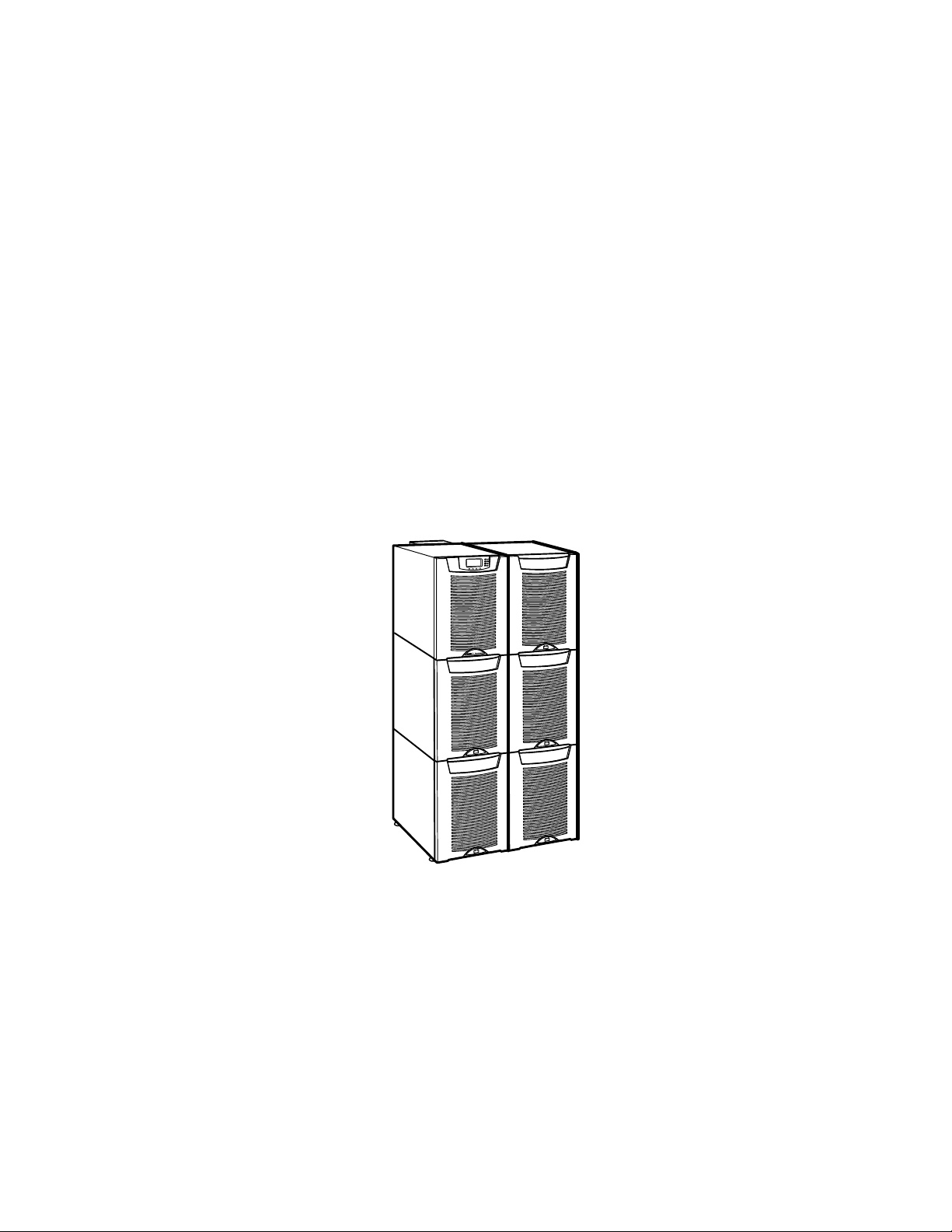
With the Powerware 9355 UPS, you can safely eliminate the effects of
electrical line disturbances and guard the integrity of your systems and
equipment. Figure 1 shows the Powerware 9355 UPS and an optional
Extended Battery Module (EBM).
Figure 1. The Powerware 9355 UPS and EBM (3-High Cabinets Shown)
EATON Powerware®9355 UPS (10/15 kVA) User’s Guide S 164201594 Rev C www.powerware.com
1

INTRODUCTION
Providing outstanding performance and reliability, the Powerware 9355
UPS’s unique benefits including the following:
S Online UPS design with pure sine wave output. The UPS filters and
regulates incoming AC power and provides consistent power to your
equipment without draining the battery.
S More wattage in less space with a 0.9 power factor—protecting more
equipment and leaving more room for expansion.
S A UPS maintenance bypass switch that provides a
Make-Before-Break (MBB) wrap-around bypass for UPS maintenance
or service without shutting down the load.
S Support for Powerware Hot Sync
®
paralleling of multiple modules for
redundancy or extra capacity.
S Input current total harmonic distortion (THD) of less than five percent,
using active input power factor correction.
S ABM
®
technology that uses advanced battery management to
increase battery service life, optimize recharge time, and provide a
warning before the end of useful battery life.
S Up to three hours of extended runtime with added EBMs.
S Advanced power management with the Software Suite CD for
graceful shutdowns and power monitoring.
S Emergency shutdown control through the remote emergency
power-off (REPO) port.
S Start-on-battery capability for powering up the UPS even if utility
power is not available.
S Standard communication options with a DB-9 serial port, relay output
contacts, and programmable signal inputs.
S Optional X-Slott cards with enhanced communication capabilities for
increased power protection and control.
2
EATON Powerware®9355 UPS (10/15 kVA) User’s Guide S 164201594 Rev C www.powerware.com

INTRODUCTION
The following options for the Powerware 9355 are available:
S Remote Monitor Panel (RMP)
The optional RMP provides monitoring of the operational status and
alarm condition of the UPS from virtually any location within the
facility. You can install multiple RMPs at remote locations to increase
your monitoring capabilities.
S Power Distribution Module (PDM)
The optional PDM comes equipped with several different types of
output receptacles.
S Parallel Tie Cabinet
An optional parallel system with up to four UPSs can be installed to
provide a parallel capacity and/or redundant system. This load sharing
system provides more capacity than a single UPS and can provide
backup, depending on the load and configuration. In addition, when
one UPS is taken out of service for maintenance or is not operating
properly, a redundant UPS continues to supply uninterrupted power
to the critical load. A parallel Powerware Hot Sync Computer Area
Network (CAN) Bridge Card provides connectivity for system
metering and operational mode control. The parallel system consists
of two to four UPSs, each with a parallel CAN Bridge Card, and a
parallel tie cabinet. Refer to the Powerware 9355 Parallel UPS
(10/15 kVA) User’s Guide for more information.
S Wall-Mounted Bypass Switch
The optional wall-mounted bypass switch is used to bypass the UPS
during maintenance or servicing, providing wrap-around bypass for
UPS service without shutting down the load.
S Input Isolation Transformer
The optional input isolation transformer is located at the bottom of a
3-high UPS model. The isolation transformer allows operation from a
480V or 600V 60-Hz source.
S Seismic Kit
The optional seismic kit secures the UPS and optional EBMs for
Zone 4 seismic installations.
EATON Powerware®9355 UPS (10/15 kVA) User’s Guide S 164201594 Rev C www.powerware.com
3

INTRODUCTION
4
EATON Powerware®9355 UPS (10/15 kVA) User’s Guide S 164201594 Rev C www.powerware.com

Chapter 2 Safety Warnings
IMPORTANT SAFETY INSTRUCTIONS
SAVE THESE INSTRUCTIONS
This manual contains important instructions that you should follow during installation and
maintenance of the UPS and batteries. Please read all instructions before operating the
equipment and save this manual for future reference.
This UPS contains LETHAL VOLTAGES. All repairs and service should be performed by
AUTHORIZED SERVICE PERSONNEL ONLY. There are NO USER SERVICEABLE PARTS
inside the UPS.
S This UPS contains its own energy source (batteries). The UPS output may carry live
voltage even when the UPS is not connected to an AC supply.
S To reduce the risk of fire or electric shock, install this UPS in a temperature and humidity
controlled, indoor environment, free of conductive contaminants. Ambient temperature
must not exceed 40°C (104°F). Do not operate near water or excessive humidity (95%
maximum).
S To reduce the risk of fire, connect only to a circuit provided with 100 amperes maximum
branch circuit overcurrent protection in accordance with the National Electrical Code,
ANSI/NFPA 70.
S Output overcurrent protection and disconnect switch must be provided by others.
DANGER
WARNING
CAUTION
S Batteries can present a risk of electrical shock or burn from high short circuit current.
Observe proper precautions. Servicing should be performed by qualified service
personnel knowledgeable of batteries and required precautions. Keep unauthorized
personnel away from batteries.
S Proper disposal of batteries is required. Refer to your local codes for disposal
requirements.
S Never dispose of batteries in a fire. Batteries may explode when exposed to flame.
EATON Powerware®9355 UPS (10/15 kVA) User’s Guide S 164201594 Rev C www.powerware.com
5

SAFETY WARNINGS
Consignes de Sécurité
CONSIGNES DE SÉCURITÉ IMPORTANTES
CONSERVER CES INSTRUCTIONS
CE MANUEL CONTIENT DES CONSIGNES DE SÉCURITÉ
IMPORTANTES
Cet onduleur contient des TENSIONS MORTELLES. Toute opération d’entretien et de
réparation doit être EXCLUSIVEMENT CONFIÉE A UN PERSONNEL QUALIFIÉ AGRÉÉ.
AUCUNE PIÈCE RÉPARABLE PAR L’UTILISATEUR ne se trouve dans l’onduleur.
S Cet onduleur renferme sa propre source d’éner gie (batteries). Les prises de sortie
S Pour réduire les risques d’incendie et de décharge électrique, installer l’onduleur
S La protection contre une surintensité pour le(s) circuit(s) de sortie de courant alternatif
S Les interrupteurs de déconnexion convenables pour le(s) circuit(s) de sortie de courant
DANGER!
WARNING
peuvent être sous tension même lorsque l’onduleur n’est pas branché sur le secteur.
uniquement à l’intérieur, dans un lieu dépourvu de matériaux conducteurs, où la
température et l’humidité ambiantes sont contrôlées. La température ambiante ne doit
pas dépasser 40 °C. Ne pas utiliser à proximité d’eau ou dans une atmosphère
excessivement humide (95 % maximum).
doit être fournie par un autre fournisseur.
alternatif doivent être fournie par un autre fournisseur.
ATTENTION!
S Les batteries peuvent présenter un risque de décharge électrique ou de brûlure par des
courts-circuits de haute intensité. Prendre les précautions nécessaires.
S Une mise au rebut réglementaire des batteries est obligatoire. Consulter les règlements
en vigueur dans votre localité.
S Ne jamais jeter les batteries au feu. L’exposition aux flammes risque de les faire
exploser.
6
EATON Powerware®9355 UPS (10/15 kVA) User’s Guide S 164201594 Rev C www.powerware.com

Advertencias de Seguridad
INSTRUCCIONES DE SEGURIDAD IMPORTANTES
GUARDE ESTAS INSTRUCCIONES
ESTE MANUAL CONTIENE INSTRUCCIONES DE SEGURIDAD
IMPORTANTES
Este SIE contiene VOLTAJES MORTALES. Todas las reparaciones y el servicio técnico deben
ser efectuados SOLAMENTE POR PERSONAL DE SERVICIO TÉCNICO AUTORIZADO. No hay
NINGUNA PARTE QUE EL USUARIO PUEDA REPARAR dentro del SIE.
S Este SIE contiene su propia fuente d e energía (las baterías). Los receptáculos de salida
pueden transmitir corriente eléctrica aun cuando el SIE no esté conectado a un
suministro de corriente alterna (c.a.).
S Para reducir el riesgo de incendio o de choque eléctrico, instale este SIE en un lugar
cubierto, con temperatura y humedad controladas, libre de contaminantes conductores.
La temperatura ambiente no debe exceder los 40°C. No trabaje cerca del agua o con
humedad excesiva (95% máximo).
S La protección contra exceso de corriente para el/los circuito(s) de CA de salida será
suministrada por terceros.
S Los interruptores de desconexión debidamente clasificados para el/los circuito(s) de CA
de salida serán suministrados por terceros.
SAFETY WARNINGS
PELIGRO
WARNING
PRECAUCIÓN
S Las baterías pueden presentar un riesgo de descargas eléctricas o de quemaduras
debido a la alta corriente de cortocircuito. P reste atención a las instrucciones
correspondientes.
S Es necesario desechar las baterías de un modo adecuado. Consulte las normas locales
para conocer los requisitos pertinentes.
S Nunca deseche las baterías en el fuego. Las baterías pueden explotar si se las expone a
la llama.
EATON Powerware®9355 UPS (10/15 kVA) User’s Guide S 164201594 Rev C www.powerware.com
7

SAFETY WARNINGS
8
EATON Powerware®9355 UPS (10/15 kVA) User’s Guide S 164201594 Rev C www.powerware.com

Chapter 3 UPS Setup
This chapter describes:
S Equipment inspection
S Floor loading and clearances
S Unloading the cabinet(s)
The instructions are intended for the chief operator/system supervisor,
electrical consultants, and installation electricians. Local regulations and
electrical code must be followed during the UPS installation.
Inspecting the Equipment
If any equipment has been damaged during shipment, keep the shipping
and packing materials for the carrier or place of purchase and file a claim
for shipping damage. If you discover damage after acceptance, file a
claim for concealed damage.
To file a claim for shipping damage or concealed damage: 1) File with
the carrier within 15 days of receipt of the equipment; 2) Send a copy of
the damage claim within 15 days to your service representative.
NOTE Check the battery recharge date on the packaging label. If the date has expired and
the batteries were never recharged, do not use the UPS. Contact your service representative.
EATON Powerware®9355 UPS (10/15 kVA) User’s Guide S 164201594 Rev C www.powerware.com
9

UPS SETUP
Floor Loading
When planning the installation, consider the UPS weight for floor
loading. The strength of the installation surface must be adequate for
point and distributed loadings. The approximate weights are shown in
the following table.
Standard Model Floor Loadings (2-High/3-High Cabinets)
Clearances
Powerware 9355
2-High UPS 381 lb (173 kg) 95 (6.7)
3-High UPS-32 587 lb (266 kg) 147 (10.3)
3-High UPS-64 619 lb (281 kg) 155 (10.9)
2-High EBM 480 lb (218 kg) 120 (8.4)
3-High EBM 710 lb (322 kg) 178 (12.5)
Maximum
Weight
Point Loading
2
lb/in
(kg/cm2)
The following clearances are recommended for the Powerware 9355
UPS:
From Front of Cabinet 36” (91.4 cm) working space
From Back of Cabinet 6” (15.2 cm) without PDM installed; with PDM installed,
clearance determined by customer-supplied mating plug
10
EATON Powerware®9355 UPS (10/15 kVA) User’s Guide S 164201594 Rev C www.powerware.com
Unloading the Cabinet(s)
The following tools are required for unloading the cabinet(s):
S 15 mm wrench or socket
S 7 mm nut driver or socket
The UPS and EBM are heavy (see page 10). Unloading the cabinets requires at least two
people to safely remove the cabinets from t he pallet.
To unload three-high cabinets or two-high EBMs, continue to the
following section. To unload two-high UPS cabinets, proceed to page 15.
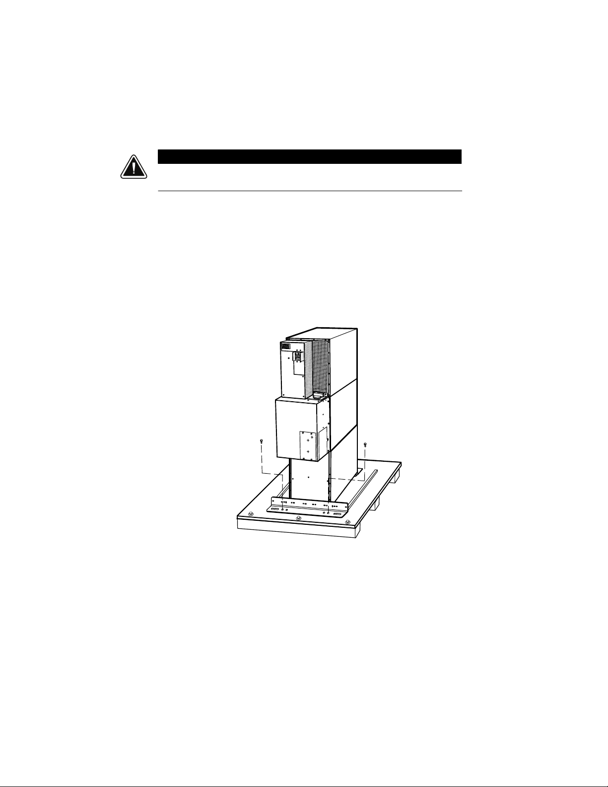
Three-High Cabinets or Two-High EBMs
To remove a three-high cabinet or a two-high EBM from the shipping
pallet:
1. Remove the two M10 bolts securing the stabilizing bracket to the
pallet (see Figure 2).
UPS SETUP
CAUTION
M10 Bolts
Figure 2. Removing the Stabilizing Bracket Bolts
EATON Powerware®9355 UPS (10/15 kVA) User’s Guide S 164201594 Rev C www.powerware.com
11

UPS SETUP
2. Remove the four M4 screws securing the stabilizing bracket to the
cabinet rear panel and remove the bracket (see Figure 3). Retain the
hardware for later use.
NOTE Be sure to retain the stabilizing bracket and hardware for later re-assembly onto the
cabinet.
3. Remove the front cover from the bottom cabinet to access the
front shipping bracket.
Press and release the handle latch at the bottom of the cover and
then lift the cover up and off the cabinet.
4. Remove the three M10 bolts securing the rear shipping pad to the
pallet and remove the shipping pad.
12
EATON Powerware®9355 UPS (10/15 kVA) User’s Guide S 164201594 Rev C www.powerware.com
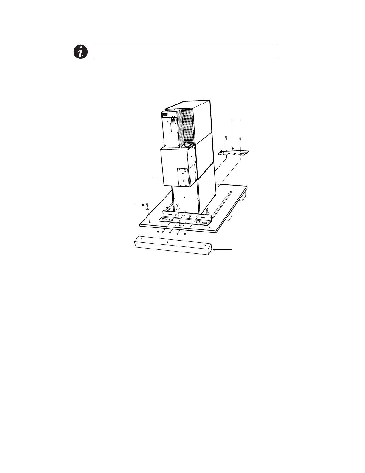
UPS SETUP
NOTE Hold the back of the cabinet so that the bolts can be removed easily without the
cabinet rolling backward.
5. Remove the two M10 bolts securing the front shipping bracket and
remove the bracket.
If needed, adjust the leveling feet to release the bracket.
Front Shipping
Bracket
M10 Bolts
Stabilizing Bracket
M10 Bolts
M4 Screws
Shipping Pad
Figure 3. Removing the Brackets and Shipping Pad
6. Reinstall the front cover removed in Step 3.
Hang the top edge of the cover on the cabinet first, then lower the
bottom edge and snap into place.
EATON Powerware®9355 UPS (10/15 kVA) User’s Guide S 164201594 Rev C www.powerware.com
13
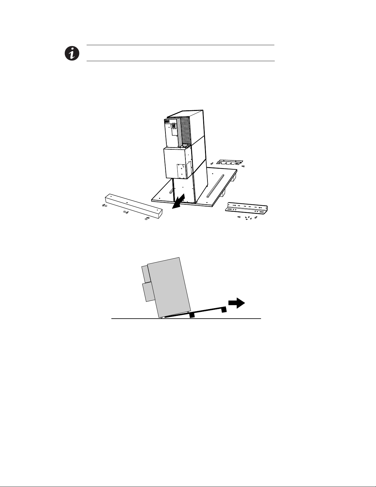
UPS SETUP
NOTE Be sure to support the front and back of the cabinet when rolling it off the pallet to
prevent tipping.
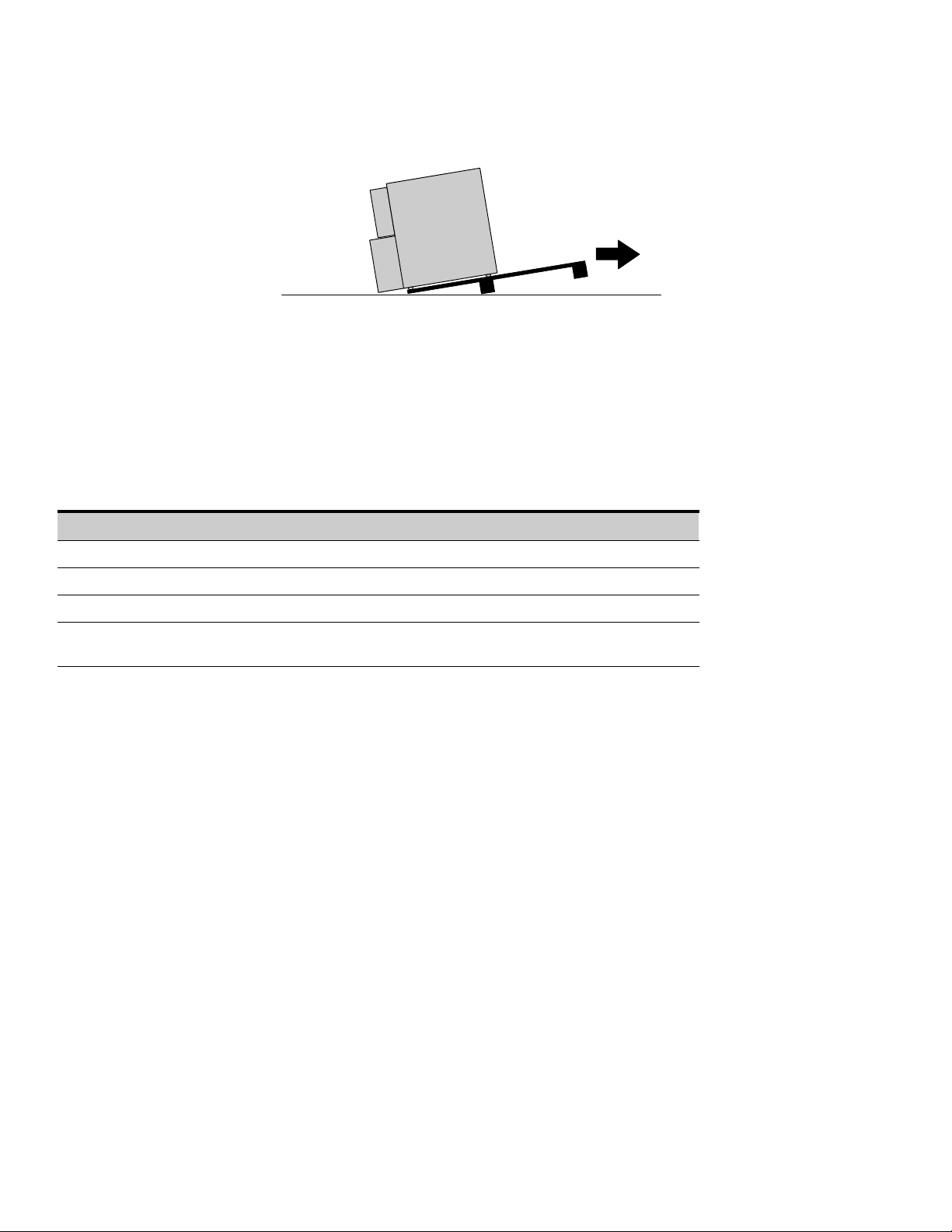
7. Slowly roll the cabinet toward the rear of the pallet. Once the pallet
tilts, continue rolling the cabinet down the pallet until the cabinet
touches the floor (see Figure 4).
If needed, adjust the leveling feet so that the cabinet will roll.
14
Figure 4. Unloading the Cabinet
8. With the cabinet supported, slowly pull the pallet away from the
cabinet (see Figure 5).
Figure 5. Removing t he Pallet
9. Roll the cabinet to the desired location.
10. Continue to “Selecting an Installation Option” on page 18.
EATON Powerware®9355 UPS (10/15 kVA) User’s Guide S 164201594 Rev C www.powerware.com
UPS SETUP
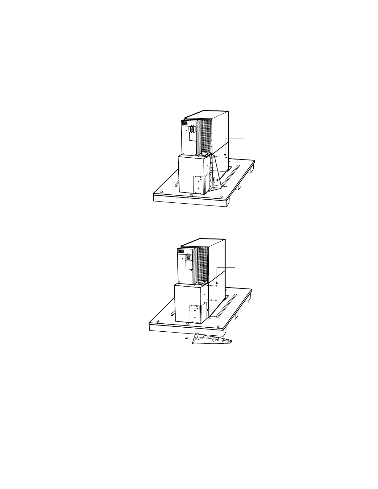
Two-High UPS Cabinets
To remove a two-high UPS from the shipping pallet:
1. Remove the M10 bolt securing the vertical bracket to the pallet (see
Figure 6).
2. Remove and retain the three M4 screws securing the vertical
bracket to the UPS. Remove the vertical bracket.
M4 Screws
M10 Bolt
Figure 6. Removing t he Vertical Bracket
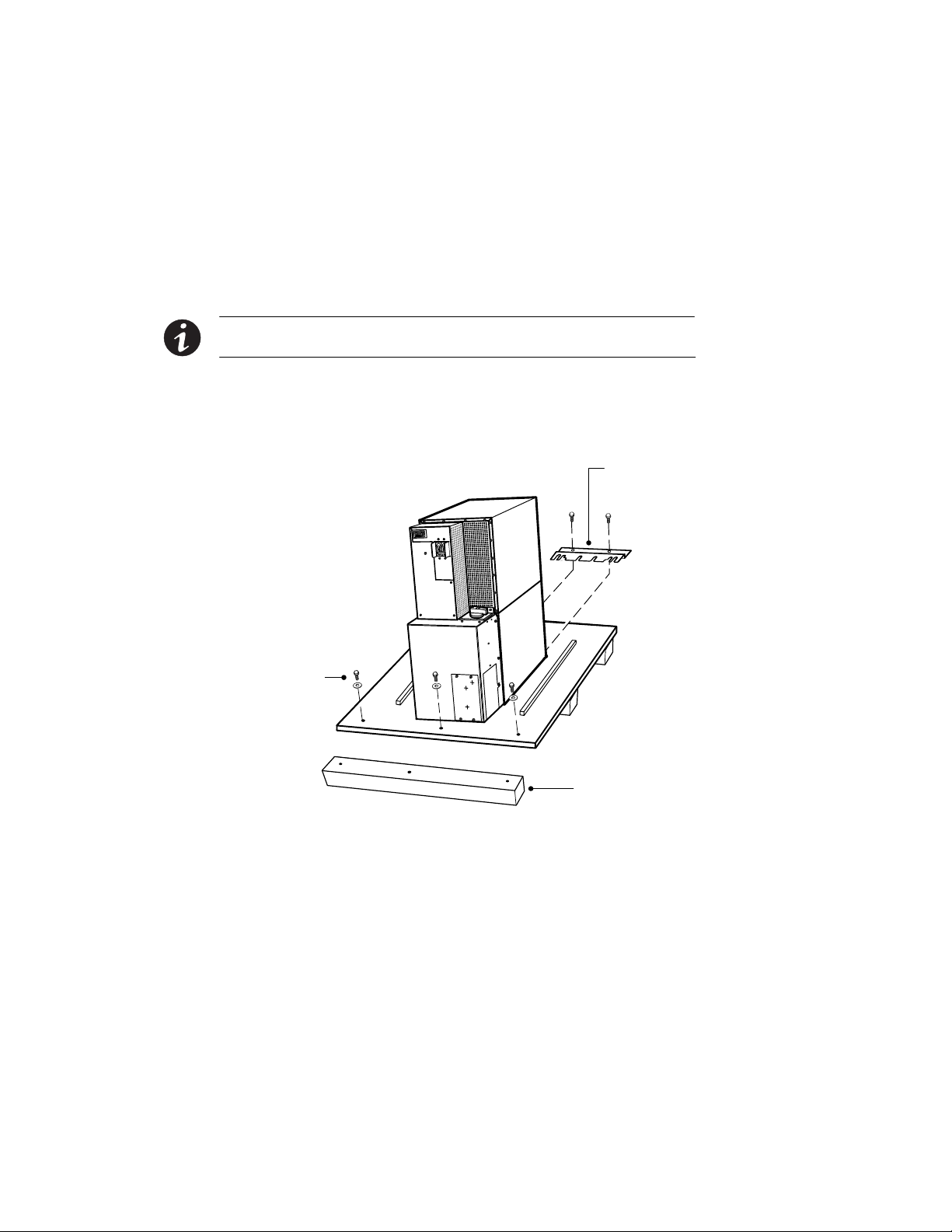
3. Reinstall the M4 screws to the UPS (see Figure 7).
M4 Screws
Figure 7. Reinstalling the M4 Screws
EATON Powerware®9355 UPS (10/15 kVA) User’s Guide S 164201594 Rev C www.powerware.com
15
UPS SETUP
4. Repeat Steps 1 through 3 to remove the vertical bracket on the
other side.
5. Remove the front cover from the bottom cabinet to access the
front shipping bracket.
Press and release the handle latch at the bottom of the cover and
then lift the cover up and off the cabinet.
6. Remove the three M10 bolts securing the rear shipping pad to the
pallet and remove the shipping pad (see Figure 8).
NOTE Hold the back of the cabinet so that the bolts can be removed easily without the
cabinet rolling backward.
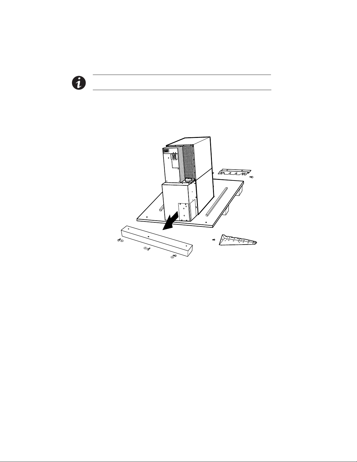
7. Remove the two M10 bolts securing the front shipping bracket and
remove the bracket.
If needed, adjust the leveling feet to release the bracket.
Front Shipping
Bracket
16
M10 Bolts
M10 Bolts
Shipping Pad
Figure 8. Removing the Front Shipping Bracket and Shipping Pad
EATON Powerware®9355 UPS (10/15 kVA) User’s Guide S 164201594 Rev C www.powerware.com
UPS SETUP
8. Reinstall the front cover removed in Step 5.
Hang the top edge of the cover on the cabinet first, then lower the
bottom edge and snap into place.
NOTE Be sure to support the front and back of the cabinet when rolling it off the pallet to
prevent tipping.
9. Slowly roll the cabinet toward the rear of the pallet. Once the pallet
tilts, continue rolling the cabinet down the pallet until the cabinet
touches the floor (see Figure 9).
If needed, adjust the leveling feet so that the cabinet will roll.
Figure 9. Unloading the Cabinet
EATON Powerware®9355 UPS (10/15 kVA) User’s Guide S 164201594 Rev C www.powerware.com
17
UPS SETUP
10. With the cabinet supported, slowly pull the pallet away from t he
cabinet (see Figure 10).
11. Roll the cabinet to the desired location.
12. Continue to the following section, “Selecting an Installation
Option.”
Selecting an Installation Option
You are now ready to install the Powerware 9355 UPS. Select one of the
following installation options according to your UPS configuration:
Figure 10. Removing the Pallet
UPS Configuration Installation Chapter
UPS only Chapter 4, “UPS Installation” on page 19
UPS with an optional input isolation transformer Chapter 4, “UPS Installation” on page 19
UPS with an optional wall-mounted bypass switch Chapter 5, “Wall-Mounted Bypass Switch Installation” on page 29
Parallel UPS configuration Refer to the Powerware 9355 Parallel UPS (10/15 kVA) User’s
Guide
.
18
EATON Powerware®9355 UPS (10/15 kVA) User’s Guide S 164201594 Rev C www.powerware.com

Chapter 4 UPS Installation
The Powerware 9355 has the following power connections:
S 3-phase (L1, L2, and L3), neutral, and ground connection for
rectifier/bypass input
S 3-phase (L1, L2, and L3), neutral, and ground connection for load
output
The nominal input/output voltages are:
S 120/208 or 127/220 Vac
S 480V or 600V 60-Hz input is available using the optional input isolation
transformer module
Output overcurrent protection and disconnect switch must be provided
by others.
Figure 15 through Figure 17 beginning on page 25 show the oneline
diagrams.
Only qualified service personnel (such as a licensed electrician) should perform the UPS
installation and initial startup. Risk of electrical shock.
WARNING
To hardwire the UPS:
1. Verify that the electrical connections to the installation site have
been properly installed.
2. A wall-mounted, user-supplied, readily-accessible disconnection
device must be incorporated in the input wiring.
Compare the circuit breaker ratings to the ones in Table 1 on
page 22.
NOTE To accommodate the feature of easy system expandability, it is recommended that
initial installation of the Powerware 9355 UPS contain wiring to support the maximum
capacity of the UPS cabinet.
3. Switch off utility power to the distribution point where the UPS will
be connected. Be absolutely sure there is no power.
EATON Powerware®9355 UPS (10/15 kVA) User’s Guide S 164201594 Rev C www.powerware.com
19
UPS INSTALLATION
4. Determine your equipment’s grounding requirements according to
your local electrical code.
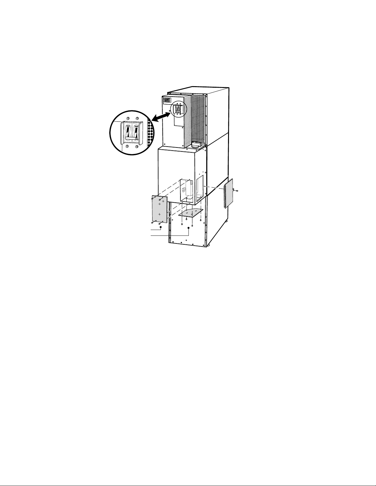
5. Verify that the UPS battery circuit breaker is in the OFF position
(see Figure 11).
Battery Circuit Breaker
20
UPS Wiring
Access Cover
Conduit Landing Plates
Figure 11. UPS Rear View (3-High Shown)
6. For UPS only installations, continue to Step 7; for UPS installations
with an input isolation transformer, proceed to Step 10.
7. Remove the UPS wiring access cover and one of the conduit
landing plates and retain (see Figure 11).
8. Punch two holes in the conduit landing plate for the input and
®
output conduit using a Greenlee
punch or similar device.
9. Proceed to Step 12.
EATON Powerware®9355 UPS (10/15 kVA) User’s Guide S 164201594 Rev C www.powerware.com
UPS INSTALLATION
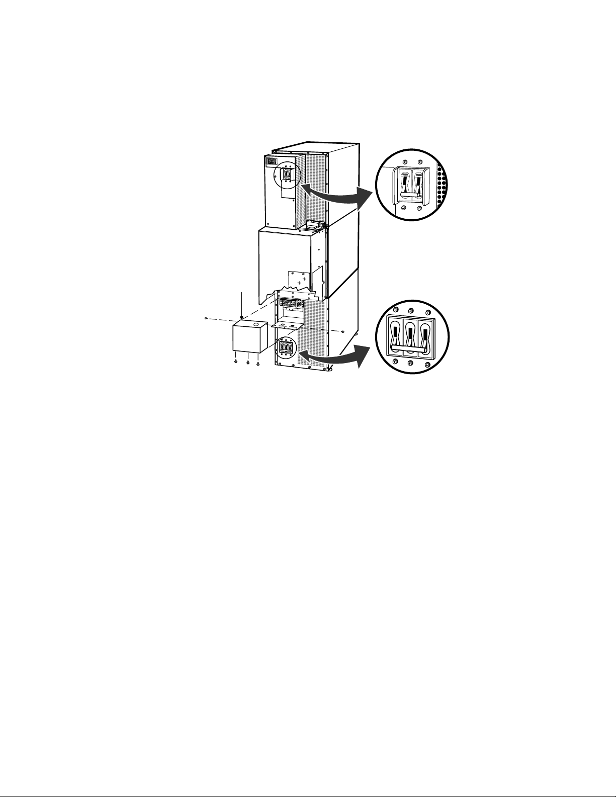
10. Verify that the input circuit breaker is in the OFF position (see
Figure 12).
11. Remove the input isolation transformer wiring access cover and
retain.
Battery Circuit Breaker
Input Isolation
Transformer
Wiring Access Cover
Input Circuit Breaker
Figure 12. UPS with Input Isolation Transformer Rear View
12. Hardwire the input, output, and ground terminations for t he UPS or
input isolation transformer. See Table 1 for wiring specifications.
For a detailed view of the terminal block, see Figure 13 or Figure 14
on page 23.
EATON Powerware®9355 UPS (10/15 kVA) User’s Guide S 164201594 Rev C www.powerware.com
21

UPS INSTALLATION
p
120lbin
p
120lbin
p
120lbin
p
120lbin
NOTE Input neutral must be wired for proper operation. Failure to connect an input neutral
will void the warranty.
NOTE The Powerware 9355 UPS is a single-feed UPS only.
Table 1. Terminal Block Wiring
10 kVA
Input Voltage
208
220
480 (with transformer) 20A
600
(with transformer) 20A
208
220
480 (with transformer)
600
(with transformer)
15 kVA
Input Voltage
208
220
480 (with transformer) 30A
600 (with transformer) 25A
208
220
480 (with transformer)
600
(with transformer)
1
Use only 90°C-rated copper wire. Minimum wire size is based on 120/208 full load ratings applied to NEC Code
Wire
Function
Input
Output
Wire
Function
Input
Output
Input Circuit
Breaker Size
45A
45A
Input Circuit
Breaker Size
60A
60A
L1, L2, L3, N
Wire Size
1
Ground
Wire Size
Tightening
1
Torque
Conduit Size
(Number of Conduits)
6AWG 10 AWG
8AWG 10 AWG
12 AWG 12 AWG
(13.5 Nm)
1.00” conduit (1)
12 AWG 14 AWG
8AWG 10 AWG
8AWG 10 AWG
8AWG 10 AWG
(13.5 Nm)
1.00” conduit (1)
8AWG 10 AWG
L1, L2, L3, N
Wire Size
1
Ground
Wire Size
Tightening
1
Torque
Conduit Size
(Number of Conduits)
4AWG 10 AWG 1.25” conduit (1)
4AWG 10 AWG
10 AWG 10 AWG
(13.5 Nm)
1.25” conduit (1)
1.00” conduit (1)
10 AWG 10 AWG 1.00” conduit (1)
6AWG 10 AWG
6AWG 10 AWG
6AWG 10 AWG
(13.5 Nm)
1.00” conduit (1)
6AWG 10 AWG
2, 3
2, 3
Table 310-16. Code may require a larger AWG size than shown in this table because of temperature, number of
conductors in the conduit, or long service runs. Follow local requirements.
2
Per NEC article 300-20(a), all three-phase conductors must be run in the same conduit. Neutral and ground must be
run in the same conduit as the phase conductors.
3
Conduit is sized to accommodate one neutral conductor the same size as the phase conductor and one #8 AWG
ground conductor. If two neutral conductors or an oversized neutral conductor are to be installed, check the size of the
conduit needed to accommodate the extra wire or size and use that conduit size in place of the conduit size listed.
Conduit sizes were chosen from NEC Table C1, type letters RHH, RHW, RHW-2, TW, THW, THHW, THW-2.
22
EATON Powerware®9355 UPS (10/15 kVA) User’s Guide S 164201594 Rev C www.powerware.com
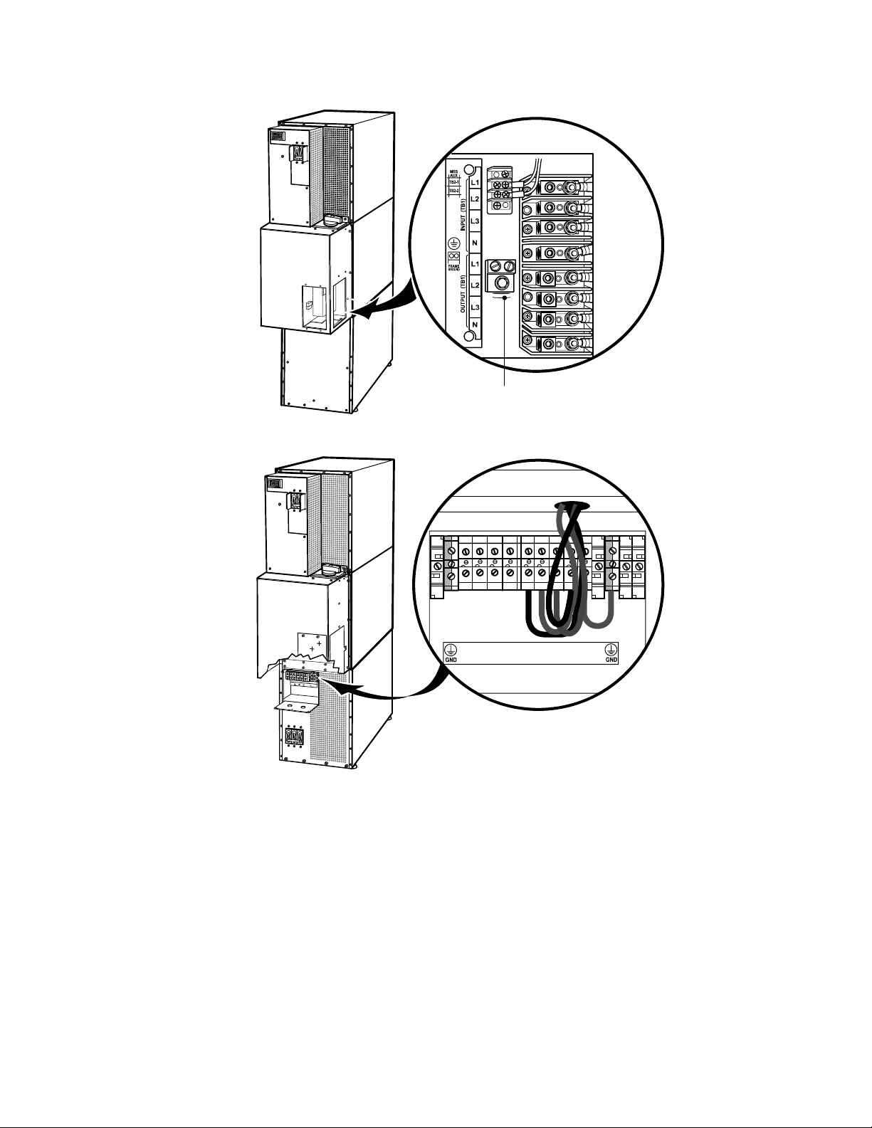
UPS INSTALLATION
Ground
Figure 13. UPS Terminal Block (3-High Shown)
L1L2L3 N
INPUT
L1
L3
L2
OUPUT
N
N
Figure 14. Input Isolation Transformer Terminal Block
EATON Powerware®9355 UPS (10/15 kVA) User’s Guide S 164201594 Rev C www.powerware.com
23

UPS INSTALLATION
13. For UPS only installations, replace the UPS wiring access cover and
conduit landing plate.
For UPS installations with an input isolation transformer, replace the
transformer wiring access cover.
14. Continue to “Stabilizing the Cabinet” on page 41 to complete the
UPS installation.
24
EATON Powerware®9355 UPS (10/15 kVA) User’s Guide S 164201594 Rev C www.powerware.com
 Loading...