

Eaton SC-UN-FT Installation Manual
Installation Instructions
Model # SC-UN-FT
Universal Source Controller - Feed Through
INS #

Contents
Contents
Description Page
Introduction ...................................................................3
Welcome ...................................................................3
Range Overview ..............................................................3
Cabinet Dimensions .........................................................3
Specifications ................................................................5
Safety .......................................................................5
Please Read this First. . . . . . . . . . . . . . . . . . . . . . . . . . . . . . . . . . . . . . . . . . . . . . . . . . . . . . . . . . 5
Important Points for Consideration ...............................................5
Ambient Atmosphere Requirements ............................................6
Mounting ..................................................................... 6
Location and Spacing ..........................................................6
Mounting Holes ..............................................................7
Standard Weights ........................................................... 7
Accessing the Mounting Holes .................................................8
Supply Wiring ................................................................. 8
Wiring Flow ................................................................. 8
Single Phase Supply ...........................................................9
Connecting the Supply ....................................................... 9
Max. Wire Gauge for Input Lugs (1 Phase) .......................................9
Three Phase Supply ...........................................................9
Connecting the Supply ....................................................... 9
Max. Wire Gauge for Input Lugs (3 Phase) .......................................9
Phase Distribution to Circuits ................................................. 10
Supply to Internal Circuitry ................................................... 10
Load Wiring .................................................................. 10
High Voltage Load Wiring ......................................................10
Total Load Per Channel ...................................................... 11
Load Wire Gauges ......................................................... 11
Earth Connections .......................................................... 11
High Voltage Load Wiring Flows ................................................. 11
Typical Load Connections .................................................... 11
Low Voltage Load Wiring ...................................................... 12
Low Voltage Load Wiring Flows ............................................... 12
Indicators ................................................................. 12
Control Wiring ................................................................ 13
Multiple Control Protocols ..................................................... 13
Termination ............................................................... 13
Control Panel Operation ........................................................ 14
Using The Control Panel ....................................................... 14
Accessing the Operation Menu ............................................... 15
Menu Navigation ........................................................... 15
Overriding Channels ........................................................ 15
Setting the Time and Date ...................................................15
Viewing Power Data Readings ................................................ 16
2
Universal Source Controller - Feed Through
Introduction
Introduction
Welcome
The iLumin Universal Source Controller range from Eaton’s
Cooper Controls Business has been designed to provide
maximum flexibility in both installation and operation.
Every model in the range can accept a variety of industry
standard control options, from iCANbus to DMX, from
ethernet to RS-485. Similarly, every model can drive a wide
range of lighting loads, from incandescents to dimmable
fluorescents, from non-dim apparatus to DALI digital
modules.
Much care and attention has been applied to the installation
and maintenance of the Universal Source Controllers.
Each model provides clear, logical cable routing and every
high voltage channel is controlled by an individual, easy to
replace dimmer card.
Range Overview
Each model is specified using a part number in the following
format:
SC 120 06 UN 1P FT
Product
SC = Source Controller
Panel Feed
FT = Feed Through
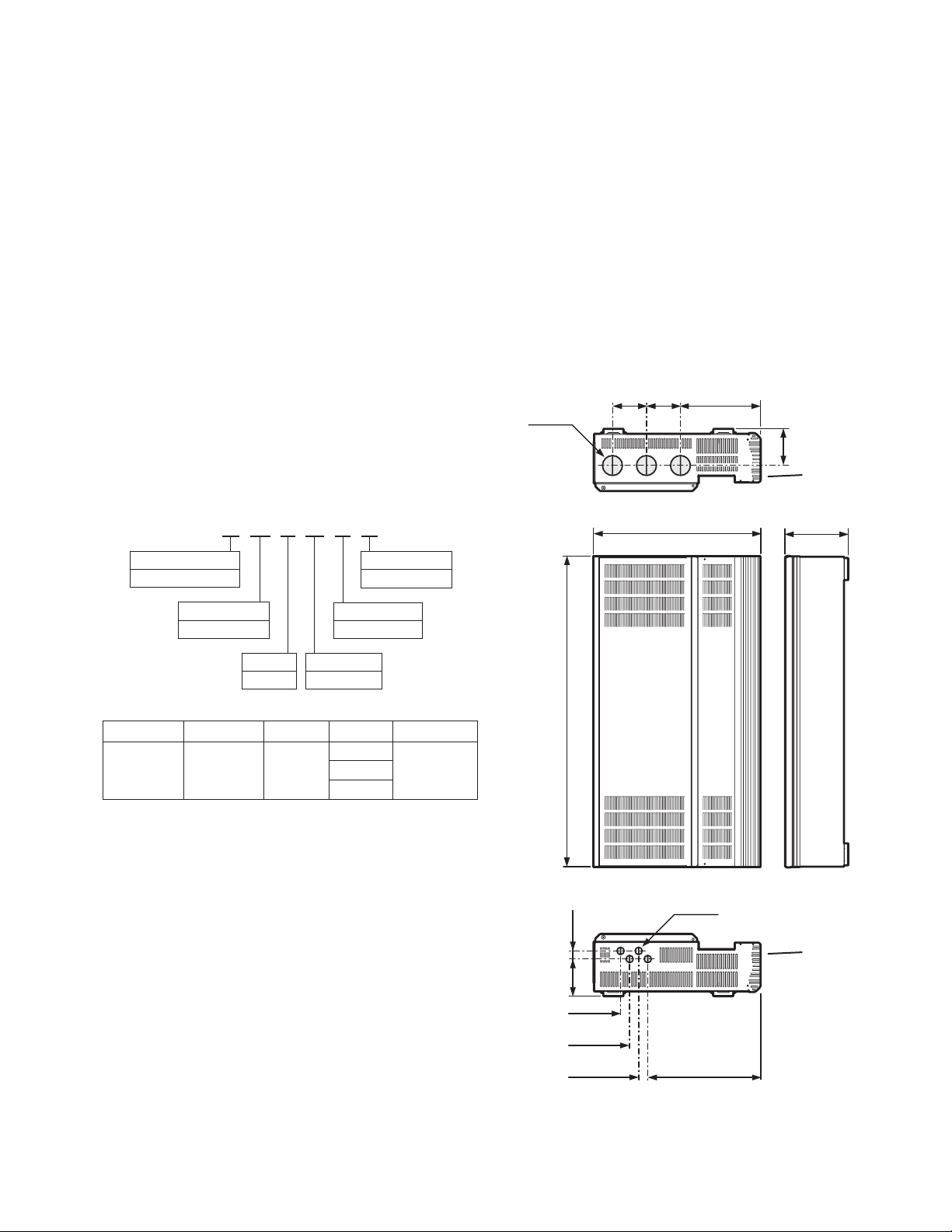
Cabinet Dimensions
Three overall cabinet sizes are available as shown on this
and the following pages.
6 Circuit Cabinet
Weight
Packed: 100 lbs (45 Kg)
Unpacked: 88 lbs (40 Kg)
9.78 in.
(248.5 mm)
4.13 in.
(105 mm)
20.3 in.
(517 mm)
(105 mm)
4.45 in.
(113 mm)
Knockouts for
Supply and Load
Wiring Only
7.6 in.
(193 mm)
4.13 in.
Ø 2.42 in.
61.5 mm
Supply Voltage
277-120 to 277 VAC
Channels
06, 12, 24
Model Number Supply Voltage Supply Type Circuits Maximum Load
SC277-06-UN-1P-FT
SC277-12-UN-1P-FT
SC277-24-UN-3P-FT
120 to 277 VAC 1 Phase
Supply Type
1P = Single Phase
Type
UN = Universal
6
16A per Channel12
24
0.98 in.
(25 mm)
4.53 in.
(115 mm)
37.2 in.
(945 mm)
1.1 in.
(28 mm)
1.1 in.
(28 mm)
1.1 in.
(28 mm)
Ø 0.89 in.
(22.5 mm)
Knockouts for
Low Voltage
Control Wiring
Only
13.76 in.
(349.5 mm)
Universal Source Controller - Feed Through
3
Introduction
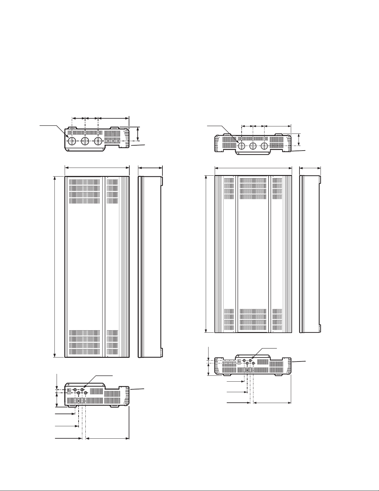
12 Circuit Cabinet
Weight
Packed: 160 lbs (72 Kg)
Unpacked: 132 lbs (60 Kg)
4.13 in.
(105 mm)
Ø 2.42 in.
61.5 mm
(517 mm)
4.13 in.
(105 mm)
20.3 in.
9.78 in.
(248.5 mm)
4.45 in.
(113 mm)
Knockouts for
Supply and Load
Wiring Only
7.6 in.
(193 mm)
24 Circuit Cabinet
Weight
Packed (24): 220 lbs (100 Kg)
Unpacked (24): 200 lbs (90 Kg)
4.13 in.
Ø 2.42 in.
61.5 mm
(105 mm)
4.13 in.
27.8 in.
(707 mm)
9.78 in.
(248.5 mm)
(105 mm)
4.45 in. (113 mm)
Knockouts for
Supply and Load
Wiring Only
7.6 in.
(193 mm)
0.98 in.
(25 mm)
4.53 in.
(115 mm)
56.7 in.
(1440 mm)
1.1 in.
(28 mm)
1.1 in.
(28 mm)
1.1 in.
(28 mm)
Ø 0.89 in.
(22.5 mm)
13.76 in.
(349.5 mm)
Knockouts for
Low Voltage
Control Wiring
Only
0.98 in.
(25 mm)
4.53 in.
(115 mm)
56.7 in.
(1440 mm)
1.1 in.
(28 mm)
1.1 in.
(28 mm)
1.1 in.
(28 mm)
Ø 0.89 in.
(22.5 mm)
Knockouts for
Low Voltage
Control Wiring
Only
13.76 in.
(349.5 mm)
4
Universal Source Controller - Feed Through

Safety
Specifications
The numerous models within the Universal Source
Controller range share the following key specifications.
Information specific to each cabinet model are provided
elsewhere throughout this guide.
All channels provide switched (non-dim) and dimmed high
voltage load control as standard
Leading-edge triac dimmer engines capable of
withstanding repetitive inrush currents of 50 times
operating current without impacting lifetime
All dimming and switching circuitry for every channel
located on individual boards for quick and easy swap-out,
if necessary
Voltage and frequency compensation to maintain light
level during supply fluctuations
Power monitoring for each circuit and the total panel
Bypass jumpering fitted as standard to protect circuits
and allow work lighting during installation
Selectable low voltage load control available per channel
for dimmable ballast control
Low maintenance and quiet operation thanks to fanless,
convection cooled operation
Support for multiple control protocols: iCAN for links
to multiple control sources; DMX512A for links with
entertainment systems; RS-485 for integration with
building management schemes and ethernet for
connection to a variety of systems
Dual volt-free switch inputs, with programmable
responses, for integration with emergency control
devices, building management systems, etc
Compact wall mounted design with easy access to all
internal items and lockable front panel door for added
security
Intuitive control panel provides straightforward
programming and configuration of the system. The control
panel allows a base level installation to be configured
without the use of separate PC programming
Safety
Please Read This First
The Universal Source Controllers are designed, built and
tested to strict safety regulations. By following the steps
listed below and elsewhere within this guide, you can
ensure safe installation and operation of these controller
units.
The Universal Source Controllers must be installed only
by a qualified electrician
The installation must comply with the appropriate
electrical codes and regulations in force in your area
The Universal Source Controllers are designed for indoor
installation and use only. The units can, however, be used
to control appropriately certified exterior lighting fixtures
Ensure that all wiring used conforms fully to local
specifications and is sufficiently rated for the installation
All new wiring must be fully verified before applying power
The high voltage supply should be fed to the Universal
Source Controller via an external isolation breaker with
sufficient capacity for the planned installation
All Universal Source Controllers exceed the weight limit
for one person lifting - always use at least two people
when lifting and mounting the units
Do not mix load types within a single channel (e.g. 120V
tungsten and low voltage ballast control)
Ensure that the supply is fully isolated at an external
breaker before removing the chassis covers. Test that
power has been removed before starting to handle
conductors
Ensure that high voltage and low voltage wiring remains
separate
Each dimmer channel should be protected by its own
dedicated external circuit breaker.
Important Points For Consideration
The Universal Source Controllers must be mounted flush
with the wall, do not recess the controller chassis
Upper and lower raceways must not be located within
8 inches (200 mm) of the upper and lower panels of the
Universal Source Controller. Use suitable conduits and
couplers to link the raceways to the controller chassis
Allow adequate space for future maintenance of the unit.
Do not install in a location that will later be difficult to
access
The Universal Source Controllers are designed to be
mounted vertically
During operation, the Universal Source Controllers
will produce audible noise caused by electrical noise
suppression circuitry and also the circuit relays within
the unit. The noise is a low level buzz that varies with
the level of dimming and also clicks when relays are
energised. Take these matters into consideration when
deciding on a suitable mounting position.
Universal Source Controller - Feed Through
5
Mounting
The hinged cover must be unscrewed and removed from
the front cover when the Universal Source Controller
operates at full load in a high ambient environment
Ambient Atmosphere Requirements
Temperature 320 F to 1040 F (00 C to +400 C)
Humidity 0 to 95% non-condensing
Mounting
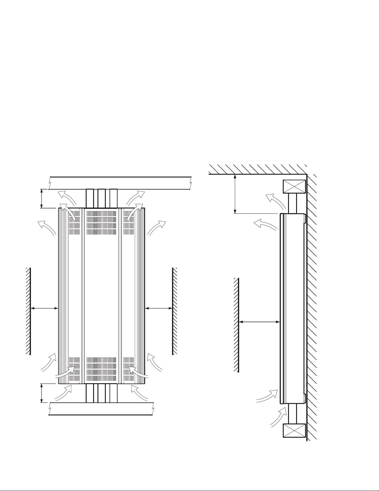
Location and Spacing
The Universal Source Controller models are all fully
convection cooled, therefore it is vitally important to ensure
that each unit is installed in a ventilated location that
permits sufficient airflow and provides the correct ambient
conditions.
Ensure that the minimum distances to walls and other
equipment shown in the diagrams below are maintained.
Also ensure that the stated ambient atmosphere
requirements are not exceeded.
Refer to ‘Important points for consideration’ when choosing
a mounting location.
8 in.
(200 mm)
Minimum
(130 mm)
Minimum
5 in.
Upper Raceway
Airflow
5 in.
(130 mm)
Minimum
14 in.
(360 mm)
Minimum
Distance
to Ceiling
14 in.
(360 mm)
Minimum
for Door
Access and
Cooling
8 in.
(200 mm)
Minimum
6
Airflow
Lower Raceway
Universal Source Controller - Feed Through
Airflow
 Loading...