


Get parts online at
Pièces détachées en ligne à Obtenga piezas en línea en www.GetEarthquake.com
Includes Model:
Inclut le modèle, Incluye el modelo
MC43
CAUTION ICON R1
READ OM ICON R1
Operator’s Manual
Original Operating Instructions
Manuel de l’utilisateur Manual del operador
MC43
2-Cycle Cultivator
Motobineuse 2 temps Cultivador de 2 ciclos
P/N: 26478
ECN: 11296 REV1: 10/01/16 © 2016 Ardisam, Inc.
All Rights Reserved Tous droits réservés Todos los derechos reservados
Operator’s Manual
MC43 2-Cycle Cultivator
INTRODUCTION
Thank you for purchasing a cultivator from Earthquake®. We have worked to ensure that this cultivator meets the highest standards for usability and durability. With proper care, your cultivator will provide many years of service.
Please read this entire manual before installation and use. Earthquake® reserves the right to change, alter or improve the product and this document at any time without prior notice.
CONTENTS |
|
Introduction/Content/Registration and Service................................................................................................................................................................ |
2 |
Warnings and Safety Precautions....................................................................................................................................................................................... |
3-6 |
Operation Precautions/Maintenance and Storage Precautions.................................................................................................................................. |
6 |
Burns and Fires/Safety Decals.............................................................................................................................................................................................. |
6-7 |
Features............................................................................................................................................................................................................................................ |
8 |
Unpacking and Assembly.......................................................................................................................................................................................................... |
9 |
Operation................................................................................................................................................................................................................................... |
9-12 |
Maintenance and Storage................................................................................................................................................................................................ |
12-14 |
Troubleshooting and Repair............................................................................................................................................................................................ |
14-15 |
Illustrated Parts Breakdown............................................................................................................................................................................................. |
16-20 |
15073 Border-Edger Kit Installation (Optional Accessory)........................................................................................................................................... |
21 |
DK43 Dethatcher Kit Installation (Optional Accessory)................................................................................................................................................ |
22 |
Warranty......................................................................................................................................................................................................................................... |
23 |
REGISTRATION AND SERVICE
Record the product model number and serial number in the space provided for easy reference when ordering parts or requesting technical support. Excluding emissions-related warranty items, the warranty is valid only if the completed registration is received by Ardisam within 30 days of purchase. (SEE WARRANTY SECTION FOR MORE INFORMATION) You can register your warranty online by visiting www.earthquake.com, or by mailing it to: Ardisam Inc, 1160 8th Avenue, Cumberland, WI 54829. You may also call our Customer Service department at (800) 345-6007 Mondays through Fridays from 8 a.m. to 5 p.m. CST.
SERIAL |
NUMBER |
DECAL |
OWNERSHIP RECORDS
Owner’s Name:
Owner’s Address:
City: |
State/Province: |
Zip Code/Postal Code: |
Model Number: |
Serial Number: |
|
Date of Purchase: |
|
|
Notes: |
|
|
Read and keep this manual for future reference. This manual contains important information on SAFETY, ASSEMBLY, OPERATION, AND MAINTENANCE. The owner must be certain that all the product information is included with the unit. This information includes the MANUAL, the REPLACEMENT PARTS and the WARRANTIES. This information must be included to make sure state laws and other laws are followed. All persons to whom rent/loan this unit must have access to and understand this information. This manual should remain with the product even if it is resold.
2 |
Check for parts online at www.getearthquake.com or call 800-345-6007 M-F 8-5 |

Operator’s Manual
MC43 2-Cycle Cultivator
WARNINGS AND SAFETY PRECAUTIONS
Owner’s Responsibility
Accurate assembly and safe and effective use of the machine is the owner’s responsibility.
•Read and follow all safety instructions.
•Carefully follow all assembly instructions.
•Maintain the machine according to directions and schedule included in this Earthquake operator’s manual.
•Ensure that anyone who uses the machine is familiar with all controls and safety precautions.
Special Messages
Your manual contains special messages to bring attention to potential safety concerns, machine damage as well as helpful operating and servicing information. Please read all the information carefully to avoid injury and machine damage.
NOTICE
NOTICE INDICATES YOUR EQUIPMENT CAN BE DAMAGED IF THE SAFETY INSTRUCTIONS THAT FOLLOW THIS SIGNAL WORD ARE NOT OBEYED.
 CAUTION
CAUTION INDICATES A HAZARD WHICH, IF NOT AVOIDED, COULD RESULT IN PERSONAL INJURY AND/OR PROPERTY DAMAGE.
 WARNING
WARNING INDICATES A HAZARD WHICH, IF NOT AVOIDED, COULD RESULT IN DEATH OR SERIOUS INJURY AND/OR PROPERTY DAMAGE.
NOTE: General information is given throughout the manual that may help the operator in the operation or service of the machine.
THIS SYMBOL POINTS OUT IMPORTANT SAFETY INSTRUCTIONS WHICH, IF NOT FOLLOWED, COULD ENDANGER YOUR PERSONAL SAFETY. READ AND FOLLOW ALL INSTRUCTIONS IN THIS MANUAL BEFORE ATTEMPTING TO OPERATE THIS EQUIPMENT.
Before Operating Engine:
Please read this section carefully. Read entire operating and maintenance instructions for this product. Failure to follow instructions could result in damage to personal property, serious injury or death. Operate the machine according to the safety instructions outlined here and inserted throughout the text. Anyone who uses this machine must read the instructions and be familiar with the controls.
Intended Use / Foreseeable Misuse
IMPORTANT: This is a motorized rotary cultivator that works the soil by means of rotating tines. It is pedestrian-controlled, but not self-propelled, with a gasoline-fueled internal combustion engine to power the tines. It shall not be used for any other purpose.
 DANGER
 DANGER
DANGER INDICATES A HAZARD WHICH, IF NOT AVOIDED, WILL CERTAINLY RESULT IN DEATH OR SERIOUS INJURY AND/OR PROPERTY DAMAGE.
IMPORTANT
IMPORTANT INDICATES HELPFUL INFORMATION FOR PROPER ASSEMBLY, OPERATION, OR MAINTENANCE OF YOUR EQUIPMENT.
 WARNING
CALIFORNIA PROPOSITION 65 WARNING
ENGINE EXHAUST FROM THIS PRODUCT CONTAINS CHEMICALS KNOWN TO THE STATE OF CALIFORNIA TO CAUSE CANCER, BIRTH DEFECTS, OR OTHER REPRODUCTIVE HARM.
 WARNING
YOU MUST READ, UNDERSTAND AND COMPLY WITHALLSAFETYANDOPERATINGINSTRUCTIONS IN THIS MANUAL BEFORE ATTEMPTING TO SETUP AND OPERATE YOUR MACHINE.
FAILURE TO COMPLY WITH ALL SAFETY AND OPERATING INSTRUCTIONS CAN RESULT IN LOSS OF MACHINE CONTROL, SERIOUS PERSONAL
INJURY TO YOU AND/OR BYSTANDERS, AND RISK
OF EQUIPMENT AND PROPERTY DAMAGE. THE TRIANGLE IN THE TEXT SIGNIFIES IMPORTANT CAUTIONS OR WARNINGS WHICH MUST BE FOLLOWED.
Check for parts online at www.getearthquake.com or call 800-345-6007 M-F 8-5 |
3 |

Operator’s Manual
MC43 2-Cycle Cultivator
General Safety Rules
•Read, understand, and follow all instructions on the machine and in the manual(s). Be thoroughly familiar with the controls and the proper use of the machine before starting.
•Use this equipment for its intended purpose only.
•Familiarize yourself with all of the safety and operating decals on this equipment and on any of its attachments or accessories.
•Do not put hands or feet near or under rotating parts.
•Only allow responsible individuals who are familiar with the instructions to operate the machine. Do not allow children to operate this machine. Do not allow adults to operate the machine without proper instruction.
•Thoroughly inspect the area where the machine is to be used and remove all foreign objects. Your equipment can propel small objects at high speed causing personal injury or property damage. Stay
away from breakable objects, such as house windows, automobile, greenhouses, etc.
•Wear appropriate clothing such as a long-sleeved shirt or jacket. Also wear long trousers or slacks. Do not wear shorts. Never wear sandals, sneakers, or open shoes, and never operate the machine with bare feet.
•Do not wear loose clothing or jewelry. They can get caught in moving parts. Always keep hands, feet, hair and loose clothing away from any moving parts on engine and machine.
•Always wear safety goggles or safety glasses with side shields when operating the machine to protect your eyes from foreign objects which can be thrown from the unit. Always wear a protective hearing device.
•Always wear work gloves and sturdy footwear. Wear footwear that will improve footing on slippery
surfaces. Leather work shoes or short boots work well for most people. These will protect the operator’s ankles and shins from small sticks, splinters, and other debris.
•It is advisable to wear protective headgear to prevent the possibility of being struck by small flying particles, or being struck by low hanging branches, twigs,
or other objects which may be unnoticed by the operator.
•Do not operate the machine without proper guards or other safety protective devices in place.
•See manufacturer’s instructions for proper operation and installation of accessories. Only use accessories approved by the manufacturer.
•Operate only in daylight or good artificial light.
•Do not operate product when fatigued or under the influence of alcohol, drugs or other medication which can cause drowsiness or affect your ability to operate this machine safely.
•Never operate machine in wet grass. Always be sure of your footing; keep a firm hold on the handle and walk; never run.
•Watch for traffic when operating near, or when crossing roads.
•If the equipment should start to vibrate abnormally, stop the engine (motor), disconnect the spark plug wire and prevent it from touching the spark plug.
Check immediately for cause. Vibration is generally a warning of trouble. If the noise or vibrations of the machine increase, stop immediately and perform an inspection.
•Never leave the machine unattended when the engine is running. Remove the wire from the spark plug.
•Regularly inspect the machine. Make sure parts are not bent, damaged or loose.
•Temperature of muffler and nearby areas may exceed 150° F (65° C). Allow muffler and engine areas to cool before touching. Never pick up or carry the machine while the engine is running.
•Prolonged exposure to noise and vibration from gasoline engine-powered equipment should be avoided. Take intermittent breaks and/or wear ear protection from engine noise as well as heavy work gloves to reduce vibration in the hands.
•Keep all screws, nuts and bolts tight.
•Do not transport the machine from one place to another with the engine running.
•When moving the packaged machine, always do so with a partner.
•Check local regulations for age restrictions on use of this machine.
Product-Specific Safety Rules
•Do not cultivate above underground utilities, including water lines, gas lines, electric cables, or pipes. Do not operate the machine on terrain/soil with large rocks and foreign objects which can damage the equipment.
•After striking a foreign object, stop the engine. Remove the wire from the spark plug. Inspect the machine for damage. If damaged, repair before starting and operating the machine.
•The tines of the cultivator should not rotate when the engine is idling. If it does rotate when engine is idling, contact Earthquake for instructions.
•If an object becomes lodged in the tines, turn engine off, remove the wire from the spark plug and secure, allow to cool before attempting to remove the foreign object.
•The clutch will transfer maximum power after about two hours of normal operation. During this break-in period clutch slippage may occur. The clutch should be kept free of oil or other moisture for efficient operation.
4 |
Check for parts online at www.getearthquake.com or call 800-345-6007 M-F 8-5 |

Operator’s Manual
MC43 2-Cycle Cultivator
 DANGER
ENGINES GIVE OFF CARBON MONOXIDE, AN ODORLESS, COLORLESS, POISONOUS GAS. CARBON MONOXIDE MAY BE PRESENT EVEN IF YOU DO NOT SMELL OR SEE ANY ENGINE EXHAUST. BREATHING CARBON MONOXIDE CAN CAUSE NAUSEA, FAINTING OR DEATH, IN ADDITION TO DROWSINESS, DIZZINESS AND CONFUSION.
IF YOU EXPERIENCE ANY OF THESE SYMPTOMS, SEEK FRESH AIR AND MEDICAL ATTENTION IMMEDIATELY.
Engine Safety Precautions
If your product comes with a separate engine manual, be sure to read and follow all safety and warning precautions outlined there, in addition to any in this manual.
Preventing Carbon Monoxide Poisoning
•Always start and run engine outdoors. Do not start or run engine in an enclosed area, even if doors or windows are open.
•Never try to ventilate engine exhaust indoors. Carbon monoxide can reach dangerous levels very quickly.
•Never run engine outdoors where exhaust fumes may be pulled into a building.
•Never run engine outdoors in a poorly ventilated area where the exhaust fumes may be trapped and not easily taken away. (Examples include: in a large hole or areas where hills surround your working area.)
•Never run engine in an enclosed or partially enclosed area. (Examples include: buildings that are enclosed on one or more sides, under tents, car ports or basements.)
•Always run the engine with the exhaust and muffler pointed in the direction away from the operator.
•Never point the exhaust muffler towards anyone. People should always be many feet away from the operation of the engine and its attachments.
•Do not change the engine governor settings or overspeed the engine.
Gasoline Fires and Handling Fuel Safely
Use extra care in handling gasoline and other fuels. They are flammable and vapors are explosive.
•When storing extra fuel be sure that it is in an appropriate container and away from any fire hazards.
•Prevent fire and explosion caused by static electric discharge. Use only nonmetal, portable fuel containers approved by the Underwriter’s Laboratory (U.L.) or the American Society for Testing & Materials (ASTM).
•Never remove the fuel cap or add fuel with the engine running. Stop engine and allow to cool before filling.
•Never drain fuel from engine in an enclosed area.
 CAUTION
HOT GASES ARE A NORMAL BY-PRODUCT OF A FUNCTIONING INTERNAL COMBUSTION ENGINE. FOLLOW ALL SAFETY INSTRUCTIONS TO PREVENT BURNS AND FIRES.
 WARNING
NEVER ALTER OR MODIFY THE ENGINE FROM THE FACTORY. SERIOUS INJURY OR DEATH MAY OCCUR IF ENGINE IS MODIFIED OR ALTERED.
WHEN WORKING ON OR REPLACING PARTS FOR THE ENGINE OR PRODUCT, YOU MUST ALWAYS FLIP THE ON/OFF SWITCH TO THE OFF POSITION.
•Always fill fuel tank outside in a well ventilated area. Never fill your fuel tank with fuel indoors. (Examples include: basement, garage, barn, shed, house, porch, etc.) Never fill tank near appliances with pilot lights, heaters, or other ignition sources. If the fuel has to be drained, this should be done outdoors. The drained fuel should be stored in a container specifically designed for fuel storage or it should be disposed of carefully.
•Always wipe up excess (spilled) fuel from engine before starting. Clean up spilled fuel immediately. If fuel is spilled, do not start the engine but move
product and fuel container from area. Clean up spilled fuel and allow to evaporate and dry after wiping and before starting.
•Allow fuel fumes/vapors to escape from the area before starting engine.
•Test the fuel cap for proper installation before starting and using engine.
•Always run the engine with fuel cap properly installed on the engine.
•Never smoke while refilling engine fuel tank.
•Do not store engine with fuel in fuel tank indoors. Fuel and fuel vapors are highly explosive.
Preparation
•Dress appropriately when operating the cultivator. Always wear sturdy footwear. Never wear sandals, sneakers or open shoes, and never operate the cultivator with bare feet. Do not wear loose clothing that might get caught in moving parts.
•Carefully inspect the area to be cultivated and remove all foreign objects. Do not cultivate above underground water lines, gas lines, electric cables, or pipes. Do not operate the cultivator in soil with large rocks and foreign objects which can damage the equipment.
Check for parts online at www.getearthquake.com or call 800-345-6007 M-F 8-5 |
5 |

Operator’s Manual
MC43 2-Cycle Cultivator
•Handle fuel with care; it is highly flammable.
a.Use an approved fuel container.
b.Never add fuel to a running engine or hot engine.
c.Fill fuel tank outdoors with extreme care. Never fill fuel tank indoors.
d.Replace gasoline cap securely and clean up spilled fuel before restarting.
•Take all possible precautions when leaving the machine unattended. Disengage throttle control, stop the engine, wait for all moving parts to stop, and make certain guards and shields are in place.
•When leaving the operating position for any reason:
-shut off the engine.
-wait for all moving parts to stop.
MAINTENANCE AND STORAGE PRECAUTIONS
NOTICE |
|
|
|
|
|
THE |
RIGHT |
AND LEFT |
SIDES |
L |
R |
OF |
YOUR |
CULTIVATOR |
ARE |
|
|
DETERMINED |
FROM |
THE |
|
|
|
OPERATING |
POSITION |
AS |
|
|
|
YOU FACE THE DIRECTION OF |
|
|
|||
FORWARD TRAVEL. |
|
|
|
||
THE 2-CYCLE ENGINE USES A 50:1 RATIO OF GAS:OIL.
DO NOT USE STRAIGHT, UNMIXED GASOLINE OR ENGINE DAMAGE WILL OCCUR.
OPERATION PRECAUTIONS
•Do not operate cultivator under the influence of alcohol or drugs.
•Never operate cultivator without guards, covers, and hoods in place.
•Keep hands, feet, and clothing away from rotating parts. Keep clear of cultivator tines at all times.
•Tines rotate when cultivator is engaged; tines rotate when the drive safety control lever is pulled up. Releasing the drive safety control lever to neutral stops the tines.
•Use extreme caution when operating on or crossing gravel drives, walks, or roads. Stay alert for hidden hazards or traffic.
•After striking a foreign object, stop the engine, remove the wire from the spark plug, thoroughly inspect the cultivator for any damage, and repair the damage before restarting and operating the cultivator.
•If vegetation clogs the tines, stop the engine and disconnect the spark plug wire before removing vegetation by hand.
•If the unit should start to vibrate abnormally, stop the engine and check immediately for the cause. Vibration is generally a warning of trouble.
•Do not run engine indoors; exhaust fumes are deadly.
•Do not overload the machine capacity by attempting to till too deep at too fast of a rate.
•Never operate the cultivator without good visibility or light.
•Keep machine, attachments and accessories in safe working condition.
•Check shear bolts, engine mounting bolts and other bolts at frequent intervals for proper tightness to be sure the equipment is in safe working condition.
•To prevent accidental starting, always disconnect and secure the spark plug wire from the spark plug before performing cultivator maintenance.
•Never run the engine indoors. Exhaust fumes are deadly.
•Always allow muffler to cool before filling the fuel tank.
•Never store equipment with gasoline in the tank inside a closed building where fumes may reach an open flame or spark. Allow the engine to cool before storing in any building.
•Always refer to the operator’s guide instructions for important details if the cultivator is to be stored for an extended period.
BURNS AND FIRES
The muffler, muffler guard and other parts of the engine become extremely hot during the operation of the engine. These parts remain extremely hot after the engine has stopped.
Prevention of Burns and Fires
•Never remove the muffler guard from the engine.
•Never touch the muffler guard because it is extremely hot and will cause severe burns.
•Never touch parts of the engine that become hot after operation.
•Always keep materials and debris away from muffler guard and other hot parts of the engine to avoid fires.
Children and bystanders
Tragic accidents can occur if the operator is not alert to the presence of children and/or bystanders. Never assume that others will remain where you last saw them.
•Keep the area of operation clear of all persons, especially small children and pets. Keep children under the watchful care of a responsible adult.
•Be alert and turn machine off if children enter the area.
•Before and while moving backwards, look behind and down for small children.
•Never allow children to operate the machine.
•Use extra care when approaching blind corners, shrubs, trees, or other objects that may obscure vision.
6 |
Check for parts online at www.getearthquake.com or call 800-345-6007 M-F 8-5 |

Operator’s Manual
MC43 2-Cycle Cultivator
Service
•Always stop the engine whenever you leave the equipment, before cleaning, repairing or inspecting the unit. Engine should be turned off and cool. Never make adjustments or repairs with the engine (motor) running. Flip the ON/OFF switch to the OFF position to prevent accidental starting.
•Always wear eye protection when you make adjustments or repairs.
•Keep all nuts and bolts tight and keep equipment in good condition.
Part No. 17048
Cultivator Warning Decal - Tine Shield
•Never tamper with safety devices. Check their proper operation regularly.
•When servicing or repairing the machine, do not tip the machine over or up unless specifically instructed to do so in this manual. Service and repair procedures can be done with the machine in an upright position. Some procedures will be easier if the machine is lifted on a raised platform or working surface.
•To reduce fire hazard, keep machine free of grass, leaves or other debris build-up. Clean up oil or fuel spillage. Allow machine to cool before storing.
•Stop and inspect the equipment if you strike an object. Repair, if necessary, before restarting.
•Clean and replace safety and instruction decals as necessary.
•Inspect machine before storage. When not in use, flip the ON/OFF switch to the OFF position and store indoors in a dry place locked or otherwise inaccessible to children.
•Use only original equipment parts from Earthquake, including all nuts and bolts.
SAFETY DECALS
This cultivator has been designed and manufactured to provide you with the safety and reliability you would expect from an industry leader in outdoor power equipment manufacturing.
Reading this manual and the safety instructions it contains will provide you with the necessary basic knowledge to operate this equipment safely and effectively. We have placed a safety decal on the cultivator to remind you of some of this important information while you are operating the unit.
These important safety decals are shown here to help familiarize you with the location and content of the safety messages you will see as you perform normal cultivating operations. Please review these decals now, and if you have any questions regarding its meaning or how to comply with these instructions, reread the complete safety instruction text in this manual.
Part No. 17301
Throttle Control Decal - Right Handlebar
Part No. 17918
Free Hand Safe Starting Location Decal - Left Handlebar
Check for parts online at www.getearthquake.com or call 800-345-6007 M-F 8-5 |
7 |

Operator’s Manual
MC43 2-Cycle Cultivator
FEATURES
2 POSITION TOOL-LESS HANDLEBAR HEIGHT ADJUSTMENT
THROTTLE
CONTROL
LEVER
3 POSITION |
SEE THROUGH |
FUEL TANK |
|
TOOL-LESS |
|
WHEEL HEIGHT |
|
ADJUSTMENT |
|
TOOL-LESS REVERSIBLE & REPLACEABLE TINES
SPECIFICATIONS
ENGINE DISPLACEMENT |
43cc |
FUEL TANK CAPACITY |
36 fl-oz |
|
|
OIL/GAS RATIO |
50:1 - 2.6 fl-oz per gallon |
|
|
OIL TYPE |
Viper 2-cycle engine oil |
|
(Part number: 16890) |
FUEL TYPE |
Minimum 87 octane gasoline. |
|
NOTE: If using an ethanol |
|
blended fuel, a fuel |
|
stabilizer, mixed |
|
to manufacturer |
|
specifications, is |
|
recommended. |
SPARK PLUG |
L7RTC |
|
|
SPARK PLUG GAP |
0.027 inch |
TRANSMISSION |
Bronze gear drive |
|
|
GEAR RATIO |
32:1 |
|
|
TILLING WIDTH |
6 inch min. - 10 inch max. |
TILLING DEPTH |
8 inch max. |
|
|
TINE SPEED |
250 rpm max. |
|
|
WHEEL SIZE |
7.0 inch dia. x 1.375 inch wide |
WEIGHT OF UNIT |
33 lb |
|
|
ASSEMBLED SIZE |
35 x 18 x 38 inch (L x W x H) |
|
|
8 |
Check for parts online at www.getearthquake.com or call 800-345-6007 M-F 8-5 |

|
|
Operator’s Manual |
|
|
|
MC43 2-Cycle Cultivator |
|
UNPACKING AND ASSEMBLY |
|
||
Unpack Cultivator |
|
||
1. Carefully lift the cultivator out of the box, remove any |
|
||
|
packing material and cut any ties holding the handlebar |
|
|
|
pieces to the cultivator assembly. |
|
|
2. Find parts packet. Parts packet contains: |
|
||
• |
4 - T-Handle Nuts (4640) |
|
|
• |
4 - Curved Washers (4641) |
LOCK PIN |
|
• |
4 - Saddle Bolts (4642) |
DRAG STAKE |
|
Assembly |
|||
(POINT DOWN FOR OPERATION) |
|||
1. |
Stand the cultivator assembly upright with tines and |
FIGURE 2 |
|
|
wheels on a level surface. Wheels should be set in the |
OPERATION |
|
|
lowest position. DO NOT place the cultivator on a high |
||
|
|
||
surface where it can fall and cause property damage or |
Operation Tips |
|
|
||
personal injury. |
|
1. The clutch will transfer maximum power after about two |
|||
2. Using two T-handle nuts, two saddle bolts, and two |
|||||
hours of normal operation. During this break-in period |
|||||
curved washers, attach the middle handlebar to the lower |
clutch slippage may occur. The clutch should be kept free |
||||
handlebar that is already connected to the cultivator |
of oil and other moisture for efficient operation. |
||||
assembly. The middle handlebar can be installed in |
2. Cultivate without placing excessive body weight on the |
||||
one of two positions, one high and one low. DO NOT |
|||||
unit. The cultivator operates most efficiently with the |
|||||
overtighten the T-handle nuts. SEE FIGURE 1 |
|||||
weight of the unit itself. |
|
||||
3. Attach the upper right and left handlebars to the middle |
|
||||
IMPORTANT |
|
|
|||
handlebar using the two remaining T-handle nuts, saddle |
|
|
|||
TO OPERATE THE ENGINE, WE RECOMMEND |
|||||
bolts, and curved washers. SEE FIGURE 1. DO NOT |
|||||
overtighten the T-handle nuts. |
USING “VIPER” BRAND 2-CYCLE OIL (PN 16890), |
||||
4. The drag stake is shipped with point facing upwards. |
OR EQUIVALENT |
HIGH QUALITY |
2-CYCLE OIL |
||
DESIGNED FOR AIR-COOLED2-CYCLE ENGINES,TO |
|||||
Before using, remove lock pin and turn the drag stake |
|||||
ENSURE THAT THE ENGINE OPERATES CORRECTLY |
|||||
around so the point is directed in the downward position |
|||||
THROUGHOUT THE LIFE OF THE ENGINE. USE |
|||||
facing towards the tines. Re-insert lock pin. |
|||||
PREMIUM GASOLINE, LOW/NO ETHANOL BLENDS |
|||||
SEE FIGURE 2 |
|
||||
|
RECOMMENDED. |
|
|
||
UPPER RIGHT |
|
|
|
||
|
Preparing Engine for Starting |
|
|||
HANDLEBAR |
CURVED |
Mixing Fuel and Filling the Fuel Tank |
|
||
|
WASHER |
|
|||
|
GAS |
OIL |
RATIO |
||
|
UPPER LEFT |
||||
|
1 gallon |
2.6 fluid-ounces |
50:1 |
||
|
HANDLEBAR |
||||
|
2 gallons |
5.1 fluid-ounces |
50:1 |
||
|
|
||||
T-HANDLE NUT |
SADDLE BOLT |
5 gallons |
13 fluid-ounces |
50:1 |
|
|
|
|
|
||
MIDDLE |
LOW POSITION |
NOTE: Engine must be run with a 50:1 Fuel:Oil ratio. |
|||
HANDLEBAR |
MOUNT HOLES |
1. Fuel must be mixed in a container outside in a well |
|||
|
HIGH POSITION |
ventilated area. |
|
|
|
|
2. Fill certified fuel container 1/4 full of recommended fuel. |
||||
|
MOUNT HOLES |
||||
|
3. Add recommended amount of 2-cycle oil. |
||||
|
LOWER |
||||
|
4. Screw container gas cap on straight and tight. |
||||
|
HANDLEBAR |
||||
|
|
5. Shake the container to mix fuel and oil. |
|||
|
|
6. Unscrew gas cap slowly to vent, add the remainder of fuel |
|||
|
|
requirements. |
|
|
|
FIGURE 1 |
|
7. Wipe away any spilled fuel or oil and allow to evaporate |
|||
|
before moving or transporting. |
|
|||
|
|
|
|||
Check for parts online at www.getearthquake.com or call 800-345-6007 M-F 8-5 |
|
9 |
|||

Operator’s Manual
MC43 2-Cycle Cultivator
 WARNING
DO NOT STORE ENGINE INDOORS WITH FUEL IN THE TANK. FUEL AND FUEL VAPORS ARE HIGHLY FLAMMABLE.
NEVER MIX FUEL AND OIL DIRECTLY IN ENGINE FUEL TANK. USE ONLY NONMETAL, PORTABLE FUEL CONTAINERS APPROVED BY THE UNDERWRITER’S LABORATORY (U.L.) OR THE AMERICAN SOCIETY FOR TESTING & MATERIALS (ASTM).
AN ADULT MUST ALWAYS HANDLE AND FILL THE ENGINE WITH FUEL.
ALWAYS HANDLE GAS IN A WELL VENTILATED AREA, OUTDOORS, AWAY FROM FLAMES OR SPARKS.
DO NOT START ENGINE IF FUEL IS SPILLED. WIPE OFF EXCESS FUEL AND ALLOW TO DRY. REMOVE ENGINE FROM AREA TO AVOID SPARKS.
NEVER RUN ENGINE INDOORS. EXHAUST FUMES ARE DEADLY.
FAILURE TO FOLLOW THESE WARNINGS CAN CAUSE DAMAGE TO EQUIPMENT AND INJURY TO PERSONNEL.
NOTICE
THIS ENGINE USES A FUEL/OIL MIXTURE. DO NOT RUN ON STRAIGHT GASOLINE ONLY, ENGINE DAMAGE WILL OCCUR.
Filling Fuel Tank
1.Shut-off engine and allow engine to completely cool before refilling the fuel tank.
2.Move to a well ventilated area, outdoors, away from flames and sparks.
3.Clean debris from area around the fuel cap.
4.Loosen fuel cap slowly. Place the cap on a clean, dry surface.
5.Carefully add fuel without spilling.
6.Do not fill gas tank completely full, allow space for fuel to expand.
7.Immediately replace fuel cap and tighten. Wipe off spilled fuel and allow to dry before starting engine.
To Install Tines
1.First slide the inside tines onto each end of the tine shaft. One inside tine is stamped with a B and the other is stamped with a C.
2.Slide the outside tine A and tine D onto each end of the shaft next. The tines should be installed in the correct order so that they are positioned left to right A, B, C, D, as viewed from the user’s position on the cultivator. Make sure that the hub collars on both the right and left pairs of tines face each other so that there is adequate spacing between the tine blades.
3.Insert the hairpins into the holes at each end of the tine shaft to lock the tines into place.
NOTE: Tines can be reversed so the pointed tip of the tines are directed forward - for more aggressive digging. In this arrangement, tines are positioned left to right D, C, B, A as viewed from the user’s position.
To reduce cultivating width from 10” to 6”, remove both outer tines and reinsert hairpins through the two inner holes on the tine shaft to secure both inner tines in place.
HAIR |
HUB |
INNER TINE |
|
OUTER TINE |
|||
PIN |
COLLARS |
D C |
TINE SHAFT |
B A |
|
INNER HOLE |
|||
FIGURE 3 |
|
||
|
|
Starting and Stopping the Engine
•Move engine to a well ventilated area, outdoors, to prevent carbon monoxide poisoning.
•Move to an area away from flames or sparks, to avoid ignition of vapors if present.
•Remove all debris from air cleaner holes and gas cap to ensure proper air flow.
Cold Engine Start (SEE FIGURE 4):
Tine Removal and Installation
To Remove Tines, do as follows: SEE FIGURE 3
1.Remove the hairpins from each end of the tine shaft.
2.Slide the four tines off the shaft.
Starting engine for first time or after engine has cooled off or after running out of fuel.
1. Prime unit until primer hose is filled with gas.
NOTE: When using the primer bulb, allow the bulb to return completely to its original position between pushes.
10 |
Check for parts online at www.getearthquake.com or call 800-345-6007 M-F 8-5 |
Operator’s Manual
MC43 2-Cycle Cultivator
 WARNING
MAKE SURE THE UNIT IS IN A STABLE POSITION BEFORE PULLING THE STARTER HANDLE.
WHEN THE UNIT STARTS TO FIRE OR RUN, RETURN BOTH HANDS TO THE HANDLE BAR POSITION TO MAINTAIN CONTROL AND STABILITY OF THE UNIT.
STARTER ROPE CAN CAUSE AN UNANTICIPATED JERK TOWARDS ENGINE. PLEASE FOLLOW INSTRUCTIONS TO AVOID INJURY.
NEVER LEAVE ENGINE RUNNING WHILE UNATTENDED. TURN OFF AFTER EVERY USE.
NEVER CARRY CULTIVATOR FROM ONE LOCATION TO ANOTHER WHILE ENGINE IS RUNNING.
ALWAYS WEAR A PROTECTIVE HEARING DEVICE.
DO NOT START ENGINE IF FUEL IS SPILLED. WIPE OFF EXCESS FUEL AND ALLOW TO DRY.
2. Move choke lever to CHOKE position.
NOTE: CHOKE position is defined by moving the choke lever as far to the CHOKE position as possible.
3.Push ON/OFF switch to the ON position.
4.Hold handle bar firmly. Grasp starter handle with other hand and pull out slowly, until it pulls slightly harder. Without letting starter handle retract, pull rope with a rapid full arm stroke. Let it return to its original position very slowly. Repeat this step every time the starter rope is pulled until unit fires or runs.
NOTE: If engine fails to start after 5-6 pulls, push primer 1 time and pull starter rope again.
5.After engine starts running, move choke lever to HALF CHOKE position until unit runs smoothly.
NOTE: Half choke is defined when the choke lever is positioned between CHOKE and RUN.
6.Move choke lever to RUN position and squeeze throttle to desired speed.
NOTE: Run at full throttle when possible. Do not let unit idle for extended periods of time.
7. To stop engine, push ON/OFF switch to OFF position.
Hot/Warm Engine Start:
1.Begin with Step 3 of Cold Engine Starting.
2.If engine does not fire, refer to Step 1 of Cold Engine Starting.
Note: If engine fails to start after trying starting procedures, please contact our customer service department at 800-345-6007 or e-mail info@getearthquake.com
 WARNING
DO NOT ATTEMPT TO START ENGINE IN THE FOLLOWING WAYS:
•DO NOT USE STARTING FLUID
•DO NOT SPRAY FLAMMABLE LIQUIDS OR VAPORS INTO AIR CLEANER, CARBURETOR, OR SPARK PLUG CHAMBER.
•DO NOT REMOVE SPARK PLUG AND ATTEMPT TO START ENGINE. FLAMMABLE FUEL CAN SPRAY OUT AND IGNITE FROM A SPARK FROM SPARK PLUG.
|
ON/OFF |
|
SWITCH |
|
RUN |
|
CHOKE |
FIGURE 4 |
PRIMER |
BULB |
Adjusting Wheels and Drag Stake
The wheels on the cultivator can be adjusted to one of three positions. The LOW wheel position is used for transporting the cultivator across a smooth level surface while the engine is not running. The HIGH and HIGHEST wheel positions are used when cultivating in soil and help stabilize the unit when cultivating at different depths. SEE FIGURE 5
To Adjust Wheels Up Or Down do as follows: SEE FIGURES 5 & 6:
1.Pull the locking metal sleeve against the spring, away from the vertical guide until it releases from one of the three notched positions in the vertical guide.
2.Slide the wheel set up or down to the desired position, and release the locking metal sleeve until it locks into desired notch in the vertical guide.
Check for parts online at www.getearthquake.com or call 800-345-6007 M-F 8-5 |
11 |

Operator’s Manual
MC43 2-Cycle Cultivator
To Adjust the Drag Stake do as follows: SEE FIGURE 7
The drag stake is used to help regulate cultivating depth and control the cultivator from leaping forward during operation. Resistance to forward motion is greatest when the drag stake is set in its lowest position allowing for deeper cultivation.
1.Pull the lock pin out of the drag stake mount hole.
2.Position drag stake so the pointed tip is directed downward.
3.Insert lock pin into the hole that achieves desired depth.
HIGH |
POSITION |
MIDDLE |
POSITION |
LOW |
POSITION |
FIGURE 5 |
EXPANDED |
COMPRESSED |
SPRING |
SPRING |
LOCKING METAL SLEEVE |
LOCKING METAL SLEEVE |
(LOCKED POSITION) |
(UNLOCKED POSITION) |
FIGURE 6 |
|
LOCK PIN |
DRAG STAKE |
FIGURE 7 |
 WARNING
PRACTICE SAFETY AT ALL TIMES. ENGINE MUST BE TURNED OFF AND ALLOWED TO COOL, AND SPARK PLUG WIRE MUST BE DISCONNECTED BEFORE ATTEMPTING ANY MAINTENANCE OR REPAIR.
TO PREVENT ACCIDENTAL STARTING:
ENGINE MUST BE TURNED OFF AND COOL, AND SPARK PLUG WIRE MUST BE REMOVED FROM SPARK PLUG BEFORE CHECKING AND ADJUSTING ENGINE OR EQUIPMENT.
TEMPERATURE OF MUFFLER AND NEARBY AREAS MAY EXCEED 150° F (65° C). AVOID THESE AREAS.
CHECK CULTIVATOR OFTEN FOR LOOSE NUTS AND BOLTS. KEEP THESE ITEMS TIGHTENED.
NEVER STORE ENGINE WITH FUEL IN THE TANK INSIDE A BUILDING. POTENTIAL SPARKS MAY BE PRESENT FOR IGNITION OF FUEL AND FUEL VAPORS.
AN ADULT MUST ALWAYS DO MAINTENANCE AND REPAIR ON ENGINE AND CULTIVATOR.
ENGINE MUST BE SHUT-OFF, COOL, AND SPARK PLUG WIRE REMOVED BEFORE ANY REPAIR OR MAINTENANCE CAN BE DONE.
MAINTENANCE AND STORAGE
Steps For Working On Equipment (SEE FIGURE 8):
1.Turn engine switch to the OFF position.
2.Disconnect the spark plug wire from the spark plug.
3.Securely place the disconnected spark plug wire away from the spark plug and any metal parts. This must always be done or arcing may occur between spark plug wire and metal parts.
4.Replace or repair the part on the cultivator.
5.Check all parts that were repaired, or removed during repair, that they are secure and fit correctly.
NOTE: All repair parts must come from the factory. Never replace parts that are not specifically designed for the cultivator.
6. Reconnect the spark plug wire.
Cultivator Maintenance
1.Keep all screws, nuts, and bolts tight.
2.For cold weather operation, store the unit in a cool environment. Transferring the unit from a cold to a warm place can cause the build up of harmful condensation.
12 |
Check for parts online at www.getearthquake.com or call 800-345-6007 M-F 8-5 |

Operator’s Manual
MC43 2-Cycle Cultivator
SPARK PLUG WIRE
FIGURE 8
Engine Maintenance
Please read the maintenance schedule and observe these recommendations to extend the life of your engine.
Good maintenance is essential for safe, economical, and trouble-free operation. It will also help reduce air pollution. To help you properly care for your engine, the following pages include a maintenance schedule, routine inspection procedures, and simple maintenance procedures using basic hand tools. Other service tasks that are more difficult, or require special tools, are best handled by professionals and are normally performed by a technician or other qualified mechanic.
Maintenance, replacement or repair of the emissions control devices and systems may be performed by any non-road engine repair establishment or individuals. However, items must be serviced by an authorized dealer to obtain "no charge" emissions control service.
The maintenance schedule applies to normal operating conditions. If you operate your engine under unusual conditions, such as sustained high-load or high-temperature operation, or use in unusually wet or dusty conditions, consult your servicing dealer for recommendations applicable to your individual needs and use.
Spark Plug
The recommended spark plug is a Torch L7RTC which cross references to a Champion RCJ6Y.
1.Check spark plug at the beginning of each season.
2.Disconnect the spark plug cap, and clean any debris from around the spark plug area.
3.Remove spark plug and replace if any of the following occur; pitted electrodes, burned electrodes, cracked porcelain, or deposits around electrodes.
4.After analysis, seat spark plug and tighten with spark plug wrench. Reconnect the spark plug wire.
•Reinstall original spark plug, tighten additional 1/2 turn.
•Installing new spark plug, adjust spark plug gap to 0.027 inch and tighten additional 1/8 – 1/4 turn .
NOTE: A loose spark plug may overheat and damage engine. An over tightened spark plug may damage threads in the cylinder head.
Cooling Fins
Cooling fins, air inlets and linkages must be free from any debris before each use.
Carburetor
Never tamper with factory setting of the carburetor.
Air Filter
Never run engine without air cleaner properly installed. Added wear and engine failure may occur if air cleaner is not installed on engine.
Service air cleaner every 3 months or after 20 hours of operation. Clean filter daily in extremely dusty conditions.
To Replace or Clean Air filter, do as follows:
1.Before removing the air filter cover, move the choke lever to the CHOKE position.
Maintenance Schedule
|
|
Every 8 |
Every 20 |
|
|
|
hours |
hours or |
Each |
MAINTENANCE ITEM |
(daily) |
seasonally |
Year |
|
|
|
|
|
|
CleanEngineand |
|
X |
|
|
CheckBolts&Nuts |
|
|
|
|
|
|
|
|
|
Air Filter |
Check |
X |
|
|
|
|
|
|
|
(See Air Filter section) |
Clean * |
|
X |
|
|
|
|
|
|
|
Replace |
|
X |
X |
|
|
|
|
|
Spark Plug |
Check/ |
|
X |
|
(Gap 0.028”) |
Adjust |
|
|
|
|
|
|
|
|
|
|
|
|
|
(SeeSparkPlugsection) |
Replace |
|
|
X |
|
|
|
|
|
* Service more frequently under dusty conditions
2.To remove air filter cover, squeeze the latch tabs on both sides of the cover. SEE FIGURE 9
3.Once the latch tabs are released, remove the air filter cover by rotating the cover away from the engine.
4.Remove the foam filter element. Replace with a new oiled foam filter or clean the original foam filter with warm water and mild soap.
*Scan this QR code with your smartphone for helpful hints and tips for using your cultivator. www.getearthquake.com
You may need to get a QR Code® reader from your smartphone app store. Data rates may apply.
Check for parts online at www.getearthquake.com or call 800-345-6007 M-F 8-5 |
13 |

Operator’s Manual
MC43 2-Cycle Cultivator
NOTICE
DO NOT TWIST AIR FILTER WHEN CLEANING, ALWAYS PRESS. TWISTING OR TOO MUCH FORCE CAN DAMAGE THE FILTER ELEMENT.
5.After cleaning, thoroughly oil the foam filter with 30 or 40 weight motor oil and squeeze out any excess oil before reinstalling it. Make sure to press the foam filter evenly into place over the filter reinforcement plate to ensure that the foam is fully seated into its sealed position.
6.Replace the air filter cover so that it fully snaps into place and is secured by the latch tabs. Check that the cover is securely attached by pulling slightly on the cover. If the cover doesn’t move when pulled, it is secure.
LATCH |
TABS |
FILTER |
REINFORCEMENT |
PLATE |
FOAM |
FILTER |
ELEMENT |
LATCH TAB RECEIVER |
(BOTH SIDES) |
AIR FILTER COVER |
FIGURE 9 |
 DANGER
DO NOT SIPHON FUEL BY MOUTH. GASOLINE IS TOXIC AND CAN CAUSE SERIOUS PERSONAL INJURY.
NEVER STORE CULTIVATOR WITH FUEL IN THE FUEL TANK INSIDE AN ENCLOSED AREA OR BUILDING. FUEL VAPORS CAN COLLECT AND CAUSE A FIRE.
Transporting Your Cultivator
1.After using the cultivator and before transporting it, screw the gas cap on (clockwise) tightly. The gas cap will not leak during transporting if gas cap is tight. Never transport engine inside an enclosed space within a vehicle. Fuel or fuel vapors may ignite causing serious injury or death.
2.If fuel is present in the fuel tank, transport in an open vehicle in an upright position.
3.If an enclosed vehicle must be used, remove gas into an approved red fuel container. DO NOT siphon by mouth.
4.Run engine to use up the fuel in the carburetor and fuel tank. Always run engine in a well ventilated area.
5.Wipe away any spilled fuel from engine and cultivator. Allow to dry.
6.Ensure gas cap is shut tightly before transporting cultivator in a vehicle.
Long-Term Storage
If your cultivator will not be used for more than one month, prepare it for long term storage.
Steps for Long-Term Storage
1.Mix an appropriate amount of fuel stabilizer to fresh gasoline in the ratio recommended on the stabilizer packaging. Run the engine for five minutes to distribute the stabilizer mixture throughout the fuel system. This will prevent gum, varnish and corrosion build up in your fuel system during long-term storage for up to 12 months.
2.Store cultivator in an upright position.
3.Remove all debris from cultivator tines and engine.
TROUBLESHOOTING AND REPAIR
At Earthquake, we build quality and durability into the design of our products; but no amount of careful design by us, and careful maintenance by you, can guarantee a repairfree life for your Earthquake Cultivator. Most repairs will be minor, and easily fixed by following the suggestions in the troubleshooting guide in this section.
The guide will help you pinpoint the causes of common problems and identify remedies.
For more complicated repairs, you may want to rely on an authorized service center or Earthquake. Earthquake will make the necessary repairs if a service center is not available. A parts breakdown is located toward the end of this manual.
We will always be glad to answer any questions you have, or help you find suitable assistance.
Ordering Replacement Parts
Parts can be obtained from an authorized service dealer or direct from the factory. To order parts visit;
www. getearthquake.com or call 1-800-345-6007.
For other general questions, you can e-mail us at: info@getearthquake.com.
14 |
Check for parts online at www.getearthquake.com or call 800-345-6007 M-F 8-5 |

Operator’s Manual
MC43 2-Cycle Cultivator
Please include the following information with your order:
1)Part numbers
2)Part description
3)Quantity
4)Model number and serial number
Spare Parts
Only use approved Earthquake service parts.
TROUBLESHOOTING GUIDE
PROBLEM |
POSSIBLE CAUSE |
REMEDY/ACTION |
|
|
|
|
|
Engine will not start |
1. Ignition switch off |
1. Flip switch to ON position |
|
|
|
|
|
|
2. Spark plug wire disconnected |
2. Connect spark plug wire to spark plug |
|
|
|
|
|
|
3. Out of fuel |
3. Refuel |
|
|
4. Spark plug wet, faulty or improperly |
4. Clean, replace or gap spark plug |
|
|
gapped |
|
|
|
5. Fuel line hose not positioned in |
5. Push fuel line down into fuel in gas tank |
|
|
bottom of gas tank |
|
|
Engine runs rough, floods |
1. Dirty air filter |
1. Clean or replace air filter |
|
during operation |
|
|
|
2. Choke partially engaged |
2. Move choke lever to run position |
||
|
|||
|
|
|
|
|
3. Carburetor out of adjustment |
3. Call customer service |
|
Engine is hard to start |
1. Stale fuel |
1. Drain old fuel and replace with fresh fuel. Use fuel |
|
|
|
stabilizer at end of season or during long term |
|
|
|
storage |
|
|
2. Spark plug wire loose |
2. Make sure spark wire is securely attached to spark |
|
|
|
plug |
|
|
3. Dirty carburetor |
3. Clean carburetor, use fuel stabilizer, new gas can |
|
|
4. Fuel not primed sufficiently |
4. Prime unit 3 more times, then pull recoil handle |
|
|
|
|
|
Engine misses or lacks |
1. Clogged fuel filter |
1. Clean fuel tank, replace fuel filter |
|
power |
|
|
|
2. Clogged air filter |
2. Clean or replace air filter |
||
|
|||
|
3. Carburetor out of adjustment or bad |
3. Call customer service |
|
|
|
|
|
|
4. Spark plug wet, faulty or improperly |
4. Clean, replace or gap spark plug |
|
|
gapped |
|
|
Engine runs, then quits |
1. Gas cap not venting |
1. Clean or replace gas cap, check vent |
|
|
|
|
|
|
2. Plugged fuel filter |
2. Clean or replace fuel filter |
|
|
3. Carburetor out of adjustment or bad |
3. Call customer service |
|
|
|
|
|
Engine revs too high |
1. Carburetor out of adjustment |
1. Call customer service |
|
|
|
|
|
Tines turn at idle |
1. Idle speed too high |
1. Adjust idle speed lower |
|
|
|
|
|
|
2. Broken clutch spring |
2. Replace clutch |
|
|
|
|
Check for parts online at www.getearthquake.com or call 800-345-6007 M-F 8-5 |
15 |
Operator’s Manual
MC43 2-Cycle Cultivator
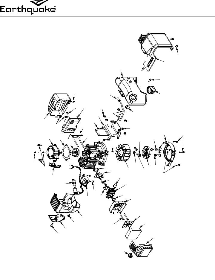
ILLUSTRATED PARTS BREAKDOWN - Engine Assembly
|
|
|
|
|
|
|
|
|
|
|
|
|
|
|
|
|
|
|
|
42 |
|
|
|
|
|
|
|
|
|
|
|
|
|
|
|
|
|
|
|
41 |
|
|
|
|
|
|
|
|
|
|
|
|
|
24 |
|
|
|
|
|
|
|
|
|
|
|
|
|
|
33,35 |
|
|
|
24,37,38 |
|
|
|
|
|
|
|
|
24,40 |
|
|
|
|
|
|
|
32,35 |
35 |
24 24,36 |
24,37 |
|
|
24,37 |
|
|
|
24,39 |
|
|||
|
35 |
27 |
34,35 |
28 |
29 |
|
31,35 30,35 25 |
|
|
44,45 |
|
|
43 |
48,49 |
|
49,51 |
52 |
13,45 |
||
13 |
25 |
|
|
|
|
|
|
|
14,16 |
14,15 |
9,11,53 |
45 |
45,46 |
47 |
49 |
49,50 |
|
|
||
26,27 |
23 |
|
|
|
|
|
13,14 |
8,9 |
|
25,45 |
|
|||||||||
|
|
|
|
|
|
|
22 |
17 |
9,12,14,53 |
|
|
|
9,10 |
2,7 |
2,5 |
|
|
|
|
|
|
|
|
|
21 |
20 |
19 |
18 |
|
|
|
2,6,9,14,53 |
|
|
|
|
2,4 |
1,2 |
|
|
|
|
|
|
|
|
|
|
|
|
|
|
|
3 |
|
|
|
|
|
|
|
|
16 |
Check for parts online at www.getearthquake.com or call 800-345-6007 M-F 8-5 |

Operator’s Manual
MC43 2-Cycle Cultivator
ILLUSTRATED PARTS BREAKDOWN - Engine Assembly
ITEM |
PART |
DESCRIPTION |
QTY. |
NO. |
NO. |
|
|
|
|
|
|
1 |
3004158 |
AIR FILTER COVER |
1 |
2 |
15230 |
KIT AIR FILTER ASSEMBLY |
1 |
|
|
|
|
3 |
1021 |
ROCKER SWITCH |
1 |
|
|
|
|
4 |
3004156 |
FOAM ELEMENT AIR FILTER |
1 |
|
|
BLOCK |
|
5 |
3004157 |
AIR FILTER REINFORCEMENT |
1 |
|
|
FRAME |
|
6 |
15209 |
BOLT M5 X 52 WITH WASHER |
2 |
7 |
3004150 |
AIR FILTER BASE ASSEMBLY |
1 |
|
|
|
|
8 |
15261 |
CARBURETOR 43CC NO TAMP |
1 |
|
|
|
|
9 |
11334 |
KIT CARBURETOR REPLACEMENT |
1 |
10 |
300481 |
CARBURETOR O-RING |
1 |
|
|
|
|
11 |
3004109 |
CARBURETOR PRIMER BULB |
1 |
|
|
|
|
12 |
300479 |
CARBURETOR GASKET |
1 |
13 |
17952 |
BOLT M5 X 28 WITH WASHER |
5 |
|
|
|
|
14 |
11205 |
KIT INTAKE MANIFOLD |
1 |
|
|
|
|
15 |
300478 |
WINDPIPE INTAKE |
1 |
16 |
300476 |
GASKET INTAKE |
1 |
|
|
|
|
17 |
300335 |
BOLT M5 X 20 HEX HEAD WITH |
2 |
|
|
WASHER |
|
18 |
300482 |
ENGINE SHROUD RED |
1 |
|
|
|
|
19 |
10887 |
BOLT M5 X 16 BUTTON HEAD |
1 |
|
|
WITH WASHER |
|
20 |
300483 |
ENGINE SHROUD CAP END |
1 |
|
|
BLACK |
|
21 |
300439 |
BOLT M5 X 20 BUTTON HEAD |
1 |
|
|
WITH WASHER |
|
22 |
26579 |
IGNITION COIL |
1 |
23 |
35906 |
SPARK PLUG L7RTC TORCH |
1 |
|
|
|
|
24 |
10683 |
KIT GAS TANK |
1 |
|
|
|
|
25 |
17946 |
BOLT M5 X 20 WITH WASHER |
7 |
26 |
3004121 |
RECOIL HANDLE |
1 |
|
|
|
|
ITEM |
PART |
DESCRIPTION |
QTY. |
NO. |
NO. |
|
|
|
|
|
|
27 |
300430 |
RECOIL ASSEMBLY |
1 |
|
|
|
|
28 |
300429 |
RECOIL SPACER PLATE |
1 |
|
|
|
|
29 |
300491 |
RECOIL CLUTCH CUP |
1 |
30 |
300493 |
STUD M6 X 62 |
2 |
|
|
|
|
31 |
300475 |
GASKET MUFFLER HEAT SHIELD |
1 |
|
|
|
|
32 |
300471 |
BOLT M5 X 12 WITH WASHER |
1 |
33 |
17888 |
BOLT M5 X 12 SOCKET HEAD |
1 |
|
|
WITH WASHER |
|
34 |
300492 |
NUT M6 X 1 HEX FLANGE |
2 |
|
|
|
|
35 |
25977 |
KIT MUFFLER STRAIGHT |
1 |
|
|
EJECTION DPS30 |
|
36 |
11190 |
SPACER M5 X 4 NYLON |
4 |
|
|
|
|
37 |
3004105 |
KIT FUEL LINE TWO HOLE |
1 |
|
|
GROMMET |
|
38 |
3004103 |
FUEL FILTER |
1 |
39 |
11936 |
GAS CAP TWO WAY SELF |
1 |
|
|
VENTING |
|
40 |
4647 |
BOLT M6 X 18 HEX FLANGE |
4 |
|
|
|
|
41 |
300332 |
GAS TANK SHROUD BLACK |
1 |
|
|
|
|
42 |
300336 |
BOLT M6 X 10 HEX FLANGE |
2 |
43 |
11189 |
SPACER M5 X 5 |
2 |
|
|
|
|
44 |
300338 |
KEY WOODRUFF 3 X 5 X 12 |
1 |
|
|
|
|
45 |
11209 |
KIT FLYWHEEL |
1 |
46 |
300337 |
NUT M8 X 1.25 HEX FLANGE |
1 |
|
|
|
|
47 |
300467 |
DOWEL PIN 5 X 12 |
2 |
|
|
|
|
48 |
300462 |
WASHER 15.8 X 8.4 X 1.6 |
2 |
49 |
11235 |
KIT CLUTCH |
1 |
|
|
|
|
50 |
300449 |
WAVE WASHER 10 X 15 X 0.25 |
2 |
|
|
|
|
51 |
300450 |
BOLT M8 X 25 SHOULDER 10 |
2 |
52 |
300487 |
FLYWHEEL SHROUD |
1 |
|
|
|
|
53 |
3004114 |
KIT CARBURETOR REPAIR |
1 |
|
|
|
|
Check for parts online at www.getearthquake.com or call 800-345-6007 M-F 8-5 |
17 |
Operator’s Manual
MC43 2-Cycle Cultivator
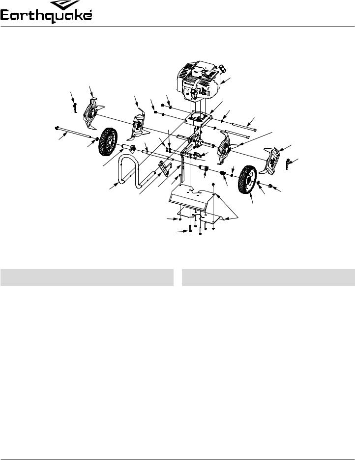
ILLUSTRATED PARTS BREAKDOWN - Hood & Tines Parts Explosion
|
|
2 |
|
|
|
|
30 |
|
|
|
1 |
|
|
|
|
|
|
|
|
|
|
3 |
4 |
5 |
|
|
|
|
|
|
|
|
|
6 (SEE DETAIL BREAKDOWN NEXT PAGE) |
|||||
|
|
|
|
|
|
||||
|
|
|
|
|
|
|
|||
|
|
|
|
|
|
|
5 |
7 |
|
|
|
|
|
|
|
|
|
|
|
|
|
|
|
|
19 |
|
|
|
8 |
|
|
|
|
18 |
|
|
|
|
|
10 |
|
|
16 |
|
|
|
|
9 |
|
|
11 |
|
|
|
|
|
|
||
|
|
|
|
|
17 |
|
|
1 |
|
|
|
|
|
|
|
29 |
28 |
|
|
|
|
13 |
|
|
|
|
|
||
|
|
|
|
|
|
|
|
|
|
|
|
|
|
|
22 |
26 |
|
|
|
|
|
14 |
20 |
21 |
|
27 |
|
15 |
|
|
|
|
|
|
|
11 |
|||
|
|
|
|
|
|
|
|
||
|
|
|
|
|
|
|
|
12 |
|
|
|
|
|
|
24 |
|
|
23 |
|
|
|
|
|
|
25 |
|
|
|
|
ITEM |
PART |
DESCRIPTION |
QTY. |
NO. |
NO. |
|
|
|
|
|
|
1 |
4652 |
HAIR PIN, 5/8-3/4 INCH COTTER |
2 |
2 |
4601 |
TINE “A” RIGHT OUTSIDE |
1 |
|
|
|
|
3 |
4603 |
TINE “B” RIGHT INSIDE |
1 |
|
|
|
|
4 |
400023 |
NUT M8 NYLOCK |
2 |
5 |
4641 |
WASHER M8 CURVED |
4 |
|
|
|
|
6 |
26013 |
TRANSMISSION ASSEMBLY |
1 |
|
|
|
|
7 |
46141 |
BOLT M8 X 1.25 X 155 HEX |
2 |
|
|
FLANGE |
|
8 |
4602 |
TINE “C” LEFT INSIDE |
1 |
9 |
4604 |
TINE “D” LEFT OUTSIDE |
1 |
|
|
|
|
10 |
4687 |
BOLT M10 X 1.5 X 231 HEX |
1 |
|
|
FLANGE |
|
11 |
2431 |
WASHER M10 NARROW FLAT |
2 |
|
|
|
|
12 |
13189 |
WHEEL 180 X 38 MM DIAMOND |
2 |
|
|
TREAD GREY HUB |
|
13 |
4678 |
GUIDE WHEEL TUBE |
1 |
14 |
15104 |
HANDLEBAR LOWER |
1 |
|
|
|
|
ITEM |
PART |
DESCRIPTION |
QTY. |
NO. |
NO. |
|
|
|
|
|
|
15 |
4629 |
NUT M10 X 1.5 CENTER LOCK HEX |
1 |
16 |
4674 |
WHEEL TUBE |
1 |
|
|
|
|
17 |
18039 |
PIN LOCK 8MM X 40MM |
1 |
|
|
|
|
18 |
4650 |
NUT M6 NYLOCK |
2 |
19 |
W1200117 |
WASHER M6 X 13 X 1.75 FLAT |
2 |
|
|
|
|
20 |
4673 |
WHEEL HOLDER |
1 |
|
|
|
|
21 |
4600 |
DRAG STAKE |
1 |
22 |
176 |
BOLT M5 X 0.8 X 10 HEX FLANGE |
2 |
|
|
|
|
23 |
23441 |
TINE SHIELD |
2 |
|
|
|
|
24 |
400020 |
NUT M5 X 0.8 NYLOCK FLANGE |
2 |
25 |
4625 |
BOLT M6 X 1.0 X 42 HEX FLANGE |
4 |
|
|
|
|
26 |
4684 |
TUBE WHEEL LOCK |
1 |
|
|
|
|
27 |
4685 |
SPRING WHEEL LOCK |
1 |
28 |
13230 |
WASHER 21 X 16 X 1 MM |
1 |
|
|
|
|
29 |
46142 |
BOLT M6 X 1.0 X 15 HEX FLANGE |
2 |
|
|
|
|
30 |
23433 |
ENGINE MC43 VIPER |
1 |
18 |
Check for parts online at www.getearthquake.com or call 800-345-6007 M-F 8-5 |

Operator’s Manual
MC43 2-Cycle Cultivator
ILLUSTRATED PARTS BREAKDOWN - Transmission Parts Explosion
|
|
|
|
|
|
21 |
|
|
|
|
|
|
|
|
|
|
|
20 |
|
|
|
|
|
|
|
|
|
|
|
19 |
|
|
|
|
|
1 |
|
|
|
|
|
14 |
|
|
|
|
|
|
|
|
|
17, 25 |
18, 25 |
|
|
|
|
|
|
|
|
|
|
|
|
16 |
|
|
|
|
|
|
|
|
|
|
|
15 |
|
|
|
|
|
|
|
|
10 |
11 |
12 |
|
|
|
|
|
|
|
|
|
|
|
|
|
|
|
|
|
|
2 |
|
|
|
|
|
11 10 |
|
|
|
|
|
3 |
|
|
7 |
|
|
|
|
|
|
|
|
4 |
5 |
6 |
|
9 |
13 |
|
|
|
23 |
||
|
|
|
|
|
|
|
|||||
|
|
|
|
|
|
|
|
|
|||
|
|
|
|
|
|
14 |
|
|
|
|
23 |
|
|
8 |
|
|
|
|
|
|
|
24 |
|
|
|
|
|
|
22 |
|
|
|
|
|
|
|
|
|
|
|
|
4 |
3 |
2 |
7 |
23 |
|
|
|
|
|
|
|
|
|
|
|||
|
|
|
|
|
|
|
|
|
|
||
ITEM |
PART NO. |
DESCRIPTION |
QTY. |
NO. |
|
|
|
1 |
26013 |
TRANSMISSION ASSEMBLY |
1 |
|
|
|
|
2 |
46144 |
DUST CAP |
2 |
|
|
|
|
3 |
4606 |
FIBER WASHER |
2 |
4 |
4646 |
TINE SHAFT SEAL |
2 |
|
|
|
|
5* |
--- |
TRANSMISSION CASTING LEFT |
1 |
|
|
|
|
6 |
4650 |
NUT M6 NYLOCK |
2 |
7 |
W1200117 |
WASHER M6 X 12 X 1 MM |
4 |
|
|
|
|
8 |
4633 |
WHEEL & DRAG STAKE MOUNT |
1 |
|
|
|
|
9 |
13600 |
BOLT M6 X 1.0 X 25 HEX FLANGE |
2 |
10 |
25159 |
TINE SHAFT BUSHING STEEL |
2 |
|
|
|
|
11 |
4610 |
TINE SHAFT SHIM |
2 |
|
|
|
|
12 |
4651 |
GEAR AND TINE SHAFT ASSY |
1 |
13 |
4616 |
BUSHING SPACER |
1 |
|
|
|
|
ITEM |
PART NO. |
DESCRIPTION |
QTY. |
NO. |
|
|
|
|
|
|
|
14 |
4614 |
DRIVE SHAFT BUSHING BRONZE |
2 |
|
|
|
|
15 |
21953 |
DRIVE SHAFT |
1 |
16 |
4617 |
THRUST BEARING REDUCER |
1 |
|
|
|
|
17 |
4618 |
THRUST WASHER |
2 |
|
|
|
|
18 |
4619 |
THRUST BEARING CAGE |
1 |
19 |
4623 |
BALL BEARING 9 X 26 X 8 MM |
1 |
|
|
|
|
20 |
300414 |
CLUTCH DRUM |
1 |
|
|
|
|
21 |
4620 |
JAM NUT M8 |
1 |
22* |
--- |
TRANSMISSION CASTING RIGHT |
1 |
|
|
|
|
23 |
4647 |
BOLT M6 X 1.0 X 18 HEX FLANGE |
6 |
|
|
|
|
24 |
13447 |
BOLT M6 X 1.0 X 8 PHILLIPS |
2 |
25 |
4615 |
KIT THRUST BEARING SET |
1 |
|
|
|
|
* PURCHASE TRANSMISSION ASSEMBLY 26013
Check for parts online at www.getearthquake.com or call 800-345-6007 M-F 8-5 |
19 |
Operator’s Manual
MC43 2-Cycle Cultivator
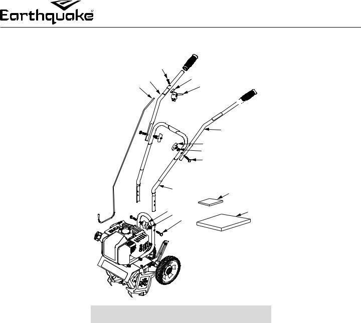
ILLUSTRATED PARTS BREAKDOWN - Handlebar Parts Explosion
|
1 |
2 |
4 |
3 |
5 |


 6
6
|
|
7 |
|
|
8 |
|
|
9 |
|
|
10 |
|
11 |
12 |
8 |
9 |
13 |
|
10 |
|
ITEM |
PART |
DESCRIPTION |
QTY. |
|
|
NO. |
NO. |
|
|
|
|
|
|
|
|
|
|
1 |
4814 |
BOLT 10-24 X 1-1/4 PHILLIPS |
1 |
|
|
2 |
23442 |
HANDLEBAR UPPER RIGHT |
1 |
|
|
|
|
|
|
|
|
3 |
14645 |
THROTTLE CABLE |
1 |
|
|
|
|
|
|
|
|
4 |
12633 |
RUBBER PAD |
1 |
|
|
5 |
4809 |
TRIGGER ASSEMBLY SHORT THROW |
1 |
|
|
|
|
|
|
|
|
6 |
4639 |
HANDLEBAR GRIP |
2 |
|
|
|
|
|
|
|
|
7 |
23443 |
HANDLEBAR UPPER LEFT |
1 |
|
|
8 |
4640 |
T-HANDLE NUT |
4 |
|
|
|
|
|
|
|
|
9 |
4641 |
CURVED WASHER |
4 |
|
|
|
|
|
|
|
|
10 |
4642 |
SADDLE BOLT |
4 |
|
|
11 |
4693 |
HANDLEBAR MIDDLE |
1 |
|
|
|
|
|
|
|
|
12 |
12621 |
HANDLEBAR PARTS PACKET |
1 |
|
|
|
|
|
|
|
|
13 |
23434 |
MANUAL PARTS BAG |
1 |
|
|
|
|
|
|
|
20 |
|
|
Check for parts online at www.getearthquake.com or call 800-345-6007 M-F 8-5 |
||
Operator’s Manual
MC43 2-Cycle Cultivator
15073 BORDER-EDGER KIT INSTALLATION (OPTIONAL ACCESSORY)
The Border-Edger Kit is a useful tool for making clean cuts in the lawn along the borders of gardens, flower beds, walkways, and driveways for a well manicured look. To install the BorderEdger Kit, do the following:
INSTALLATION
1.Make sure the cultivator is not running by turning the ON/ OFF switch to the OFF position.
2.Remove the hairpins from both sides of the tine shaft.
3.Remove the cultivating tines from the shaft.
4.Remove the drag stake and lock pin from the unit.
5.Store the tines and save the (2) hairpins; they will be used on the Border-Edger Kit.
6.Slide the border-edger tine onto either side of the tine shaft. Make sure that the hub collar of the border-edger tine faces outward, away from the transmission of the cultivator.
SEE FIGURE 10
7.Take the (2) hairpins saved in Step 4 and insert them through the inner and outer holes in the tine shaft on each side of the border-edger tine to secure the tine blade in place on the shaft. SEE FIGURE 10
8.Slide the border-edger wheel onto the opposite side of the tine shaft as far as it will go.
9.Insert the remaining (1) hairpin, that came with the kit, through the inner hole to secure the wheel. SEE FIGURE 10
10.Set the cultivator wheels to the HIGHEST (top) position.
SEE FIGURE 5 (PAGE 12)
BORDER-EDGER |
DRAG STAKE |
|
WHEEL |
||
REMOVED |
||
|
||
|
BORDER-EDGER |
|
|
TINE |
|
HAIR PIN |
TINE SHAFT |
|
|
||
FIGURE 10 |
HUB COLLAR |
|
|
PARTS BREAKDOWN
ITEM |
PART |
DESCRIPTION |
QTY. |
NO. |
NO. |
|
|
|
|
|
|
1 |
15009 |
BORDER-EDGER TINE |
1 |
2 |
46131 |
BORDER-EDGER WHEEL |
1 |
|
|
|
|
3 |
46134 |
HAIRPIN |
1 |
|
|
|
|
 CAUTION
BE AWARE THAT THE CULTIVATOR COULD
UNEXPECTEDLY BOUNCE UPWARD, OR JUMP
FORWARD IF THE TINE STRIKES CONCRETE,
PAVEMENT, OR OTHER HARD SURFACES OR HARD
OBSTACLES BURIED UNDER GROUND.
Check for parts online at www.getearthquake.com or call 800-345-6007 M-F 8-5 |
21 |
 Loading...