


STRATA 128
Strata 128Strata 128
Strata 128
Strata 128Strata 128
Strata 128 PlusStrata 128 Plus
Strata 128 Plus
Strata 128 PlusStrata 128 Plus
Strata 128 PorStrata 128 Por
Strata 128 Por
Strata 128 PorStrata 128 Por
INSTINST
INST
INSTINST
StrataVStrataV
StrataV
StrataVStrataV
ALLAALLA
ALLA
ALLAALLA
TION AND OPERATION AND OPERA
TION AND OPERA
TION AND OPERATION AND OPERA
INSTRINSTR
INSTR
INSTRINSTR
UCTIONSUCTIONS
UCTIONS
UCTIONSUCTIONS
1
iewiew
iew
iewiew
tabletable
table
tabletable
TIONTION
TION
TIONTION
®

TABLE OF CONTENTSTABLE OF CONTENTS
TABLE OF CONTENTS
TABLE OF CONTENTSTABLE OF CONTENTS
INTRODUCTION..............................................................................................3
SPECIFICATIONS ...........................................................................................3
INSTALLATION -Transducer ........................................................................... 5
POWER CONNECTIONS ...............................................................................13
BRACKET INSTALLATION ............................................................................14
PORTABLE ASSEMBLY ................................................................................15
SPEED/TEMP SENSORS ..............................................................................16
KEYBOARD BASICS ......................................................................................20
DISPLAY .........................................................................................................2 0
OPERATION ................................................................................................... 2 1
MENUS ...........................................................................................................21
AUTOMATIC ................................................................................................... 2 1
RANGE ...........................................................................................................2 1
ZOOM .............................................................................................................2 2
SENSITIVITY ..................................................................................................24
GRAYLINE® ...................................................................................................24
FISH ID ...........................................................................................................25
FISH TRACK™ ...............................................................................................26
TARGET TRACK ............................................................................................26
CHART SPEED ..............................................................................................27
DISPLAY MODE .............................................................................................28
ALARMS .........................................................................................................3 2
BACK LIGHT...................................................................................................33
FEET/METER .................................................................................................33
DISPLAY CONTRAST ....................................................................................33
ASP (Advanced Signal Processing) ...............................................................34
SIMULATOR ...................................................................................................34
TROUBLESHOOTING .................................................................................... 35
WARRANTY ...................................................................................................38
Copyright © 1998, Eagle ElectronicsCopyright © 1998, Eagle Electronics
Copyright © 1998, Eagle Electronics
Copyright © 1998, Eagle ElectronicsCopyright © 1998, Eagle Electronics
All features and specifications in this manual are subject to change
without notice.
All screens in this manual are simulated.
Eagle Electronics
PO Box 669
Catoosa, OK 74015
2
INTRODUCTION
Thank you for purchasing an Eagle sonar. Your sonar unit is a high quality
sonar designed for both professional and novice fishermen. All of our
sonars have an automatic feature that finds and displays the bottom, fish,
structure, and more! All you have to do is press the on key. However, if
you wish to fine tune the unit, all you have to do is press the menu key. The
Strata series has powerful features available through easy-to-use menus.
To get started with your Eagle unit, first read the installation section. This
is where it all begins. Improper installation can cause problems down the
road. After you’ve read the instructions, install the unit, then read the rest
of the manual. The more you know about your unit, the better it will perform
for you. Take this manual for reference when you head for the water.
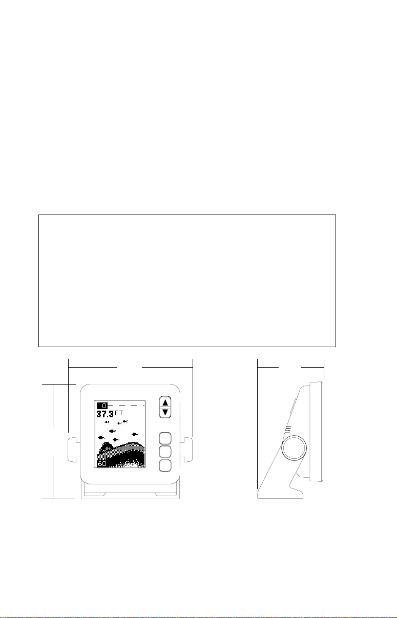
SPECIFICATIONS
Dimensions ...................... 5.9" W x 5.35" H x 3.4" D
Input Voltage .................... 10 - 15 vDC
Current Drain ................... 350 ma (lights off)
........................... 500 ma (lights on)
Transmitter
Frequency.......... 192 kHz
Output Power..... 275 watts (peak-to-peak) (typical)
........................... 34.4 watts (RMS)
Display ........................... 128 pixels (H) x 65 pixels (W)
........................... Supertwist Liquid Crystal Display
5.9" 3.4"
5.35"
NOTICE!
The storage temperature for your unit is from -4 degrees to +167 degrees
Fahrenheit (-20 degrees to +75 degrees Celcius). Extended storage in temperatures higher or lower than specified will damage the liquid crystal display in your
unit. This type of damage is not covered by the warranty. For more information,
contact the factory customer service department or your local service center.
3

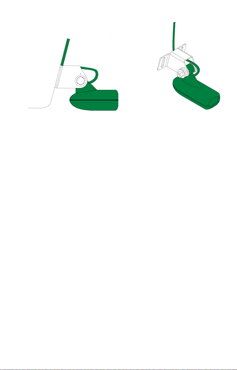
Transducer Installation
The transducer included with your sonar is a transom mount transducer
The “kick-up” mounting bracket helps prevent damage if the transducer
strikes an object while the boat is moving. If the transducer does “kickup”, the bracket can easily be pushed back in place without tools.
Read this manual carefully before attempting the installation. Determine
which of the mounting positions is right for your boat. Use extreme care
if mounting the transducer inside the hull, since once it is epoxied into
position, the transducer usually cannot be removed. Remember, the
transducer location is the most critical part of a sonar installation.
Location - General
1. The transducer must be placed in a location that has a smooth flow of
water at all times. If the transducer is to be mounted inside the hull,
then the chosen location must be in the water at all times. If the
transducer is not placed in a smooth flow of water, interference will
show on the sonar’s display in the form of random lines or dots
whenever the boat is moving.
2. The transducer should be installed with it’s face pointing straight
down, if possible.
3. If the transducer is mounted on the transom, make certain it doesn’t
interfere with the trailer or hauling of the boat. Also, don’t mount it
closer than approximately one foot from the engine’s lower unit. This
will prevent cavitation interference with the propeller. Typically, the
transducer should be mounted as deep in the water as possible. This
increases the chance that it will be in the water in high speed and
reduces the possiblity of air bubble interference.
4. If possible, route the transducer cable away from other wiring on the
boat. Electrical noise from engine wiring, bilge pumps, and areators
can be displayed on the sonar’s screen. Use caution when routing
the transducer cable around these wires.
4

Shoot-thru-hull v.s. Transom Mounting
(Strata 128 and Strata 128 Plus Only)
Typically, shoot-thru-hull installations give excellent high speed operation and good to excellent depth capability. There is no possibility of
damage from floating objects. It can't be knocked off when docking or
loading on the trailer.
However, the shoot-thru-hull installation does have its drawbacks. One,
some loss of sensitivity does occur, even on the best hulls. This varies
from hull to hull, even from different installations on the same hull. This
is caused by differences in hull layup and construction. Two, the angle
of the transducer cannot be adjusted for the best fish arches. This can
be a problem on some hulls that sit with the bow high when at rest or at
slow trolling speeds. Follow the procedure listed in the shoot-thru-hull
installation section in this manual to determine if you can satisfactorily
shoot through the hull.
T ransducer Assemb l y and Mounting - All Units
The best way to install this transducer is to loosely assemble all of the
parts first, place the transducer’s bracket against the tr ansom and see if
you can move the tr ansducer so that it’s parallel with the ground.
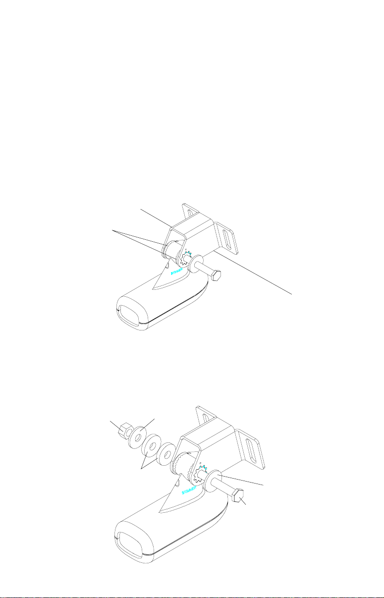
1. Press the two small plastic ratchets into the sides of the metal brac ket
as shown below. Notice there are letters molded into each ratchet.
Place each ratchet into the bracket with the letter “A” aligned with the
dot stamped into the metal bracket. This position sets the transducer’ s
coarse angle adjustment for a fourteen (14) degree transom. Most
outboard and stern-drive transoms have a fourteen degree angle.
DOT
5
2. Slide the transducer between the two ratchets. Temporally slide the
bolt though the transducer assembly and hold it against the transom.
Looking at the transducer from the side, check to see if it will adjust so
that its face is parallel to the ground. If it does, then the “A” position is
correct for your hull. If the transducer’ s face isn’t parallel with the ground,
remove the transducer and r atchets from the bracket. Place the ratchets into the holes in the bracket with the letter “B” aligned with the dot
stamped in the bracket. Reassemble the transducer and brac ket and
place them against the transom. Again, chec k to see if y ou can mo ve
the transducer so it’s parallel with the ground. If you can, then go to
step 3. If it doesn’t, repeat step 2, b ut use a different letter until you can
place the transducer on the transom correctly.
RATCHETS
3. Once you determine the correct position for the ratchets, assemble
the transducer as shown at left. Don't tighten the loc k nut at this time.
METAL
NUT
WASHER
RUBBER
WASHERS
METAL
WASHER
BOLT
6
CAUTION!CAUTION!
CAUTION!
CLAMP THE TRANSDUCER CABLE TOCLAMP THE TRANSDUCER CABLE TO
CLAMP THE TRANSDUCER CABLE TO
CLAMP THE TRANSDUCER CABLE TOCLAMP THE TRANSDUCER CABLE TO
TRANSOM NEAR THE TRANSDUCER. THISTRANSOM NEAR THE TRANSDUCER. THIS
TRANSOM NEAR THE TRANSDUCER. THIS
TRANSOM NEAR THE TRANSDUCER. THISTRANSOM NEAR THE TRANSDUCER. THIS
WILL HELP PREVENT THE TRANSDUCERWILL HELP PREVENT THE TRANSDUCER
WILL HELP PREVENT THE TRANSDUCER
WILL HELP PREVENT THE TRANSDUCERWILL HELP PREVENT THE TRANSDUCER
FROM ENTERING THE BOAT IF IT ISFROM ENTERING THE BOAT IF IT IS
FROM ENTERING THE BOAT IF IT IS
FROM ENTERING THE BOAT IF IT ISFROM ENTERING THE BOAT IF IT IS
KNOCKED OFF AT HIGH SPEED.KNOCKED OFF AT HIGH SPEED.
KNOCKED OFF AT HIGH SPEED.
KNOCKED OFF AT HIGH SPEED.KNOCKED OFF AT HIGH SPEED.
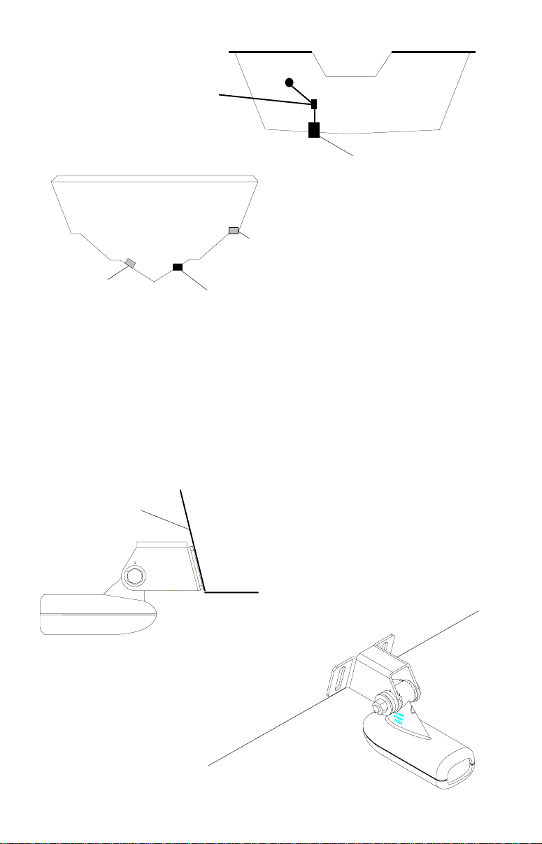
POOR ANGLEPOOR ANGLE
POOR ANGLE
POOR ANGLEPOOR ANGLE
CAUTION!CAUTION!
POOR LOCATIONPOOR LOCATION
POOR LOCATION
POOR LOCATIONPOOR LOCATION
GOOD LOCATIONGOOD LOCATION
GOOD LOCATION
GOOD LOCATIONGOOD LOCATION
GOOD LOCATIONGOOD LOCATION
GOOD LOCATION
GOOD LOCATIONGOOD LOCATION
4. Hold the transducer and bracket assembly against the transom. The
transducer should be roughly parallel to the ground. The bottom of the
transducer bracket should be in line with the bottom of the hull.
let the bracket extend below the hull!
Mark the center of the slots for
Don't
the mounting holes. Drill two 5/32" holes in the marked locations for
the #10 screws supplied with the transducer .
TRANSOM
SIDE VIEW
7
5. Remove the transducer from the bracket and re-assemble it with the
cable passing through the bracket over the bolt as shown above. Attach the transducer to the transom. Slide the transducer up or down
until it’s aligned properly on the transom as shown abov e. Tighten the
bracket’ s mounting screws. Adjust the transducer so that it’ s parallel to
the ground and tighten the lock nut until it touches the flat washer , then
add 1/4 turn.
Don’t over tighten the lock n ut!
If you do, the tr ansducer
won’t “kic k-up” if it strikes an object in the water .
6. Route the transducer cable to the sonar unit. Make certain to leave
some slack inthe cable at the transducer as shown abo ve . If possib le,
route the transducer cable aw ay from other wiring on the boat. Electrical noise from the engine’s wiring, bilge pumps, VHF radio wires and
cables, and aerators can be pic ked up by the sonar . Use caution when
routing the transducer cable around these wires.
IMPORTANT!
Clamp the transducer cable to the transom close to the transducer. This
can prevent the transducer from entering the boat if it is knocked off at
high speed.
7. Make a test run to determine the results. If the bottom is lost at high
speed, or if noise appears on the display, try sliding the transducer
bracket down. This puts the transducer deeper into the water, hopefully below the turbulence causing the noise. Don't allow the transducer bracket to go belo w the bottom of the hull!
8
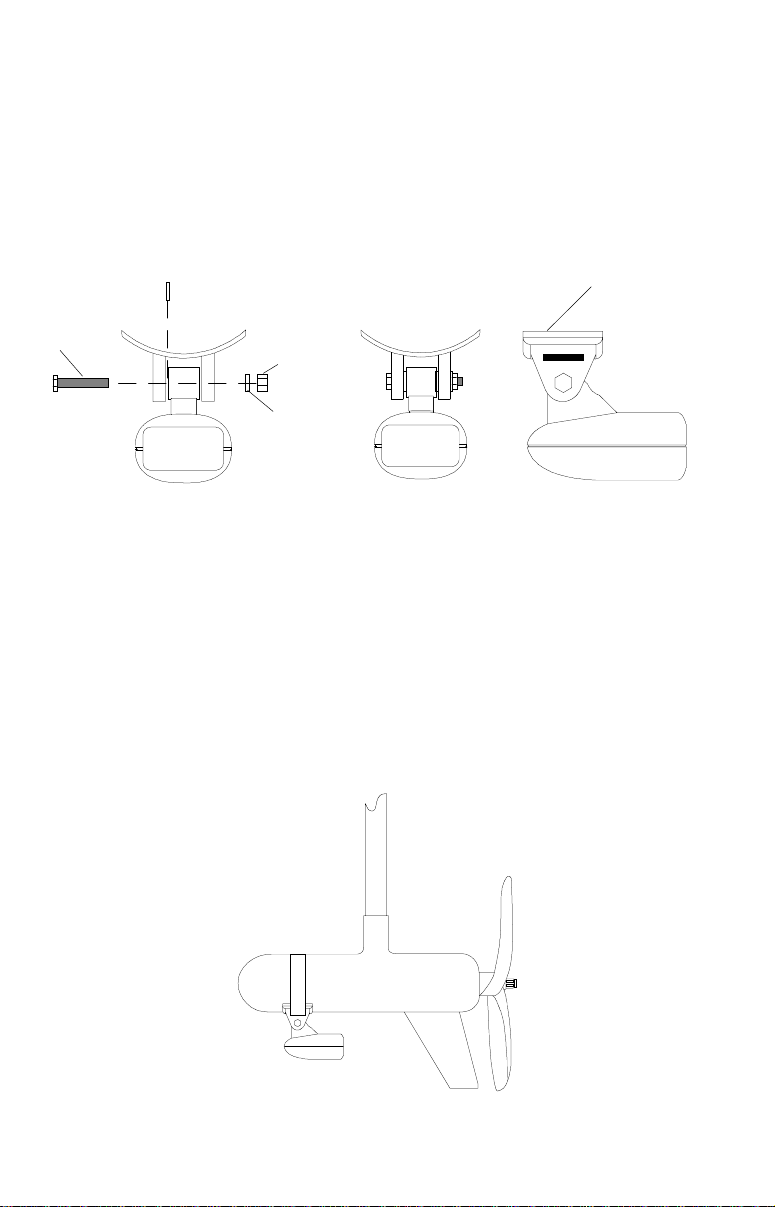
TROLLING MOTOR BRACKET INSTALLATION
(StrataView Only)
1. Attach the TMB-S bracket to the transducer as shown below using the
hardware supplied with the transducer. (Note: The internal tooth washer
is supplied with the TMB-S.)
INTERNAL TOOTH
WASHER
BOLT
NUT
FLAT WASHER
TMB-S
BRACKET
2. Slide the adjustable strap supplied with the TMB-S through the slot in
the transducer bracket and wrap it around the trolling motor. Position
the transducer to aim straight down when the motor is in the water.
Tighten the strap securely. Route the transducer cable alongside the
trolling motor shaft. Use plastic ties (not included) to attach the
transducer cable to the trolling motor shaft. Make certain there is
enough slack in the cable for the motor to turn freely. Route the cable
to the sonar unit and the transducer is ready for use.
9
SHOOT-THRU-HULL
(Strata 128 and Strata 128 Plus Only)
The transducer installation inside a fiberglass hull must be in an area
that does not have air bubbles in the resin or separated fiberglass
layers. The sonar signal must pass through solid fiberglass. A successful transducer installation can be made on hulls with flotation materials
(such as plywood, balsa wood, or foam) between layers of fiberglass if
the material is removed from the chosen area. For example, some
manufacturers use a layer of fiberglass, then a core of balsa wood,
finishing with an outer layer of fiberglass. Removing the inner layer of
fiberglass and the balsa wood core exposes the outer layer of fiberglass.
The transducer can then be epoxied directly to the outer layer of fiberglass. After the epoxy cures, the hull is watertight and structurally sound.
Remember, the sonar signal must pass through solid fiberglass. Any air
bubbles in the fiberglass or the epoxy will reduce or eliminate the sonar
signals.
To choose the proper location for thru-hull mounting, anchor the boat in
60 feet of water. Add a little water to the sump of the boat. Plug the
FILL WITH EPOXY
INNER HULL
EPOXY TO HULL FIRST
OUTER HULL
transducer into the sonar unit, turn it on, then hold the transducer over
the side of the boat. Adjust the sensitivity and range controls until a
second bottom echo is seen on the display. (you will need to turn both
automatic and ASP off.) Don’t touch the controls once they’ve been set.
Next, take the transducer out of the water and place it in the water in the
sump of the boat. Observe the sonar signal to see if there is a noticeable decrease in sensitivity. The second bottom signal may disappear
and the bottom signal may decrease in intensity. Move the transducer
around to find the best location. If the sensitivity control has to be
increased greatly to compensate, then the transducer should be
mounted on the outside of the hull. If not, then mark the location that
shot through the hull the best and follow the instructions on the next
pages for a shoot-thru-hull mounting.
10
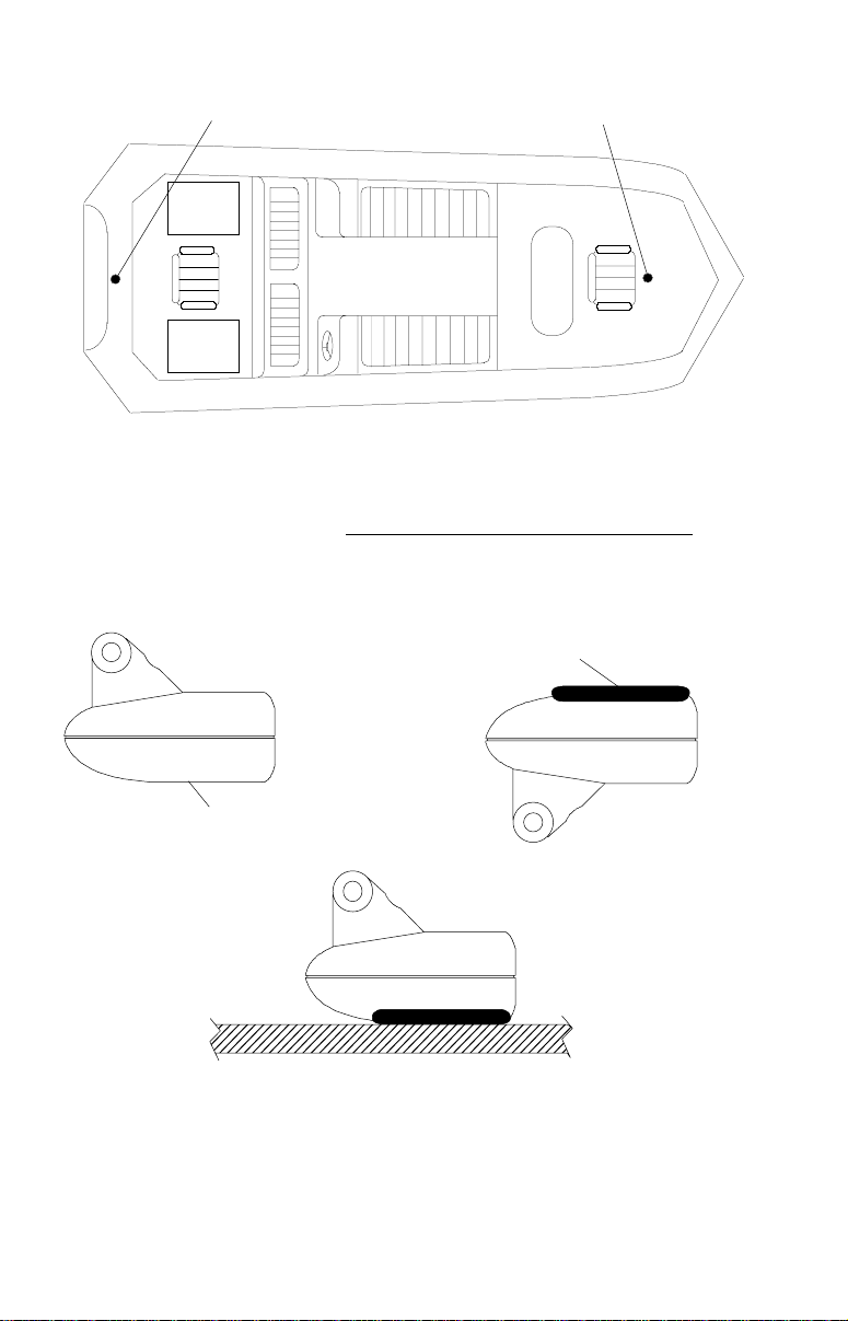
TRANSDUCER LOCATION
(HIGH SPEED)
TRANSDUCER LOCATION
(TROLLING SPEED)
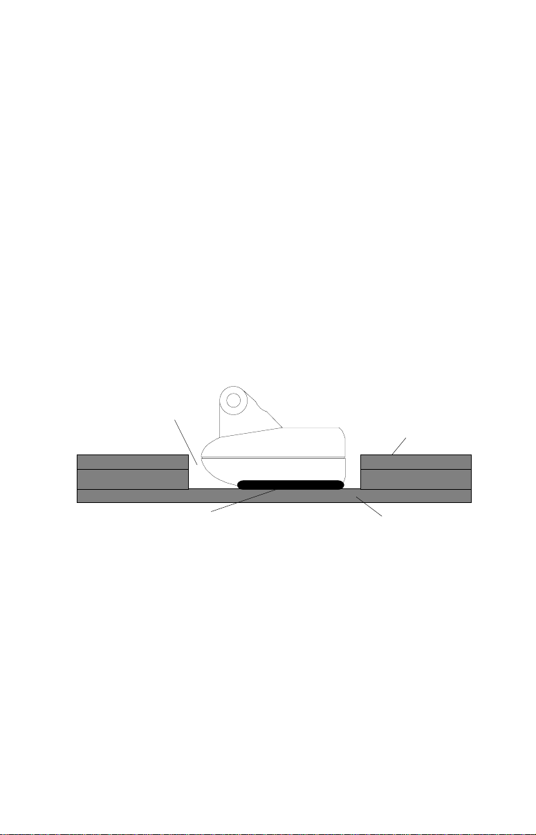
Shoot-thru-hull Installation
(Strata 128 and Strata 128 Plus Only)
1. Make certain the area is clean, dry, and free of oil or grease, then
sand both the inside surface of the hull and the face of the transducer
with 100 grit sandpaper. The surface of the hull must be flat so the entire
transducer face is in contact with the hull prior to bonding.
SPREAD EPOXY HERE
SAND THIS SURFACE
2. Follow the instructions on the epoxy package and mix it thoroughly.
Do not mix it too fast, as it will cause bubbles to form in the epoxy.
(NOTE! Use only the epoxies specified on the inside front cover of this
manual! Failure to use one of these epoxies may result in poor sonar
performance!) Apply a small amount on the face of the transducer as
shown above, then spread a small amount onto the sanded area on the
11
hull. Place the transducer into the epoxy, twisting and turning it to force
any air bubbles out from under the transducer face. The face of the
transducer should be parallel with the hull, with a minimum amount of
epoxy between the hull and transducer. After the epoxy dries, route the
cable to the sonar unit.
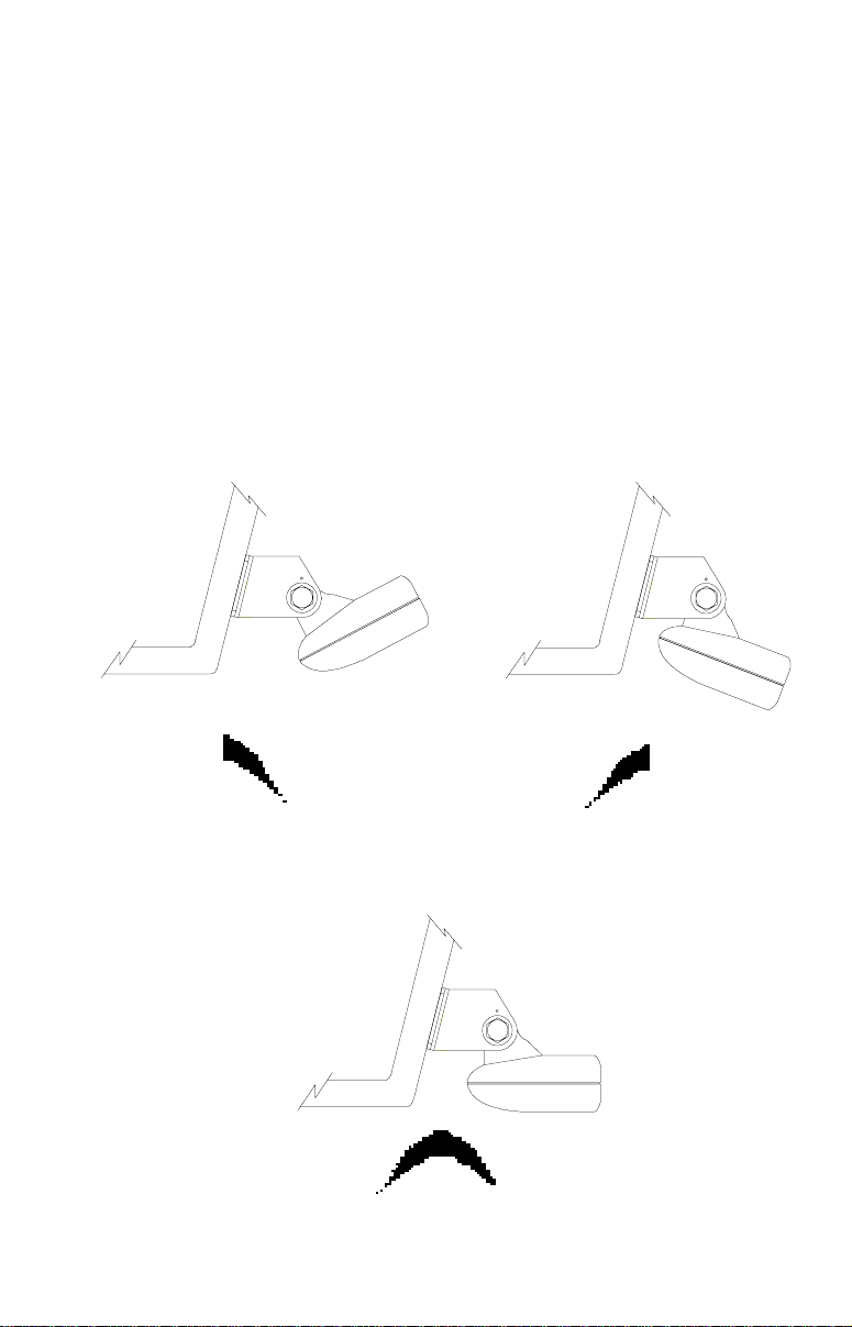
Fish Arches
If you do not get good fish arches on your display, it could be the
transducer is not parallel with the ground when the boat is at rest in the
water, or at slow trolling speeds. If the arch slopes up, but not back
down, then the front of the transducer is too high and needs to be
lowered. If only the back half the the arch is printed, then the nose of the
transducer is angled too far down and needs to be raised.
TRANSDUCER AIMED TOO FARTRANSDUCER AIMED TOO FAR
TRANSDUCER AIMED TOO FAR
TRANSDUCER AIMED TOO FARTRANSDUCER AIMED TOO FAR
BACKBACK
BACK
BACKBACK
PROPER TRANSDUCER ANGLEPROPER TRANSDUCER ANGLE
PROPER TRANSDUCER ANGLE
PROPER TRANSDUCER ANGLEPROPER TRANSDUCER ANGLE
12
TRANSDUCER AIMED TOOTRANSDUCER AIMED TOO
TRANSDUCER AIMED TOO
TRANSDUCER AIMED TOOTRANSDUCER AIMED TOO
FAR FORWARDFAR FORWARD
FAR FORWARD
FAR FORWARDFAR FORWARD
 Loading...