


FISHMARK 640C
www.eaglesonar.com
Pub. 988-0143-861
Fish-Finding & Depth-Sounding Sonars
Installation and Operation
Instructions

Copyright © 2005 LEI-Eagle
All rights reserved.
®
Eagle
, FishMark® and SeaFinder® are registered trademarks of LEI
No part of this manual may be copied, reproduced, republished,
transmitted or distributed for any purpose, without prior written
consent of Eagle Electronics. Any unauthorized commercial
distribution of this manual is strictly prohibited.
Eagle Electronics may find it necessary to change or end our policies,
regulations, and special offers at any time. We reserve the right to do so
without notice. All features and specifications subject to change without
notice. All screens in this manual are simulated. On the cover:
SeaFinder
®
640c DF shown. Other models covered in the manual are
similar.
For free owner's manuals and the most current information on
this product, its operation and accessories,
visit our web site:
www.eaglesonar.com
Eagle Electronics
P.O. Box 669
Catoosa, OK USA 74015
Printed in USA.

Table of Contents
Read Me First!...................................................................................1
Capabilities and Specifications: FishMark
SeaFinder
®
640c DF.............................................................................2
How Sonar Works ................................................................................4
How to Use this Manual: Typographical Conventions.......................5
Arrow Keys.......................................................................................5
Keyboard ..........................................................................................5
Menu Commands .............................................................................5
Instructions = Menu Sequences ......................................................5
Section 2: Installation & Accessories...........................................7
Preparations.........................................................................................7
Transducer Installation.......................................................................7
Recommended Tools and Supplies ..................................................8
Selecting a Transducer Location.....................................................9
How low should you go?.................................................................10
Shoot-Thru-Hull vs. Transom Mounting ......................................11
Transom Transducer Assembly and Mounting ............................12
Trolling Motor Bracket Installation (single-frequency only) .......19
Transducer Orientation and Fish Arches .....................................20
Shoot-Thru-Hull Preparation........................................................21
Testing Determines Best Location................................................22
Shoot-Thru-Hull Installation ........................................................24
Speed/Temperature Sensors..............................................................26
Optional Speed Sensor Installation ..................................................27
Power Connections.............................................................................29
Mounting the Unit: Bracket, In-Dash or Portable .......................31
Bracket Installation.......................................................................32
In-Dash Installation ......................................................................34
Portable Installation......................................................................34
Basic Sonar Operation ..................................................................37
Keyboard ............................................................................................37
Power/lights on and off ......................................................................38
®
640c ..............................2
i

Main Menu .........................................................................................39
Pages ..................................................................................................40
Basic Sonar Quick Reference ......................................................45
Sonar Operations ...............................................................................46
Fish Symbols vs. Full Sonar Chart ...............................................50
Other Free Training Aids ..............................................................50
Section 4: Sonar Options & Other Features.............................52
ASP (Advanced Signal Processing)................................................53
To change the ASP level ................................................................54
Alarms ................................................................................................54
Depth Alarms .................................................................................55
Zone Alarm .....................................................................................56
Fish Alarm......................................................................................57
Backlight and Contrast Level ...........................................................58
Calibrate Speed..................................................................................59
Chart Speed........................................................................................60
ColorLine.........................................................................................61
Depth Cursor......................................................................................62
Depth Range - Automatic ..................................................................63
Depth Range - Manual ......................................................................64
FasTrack .........................................................................................65
Fish I.D. (Fish Symbols & Depths) ................................................65
To turn the Fish I.D. feature on ....................................................67
FishTrack ........................................................................................67
To turn on FishTrack.....................................................................67
Frequency (Change Transducer Frequency) (SeaFinder only)........68
To change the frequency setting to 50 kHz ..................................69
To change the frequency setting to 200 kHz ................................69
HyperScroll .....................................................................................69
Noise Rejection...................................................................................69
Overlay Data ......................................................................................69
Ping Speed & HyperScroll..............................................................72
To change Ping Speed ....................................................................73
To adjust Sensitivity......................................................................73
ii

To turn off HyperScroll..................................................................74
Pop-up Help........................................................................................74
Reset Options .....................................................................................75
Reset Water Distance ........................................................................76
Set Keel Offset ...................................................................................76
Sensitivity & Auto Sensitivity...........................................................78
Automatic Sensitivity ....................................................................78
To turn Auto Sensitivity back on ..................................................79
Set Language .....................................................................................80
Software Version Information...........................................................80
Sonar Chart Mode..............................................................................80
To change the chart mode color scheme .......................................81
Sonar Page & Sonar Chart Display Options ....................................81
Full Sonar Chart ............................................................................81
Split Zoom Sonar Chart.................................................................82
Digital Data/Chart .........................................................................83
Sonar Simulator.................................................................................85
Stop Chart ..........................................................................................86
Surface Clarity...................................................................................87
To adjust the Surface Clarity level ...............................................87
Transparency .....................................................................................88
To adjust Menu Transparency level..............................................89
Units of Measure................................................................................89
Zoom & Zoom Bar ..............................................................................90
Zoom Pan............................................................................................91
Section 5: Troubleshooting ..........................................................92
Unit won't turn on..........................................................................93
Unit operates only in demo mode..................................................93
Unit freezes, locks up, or operates erratically ..............................93
Weak bottom echo, digital readings erratic, or no fish signals....94
No fish arches when the Fish I.D. feature is off:.........................95
Noise ...............................................................................................95
Section 6: Supplemental Material ..............................................97
iii

Notes
iv

Section 1: Read Me First!
How this manual can get you out on the water, fast!
Welcome to the exciting world of digital sonar! We know you're anxious
to begin finding fish, but we have a favor to ask. Before you grab your
unit and begin installing it, please give us a moment or two to explain
how our manual can help you get the best performance from your compact, wide-screen, fish finder.
First, we want to thank you for buying an Eagle sonar. Whether you're
a first time user or a professional fisherman, you'll discover that your
unit is easy to use, yet capable of handling demanding sonar tasks. You
won't find another sonar unit with this much power and this many features for this price!
Our goal for this book is to get you on the water fast, with a minimum
of fuss. Like you, we'd rather spend more time boating or fishing and
less time reading the manual!
So, we designed our book so that you don't have to read the whole thing
from front to back for the information you want. At the start (or end) of
each segment, we'll tell you what content is coming up next. If it's a
concept you're already familiar with, we'll show you how and where to
skip ahead for the next important topic. We've also made it easy to look
up any tips you may need from time to time. Here's how:
The manual is organized into 6 sections. This first section is an introduction to the sonar unit. It tells you the basics you need to know before
you can make the unit look below the surface to find some fish.
Section 2 will help you install your unit and the transducer. We'll also
tell you about some of the available accessories.
Section 3 covers Basic Sonar Operation. It will show you how easy it is
to run your sonar, right out of the box. This section features a one-page
Sonar Quick Reference. (If you've already jumped ahead and fig-
ured out how to install the unit yourself, and you just can't wait
1

any longer, turn to the Quick Reference on page 45 and head
for the water with your sonar unit!)
After you have gained some experience with your sonar, you'll want to
check out Section 4, which explains more advanced Sonar Options and
Other Features.
When you come to a sonar menu command you can look it up in the manual by skimming over the table of contents, just flipping through Section 3
or scanning through the sonar options in Section 4.
If you're having difficulty with your sonar, you can find an answer to
the most common problems in Section 5, Sonar Troubleshooting.
Finally, in Section 6, we offer Supplemental Material, including a list of
warranty and customer service information.
Now, if you're into the fine details, glance over the next segment on specifications to see just how much sonar power your unit contains. It's important to us (and our power users), but, if you don't care how many watts of
power the unit has, skip ahead to important information on how sonar
works, on page 4.
Capabilities and Specifications: FishMark® 640c,
SeaFinder® 640c DF
General
Display:............................ 5.0" (12.7 cm) diagonal 256-color TFT LCD;
programmable to viewing preference.
Resolution:...................... 640V x 480H pixel resolution; 307,200 total
pixels
Backlighting:.................. Backlit screen and keypad with multiple
lighting levels for night use.
Input power:................... 10 to 15 volts DC.
Case size:......................... 5.4" H x 6.9" W x 3.4" D (13.8 x 17.6 x 8.6
cm); sealed and waterproof; suitable for
saltwater use.
2

Back-up memory: .......... Built-in memory stores sonar settings for
decades.
Languages:...................... 10; menu languages selectable by user.
Sonar
Frequency:...................... 50/200 kHz for SeaFinder 640c DF; 200
kHz for FishMark 640c.
Transducers: .................. A dual-frequency Skimmer
transducer with
built-in temperature sensor is packed with
the SeaFinder 640c DF. It has 35°/12° cone
angles. A single-frequency Skimmer transducer with built-in temperature sensor is
packed with the FishMark 640c. It has a
20° cone angle. Transducers operate at
speeds up to 70 mph (61 kts)
Watts: ............................... SeaFinder 640c DF: 4,000 watts peak-to-
peak/500 watts RMS. FishMark 640c: 1,500
watts peak-to-peak/100 watts RMS.
Sonar sounding
Depth capability:........... SeaFinder 640c DF: 1,500 feet (457 me-
ters). FishMark 640c: 800 feet (244 meters).
Actual capability depends on transducer configuration and installation, bottom composition and water conditions. All sonar units
typically read deeper in fresh water than in
salt water.
Depth display:................ Continuous display .
Audible alarms: ............. Deep/shallow/fish/zone.
Automatic ranging:....... Yes, with instant screen updates.
Auto bottom track:........ Yes.
Zoom bottom track: ...... Yes.
Split-screen zoom:......... Yes.
3

Surface water temp: ..... Yes.
Speed/distance log: ....... Optional (requires optional speed sensor).
NOTICE!
The storage temperature range for your unit is from -4 degrees to
+167 degrees Fahrenheit (-20 degrees to +75 degrees Celsius). Ex-
tended storage in temperatures higher or lower than specified will
damage the liquid crystal display in your unit. This type of damage
is not covered by the warranty. For more information contact the
factory's Customer Service Department. The phone numbers are
listed on the last page.
How Sonar Works
Sonar has been around since the 1940s, so if you already know how it
works, skip ahead to the next segment on the typographical conventions
used in this manual. But, if you have never owned a sonar fish finder,
this segment will explain the under water basics.
Sonar is an abbreviation for SOund NA
nology developed during World War II for tracking enemy submarines.
A sonar consists of a transmitter, transducer, receiver and display. In
simple terms, here's how it finds the bottom and the fish:
The transmitter emits an electrical impulse which the transducer converts into a sound wave and sends into the water. The sound frequency
can't be heard by humans or fish. The sound wave strikes an object
(fish, structure, bottom) and bounces back to the transducer which converts the sound back into an electrical signal.
The receiver amplifies this return signal, or echo, and sends it to the
display where an image of the object appears on the scrolling sonar
chart. The sonar's microprocessor calculates the time lapse between the
transmitted signal and echo return to determine the distance to the
object. The whole process repeats itself several times each second.
vigation and Ranging, a tech-
4

How to Use this Manual: Typographical Conventions
Many instructions are listed as numbered steps. The keypad and arrow
"keystrokes" appear as boldface type. So, if you're in a real hurry (or
just need a reminder), you can skim the instructions and pick out what
menu command to use by finding the boldface command text. The following paragraphs explain how to interpret the text formatting for
those commands and other instructions:
Arrow Keys
The arrow keys control a horizontal line depth cursor on the sonar
screen. The arrow keys also help you move around the menus so you
can execute different commands. They are represented by symbols like
these, which denote the down arrow key, the up arrow, the left arrow
and the right arrow: ↓ ↑ ← →.
Keyboard
The other keys perform a variety of functions. When the text refers to a
key to press, the key is shown in bold, sans serif type. For example, the
"Enter/Icons" key is shown as
Menu Commands
A menu command or a menu option will appear in small capital letters,
in a bold sans serif type like this:
are to select this command or option from a menu or take an action of
some kind with the menu item. Text that you may need to enter or file
names you need to select are show in italic type, such as data type.
Instructions = Menu Sequences
Most functions you perform with the sonar unit are described as a sequence of key strokes and selecting menu commands. We've written
them in a condensed manner for quick and easy reading.
ENT and the "Menu" key is shown as MENU.
DEPTH CURSOR. These indicate that you
5

For example, instructions for turning on the Fish ID feature would
look like this:
1. From the Sonar Page, press
2. Press → or → ↓ to
FISH ID SYMBOLS|ENT|EXIT|EXIT.
MENU|↓ to SONAR FEATURES|ENT.
Translated into complete English, step 1 above would mean: "Start on
the Sonar Page. Press the Menu key then repeatedly press (or press and
hold) the down arrow key to scroll down the menu and select (highlight)
the Sonar Features menu command. Then press the Enter key."
Step 2 would mean: "Press the right arrow key (for dual-frequency
units) or press the right arrow key followed by the down arrow key (for
single-frequency units) to select (highlight) the Fish ID symbols command. Next, press the Enter key, then press the Exit key twice."
6

Section 2: Installation & Accessories
Preparations
You can install the sonar system in some other order if you prefer, but
we recommend this installation sequence:
Caution:
You should read over this entire installation section before drilling any holes in your vessel!
1. Determine the approximate location for the sonar unit, so you can
plan how and where to route the cables for the transducer and power.
This will help you make sure you have enough cable length for the desired configuration.
2. Determine the approximate location for the transducer and its cable
route.
3. Determine the location of your battery or other power connection,
along with the power cable route.
4. Install the transducer and route the transducer cable to the sonar
unit.
5. Route the power cable from the unit's location to an appropriate
power source and connect it there.
6. Connect the transducer/power cable to the unit and mount the sonar
unit on the bracket.
Transducer Installation
These instructions will help you install your Skimmer
transom, on a trolling motor or inside a hull. These instructions cover
both single- and dual-frequency Skimmer transducers. Please read all
instructions before proceeding with any installation.
Your Skimmer transducer typically comes packaged with a one-piece
stainless steel bracket for mounting it to the transom of your boat. The
optional trolling motor mount uses a one-piece plastic bracket with an
7
transducer on a

adjustable strap. These are "kick-up" mounting brackets. They help
prevent damage if the transducer strikes an object while the boat is
moving. If the transducer does "kick-up" the bracket can easily be
pushed back into place without tools.
Read these instructions carefully before attempting the installation.
Determine which of the installation methods is right for your boat.
Remember, the transducer location and installation is the most
critical part of a sonar installation.
Recommended Tools and Supplies
If you prefer the option of routing the cable through the transom, you
will need a 5/8" drill bit. If you intend to install an additional speed or
temp sensor and route its cable through the same hole in the transom,
you will need a 1" (25.4 mm) drill bit to accommodate all the cables.
NOTE:
The following installation types also call for these recommended
tools and required supplies that you must provide (supplies listed
here are not included):
Single-frequency transom installations
Tools: two adjustable wrenches, drill, #29 (0.136") drill bit, flat-head
screwdriver. Supplies: none.
Dual-frequency transom installations
Tools: two adjustable wrenches, drill, #20 (0.161") drill bit, flat-head
screwdriver. Supplies: four, 1" long, #12 stainless steel slotted wood
screws.
Single-frequency trolling motor installations
Tools: two adjustable wrenches, flat-head screwdriver. Supplies: plastic
cable ties.
Shoot-through hull installations
Tools: these will vary depending on your hull's composition. Consult
your boat dealer or manufacturer. Other tools are a wooden craft stick
or similar tool for stirring and applying epoxy and a paper plate or
piece of cardboard to mix the epoxy on. Supplies: rubbing alcohol, 100
8
grit sandpaper, specially formulated epoxy adhesive available from LEI
Deadrise less than 10
(see ordering information on the inside portion of the back cover). A
sandwich hull also requires polyester resin.
Selecting a Transducer Location
1. The location must be in the water at all times, at all operating speeds.
2. The transducer must be placed in a location that has a smooth flow of
water at all times. If the transducer is not placed in a smooth flow of
water, interference caused by bubbles and turbulence will show on the
sonar's display in the form of random lines or dots whenever the boat is
moving.
NOTE:
Some aluminum boats with strakes or ribs on the outside of the
hull create large amounts of turbulence at high speed. These boats
typically have large outboard motors capable of propelling the boat
at speeds faster than 35 mph. Typically, a good transom location on
aluminum boats is between the ribs closest to the engine.
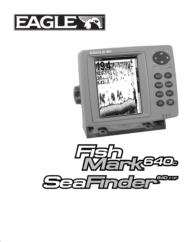
3. The transducer should be installed with its face pointing straight
down, if possible. For shoot-thru applications: Many popular fishing
boat hulls have a flat keel pad that offers a good mounting surface. On
vee hulls, try to place the transducer where the deadrise is 10° or less.
°
Pad
Left, vee pad hull; right, vee hull. A pod style transducer is shown here,
but the principle is the same for Skimmers inside a hull.
Strakes
4. If the transducer is mounted on the transom, make sure it doesn't interfere with the trailer or hauling of the boat. Also, don't mount it
closer than approximately one foot from the engine's lower unit. This
will prevent cavitation (bubble) interference with propeller operation.
9
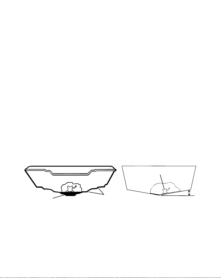
5. If possible, route the transducer cable away from other wiring on the
prevent the transducer from
location
Transom
Transom
centerline
boat. Electrical noise from engine wiring, bilge pumps and aerators can
be displayed on the sonar's screen. Use caution when routing the transducer cable around these wires.
CAUTION: Clamp the transducer cable to transom near
the transducer. This will help
entering the boat if it is
knocked off at high speed.
Poor location
Good
Good location
Poor angle
Good and poor transducer locations.
Good location
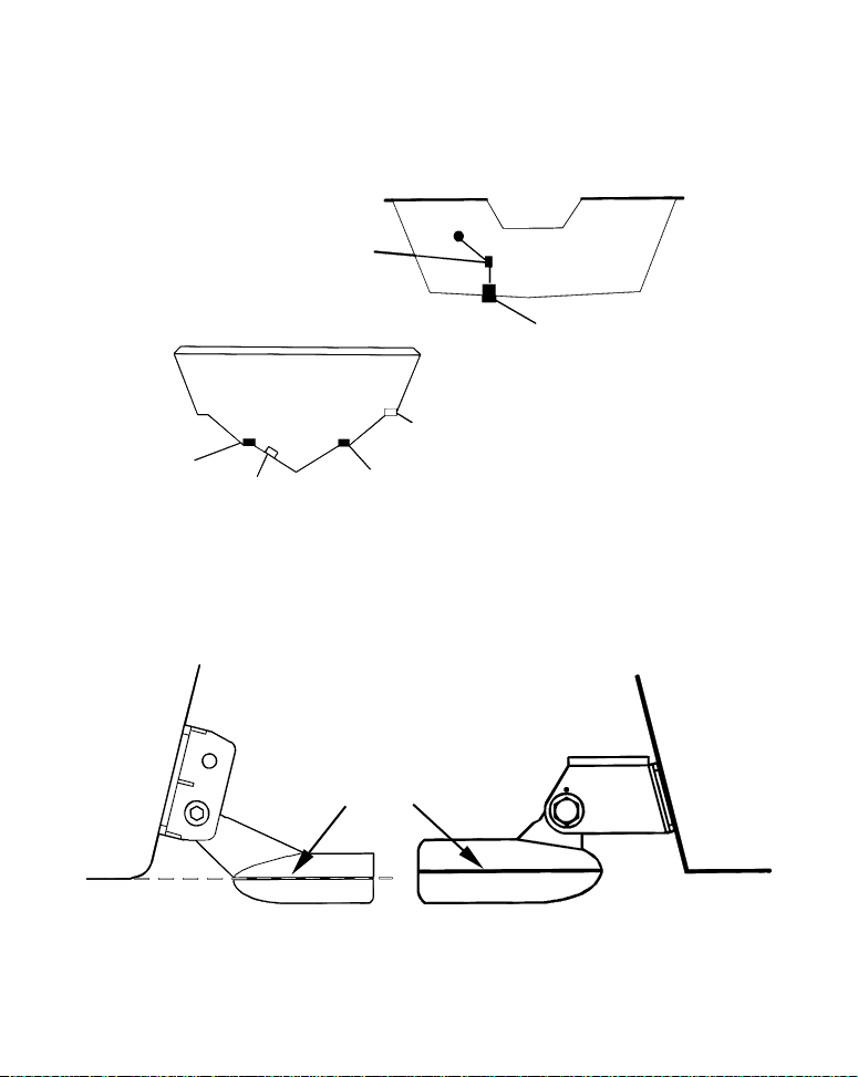
How low should you go?
For most situations, you should install your Skimmer transducer so
that its centerline is level with the bottom of the boat hull. This will
usually give you the best combination of smooth water flow and protection from bangs and bumps.
Hull bottom
Align transducer centerline with hull bottom. A dual frequency trans-
ducer is shown at left and a single frequency transducer at right.
Transducer
10
Hull bottom

However, there are times when you may need to adjust the transducer
slightly higher or lower. The slots in the mounting brackets allow you
to loosen the screws and slide the transducer up or down. If you frequently lose bottom signal lock while running at high speed the transducer may be coming out of the water as you cross waves or wakes.
Move the transducer a little lower to help prevent this.
If you cruise or fish around lots of structure and cover, your transducer
may be frequently kicking up from object strikes. If you wish, you may
move the transducer a little higher for more protection.
There are two extremes you should avoid. Never let the edge of the
mounting bracket extend below the bottom of the hull. Never let the
bottom – the face – of the transducer rise above the bottom of the hull.
Shoot-Thru-Hull vs. Transom Mounting
In a shoot-thru-hull installation, the transducer is bonded to the inside
of the hull with epoxy. The sonar "ping" signal actually passes through
the hull and into the water. This differs from a bolt-thru-hull installation (often called "thru-hull"). In that case, a hole is cut in the hull and
a specially designed transducer is mounted through the hull with a
threaded shaft and nut. This puts the transducer in direct contact with
the water.
Typically, shoot-thru-hull installations give excellent high speed operation and good to excellent depth capability. There is no possibility of
transducer damage from floating objects, as there is with a transommounted transducer. A transducer mounted inside the hull can't be
knocked off when docking or loading on a trailer.
However, the shoot-thru-hull installation does have its drawbacks.
First, some loss of sensitivity does occur, even on the best hulls. This
varies from hull to hull, even from different installations on the same
hull. This is caused by differences in hull lay-up and construction.
Second, the transducer angle cannot be adjusted for the best fish arches
on your sonar display.
11

Lack of angle adjustment can be particularly troublesome on hulls that
sit with the bow high when at rest or at slow trolling speeds.
Third, a transducer CAN NOT shoot through wood and metal hulls.
Those hulls require either a transom mount or a thru-hull installation.
Fourth, if your Skimmer transducer has a built in temp sensor, it will
only show the temperature of the bilge, not the water surface temp.
Follow the testing procedures listed in the shoot-thru-hull installation
section at the end of this instruction booklet to determine if you can
satisfactorily shoot through the hull.
Transom Transducer Assembly and Mounting
The best way to install these transducers is to loosely assemble all of
the parts first, place the transducer's bracket against the transom and
see if you can move the transducer so that it's parallel with the ground.
The following instructions sometimes vary depending on the mounting
bracket that came with your transducer. Single frequency Skimmers
come with a one-piece stainless steel bracket, while dual frequency
Skimmers come with a two-piece plastic mounting bracket. Use the set
of instructions that fits your model.
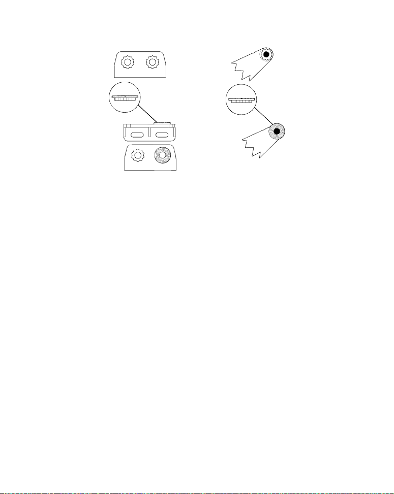
1. Assembling the bracket.
A. One-piece bracket: Press the two small plastic ratchets into the sides
of the metal bracket as shown in the following illustration. Notice there are
letters molded into each ratchet. Place each ratchet into the bracket with
the letter "A" aligned with the dot stamped into the metal bracket. This position sets the transducer's coarse angle adjustment for a 14° transom. Most
outboard and stern-drive transoms have a 14° angle.
12
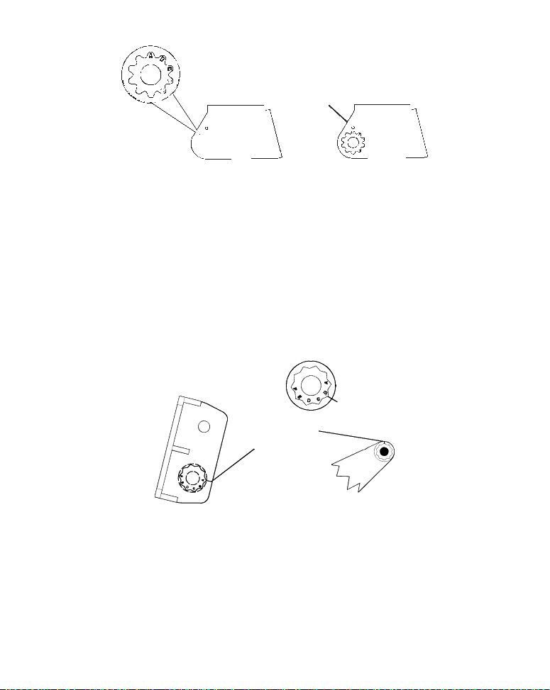
Dot
ducer
Align plastic ratchets in bracket.
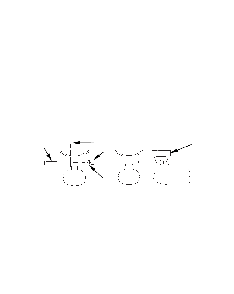
B. Two-piece bracket: Locate the four plastic ratchets in the transducer's hardware package. Press two ratchets into the sides of the plastic
bracket and two on either side of the transducer as shown in the following illustrations. Notice there are letters molded into each ratchet. Place
the ratchets into the bracket with the letter "A" aligned with the alignment mark molded into the bracket. Place the ratchets onto the transducer with the letter "A" aligned with the 12 o'clock position on the
transducer stem. These positions set the transducer's coarse angle adjustment for a 14° transom. Most outboard and stern-drive transoms
have a 14° angle.
Alignment letters
Alignment
positions
Trans
bracket
Transducer
Insert and align ratchets.
13
Transducer bracket
Transducer
Ratchet
Add ratchets to bracket and transducer.
Ratchet
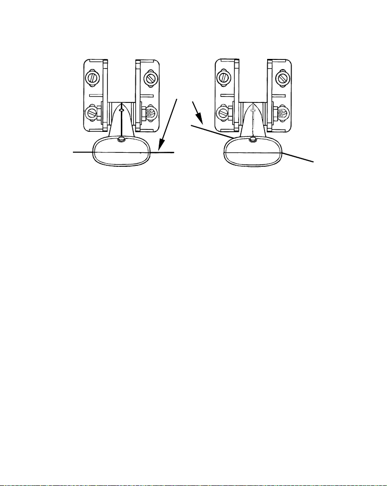
2. Aligning the transducer on the transom.
A. One-piece bracket: Slide the transducer between the two ratch-
ets. Temporarily slide the bolt though the transducer assembly and
hold it against the transom. Looking at the transducer from the side,
check to see if it will adjust so that its face is parallel to the ground.
If it does, then the "A" position is correct for your hull.
If the transducer's face isn't parallel with the ground, remove the
transducer and ratchets from the bracket. Place the ratchets into the
holes in the bracket with the letter "B" aligned with the dot stamped
in the bracket.
Reassemble the transducer and bracket and place them against the
transom. Again, check to see if you can move the transducer so it's parallel with the ground. If you can, then go to step 3A. If it doesn't, repeat
step 2A, but use a different alignment letter until you can place the
transducer on the transom correctly.
14
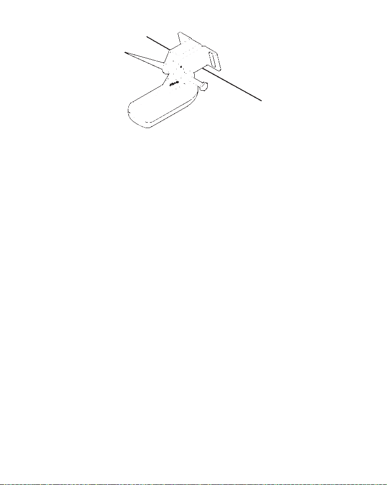
Ratchets
Insert bolt and check transducer position on transom.
B. Two-piece bracket: Assemble the transducer and bracket as
shown in the following figure. Temporarily slide the bolt though the
transducer assembly but don't tighten the nut at this time. Hold the
assembled transducer and bracket against the transom. Looking at the
transducer from the side, check to see if it will adjust so that its face is
parallel to the ground. If it does, then the "A" positions are correct for
your hull.
If the transducer's face isn't parallel with the ground, remove and
disassemble the transducer and ratchets. Place the ratchets into the
bracket holes with the letter "B" aligned with the bracket alignment
mark. Place them on the transducer aligned with the 12 o'clock position on the transducer stem.
Reassemble the transducer and bracket and place them against the
transom. Again, check to see if you can move the transducer so it's
parallel with the ground. If you can, then go to step 3B. If it doesn't,
repeat step 2B, but use a different alignment letter until you can
place the transducer on the transom correctly.
15
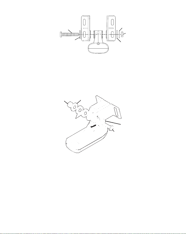
Flat washer
Bolt
Flat washer
Assemble transducer and bracket.
Lock washer
Nut
3. Assembling the transducer.
A. One-piece bracket: Once you determine the correct position for the
ratchets, assemble the transducer as shown in the following figure.
Don't tighten the lock nut at this time.
Metal
Nut
washer
Rubber
washers
Assemble transducer and bracket.
Metal washer
Bolt
B. Two-piece bracket: Once you determine the correct position for the
ratchets, assemble the transducer as shown in the figure in step 2B.
Don't tighten the lock nut at this time.
4. Drilling mounting holes.
Hold the transducer and bracket assembly against the transom. The
transducer should be roughly parallel to the ground. The transducer's centerline should be in line with the bottom of the hull. Don't
let the bracket extend below the hull!
16
Mark the center of each slot for the mounting screw pilot holes. You
will drill one hole in the center of each slot.
Drill the holes. For the one-piece bracket, use the #29 bit (for the #10
screws). For the two-piece bracket, use the #20 bit (for the #12
screws).
Transom
Transom
Position transducer mount on transom and mark mounting holes.
Side view shown at left and seen from above at right.
5. Attaching transducer to transom.
A. One-piece bracket: Remove the transducer from the bracket and reassemble it with the cable passing through the bracket over the bolt as
shown in the following figures.
For single-frequency Skimmer, route cable over bolt and through
bracket. Side view shown at left and seen from above at right.
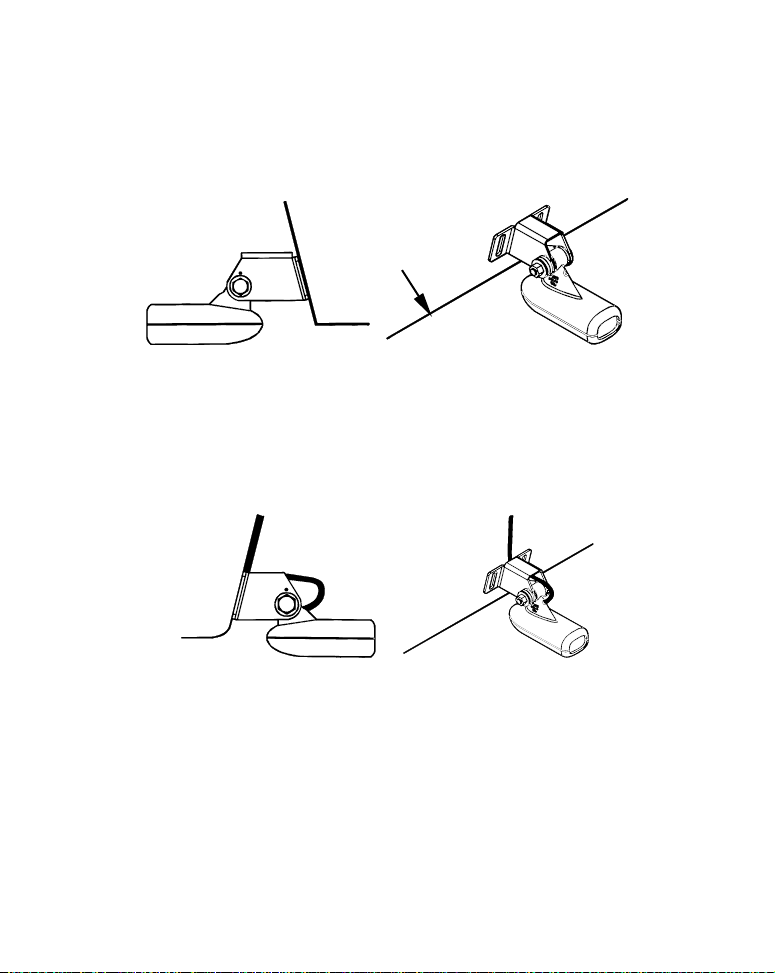
Both bracket types: Attach the transducer to the transom. Slide the
transducer up or down until it's aligned properly with the bottom of the
hull as shown in the preceding and following figures. Tighten the
bracket's mounting screws, sealing them with the caulking compound.
Adjust the transducer so that it's parallel to the ground and tighten the
nut until it touches the outer washer, then add 1/4 turn. Don't over
17
tighten the lock nut! If you do, the transducer won't "kick-up" if it
Flat-bottom hull
strikes an object in the water.
Bottom
of
hull
Deep-"vee" hull
Align transducer centerline with hull bottom and attach transducer to
transom. Rear view of dual-frequency Skimmer shown.
6. Route the transducer cable through or over the transom to the sonar
unit. Make sure to leave some slack in the cable at the transducer. If
possible, route the transducer cable away from other wiring on the boat.
Electrical noise from the engine's wiring, bilge pumps, VHF radio wires
and cables, and aerators can be picked up by the sonar. Use caution
when routing the transducer cable around these wires.
WARNING:
Clamp the transducer cable to the transom close to the
transducer. This can prevent the transducer from entering the boat if it is knocked off at high speed.
If you need to drill a hole in the transom to pass the connector through,
the required hole size will be 5/8".
18
Caution:
Flat washer
If you drill a hole in the transom for the cable, make sure it is located above the waterline. After installation, be sure to seal the
hole with the same marine grade above- or below-waterline sealant used for the mounting screws.
7. Make a test run to determine the results. If the bottom is lost at
high speed, or if noise appears on the display, try sliding the transducer
bracket down. This puts the transducer deeper into the water, hopefully below the turbulence causing the noise. Don't allow the transducer
bracket to go below the bottom of the hull!
Trolling Motor Bracket Installation
(single-frequency only)
1. Attach the optional TMB-S bracket to the transducer as shown in the
following figure, using the hardware supplied with the transducer.
(Note: The internal tooth washer is supplied with the TMB-S.)
Bolt
Attach motor mounting bracket to transducer.
Internal tooth washer
Nut
2. Slide the adjustable strap supplied with the TMB-S through the slot
in the transducer bracket and wrap it around the trolling motor. Position the transducer to aim straight down when the motor is in the water. Tighten the strap securely.
3. Route the transducer cable alongside the trolling motor shaft. Use
plastic ties (not included) to attach the transducer cable to the trolling
motor shaft. Make sure there is enough slack in the cable for the motor
to turn freely. Route the cable to the sonar unit and the transducer is
ready for use.
19
TMB-S bracket
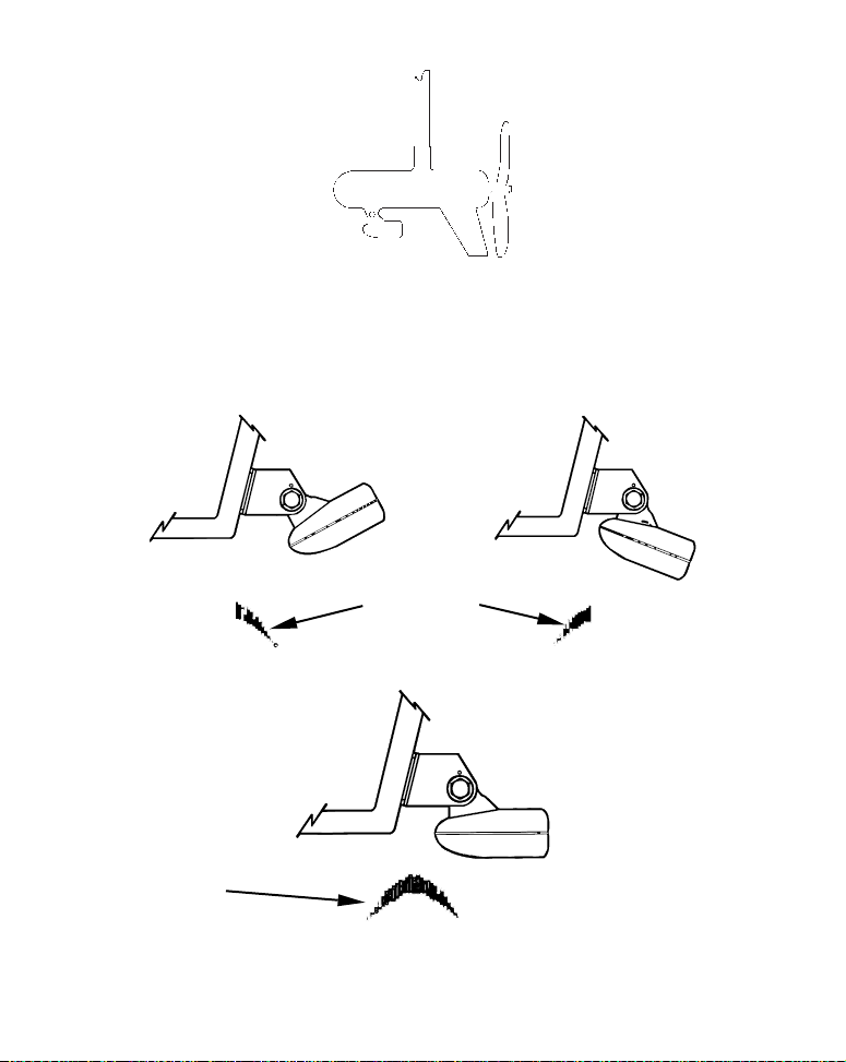
Transducer mounted on trolling motor, side view.
Transducer Orientation and Fish Arches
If you do not get good fish arches on your display, it could be because
the transducer is not parallel with the ground when the boat is at rest
in the water or at slow trolling speeds.
Partial fish arches
Transducer aimed
too far back
Full fish arch
Transducer angles and their effects on fish arches.
Proper transducer angle
20
Transducer aimed
too far forward
If the arch slopes up – but not back down – then the front of the transducer is too high and needs to be lowered. If only the back half of the
arch is printed, then the nose of the transducer is angled too far down
and needs to be raised.
NOTE:
Periodically wash the transducer's face with soap and water to remove any oil film. Oil and dirt on the face will reduce the sensitivity
or may even prevent operation.
Shoot-Thru-Hull Preparation
Hulls With Flotation Materials
The transducer installation inside a fiberglass hull must be in an area
that does not have air bubbles in the resin or separated fiberglass layers. The sonar signal must pass through solid fiberglass. A successful
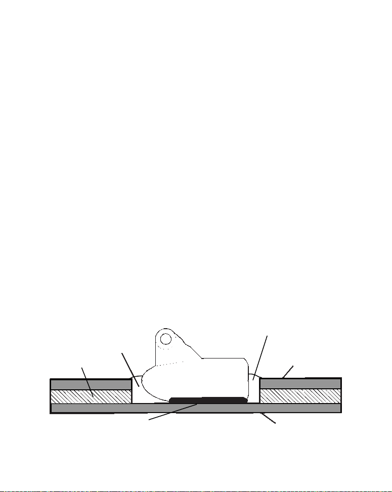
transducer installation can be made on hulls with flotation materials
(such as plywood, balsa wood or foam) between layers of fiberglass if
the material is removed from the chosen area. See the figure below.
WARNING:
Do not remove any material from your inner hull unless
you know the hull's composition. Careless grinding or
cutting on your hull can result in damage that could
sink your boat. Contact your boat dealer or manufacturer to confirm your hull specifications.
Fill with resin
Flotation material
Epoxy to hull first
Epoxy the transducer to a solid portion of the hull.
Fill with resin
Inner hull
Outer hull
21
For example, some (but not all) manufacturers use a layer of fiberglass,
then a core of balsa wood, finishing with an outer layer of fiberglass. Removing the inner layer of fiberglass and the balsa wood core exposes the
outer layer of fiberglass. The transducer can then be epoxied directly to
the outer layer of fiberglass. After the epoxy cures for 24 hours, fill the
remaining space with polyester resin. When the job is finished, the hull
is watertight and structurally sound. Remember, the sonar signal must
pass through solid fiberglass. Any air bubbles in the fiberglass or the epoxy will reduce or eliminate the sonar signals.
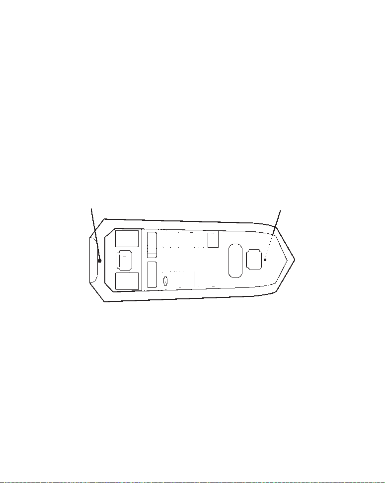
Testing Determines Best Location
Ideally, the shoot-thru transducer should be installed as close to the
transom as possible, close to the centerline. This will give you the best
performance during high speed maneuvers.
Transducer location
(high speed)
Shoot-thru-hull transducer locations for
high speed or trolling speed operation.
Transducer location
(trolling speed)
To choose the proper location for shoot-thru-hull mounting, follow these
testing procedures: (You may need a helper to complete these steps.)
1. Anchor the boat in about 30 feet of water. Add a little water to the
sump of the boat. Plug the transducer into the sonar unit, turn it on, then
hold the transducer over the side of the boat in the water. Adjust the sensitivity and range controls until a second bottom echo is seen on the display. You'll need to turn off Auto Sensitivity, Auto Depth Range and
ASP. Try a range setting that is two to three times the water depth. The
22
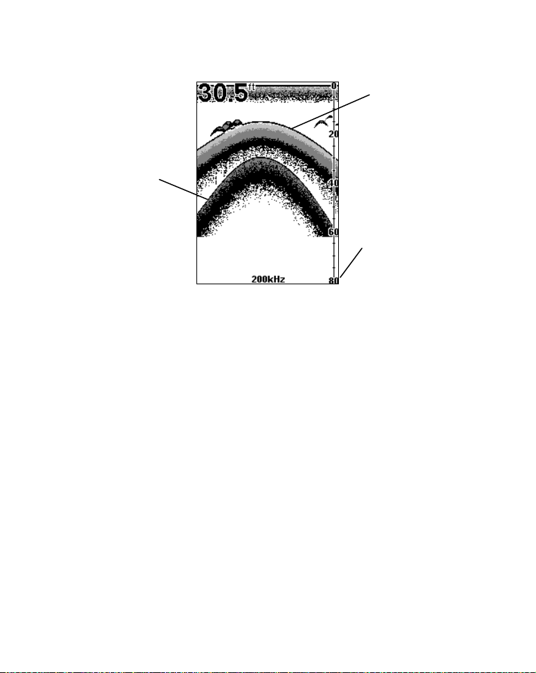
harder (more rocky) the bottom, the easier it will be to get a second bot-
Second bottom
True bottom
tom signal. Don't touch the controls once they've been set.
Manual range setting
Example of a second bottom signal. Unit is in 30 feet of water, with
range set at 80 feet and sensitivity set at 87 percent
2. Next, take the transducer out of the water and place it in the water
in the sump of the boat, face down. (The transducer face is shown in the
figure on page 25.) Notice how the signal strength decreases. The second bottom signal will probably disappear and the bottom signal intensity will likely decrease.
3. Now move the transducer around to find the best location with the
strongest possible bottom signal. If you find a spot with an acceptable
bottom signal, mark the location and move on to step 4.
If you can't get an acceptable bottom signal, try turning up the sensitivity
by three or five keystrokes and then move the transducer around once
more. If you find a spot that works, mark it and move on to step 4.
If you have to turn up sensitivity by more than five keystrokes to get a
good signal, the transducer should be mounted on the outside of the
hull. This is especially true if you have to turn sensitivity all the way
up to get a decent bottom signal.
23

4. Most people can get good results by following steps 1 through 3, so this
step is optional. If you want to make an extra effort to be absolutely sure
that your selected location will work under all conditions, make a test run
with the boat on plane and observe the bottom signal. You'll need to figure
some way to prop the transducer into position while you make your test
run. (A brick or two might be sufficient to hold it in place.)
5. When you're satisfied with a location, mark it and proceed with the
installation.
Shoot-Thru-Hull Installation
If you are installing the transducer on a hull with floatation material
sandwiched within the hull, refer to the text "Hulls With Flotation Materials" beginning on page 22.
1. Make sure the area is clean, dry and free of oil or grease, then sand
both the inside surface of the hull and the face of the transducer with
100 grit sandpaper. The sanded hull area should be about 1-1/2 times
the diameter of the transducer. The surface of the hull must be flat so
the entire transducer face is in contact with the hull prior to bonding.
After sanding, clean the hull and transducer with rubbing alcohol to
remove any sanding debris.
24
 Loading...