


FishElite 500C
Pub. 988-0156-041
www.eaglesonar.com
FishElite 500C and
SeaCharter 500CDF
Fish-finding Sonars & Mapping GPS
Installation and Operation
Instructions

Copyright © 2004 LEI-Eagle
All rights reserved.
No part of this manual may be copied, reproduced, republished,
transmitted or distributed for any purpose, without prior written
consent of Eagle Electronics. Any unauthorized commercial
distribution of this manual is strictly prohibited.
Eagle
®
, FishElite
500C and SeaCharter
500CDF are registered
trademarks of LEI. MapCreate, FreedomMaps, IMS and
NauticPaths are trademarks of LEI. Fishing Hot Spots
is a
registered trademark of Fishing Hot Spots Inc. Navionics
is a
registered trademark of Navionics, Inc.
eXitSource Database, copyright 2001-2003 Zenrin Co.
Ltd. Exit Authority and eXitSource are trademarks of
Zenrin Co. Ltd.
Eagle Electronics may find it necessary to change or end our policies,
regulations, and special offers at any time. We reserve the right to do so
without notice. All features and specifications subject to change without
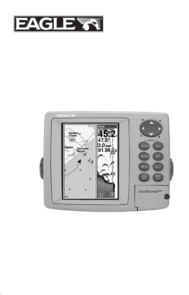
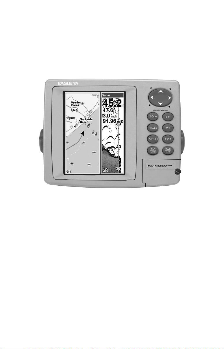
notice. All screens in this manual are simulated. On the cover:
SeaCharter 500CDF shown. Other models covered in the manual are
similar.
For free owner's manuals and the most current information on
this product, its operation and accessories,
visit our web site:
www.eaglesonar.com
Eagle Electronics
P.O. Box 669
Catoosa, OK USA 74015
Printed in USA.

i
Table of Contents
Section 1: Read Me First!......................................................... 1
Capabilities and Specifications:
FishElite
500C and SeaCharter
500CDF ................................. 3
How Eagle Sonar Works............................................................... 5
How Eagle GPS Works ................................................................. 6
Introduction to GPS and WAAS................................................... 8
How to use this manual: typographical conventions ................ 11
Section 2: Installation & Accessories..................................15
Preparations................................................................................ 15
Transducer Installation.............................................................. 15
Selecting a Transducer Location............................................ 16
How Low Should You Go?....................................................... 17
Shoot-Thru-Hull vs. Transom Mounting ............................... 18
Transom Transducer Assembly and Mounting ..................... 19
Trolling Motor Bracket Installation....................................... 24
Transducer Orientation and Fish Arches .............................. 25
Shoot-Thru-Hull Preparation and Installation ..................... 26
Speed/Temperature Sensors....................................................... 29
Power Connections...................................................................... 32
Mounting the Unit: Bracket, In-Dash or Portable .................... 33
GPS Antenna/Receiver Module Installation.............................. 37
NMEA Cable Connections .......................................................... 38
NMEA Wiring ......................................................................... 38
MMC or SD Card Memory Card Installation ............................ 38
Other Accessories........................................................................ 39
Section 3: Basic Sonar Operation ........................................ 41
Keyboard ..................................................................................... 41
Power/lights on and off ............................................................... 42
Main Menu .................................................................................. 42
Pages ........................................................................................... 44
Satellite Status Page .............................................................. 44
Navigation Page...................................................................... 45
Map Page................................................................................. 45
Sonar Page .............................................................................. 46
Basic Sonar Quick Reference ............................................... 49
Sonar Operations ........................................................................ 50
Fish Symbols vs. Full Sonar Chart ........................................ 52
Section 4: Sonar Options & Other Features ...................... 53
ASP (Advanced Signal Processing) ..................................... 53
Alarms ......................................................................................... 54
Depth Alarms .......................................................................... 54
Zone Alarm .............................................................................. 55

ii
Fish Alarm............................................................................... 56
Calibrate Speed........................................................................... 57
Chart Speed................................................................................. 58
ColorLine.................................................................................. 59
Customize Page Displays ........................................................... 60
Depth Cursor............................................................................... 61
Depth Range - Automatic ........................................................... 62
Depth Range - Manual................................................................ 63
FasTrack .................................................................................. 63
Fish I.D. (Fish Symbols & Depths) ......................................... 64
FishTrack ................................................................................. 65
Frequency (Change Transducer Frequency) .............................66
HyperScroll .............................................................................. 67
Log Sonar Chart Data ................................................................ 67
Noise Rejection............................................................................ 68
Overlay Data ............................................................................... 68
Ping Speed & HyperScroll....................................................... 72
Reset Options .............................................................................. 73
Reset Water Distance ................................................................. 74
Set Keel Offset ............................................................................74
Sensitivity & Auto Sensitivity.................................................... 75
To turn Auto Sensitivity back on: ..........................................76
Sonar Chart Mode (change chart color scheme)........................ 77
Sonar Page & Sonar Chart Display Options ............................. 77
Full Sonar Chart ..................................................................... 77
Split Zoom Sonar Chart.......................................................... 78
Digital Data............................................................................. 79
Map With Sonar Split Screen................................................. 81
Sonar Simulator.......................................................................... 81
Stop Chart ................................................................................... 83
Surface Clarity............................................................................ 84
Zoom & Zoom Bar ....................................................................... 85
Zoom Pan..................................................................................... 86
Section 5: Sonar Troubleshooting .......................................87
Section 6: Basic GPS Operations ......................................... 91
Keyboard ..................................................................................... 91
Power/lights (Turn Unit On and Off)......................................... 92
Main Menu .................................................................................. 92
Pages ........................................................................................... 94
Sonar Page .............................................................................. 94
Satellite Status Page .............................................................. 94
Navigation Page...................................................................... 96
Map Page................................................................................. 98

iii
Background map vs. MapCreate map content ................ 100
Resize Window command ..................................................... 102
Basic GPS Quick Reference ................................................ 104
Find Your Current Position...................................................... 105
Moving Around the Map: Zoom & Cursor Arrow Keys ........... 105
Selecting Any Map Item With the Cursor ............................... 106
Searching................................................................................... 106
Set a Waypoint.......................................................................... 109
Create Waypoint at Current Position .............................. 109
Create Waypoint on Map .................................................. 110
Create Waypoint by Entering a Position ......................... 110
Navigate To a Waypoint ........................................................... 111
Set Man Overboard (MOB) Waypoint...................................... 112
Navigate Back to MOB Waypoint ............................................ 112
Navigate to Cursor Position on Map........................................ 113
Navigate to a Point of Interest................................................. 115
Creating and Saving a Trail..................................................... 115
Displaying a Saved Trail .......................................................... 117
Navigating Trails...................................................................... 117
Visual Trailing ...................................................................... 118
Navigate a Trail (forward).................................................... 118
Navigate a Back Trail (backtrack, or reverse)..................... 120
Transfer Custom Maps and GPS Data Files ........................... 121
Cancel Navigation..................................................................... 123
Section 7: Advanced GPS Operations ............................... 125
Find Distance From Current Position To Another Location .. 125
Find Distance From Point to Point .......................................... 125
Icons........................................................................................... 126
Create Icon on Map............................................................... 126
Create Icon at Current Position ........................................... 126
Delete an Icon ....................................................................... 127
Navigate to an Icon............................................................... 127
Routes........................................................................................ 128
Create and Save a Route ......................................................128
Delete a Route ....................................................................... 131
Edit a Route Name................................................................ 131
Edit Route Waypoints........................................................... 131
Navigate a Route................................................................... 132
Navigate a Route in Reverse ................................................ 133
Trails ......................................................................................... 134
Delete a Trail ........................................................................ 134
Edit a Trail Name ................................................................. 134
Edit a Trail Color .................................................................. 135

iv
Edit a Trail Pattern .............................................................. 135
Utilities...................................................................................... 136
Alarm Clock........................................................................... 136
Sun/Moon Rise & Set Calculator.......................................... 136
Trip Calculator...................................................................... 136
Trip Down Timer................................................................... 136
Trip Up Timer ....................................................................... 136
Waypoints.................................................................................. 136
Delete a Waypoint................................................................. 136
Edit a Waypoint (Name, Symbol, Position) ......................... 137
Selecting a Waypoint ............................................................ 137
Set a Waypoint by Average Position .................................... 138
Set a Waypoint by Projecting a Position.............................. 138
Section 8: System & GPS Setup Options .......................... 139
Alarms ....................................................................................... 139
Check MMC Files and Storage Space...................................... 140
Communications Port Configuration ....................................... 140
Configure NMEA ...................................................................... 141
Coordinate System Selection.................................................... 142
To setup Loran TD: ............................................................... 143
Map Fix ..................................................................................... 144
Customize Page Displays ......................................................... 145
GPS Simulator .......................................................................... 145
Simulating Trail or Route Navigation ................................. 146
Hide GPS Features ................................................................... 147
Initialize GPS............................................................................ 147
Map Auto Zoom......................................................................... 147
Map Data................................................................................... 148
Show Map Data..................................................................... 148
Pop-up Map Information ...................................................... 148
Map Boundaries .................................................................... 149
Fill Water With White .......................................................... 149
Map Overlays (Range Rings; Lat/Long Grid) ...................... 149
Map Datum Selection ............................................................... 150
Map Detail Category Selection................................................. 150
Map Orientation ....................................................................... 151
Navionics
Charts..................................................................... 152
Display a Navionics chart:.................................................... 152
Port Information ...................................................................153
Tidal Current Information ................................................... 154
Tide Information ................................................................... 156
Pop-up Help............................................................................... 158
Reset Options ............................................................................ 158

v
Require WAAS .......................................................................... 159
Screen Contrast and Brightness .............................................. 159
Set Language ............................................................................ 160
Set Local Time .......................................................................... 161
Show WAAS Alarm................................................................... 161
Software Version Information.................................................. 162
Sounds and Alarm Sound Styles.............................................. 162
Track Smoothing....................................................................... 163
Trail Options ............................................................................. 164
Delete All Trails .................................................................... 164
Update Trail Options ............................................................ 164
Delete Trail ........................................................................... 166
New Trail............................................................................... 166
Trail Visible/Invisible and Other Trail Options .................. 166
Transparency ............................................................................ 166
Units of Measure....................................................................... 167
Section 9: Searching .............................................................169
Find Addresses.......................................................................... 170
Find Any Item Selected by Map Cursor .................................. 173
Find Interstate Highway Exits ................................................ 173
Find Map Places or Points of Interest (POI) ...........................176
Find Streets or Intersections.................................................... 178
Find Waypoints......................................................................... 182
Section 10: Supplemental Material ...................................185

vi
WARNING!
A CAREFUL NAVIGATOR NEVER RELIES ON ONLY ONE METHOD
TO OBTAIN POSITION INFORMATION.
CAUTION
When showing navigation data to a position (waypoint), a GPS unit will show
the shortest, most direct path to the waypoint. It provides navigation data to the
waypoint regardless of obstructions. Therefore, the prudent navigator will not
only take advantage of all available navigation tools when traveling to a way-
point, but will also visually check to make sure a clear, safe path to the waypoint
is always available.
WARNING!
When a GPS unit is used in a vehicle, the vehicle operator is solely re-
sponsible for operating the vehicle in a safe manner. Vehicle operators
must maintain full surveillance of all pertinent driving, boating or fly-
ing conditions at all times. An accident or collision resulting in damage
to property, personal injury or death could occur if the operator of a
GPS-equipped vehicle fails to pay full attention to travel conditions and
vehicle operation while the vehicle is in motion.

1
Section 1: Read Me First!
How this manual can get you out on the road, fast!
Welcome to the exciting world of digital sonar and GPS! We know
you're anxious to begin navigating and finding fish, but we have a favor
to ask. Before you grab the unit and begin installing it, please give us a
moment or two to explain how our manual can help you get the best
performance from your compact, color display, combination fish finder
and mapping GPS receiver.
First, we want to thank you for buying a Eagle sonar/GPS unit.
Whether you're a first time user or a professional fisherman, you'll dis-
cover that your unit is easy to use, yet capable of handling demanding
navigation and sonar tasks. When you team your unit with our custom
mapping software MapCreate 6, you have an incredible combination.
You won't find another combination GPS and sonar unit with this much
power and this many features for this price!
Our goal for this book is to get you on the water fast, with a minimum
of fuss. Like you, we'd rather spend more time boating or fishing and
less time reading the manual!
So, we designed our book so that you don't have to read the whole thing
from front to back for the information you want. At the start (or end) of
each segment, we'll tell you what content is coming up next. If it's a
concept you're already familiar with, we'll show you how and where to
skip ahead for the next important topic. We've also made it easy to look
up any tips you may need from time to time. Here's how:
The manual is organized into 10 sections. This first section is an intro-
duction to the FishElite
500C or SeaCharter
500CDF, sonar and
GPS. It tells you the basics you need to know before you can make the
unit look around and tell you where you are, or look below the surface
to find some fish.
Section 2 will help you install your unit, the transducer and the GPS
antenna module. We'll show you how to get the MultiMedia Card
(MMC) correctly installed inside the unit. We'll also tell you about some
of the available accessories.
Section 3 covers Basic Sonar Operation. It will show you how easy it is
to run your unit, right out of the box. This section features a one-page
Sonar Quick Reference. (If you've already jumped ahead and fig-
ured out how to install the unit yourself, and you just can't wait
any longer, turn to the Quick Reference on page 49 and head

2
for the water with your unit!)
After you've gained some experience with your sonar, you'll want to
check out Section 4, which discusses more advanced Sonar Options and
Other Features.
When you come to a sonar menu command on the unit's screen, you can
look it up in the manual by skimming over the table of contents, just flip-
ping through Section 3 or scanning through the sonar options in Section 4.
If you're having difficulty with your sonar, you can find an answer to
the most common problems in Section 5, Sonar Troubleshooting.
The manual switches from sonar to navigation in Section 6, which in-
troduces you to Basic GPS Operations. This section features a one-
page GPS Quick Reference on page 104.
Section 6 contains short, easy-to-scan GPS lessons that follow one an-
other in chronological order. They're all you'll need to know to find your
way on the water quickly.
After you've learned the basics (or if you already have some GPS expe-
rience), you may want to try out some of the unit's many advanced
navigation features. That brings us to Section 7, Advanced GPS Opera-
tions. This section contains the rest of the unit's GPS command func-
tions, organized in alphabetical order.
When you come to a GPS menu command on the screen, you can look it
up in the manual by skimming over the table of contents, just flipping
through Section 6 or scanning through the command portion of Section 7.
This unit is ready to use right out of the box, but you can fine tune and
customize it's operation with dozens of options. Since sonar is the unit's
key feature, we put the main sonar options in Section 4. Some options,
such as screen brightness settings, affect both sonar and GPS opera-
tions. We describe how to use those common options along with GPS
options in Section 8, System Setup and GPS Setup Options. Section 8 is
organized in alphabetical order.
In Section 9, we go into more detail on one of the unit's most remarkable
GPS capabilities — Searching. We'll introduce a search example in the Ba-
sic GPS Operation section, but there are so many map items you can
search for, we had to give this function it's own section in the manual! For
example, did you know this unit can look up business phone numbers,
functioning as a virtual Yellow Pages? We’ll show you how in Section 9.
Finally, in Section 10, we offer Supplemental Material, including a list

3
of the GPS datums used, warranties and customer service information.
Now, if you're into the fine details, glance over the next segment on
specifications to see just how much sonar and GPS power your unit con-
tains. It's important to us (and our power users), but, if you don't care
how many watts of power the unit has, or how many waypoints it can
store, skip ahead to important information on how the sonar works, on
page 5. (Background on GPS begins on page 6.)
Capabilities and Specifications: FishElite 500C and SeaChar-
ter 500CDF
General
Display:............................ 5.0" (12.7 cm) diagonal color TFT LCD; pro-
grammable to viewing preference.
Resolution:...................... 320 pixel x 240 pixel resolution; 76,800 total
pixels.
Backlighting:.................. Backlit screen and keypad with multiple
lighting levels for night use.
Input power:................... 10 to 15 volts DC.
Case size:......................... 5.4" H x 6.9" W x 3.4" D (13.8 x 17.6 x 8.6
cm); sealed and waterproof; suitable for
saltwater use.
Back-up memory: .......... Built-in memory stores sonar records for
decades.
Languages:...................... 10; menu languages selectable by user.
Sonar
Frequency:...................... 50/200 kHz for SeaCharter 500CDF; 200 kHz
for FishElite 500C.
Transducers: .................. A dual-frequency Skimmer
transducer with
built-in temperature sensor is packed with
the SeaCharter 500CDF. It has 35°/12° cone
angles. A single-frequency Skimmer trans-
ducer with built-in temperature sensor is
packed with the FishElite 500C. It has a 20°
cone angle. Transducers operate at speeds up
to 70 mph (61 kts)
Watts: ............................... 1,500 watts peak-to-peak/188 watt RMS.
Sonar sounding
depth capability: ........... SeaCharter 500CDF: 1,500 feet (450 me-
ters). FishElite 500C: 800 feet (244 meters).
Actual capability depends on transducer con-

4
figuration and installation, bottom composi-
tion and water conditions. All sonar units
typically read deeper in fresh water than in
salt water.
Depth display:................ Continuous display .
Audible alarms: ............. Deep/shallow/fish/zone.
Automatic ranging:....... Yes, with instant screen updates.
Auto bottom track:........ Yes.
Zoom bottom track: ...... Yes.
Split-screen zoom:......... Yes.
Surface water temp: ..... Yes.
Speed/distance log:...... Optional (requires optional speed sensor).
GPS
MMC slots: ...................... One with waterproof door (SD card
compatible).
Recording:........................ MMC & SD cards for recording GPS trip de-
tails and displaying charts or custom maps.
GPS
Receiver/antenna: ......... External; EGC-12w 12 parallel channel
GPS/WAAS.
Background map:.......... Built-in custom, detailed Eagle map. Con-
tains: enhanced detail of continental U.S.
and Hawaii. Includes more than 60,000 nav
aids and 10,000 wrecks/obstructions in
coastal and Great Lakes waters. Metro
areas, selected major streets/highways and
interstate exit services details included.
Custom mapping: .......... MapCreate
6 software optional; optional
plug and play LEI FreedomMaps offer the
same high-detail without the computer work
of MapCreate. Other plug and play mapping
options include IMS Fishing Hot Spots
,
LEI NauticPaths charts and Navionics
charts.
Mapping memory: ......... Up to 1 gigabyte on one MMC (or SD) card.
Position updates: .......... Every second.
Position points: ............. 1,000 waypoints; 1,000 event marker icons.

5
Audible alarms: ............. Arrival/off-course/anchor.
Graphic symbols for
waypoints or event
marker icons: ................. 42.
Routes:............................. 100, up to 100 waypoints per route.
Plot Trails: ...................... 10 savable; up to 10,000 points per trail.
Zoom range:.................... 40 ranges; 0.02 to 4,000 miles.
NOTE:
The above memory capacities refer only to the unit’s on-board mem-
ory. The amount of GPS data you can record and save for recall later
is limited only by the number of MMC cards you have.
NOTICE!
The storage temperature range for your FishElite 500C and SeaCharter
500CDF is from -4 degrees to +167 degrees Fahrenheit (-20 degrees to
+75 degrees Celsius). Extended storage in temperatures higher or lower
than specified will damage the liquid crystal display in your unit. This
type of damage is not covered by the warranty. For more information,
contact the factory's Customer Service Department; phone numbers are
listed on the last page of this manual.
How Eagle Sonar Works
Sonar has been around since the 1940s, so if you already know how it
works, skip down to read about the relatively new technology of GPS.
But, if you've never owned a sonar fish finder, this segment will tell you
the under water basics.
Sonar is an abbreviation for SOund NA
vigation and Ranging, a technol-
ogy developed during World War II for tracking enemy submarines. Ea-
gle developed the world's first transistorized sportfishing sonar in 1957.)
A sonar consists of a transmitter, transducer, receiver and display. In
simple terms, here's how it finds the bottom, or the fish:
The transmitter emits an electrical impulse, which the transducer con-
verts into a sound wave and sends into the water. (The sound frequency
can't be heard by humans or fish.) The sound wave strikes an object
(fish, structure, bottom) and bounces back to the transducer, which
converts the sound back into an electrical signal.
The receiver amplifies this return signal, or echo, and sends it to the
display, where an image of the object appears on the scrolling sonar
chart. The sonar's microprocessor calculates the time lapse between the
transmitted signal and echo return to determine the distance to the

6
object. The whole process repeats itself several times each second.
Your unit can record a log of the sonar signals that scroll across the
screen and save them to the MMC memory card. (These recordings are
also called sonar charts or sonar graphs.) You can replay this sonar log
in the unit using the Sonar Simulator function, or play it back on a per-
sonal computer using our free Sonar Viewer or product emulator. The
viewer and emulator are available for download from the Eagle web
site, www.eaglesonar.com.
You can save several different sonar log files, erase 'em and record new
ones, over and over again. The size of your sonar recordings is only
limited by the free space available on your MMC.
How GPS Works
You'll navigate faster and easier if you understand how the unit scans
the sky to tell you where you are on the earth – and, where you're go-
ing. (But if you already have a working understanding of GPS receivers
and the GPS navigation system, skip on ahead to Section 2, Installation
& Accessories on page 15. If you're new to GPS, read on. You can later
impress your friends with your new-found knowledge.)
First, think of your unit as a small but powerful computer. (But don't
worry — we made it easy to use, so you don't need to be a computer ex-
pert to find your way!) The unit includes a keypad and a screen with
menus so you can tell it what to do. The screen also lets the unit show
your location on a moving map, as well as point the way to your desti-
nation.
This gimbal-mounted unit uses an external antenna/receiver module,
which makes the whole system work something like your car radio. But
instead of your favorite dance tunes, this receiver tunes in to a couple of
dozen GPS satellites circling the earth. (It will also listen in to the
WAAS satellites in orbit, but more about that in the upcoming segment
introducing you to GPS and WAAS.)
Your unit listens to signals from as many satellites as it can "see" above
the horizon, eliminates the weakest signals, then computes its location
in relation to those satellites. Once the unit figures its latitude and lon-
gitude, it plots that position on the moving map shown on the screen.
The whole process takes place several times a second!
The performance doesn't stop there. Stored in the permanent memory
of each unit is a basic background map of the entire world. We lock it in
here at the factory — you can't change or erase this map.
The background map is suitable for many navigation chores, but for
maximum accuracy and much more detail, you need our optional map-

7
making software, MapCreate 6. Some unit features — such as
searching for businesses and addresses — won't work without a custom
MapCreate map. There is so much detail in our background map (and
even more in MapCreate) that we'll describe their contents and differ-
ences in Section 3, Basic GPS Operations, on page 100.
Another portion of the SeaCharter 500CDF’s onboard memory is devoted
to recording GPS navigation information, which includes waypoints, event
marker icons, trails and routes. This lets you look back the way you came.
Think of this data storage like the hard drive memory in a computer or a
tape in a cassette tape recorder. You can save several different GPS data
files, erase 'em and record new ones, over and over again. Like any com-
puter file, these GPS Data Files (file format *.usr) can be shared be-
tween Eagle GPS or sonar/GPS units or even personal computers.
This unit has one more thing in common with a personal computer. Just
as computers have a floppy disk drive for storing and exchanging files,
the unit has a slot for an MMC (MultiMedia Card) or SD card (Secure
Digital card) flash memory card. These solid-state memory devices are
about the size of a postage stamp, but can hold data ranging from 8 MB
to 1 GB in size. (Compare that to a floppy disk's 1.44 MB capacity!) This
unit uses all that MMC space for two key GPS purposes.
First, you can backup your onboard GPS Data Files by copying them to
the MMC. Since the MMC is removable (like a floppy disk or a cassette
tape), you can store these GPS Data Files on a personal computer
equipped with an MMC card reader. (Or store them on a pocketful of
MMCs, if you don't have a computer.) Our MapCreate mapping software
can save, edit or create its own GPS Data Files, which can be copied to the
MMC and then loaded from the MMC into the unit's memory. (NOTE: No
matter where they come from, GPS Data Files must be loaded from the
MMC into memory before the unit can use them.)
The other key GPS use for MMCs is storage of special high-detail, cus-
tom maps, which you can produce on your computer with our MapCre-
ate software. These MapCreate custom maps contain much greater de-
tail than the basic background map. These Custom Map Files (file
format *.lcm) can also be shared between Eagle GPS or sonar/GPS
units and personal computers.
This unit automatically reads Custom Map Files directly from the
MMC or SD card. To use a custom map, all you need to do is slide an
MMC containing a map into the unit.
8
Introduction to GPS and WAAS
Well, now you know the basics of how the unit does its work. You might
be ready to jump ahead to Section 2, Installation & Accessories, on page
15, so you can mount your unit and plug in the power. Or you might
want to see how our text formatting makes the manual tutorials easy to
skim. If that's the case, move on to "How to Use This Manual" on page
11. But, if you want to understand the current state of satellite naviga-
tion, look over this segment describing how GPS and its new companion
WAAS work together to get you where you're going.
The Global Positioning System (GPS) was launched July 17, 1995 by
the United States Department of Defense. It was designed as a 24-
hour-a-day, 365-days-a-year, all weather global navigation system for
the armed forces of the U.S. and its allies. Civilian use was also avail-
able at first, but it was less accurate because the military scrambled
the signal somewhat, using a process called Selective Availability (SA).
GPS proved so useful for civilian navigation that the federal govern-
ment discontinued SA on May 2, 2000, after the military developed
other methods to deny GPS service to enemy forces. Reliable accuracy
for civilian users jumped from 100 meters (330 feet) under SA to the
present level of 10 to 20 meters (about 30 to 60 feet.)
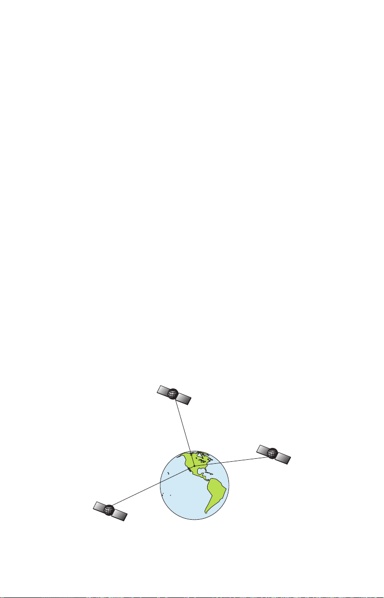
Twenty-four satellites orbit 10,900 nautical miles above the Earth, passing
overhead twice daily. a series of ground stations (with precisely surveyed
locations) controls the satellites and monitors their exact locations in the
sky. Each satellite broadcasts a low-power signal that identifies the satel-
lite and its position above the earth. Three of these satellites are spares,
unused until needed. The rest virtually guarantee that at least four satel-
lites are in view nearly anywhere on Earth at all times.
A minimum of three satellites are required to determine a 2D fix.

9
The system requires signal reception from three satellites in order to
determine a position. This is called a 2D fix. It takes four satellites to
determine both position and elevation (your height above sea level —
also called altitude). This is called a 3D fix.
Remember, the unit must have a clear view of the satellites in order to
receive their signals. Unlike radio or television signals, GPS works at
very high frequencies. These signals can be easily blocked by trees,
buildings, an automobile roof, even your body.
Like most GPS receivers, this unit doesn’t have a compass or any other
navigation aid built inside. It relies solely on the signals from the sat-
ellites to calculate a position. Speed, direction of travel, and distance
are all calculated from position information. Therefore, in order for unit
to determine direction of travel, you must be moving and the faster, the
better. This is not to say that it won’t work at walking or trolling
speeds — it will. There will simply be more "wandering" of the data
shown on the display.
GPS is plenty accurate for route navigation, but the U.S. Federal Avia-
tion Administration has special needs for aircraft traffic control that go
beyond basic GPS. The FAA has a plan under way to boost GPS per-
formance even further with its Wide Area Augmentation System, or
WAAS. This GPS add-on will include a time control element that will
help airliners fly closer together while avoiding collisions. In addition to
carefully spacing airplanes along travel corridors, WAAS will eventu-
ally make instrument landings and takeoffs more accurate as it re-
places existing aviation navigation systems.
Non-aviators can use WAAS signals to make their GPS navigation even
more accurate. Your unit receives both GPS and WAAS signals. How-
ever, WAAS has some limits you should know about.
First, the U.S. government has not completed construction of the WAAS
system, so it is not yet fully operational. The ground stations are in
place, but only a few of the needed WAAS satellites have been launched.
WAAS can boost the accuracy of land GPS navigation, but the system is
designed for aircraft. The satellites are in a fixed orbit around the
Equator, so they appear very low in the sky to someone on the ground
in North America. Aircraft and vessels on open water can get consis-
tently good WAAS reception, but terrain, foliage or even large man-made
structures frequently block the WAAS signal from ground receivers.
You'll find that using your GPS receiver is both easy and amazingly
accurate. It’s easily the most accurate method of electronic navigation

10
available to the general public today. Remember, however, that this
receiver is only a tool. Always have another method of navigation avail-
able, such as a map or chart and a compass.
Also remember that this unit will always show navigation information
in the shortest line from your present position to a waypoint, regardless
of terrain! It only calculates position, it can’t know what’s between you
and your destination, for example. It’s up to you to safely navigate
around obstacles, no matter how you’re using this product.
Free Training Aids Available
Now that you know something about the technology that makes this
unit possible, you're ready to start learning how to use that technology!
This manual will guide you through the process of setting up and run-
ning your unit, but that's only one of many resources available.
If you or a friend has Internet access, visit our web site! Find us at
www.eaglesonar.com. The site is packed with additional information on
using our products. For instance, you can learn more about interpreting
what you see on your sonar screen with our free Sonar Tutorial. The
tutorial includes animated illustrations and more pictures of actual so-
nar returns, all described in detail. There's even a "printer friendly"
version of the tutorial available on our web …it makes a great supple-
ment to this operation manual.
Sonar Viewer
You can also download a free copy of our Sonar Viewer software. This
PC-based software application plays back any sonar chart log recorded
with a Eagle sonar product. Features include:
• Adjustable range, zoom, sensitivity, ColorLine, noise rejection,
surface clarity, etc. of the recorded file.
• Color interpretation of sonar signals can be user defined.
• Operates like a Windows Multimedia Player with forward, re-
verse, pause, fast forward, fast reverse, and scroll buttons.
• Adjustments update the entire record displayed.
• Can print in full color.
• Window can dynamically be sized on your monitor.
• Mouse cursor shows GPS position, depth and sounding number
anywhere on the visible record.
Emulator
For the ultimate training aid, be sure to download the free emulator
software for your unit. Aside from being just plain fun, this program
11
can help you learn both basic and advanced operations without burning
boat fuel! Eagle is the first sonar manufacturer to provide this type of
training tool for customers.
This PC application simulates the actual sonar/GPS unit on your com-
puter. You can run it from your computer keyboard or use your mouse
to press the virtual keys. Easy download and installation instructions
are available on our web site.
Free training emulator is available for your unit on our web site.
The emulator works exactly like your real sonar/GPS unit. Using the
Sonar Simulator and GPS Simulator features, it allows you to play
back sonar logs, run GPS routes and trails, even create real waypoints
you can use in the field! You can even take snapshots of the Sonar
Chart and print them or e-mail them to friends.
And that's just some of the material available on our web site. To find
out all we have available, go to
www.eaglesonar.com and look around.
For now, though, we'll get back to how to use this particular unit. And,
first, how to use the manual.
How to use this manual: typographical conventions
Many instructions are listed as numbered steps. The keypad and arrow
"keystrokes" appear as boldface type. So, if you're in a real hurry (or
just need a reminder), you can skim the instructions and pick out what
menu command to use by finding the boldface command text. The fol-

12
lowing paragraphs explain how to interpret the text formatting for
those commands and other instructions:
Arrow Keys
The arrow keys control the movement of dotted cross-hair lines on your
mapping screen called the cursor. The arrow keys also control a hori-
zontal line depth cursor on the sonar screen. The arrow keys help you
move around the menus so you can execute different commands. They
are represented by symbols like these, which denote the down arrow
key, the up arrow, the left arrow and the right arrow: ↓ ↑ ← →.
Keyboard
The other keys perform a variety of functions. When the text refers to a
key to press, the key is shown in bold, sans serif type. For example, the
"Enter/Icons" key is shown as
ENT and the "Menu" key is shown as MENU.
Menu Commands
A menu command or a menu option will appear in small capital letters, in
a bold sans serif type like this:
ROUTE PLANNING. These indicate that you are
to select this command or option from a menu or take an action of some
kind with the menu item. Text that you may need to enter or file names
you need to select are show in italic type, such as trail name.
Instructions = Menu Sequences
Most functions you perform with the unit are described as a sequence of
key strokes and selecting menu commands. We've written them in a
condensed manner for quick and easy reading.
For example, instructions for navigating a trail would look like this:
1. From the Map Page, press
MENU|MENU|↓ to MY TRAILS|ENT.
2. Press ↓ to Trail 1|
ENT|→ to NAVIGATE|ENT.
3. You are asked to wait while it converts the trail into a route.
4. The wait message disappears and the unit begins showing
navigation information along the trail. Now, begin moving and
follow your unit's directions.
Translated into complete English, step 1 above would mean: "Start on
the Map Page. Press the Menu key twice. Next, repeatedly press (or
press and hold) the down arrow key to scroll down the menu and select
(highlight) the My Trails menu command. Finally, press the Enter key."

13
Step 2 would mean: "Press the down arrow key repeatedly to scroll to
the trail named Trail 1, and press Enter. Next, press the right arrow
key to highlight the Navigate command, then press Enter."

14
Notes

15
Section 2: Installation & Accessories
Preparations
You can install the sonar system in some other order if you prefer, but
we recommend this installation sequence:
Caution:
You should read over this entire installation section before drill-
ing any holes in your vessel!
1. Determine the approximate location for the sonar unit, so you can
plan how and where to route the cables for the transducer and power.
This will help you make sure you have enough cable length for the de-
sired configuration.
2. Determine the approximate location for the transducer and its cable
route.
3. Determine the location of your battery or other power connection,
along with the power cable route.
4. Install the transducer and route the transducer cable to the sonar
unit.
5. Route the power cable from the unit's location to an appropriate
power source and connect it there.
6. Connect the transducer/power cable to the unit and mount the sonar
unit on the bracket.
Transducer Installation
These instructions will help you install your Skimmer
transducer on a
transom, on a trolling motor or inside a hull. These instructions cover
both single- and dual-frequency Skimmer transducers. Please read all
instructions before proceeding with any installation.
Your Skimmer transducer typically comes packaged with a one-piece
stainless steel bracket for mounting it to the transom of your boat. The
optional trolling motor mount uses a one-piece plastic bracket with an
adjustable strap. These are "kick-up" mounting brackets. They help
prevent damage if the transducer strikes an object while the boat is
moving. If the transducer does "kick-up," the bracket can easily be
pushed back into place without tools.
Read these instructions carefully before attempting the installation.
Determine which of the installation methods is right for your boat.

16
Remember, the transducer location and installation is the most
critical part of a sonar installation.
Recommended Tools and Supplies
If you prefer the option of routing the cable through the transom, you
will need a 5/8" drill bit. (If you intend to install an additional speed or
temp sensor and route its cable through the same hole in the transom,
you will need a 1" (25.4 mm) drill bit to accommodate all the cables.)
NOTE:
The following installation types also call for these recommended
tools and required supplies that you must provide (supplies listed
here are not included):
Single-frequency transom installations
Tools include: two adjustable wrenches, drill, #29 (0.136") drill bit, flat-
head screwdriver. Supplies: none.
Dual-frequency transom installations
Tools: two adjustable wrenches, drill, #20 (0.161") drill bit, flat-head
screwdriver. Supplies: four, 1" long, #12 stainless steel slotted wood
screws.
Single-frequency trolling motor installations
Tools: two adjustable wrenches, flat-head screwdriver. Supplies: plastic
cable ties.
Shoot-through hull installations
Tools: these will vary depending on your hull's composition. Consult
your boat dealer or manufacturer. Other tools are a wooden craft stick
or similar tool for stirring and applying epoxy, and a paper plate or
piece of cardboard to mix the epoxy on. Supplies: rubbing alcohol, 100
grit sandpaper, specially formulated epoxy adhesive available from LEI
(see ordering information on the inside portion of the back cover). A
sandwich hull also requires polyester resin.
Selecting a Transducer Location
1. The location must be in the water at all times, at all operating speeds.
2. The transducer must be placed in a location that has a smooth flow of
water at all times. If the transducer is not placed in a smooth flow of
water, interference caused by bubbles and turbulence will show on the
sonar's display in the form of random lines or dots whenever the boat is
moving.
NOTE:
Some aluminum boats with strakes or ribs on the outside of the
hull create large amounts of turbulence at high speed. These boats
17
typically have large outboard motors capable of propelling the boat
at speeds faster than 35 mph. Typically, a good transom location on
aluminum boats is between the ribs closest to the engine.
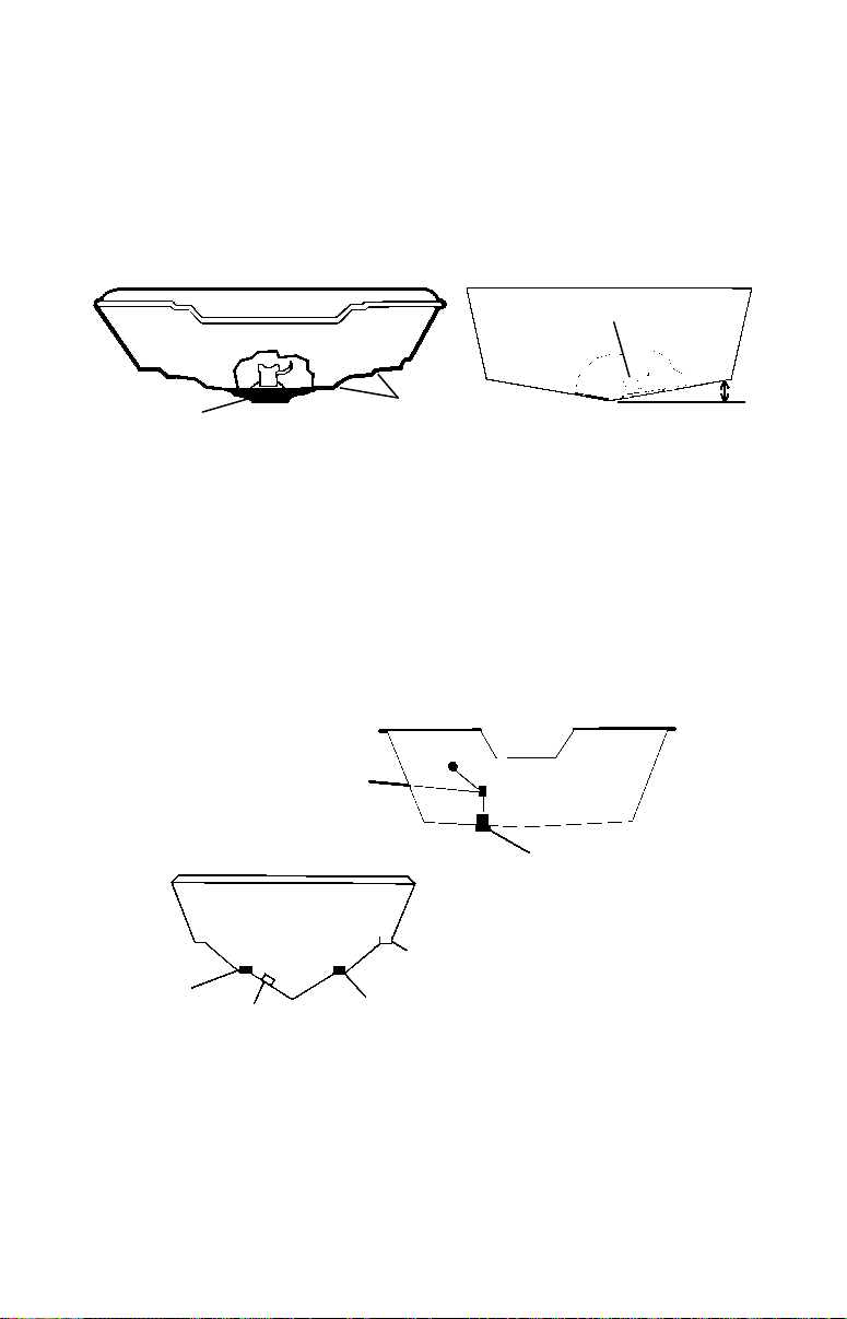
3. The transducer should be installed with its face pointing straight
down, if possible. For shoot-thru applications: Many popular fishing
boat hulls have a flat keel pad that offers a good mounting surface. On
vee hulls, try to place the transducer where the deadrise is 10° or less.
Left, vee pad hull; right, vee hull. A pod style transducer is shown
here, but the principle is the same for Skimmers inside a hull.
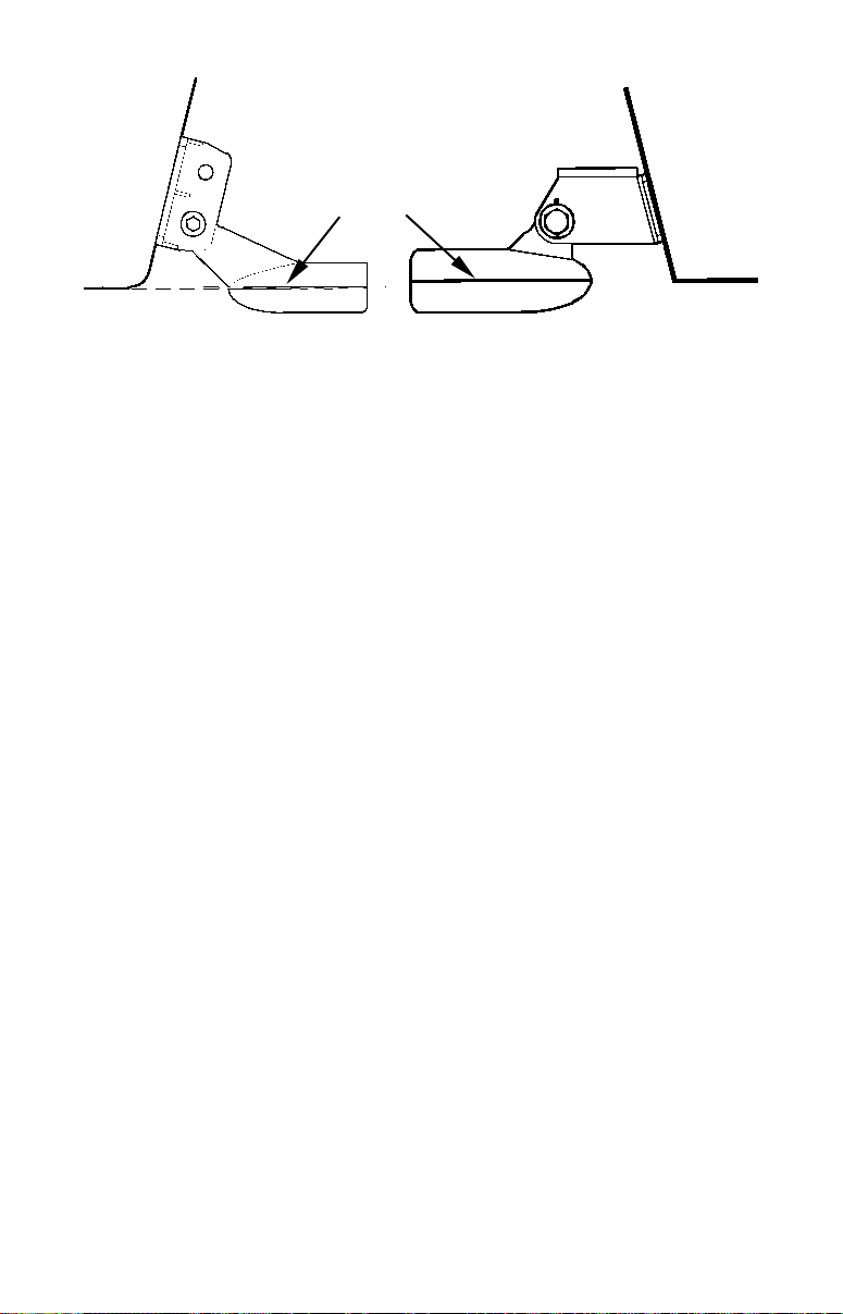
4. If the transducer is mounted on the transom, make sure it doesn't
interfere with the trailer or hauling of the boat. Also, don't mount it
closer than approximately one foot from the engine's lower unit. This
will prevent cavitation (bubble) interference with propeller operation.
5. If possible, route the transducer cable away from other wiring on the
boat. Electrical noise from engine wiring, bilge pumps and aerators can
be displayed on the sonar's screen. Use caution when routing the trans-
ducer cable around these wires.
Good and poor transducer locations.
How low should you go?
For most situations, you should install your Skimmer transducer so
that its centerline is level with the bottom of the boat hull. This will
usually give you the best combination of smooth water flow and protec-
tion from bangs and bumps.
CAUTION: Clamp the trans-
ducer cable to transom near
the transducer. This will help
prevent the transducer fro
m
entering the boat if it is
knocked off at high speed.
Good location
Good location
Poor angle
Poor location
Good
location
Deadrise less than 10°
Pad
Strakes
18
Align transducer centerline with hull bottom. A dual frequency trans-
ducer is shown at left and a single frequency transducer at right.
However, there are times when you may need to adjust the transducer
slightly higher or lower. (The slots in the mounting brackets allow you
to loosen the screws and slide the transducer up or down.) If you fre-
quently lose bottom signal lock while running at high speed, the trans-
ducer may be coming out of the water as you cross waves or wakes.
Move the transducer a little lower to help prevent this.
If you cruise or fish around lots of structure and cover, your transducer
may be frequently kicking up from object strikes. If you wish, you may
move the transducer a little higher for more protection.
There are two extremes you should avoid. Never let the edge of the
mounting bracket extend below the bottom of the hull. Never let the
bottom – the face – of the transducer rise above the bottom of the hull.
Shoot-Thru-Hull vs. Transom Mounting
In a shoot-thru-hull installation, the transducer is bonded to the inside
of the hull with epoxy. The sonar "ping" signal actually passes through
the hull and into the water. This differs from a bolt-thru-hull installa-
tion (often called simply "thru-hull"). In that case, a hole is cut in the
hull and a specially designed transducer is mounted through the hull
with a threaded shaft and nut. This puts the transducer in direct con-
tact with the water.
Typically, shoot-thru-hull installations give excellent high speed opera-
tion and good to excellent depth capability. There is no possibility of
transducer damage from floating objects, as there is with a transom-
mounted transducer. A transducer mounted inside the hull can't be
knocked off when docking or loading on a trailer.
However, the shoot-thru-hull installation does have its drawbacks.
First, some loss of sensitivity does occur, even on the best hulls. This
varies from hull to hull, even from different installations on the same
Transom
Transom
Hull bottom
Hull bottom
Transducer
centerline

19
hull. This is caused by differences in hull lay-up and construction.
Second, the transducer angle cannot be adjusted for the best fish arches
on your sonar display. (This is not an issue for flasher-style sonars.)
Lack of angle adjustment can be particularly troublesome on hulls that
sit with the bow high when at rest or at slow trolling speeds.
Third, a transducer CAN NOT shoot through wood and metal hulls.
Those hulls require either a transom mount or a thru-hull installation.
Fourth, if your Skimmer transducer has a built in temp sensor, it will
only show the temperature of the bilge, not the water surface temp.
Follow the testing procedures listed in the shoot-thru-hull installation
section at the end of this instruction booklet to determine if you can
satisfactorily shoot through the hull.
Transom Transducer Assembly and Mounting
The best way to install these transducers is to loosely assemble all of
the parts first, place the transducer's bracket against the transom and
see if you can move the transducer so that it's parallel with the ground.
The following instructions sometimes vary depending on the mounting
bracket that came with your transducer. Single frequency Skimmers
come with a one-piece stainless steel bracket, while dual frequency
Skimmers come with a two-piece plastic mounting bracket. Use the set
of instructions that fits your model.
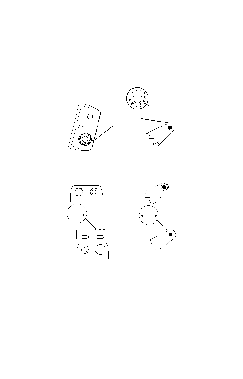
1. Assembling the bracket.
A. One-piece bracket: Press the two small plastic ratchets into the sides
of the metal bracket as shown in the following illustration. Notice there are
letters molded into each ratchet. Place each ratchet into the bracket with
the letter "A" aligned with the dot stamped into the metal bracket. This
position sets the transducer's coarse angle adjustment for a 14° transom.
Most outboard and stern-drive transoms have a 14° angle.
Align plastic ratchets in bracket.
B. Two-piece bracket: Locate the four plastic ratchets in the trans-
ducer's hardware package. Press two ratchets into the sides of the plastic
Dot
20
bracket and two on either side of the transducer as shown in the follow-
ing illustrations. Notice there are letters molded into each ratchet. Place
the ratchets into the bracket with the letter "A" aligned with the align-
ment mark molded into the bracket. Place the ratchets onto the trans-
ducer with the letter "A" aligned with the 12 o'clock position on the
transducer stem. These positions set the transducer's coarse angle ad-
justment for a 14° transom. Most outboard and stern-drive transoms
have a 14° angle.
Insert and align ratchets.
Add ratchets to bracket and transducer.
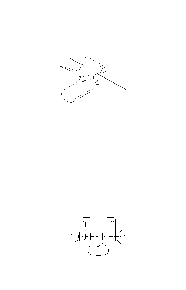
2. Aligning the transducer on the transom.
A. One-piece bracket: Slide the transducer between the two ratch-
ets. Temporarily slide the bolt though the transducer assembly and
hold it against the transom. Looking at the transducer from the side,
check to see if it will adjust so that its face is parallel to the ground.
If it does, then the "A" position is correct for your hull.
If the transducer's face isn't parallel with the ground, remove the
transducer and ratchets from the bracket. Place the ratchets into the
holes in the bracket with the letter "B" aligned with the dot stamped
Alignment letters
Alignment
positions
Transducer bracket
Transducer
Transducer
bracket
Ratchet
Ratchet
Transducer
21
in the bracket.
Reassemble the transducer and bracket and place them against the
transom. Again, check to see if you can move the transducer so it's par-
allel with the ground. If you can, then go to step 3A. If it doesn't, repeat
step 2A, but use a different alignment letter until you can place the
transducer on the transom correctly.
Insert bolt and check transducer position on transom.
B. Two-piece bracket: Assemble the transducer and bracket as
shown in the following figure. Temporarily slide the bolt though the
transducer assembly but don't tighten the nut at this time. Hold the
assembled transducer and bracket against the transom. Looking at the
transducer from the side, check to see if it will adjust so that its face is
parallel to the ground. If it does, then the "A" positions are correct for
your hull.
If the transducer's face isn't parallel with the ground, remove and
disassemble the transducer and ratchets. Place the ratchets into the
bracket holes with the letter "B" aligned with the bracket alignment
mark. Place them on the transducer aligned with the 12 o'clock posi-
tion on the transducer stem.
Reassemble the transducer and bracket and place them against the
transom. Again, check to see if you can move the transducer so it's
parallel with the ground. If you can, then go to step 3B. If it doesn't,
repeat step 2B, but use a different alignment letter until you can
place the transducer on the transom correctly.
Assemble transducer and bracket.
Ratchets
Flat washer
Lock washer
Flat washer
Nut
Bolt
22
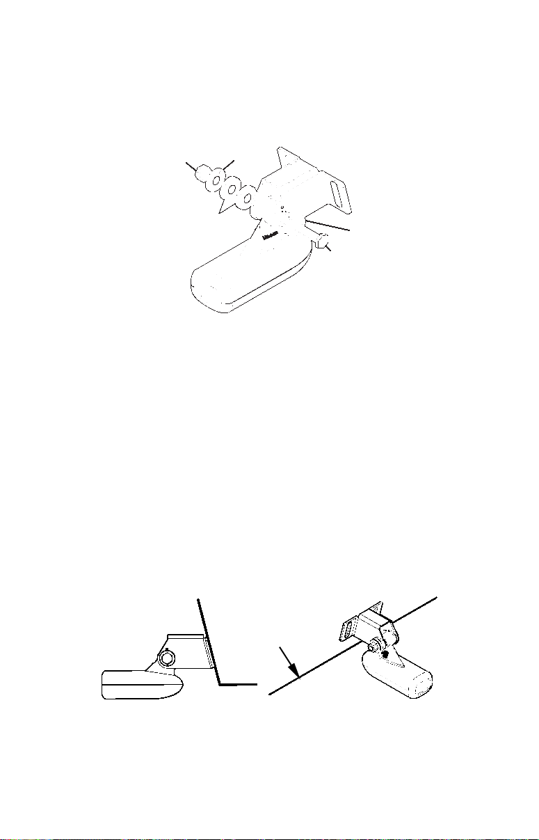
3. Assembling the transducer.
A. One-piece bracket: Once you determine the correct position for the
ratchets, assemble the transducer as shown in the following figure.
Don't tighten the lock nut at this time.
Assemble transducer and bracket.
B. Two-piece bracket: Once you determine the correct position for the
ratchets, assemble the transducer as shown in the figure in step 2B.
Don't tighten the lock nut at this time.
4. Drilling mounting holes.
Hold the transducer and bracket assembly against the transom. The
transducer should be roughly parallel to the ground. The trans-
ducer's centerline should be in line with the bottom of the hull. Don't
let the bracket extend below the hull!
Mark the center of each slot for the mounting screw pilot holes. You
will drill one hole in the center of each slot.
Drill the holes. For the one-piece bracket, use the #29 bit (for the #10
screws). For the two-piece bracket, use the #20 bit (for the #12
screws).
Position transducer mount on transom and mark mounting holes.
Side view shown at left and seen from above at right.
5. Attaching transducer to transom.
Nut
Metal
washer
Metal washer
Bolt
Rubber
washers
Transom
Transom
 Loading...