

Page 1

HOW TO OBTAIN
Electronics will
Eagle
Eagle parts
write us at the address below before
to save
do have to return the unit for
problem
testing
you
that
and
should
the
inconvenience of
you
repair
provide quek
ever
you
are
of
your depth
Mail to: EAGLE ELECTRONICS
having
require
sending
service,
with the unit. This will assist us in the
sounder.
P0. BOX 669
CATOOSA,
If
If
Should
sounder,
promptly
EAGLE.
live out of the state of
you
live in the state of
you
Oklahoma,
Oklahoma,
SCHEMATIC DIAGRAM & PARTS LIST
desire a schematic and
you
send
Please be sure and
to the address above
$1.00
give
us the model and serial
SERVICE
and efficient service
it. If
sending
please
call collect 918-266-5373.
parts
do
you
require service,
in the unit. We
the unit back for
enclose a letter
OKLAHOMA 74015
call 1-800-331-2301.
list for
and
your
it will be
with
repairs.
EAGLE
mailed to
number of
genuine
call or
be able
may
stating
If
you
the
depth
you
your
41
EAGLE
MODEL SILENT
SIX/SIXTY
INSTALLATION INSTRUCTIONS
EAGLE ELECTRONICS
LImO IN U.S.A.
9 66-0087-01
- -
EQ. BOX
A DiviiOh Ol
I
Lcwrance Electronics Inc
669, CATOOSA,
OKLA. 74015
PDF compression, OCR, web-optimization with CVISION's PdfCompressor
Page 2
INTRODUCTION
Thank
proof
believe that it is the finest unit
available
right
sion
tolerances.
lb
fully enjoy
this
equipment
suggest
ual
thoroughly
tempt
this
product.
Please fill out the
and mail it to EAGLE ELEC-
TRONICS. This will
your
We
suggest
original
was
shipped in,
needs to be returned to the fac-
for
tory
tainer will be available.
for
you
EAGLE
here in
that
selecting
depth
manufactured
today,
the U.S.A. to
the
advantages
brings
read this man-
you
before
sounder. We
to
any
at installation or use
warranty
1
year
FULL
that
carton that the EAGLE
repairs,
register
warranty.
you keep
so that if it
a suitable con-
a water-
preci-
you,
at-
of
card
the
ever
POWER CONNECTIONS
Power for the
supplied by
electrical
picked up
power buss,
lems with electrical
which is indicated
flashes on the
we
minimized
directly
Figure
If a
quired,
cable available at
system.
to the
1.)
longer power
use
or electrical
should be soldered. If this can't
be
Simple twisting
done,
use
result in intermittent
connections which can cause in-
terference.
electrical
tape.
SPECIFICATIONS
Dimensions with knobs and
Dial 0-60
Voltage
Current
Drain 250
gimbals
Pulse Width 200-1000
Output
Power 200 watts
. 711 x 8W x 61)
(outer),
12 volts D.C.
volts)
ma.,
(typical)
25 wafts RMS
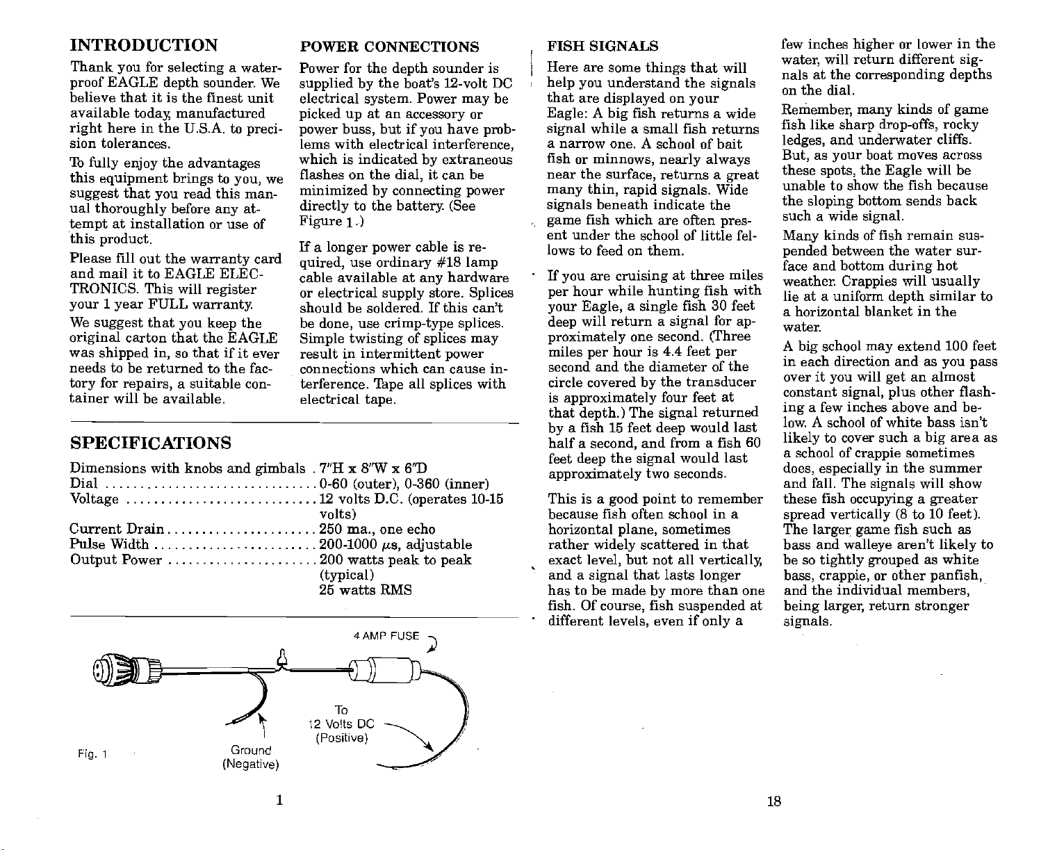
4AMP FUSE
sounder is
depth
the boat's 12-volt DC
at an
but if
dial,
Power
accessory
may
or
have
you
interference,
extraneous
by
it can be
prob-
by connecting power
battery
ordinary
supply
crimp-type splices.
'Ihpe
0-360
one echo
cs,
adjustable
peak
(See
cable is re-
#18
hardware
any
store.
of
splices may
power
all
splices
(inner)
(operates
to
peak
lamp
Splices
with
10-15
be
FISH SIGNALS
Here are some
help you
that are
Eagle:
signal
a
fish
near the
many thin, rapid
signals
game
ent under
lows
If
per
your Eagle, a single
deep
proximately
miles
second and the diameter of the
circle covered
is
that
by
half a
feet
approximately
This is a
because fish often school in a
horizontal
rather
exact
and a
A
while a small fish returns
narrow one. A school of bait
or
minnows,
beneath
fish which are often
to feed on them.
are
you
hour while
will return
per
approximately
depth.)
a fish 15 feet
second,
deep
widely
level,
signal
things
understand the
displayed
fish returns a wide
big
surface,
the school of little fel-
cruising
hunting
one second.
hour is 4.4 feet
by
The
and from a fish 60
the
signal
two seconds.
good point
plane,
scattered in that
but not all
that lasts
has to be made
fish. Of
different
course,
levels,
that will
signals
on
your
nearly always
returns a
signals.
indicate the
at
great
Wide
pres-
three miles
fish with
fish 30 feet
a
signal
for
(Three
per
the transducer
four feet at
signal
deep
by
fish
even if
returned
would
would
last
to remember
sometimes
vertically,
longer
more than one
suspended
only
last
a
ap-
few inches
water,
nals at the
on the dial.
Remember, many
fish like
ledges,
But,
these
unable to show the fish because
the
sloping
such a wide
Many
pended
face and bottom
weather.
higher
will return different
corresponding depths
sharp drop-offs, rocky
and underwater cliffs.
as
your
spots,
kinds of fish remain sus-
between the water sur-
Crappies
lie at a uniform
or lower in the
kinds of
boat moves across
the
Eagle
bottom sends back
signal.
during
will
depth
a horizontal blanket in the
water.
A
school
big
in each direction and as
over it
constant
ing
low. A school of white bass isn't
likely
a school of
does,
you
signal, plus
a few inches above and be-
to cover such a
crappie
especially
and fall. The
these fish
spread vertically
The
bass and
be so
bass,
occupying
larger game
walleye
tightly grouped
crappie,
and the individual
at
being larger,
signals.
extend 100 feet
may
will
an almost
get
sometimes
in the summer
signals
a
to 10
(8
fish such as
aren't
or other
members,
return
stronger
sig-
game
will be
hot
usually
similar to
you pass
other flash-
area as
big
will show
greater
feet).
to
likely
as white
panfish,
To
12 Volts DC
(Positive)
1 18
Fig.
1
Ground
(Negative)
PDF compression, OCR, web-optimization with CVISION's PdfCompressor
Page 3
TREES IN THE WATER
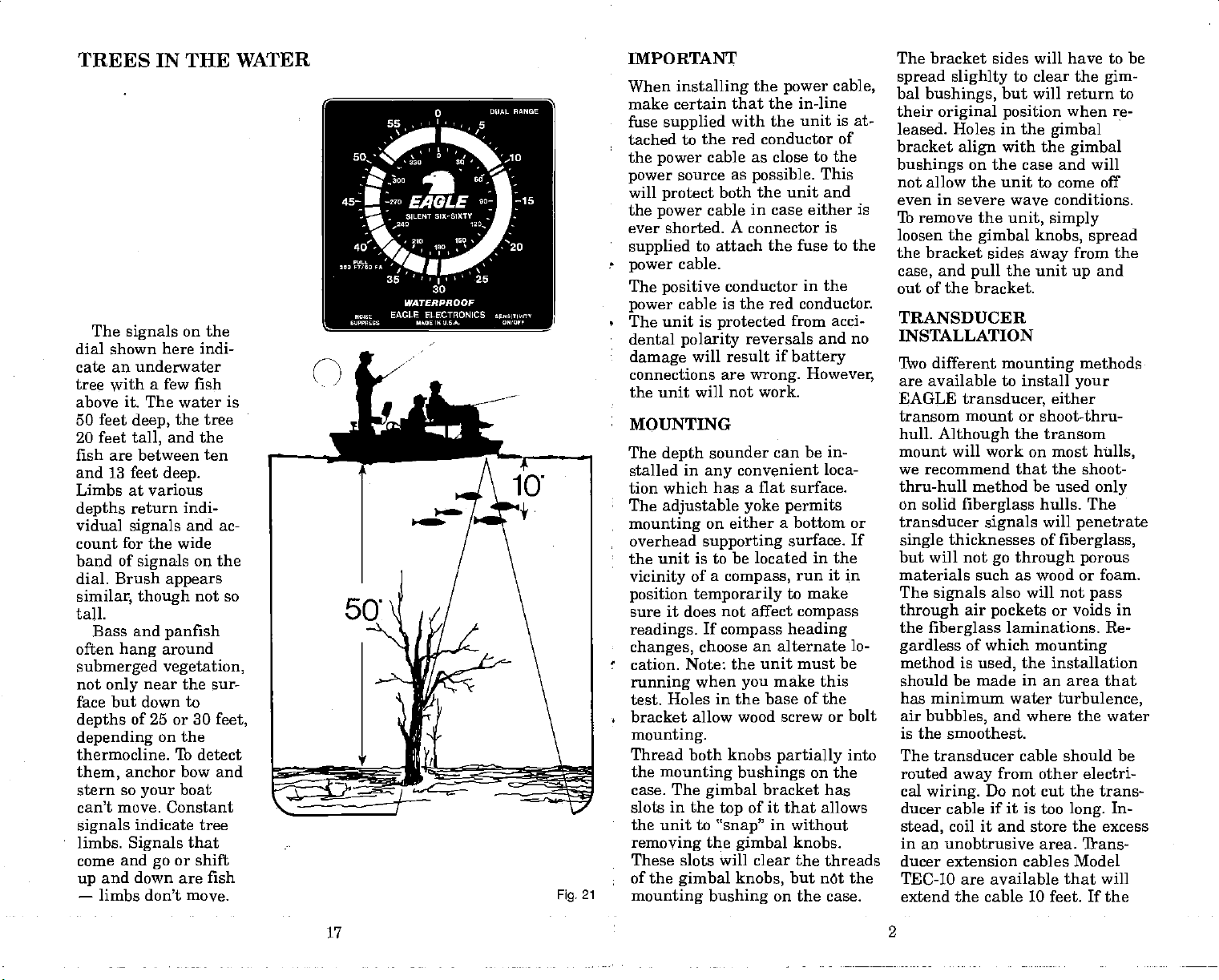
The
signals
dial shown here indi-
cate an underwater
tree
with
above it. The water is
50 feet
20 feet
deep,
tall,
fish are between ten
and 13 feet
Limbs at various
depths
vidual
count for the wide
band of
dial. Brush
similar, though
return indi-
signals
tall.
Bass and
often
hang
submerged vegetation,
not
only
face but down to
depths
depending
thermocline. To detect
them,
of 25 or 30
anchor bow and
stern so
move.
can't
signals
limbs.
come and
up
—
Signals
and down are fish
limbs don't move.
on the
a few fish
the tree
and the
deep.
and ac-
signals
near the sur-
your
indicate tree
on the
appears
not so
panfish
around
on the
boat
Constant
that
or shift
go
feet,
Fig.
IMPORTANT
When
installing
make certain that the in-line
fuse
supplied
tached to the red conductor of
the
power
power
will
the
ever shorted. A connector is
•
-
The
•
•
source as
protect
power
supplied
cable.
power
positive
cable is the red conductor.
power
The unit is
dental
damage
connections are
polarity
with the unit is at-
as close to the
cable
possible.
both the unit and
in case either is
cable
to attach the fuse
conductor
protected
reversals and no
will result if
wrong.
the unit will not work.
MOUNTING
21
The
stalled
tion which has a
The
mounting
overhead
the unit is
vicinity
position temporarily
sure it does not
readings.
•
changes,
cation. Note:
running
test. Holes
bracket allow wood screw or bolt
mounting.
Thread both knobs
the
mounting bushings
case. The
slots
•
the unit to
removing
These slots will clear the threads
of the
mounting bushing
sounder
depth
in
adjustable
convenient loca-
any
on either
supporting
to be located in the
of a
compass,
If
compass
choose
the unit must be
when
you
in the base of the
gimbal
in
the
top
"snap"
the
gimbal
gimbal knobs,
yoke permits
affect
of it that allows
the
power
cable,
This
to the
in the
acci-
from
battery
However,
can be in-
flat surface.
a bottom or
surface. If
run it in
to make
compass
heading
an alternate lo-
make this
partially
into
on the
bracket has
in without
knobs.
but net the
on the case.
The bracket sides will have to be
spread slighlty
bal
bushings,
their
original position
leased. Holes in the
bracket
bushings
align
to clear the
gim-
but will return to
when re-
with the
on the case and will
gimbal
gimbal
not allow the unit to come ofT
even in severe wave conditions.
lb remove the
loosen the
the bracket sides
and
case,
unit, simply
gimbal knobs, spread
the unit
pull
away
from the
and
up
out of the bracket.
TRANSDUCER
INSTALLATION
Two different
mounting
are available to install
EAGLE
transom mount or shoot-thru-
hull.
mount will work on most
we recommend that the shoot-
transducer,
Although
the transom
thru-hull method be used
on solid
transducer
single
but will not
fiberglass
signals
thicknesses of
go through porous
methods
your
either
hulls,
hulls. The
will
only
penetrate
fiberglass,
materials such as wood or foam.
The
signals
through
the
fiberglass
gardless
method is
should be made in an area that
has minimum water
air
bubbles,
also will not
air
pockets
of which
used,
or voids
laminations. Re-
mounting
the installation
turbulence,
and where the water
pass
in
is the smoothest.
The transducer cable should be
routed
cal
wiring.
ducer cable if
coil it and
stead,
from other electri-
away
Do not cut the trans-
it
is too
long.
store the excess
In-
in an unobtrusive area. 'frans-
ducer extension cables Model
TEC-10 are available that will
extend
the cable 10 feet. If the
17
2
PDF compression, OCR, web-optimization with CVISION's PdfCompressor
Page 4

transducer cable needs to be ex-
tended
depth
will need to be
factory
Fig.
longer
sounder
for
2
than 10
feet,
and transducer
returned to the
re-alignment.
the
SIGNALS RETURNED BY A ROCKY BOTTOM
XD-2
1vo other transducers are
able for
sounder. Model XD-2 is a
speed plastic
EAGLE
your
unit that can be
avail-
depth
high
transom mounted or can shoot-
thru-hull. It works well on
vee hulls and aluminum boats.
The other transducer
3
Fig.
XD-3
special
it below
layer
is for
trolling
or shoot-thru-hull.
Ji
bracket
transducer that will
the severe cavita-
that is sometimes
on
aluminum boats. The
XD-3)
mounting
A
the XD-2
put
tion
present
model number for
XMB-2.
motor
is available
this bracket
deep
(Model
SHOOTING THROUGH
HULL
1.
Mounting
recommended for
inside the hull
hulls in an area that
have air bubbles in the resin
or
separated fiberglass layers.
The sonar
through
successful transducer installa-
solid
tion can be made on hulls
that have flotation materials
(such as wood or
tween
layers
the material is removed from
the
chosen area. For
for
is
some
manufacturers use a
of
layer
of balsa
outer
removing
fiberglass
core,
fiberglass,
wood,
layer
the inner
and the balsa wood
the
outer
fiberglass
signal
must
fiberglass.
foam)
of
fiberglass
and
of
fiberglass. By
layer
THE
is
does not
pass
A
in be-
if
example,
then a core
then the
of
layer
of
Fig.
20
The
from a
are
when
them.
signals
rocky
quite
you
The EAGLE's
dial will indicate
level of the bottom at
the correct
it will also show
thin
signals
below the wider main
bottom
explained by
signal.
returned
bottom
confusing
first see
the
depth,
but
clear
above and
This is
the fact
that the rocks near the
outer
of sound waves are
farther from the
transducer than those
in
the
the
tops
are closer than the
bottom.
This
shows
nals
school of
bluegills
twenty
nals are
those returned
fish.
of the cone
edge
center,
of the latter
drawing
the
typical sig-
indicating
white bass or
at a
depth
feet.
The
brighter
while
also
a
sig-
than
by
of
bait
3 16
PDF compression, OCR, web-optimization with CVISION's PdfCompressor
Page 5

WIDTH OF SIGNAL INDICATES SIZE OF FISH
Small minnows or
bait fish
dial as
If
they
schooled
cover a
five to ten feet on the
appear
thin,
are
they may
depth
dial with a few
lines for individual.
minnows at the bottom
of the school. Your
EAGLE
even a
30
surface of the water.
of a
larger
flect the
will
single
feet beneath
Obviously,
fish offers a
big
surface to re-
signal
the back of a small
fish.
Consequently, yop
a wider and
get
brighter signal
dial
you
size of the fish from
the
you a good
you
big
ones.
even
and,
can't tell the exact
signal,
can
instantly
ones from little
on the
lines.
pale
tightly
of from
pale
indicate
minnow
the
the back
than
on the
though
it does
clue so that
give
tell
Fig.
19
fiberglass
exposed.
then be
epoxied
this outer
When
5.)
and
The transducer can
layer.
epoxy
coat
gel
directly
(See
is
poured
Figure
the hole and the transducer
placed
is still
no weak
2. The chosen area should be in
into the
structurally rigid
points
the hull
epoxy,
are made.
the aft one-third of the hull
on
planing
of the
intakes in
Water should flow
boats,
engines
displacement
and forward
and/or water
smoothly
in this area and it should
in the water at all
4
3. Before
the transducer to the
permanently bonding
speeds.
hull,
trial runs are recommended
to find the best
cation. Once an area has been
determined to be a
for the transducer to be
mounted,
the
area,
ducer in it face down. This
will eliminate air between
mounting
good spot
add some water to
and
place
the trans-
are
to
into
and
hulls.
face of the transducer and the
hull.
the unit and turn the
sounder
all
at
transducer until the best loca-
tion is
signal
minimum cavitation noise
(cavitation
turbulence and shows
narrow
sonar dial.)
4. If the chosen area
potential
stay
surface
face of the transducer with
100
grit sandpaper.
face must be flat
that the entire transducer
lo-
the
face is in contact with the
hull
Build
5.
caulking compound
ing clay
area of
not use PLAY-DOll) (See
Figure
transducer
the
Plug
on.
Operate
speeds
and move the
found for maximum
reception
is caused
signals
problems,
of the hull and the
to
prior
bonding.
depth
the boat
and
by
all around the
void of
is
sand the
The sur-
enough
a small dam out of
or model-
around the chosen
the
transducer. (Do
7.)
water
up
into
as
so
PDF compression, OCR, web-optimization with CVISION's PdfCompressor
15
4
Page 6

Fig.
7
and bubbles.
or transducer should not in-
Also,
the
bracket
SIGNALS
FROM
STEEP,
ROCKY LEDGES
terfere with the boat trailer
or
hauling
3.
1'ypically,
should be located
of the boat.
the transducer
half-way
be-
tween the center of the
transom and the outside
of the hull.
(See
Figure
edge
8.)
6. Use a
epoxy
good quality two-part
to bond the
transducer
to the hull. Do not use
silicone rubber sealer or
adhesive that does not
rock hard. Follow the instruc-
tions on
and mix
a
small amount on the entire
face of the transducer and
pour
area
dam. Place the transducer
into the
turning
bubbles out
the
epoxy package
it
thoroughly.. Apply
1/16" thick level into the
contained
epoxy
by
by
pushing
to force all of the air
from under the
the
any
get
clay
and
transducer face. The trans-
ducer face should be
with the boat
minimum amount of
between hull and
Weight
until the
7. Route the transducer cable
hull,
the transducer
epoxy
along gunwales
from
power
TRANSOM MOUNT
1.
Loosely
cables.
attach the brackets to
parallel
with a
epoxy
transducer.
down
cures.
and
away
the transducer with the
hardware
2. Locate the bracket where the
flow of water is smoothest
provided.
with minimum turbulence
The transducer should be
mounted
or other hull
ribs,
that
can cause turbulence.
4. If
the hull deadrise exceeds 4
degrees,
mount on the centerline of
the hull or an
ducer should be used.
Figure
9
Fig.
5. Place the bracket
a shoot-thru-hull
9.)
away
from
stakes,
fittings
optiQnal
against
(See
transom in the selected area
with the bottom of the trans-
ducer flush with the bottom of
the hull.
Alignthe
transducer
with the bottom of the boat
hull
by
Mark
using a straight edge.
the transom for
drilling
-
trans-
the
Fig.
18
Your EAGLE trans-
lates time into dis-
tance — the farther
the sound waves
the
longer
go,
it takes
them to return to the
transducer and the
greater
shown on the dial.
Nowhere is this shown
more
when
over a
underwater
cliff;
inclined at a
the cliff is
the
depth
boat
steep,
than
rocky
ledge
clearly
your
either vertical or
Assume the
steep angle.
top
15 feet be-
passes
or
of
neath the surface of
the
water,
tom is 50 feet
Sound waves will
rough spots
all the
the
result,
and the bot-
on the cliff
down. As
way
the
deep.
hit
signals
on the dial will cover
an area
from
condition that could
easily
sion until
extending
15 to 50 feet — a
lead to confu-
under-
you
stand it.
5 14
PDF compression, OCR, web-optimization with CVISION's PdfCompressor
Page 7

MUD BOTTOM CAUSES
When
ing fish,
adjusted properly
return a
signal
of
gravel, sand,
shell, you
times see the
disappear.
mean that
suddenly
tremely deep
the dial would have
shown the
with a wide band of
signals
Instead,
now above a mud bot-
tom. Mud absorbs the
sound waves. Thrn
the
gain.
signal may
from a bottom of de-
caying vegetation
under
will still show on the
however. Back
dial,
over a hard
you'll get multiple
signals.
are hunt-
you
with the
clear, bright
from a bottom
will some-
This doesn't
you
come to ex-
gain
to
or
signal
have
water
drop-off
in this case.
boat is
your
up
The bottom
be faint
water. Fish
deep
bottom,
—
Mud and
THE SIGNAL TO FADE
decayed vegetation
Fig.
17
the
mounting
of the slots
6. Mount
the
holes at the
in the bracket.
assembly
transom with two #10 screws.
the face of the trans-
Align
ducer with
hull with a
Tighten
7. Route the
the
depth
the bottom of the
straight edge.
all screws.
transducer cable to
sounder unit. Do
not cut the transducer cable.
If it is too
excess in an out-of-the-
the
location.
way
S. Make a
test run to determine
coil and store
long,
the results. Some boat hulls
require lowering
of the transducer 2° to
edge
6°. If the run was
drill
•
bottom of the slots and install
two
The transducer must be
•
against
results. After
fill
transom and the transducer
with
epoxy,
more holes in the
two
more #10 screws. Note:
the transom for
voids between the
any
caulking compound,
silicone adhesive.
or
the back
satisfactory,
locking
OPERATION
SENSITIVITY
"ON-OFF" KNOB
This knob
similar to the volume control
AND
operates
in a manner
to the
good
in
place,
top
on
a radio.
clockwise will
and
full counterclockwise
will turn the unit off.
the knob
clockwise manner will increase
Thrning
turning
in a continued
the receiver
weaker echos from
can and will be observed on the
dial. After
turn the unit on
ducer,
the
ing
clockwise. You will see the con-
sensitivity
stant surface
fore
long, you
—
signal
is ten feet
cates the bottom.
always
Continue
control toward the
will see
at ten feet if the water
show.
turning
a second bottom
at double the
20 feet. The sound waves have
or
hit
bottom,
surface
bounced
Over a firm bottom
crease
of the
down and
the
the knob
turn the unit
the knob
sensitivity
deeper
mounting
signal
will see another
deep.
the trans-
knob
at zero. Be-
This
It, too,
the
right
of the
depth
bounced
sensitivity
water,
up again.
back,
then
you
on,
back the
position
Thrning
and
water
turn-
by
signal
indi-
should
Sensitivity
and
you
signal
first,
hit the
can in-
until the
dial shows three or four bottom
signals
depth.
The
sensitivity
should
you
turn a
nearly
—
nal
at
multiples
always
steady
as
bright
regardless
of true
is
adjustable
set it to re-
bottom
as the zero
of
depth.
signal
and
—
sig-
'Ilirn
the knob counterclockwise when
to
you begin
tom
signal;
bottom
show
should be set to show a
bright
fishermen
sitivity
signal begins
fish the
bottom
control
the second bottom
the double bot-
get
clockwise when the
to fade. lb
strong,
signal
control
with
show-
sensitivity
signal. Many
prefer
to run the sen-
very high
PDF compression, OCR, web-optimization with CVISION's PdfCompressor
13
6
Page 8

to insure
ing
the
underwater detail as well
fish.
NOISE
CONTROL
The noise
can be used
eliminate false
dial. These false
caused
from the boat's motor
bubbles
that
SUPPRESS
suppress
to cut down or
flashes on the
flashes can be
by ignition
passing
over the face of
they
control knob
interference
or
the transducet
Ilirning
the knob
creass the
press.
Always
suppress
increase in it cuts down
ability
rate
fish) close
Increasing
as
of the unit to show
signals
together.
noise
clockwise in-
amount of noise
use as
possible,
or
because an
objects
suppress
little noise
(such as
flfl)))flfl)flflfl)))fl
.( ((((
SIGNAL SENT BY LOCATOR BOUNCES
TARGET. TIME LAPSE INDICATES
11
Fig.
not affect the
unit.
RANGE
The
range
select either
0-60
fathom
Noise
Suppress
used to
pulling
fathom
pushing
scale to the 60'
sensitivity
control is used
the 0-60' or the
scale.
(360')
control knob
change
the
range
the
the scales.
knob
is
knob in switches the
the 0-60
out,
selected,
range.
see all
control in the 60'
as
range
outside 0-60 scale. With
control in the 60 fathom
position,
in fathoms on the outside
scale,
the
faceplate.
HOW
by
air
EAGLE DEPTH
SOUNIJER
The
ation of
sup-
Ranging.
ing
on the
sepa-
tracking
Sound travels at
4,800
water
mately 1,100
does
PRINCIPLE OF SONAR
((((
of the
to
The
is
By
through
( ((
(((
(
The
simplest
pulse
wave
transmitted into the water.
When this wave
ject,
of sound
known,
the transmitted
and
With the
received echo can be measured
and the distance to the
determined.
should be read on the
the
or
may
inside 0-360' scale on
position,
range may
be read in feet
the
the
be read
0-60
on
the
TO USE YOUR
word 'Sonar" is an abbrevi-
Sound,
World War II
enemy
feet
as
air.
( ( ((((((K
a sonar works in its
way
form is an
Navigation,
It
was
developed
as a means of
submarines.
approximately
second
per
compared
feet
DISTANCE TO TARGET
through
to
second
per
BACK FROM
electrical
is converted into a sound
the transducer and
by
strikes
it rebounds. Since the
through
the time
water is
lapse
signal
and
dur-
approxi-
an
ob-
speed
between
and the
object
HARD
Sand
bottom
16
Fig.
CLAY, SAND,
GRAVEL,
SHELL
BOTTOMS
Some
fish,
bass, catfish, walleyes,
and
crappies,
sionally
lie
the bottom. Even here
the EAGLE will show
them
as
you pass over,
provided
smooth
gravel.
shows a
with the
control
that a
signal
the bottom is
sand,
Figure
hard bottom
sensitivity
adjusted
strong
is
displayed
with two fish at 20
and 21 feet. A second
echo
that
as
the actual bottom
signal
sitivity
turned
to see
This is
the sound
flecting
tom,
be
may
is twice as
when the sen-
control is
up high enough
fish.
caused
waves re-
from the bot-
bounce
the water's
turn to the
reflect back to the
sonar unit.
fishermen
run
control
the
second bottom
nal
showing
that
underwater
well as fish.
The second
shown at 50 feet in
figure
the
sensitivity
very high
see all the
they
16.
prefer
including
occa-
on
right
or
shell,
16
so
bottom
displayed
deep
by
back from
surface,
bottom and
Many
re-
to
with
sig-
to insure
details as
echo is
7
12
PDF compression, OCR, web-optimization with CVISION's PdfCompressor
Page 9

WEAK SIGNAL INDICATES GAIN TOO LOW
Fig.
12
Fish: 17 ft.
D,pth:
35
$
I
ak
t t
wArgRpIlOOF
EAGLE ELECThONOGG,,!G,!,.
EAGLE
"U:
The
trol on
might
sensitivity
your
be
compared
con-
EAGLE
to
the volume on a radio.
Thrn the
knob to the
you
ceiver
it to the left and
reduce it. This feature
is
provided
can use
over both
shallow water and
should
the
bright
shows on the
gardless
you
have
tom
will fail to show fish
sensitivity
increase the re-
sensitivity;
your
deep
always adjust
so that a
gain
bottom
of
fail to do so and
a faint bot-
only
signal
and
right
you
so that
EAGLE
and
signal
dial,
depth.
the dial
turn
Jf
you
you
re-
in the water between
the transducer and the
bottom. This condition
is shown in the draw-
above — the
ing
are there but
aren't shown on the
dial because the
fish
they
gain
is set too low.
Fig.
15
The
Eagle depth
mits a
wave
as well as humans)
high
(which
sounder
frequency
inaudible to fish
is
watet At the same
intensity
constant
on a disc driven
governed
lighted every
ter fires. This
reference
is used as a
measure
cator that
on. Even
flashes,
the human
nearly
The bulb
point
the
by
sound waves
and
returned from
water
bottom fire the
these
show the exact
—
neon bulb whirls
behind
speed
by
motor. The bulb
time the transmit-
provides
on
point
starting point
depth,
it
constant
the dial that indicates
on
depth.
the
length
and as
the
depth
eye
The
the neon bulb
sees
light.
point
though
happens
also flashes at the
of time it takes the
to reach the bottom
return. In
addition,
any object
between the surface and
echoes are also
or
any
bulb,
depth
number of fish
the dial which
trans-
sound
through
time, a high
the
at a
the dial
an
accurately
is
visual
a
to
an indi-
sounder is
so often that
it
a
as
is indicated
echoes
in the
too. Since
timed, they
of
any
—
fish
in
the water. And because the
sound waves from the transducer
down into the
go
row cone
angle,
a matter of a few
location as well as the
At a
depth
covers a circle that
mately
15 feet it is two feet
feet,
diameter is four feet wide.
gardless
sound ends at the bottom.
one foot
three feet
of
an echo is also returned
any object
ducer and the bottom.
water in a nar-
they tell,
feet,
of 10
feet,
in
diameter;
wide,
depth,
between
the cone of
the fish's
depth.
the cone
is
approxi-
wide,
the cone
from
the trans-
within
at
at 20
Re-
But
PDF compression, OCR, web-optimization with CVISION's PdfCompressor
11
8
Page 10

As
a
will
dial until it
dial is calibrated to a
feet,
Continue
signal
Add
60 to
inside dial on the
Silent
60
depths
Other
ranges
to a
deeper
SIGNAL INTERPRETATION
Because
tremely
it can
move
you
deep lake,
gradually
away
the
bottom
move around
reaches zero. If the
the water is 60 feet
further,
will start around
whatever
get
Sixty
120
to
greater
Eagle
figure
the correct
1 is calibrated from
feet to
help you
than 60 feet.
models have dual
that allow
deeper
scale when
than 60
your Eagle
sensitive and
give you
feet.
an accurate
from
shore on
signal
depth
deep.
and the
again.
it shows to
depth.
Model
Eagle
to
you
change
you go
is both ex-
powerful,
the
of
bottom
The
read
pic-
ture of the kind of bottom over
which
bottom of firm
shell,
bright, fairly
are
traveling
and the
means
a soft mud bottom. A
absorbs the
turns a weak
simply
a
get
A level
rocks returns the usual
signal
both above and below it.
caused
the sound waves travel.
that
go straight down,
and come back
rectly,
above the level of the bottom.
But the sound waves that hit
boat is
your
or hard
signal
that
you
sound waves and re-
turn
up
bottom
good
bottom with scattered
—
plus secondary
the different
by
passing.
sand,
gravel,
returns a
clay
wide
signal.
over such a bottom
weakens,
have moved over
soft bottom
In
signal.
the
this
sensitivity
reading.
bottom
distances
Those
hit a
cor-
of the rock
that the
indicate,
top
A
If
you
it
case,
signals
This is
rock,
a
rock toward the outer
cone of sound waves and
flected back to the transducer
travel further.
60
their
signals appear
tottom
signal.
A smooth bottom of solid rock
returns a
Broken rock of various sizes
sends back an even wider
with occasional flashes above
and below
bottom, though
aren't so
turned
smooth
Big
bottom send back
distinct as the ones re-
by
botto,m.
rocks or
the level of a smooth
distance
height.
proach
you
climb
side
A
steep slope
nal,
the
underwater cliff
widest. The sure
drop-off
the
wide
to
width,
or
deeper
depending
If
you
a
post
will
often see the
then descend the other
up,
as
you
the
steeper
signal
is the sudden
regular depth signal
then back to the usual
one,
but either more shallow
as the boat moves
Brush will return
varying heights
tom
signal.
with the
bottom, although they
return weaker
brush or tree limbs. In
weeds don't
lakes,
more
is
than 12 or 15 feet
cause of the lack of
Weeds make a
pale signals
of the
edge
are re-
Consequently,
below the
wide,
bright signal.
one,
the level of the true
these
signals
scattered rocks on a
stumps
or a
continue.
on a smooth
signals
bottom,
on their
watch as
tree, however,
signal
above
you ap-
returns a wide
the
returned
being
proof
wider,
from
with
a
high
the
of a
change
to a
past.
flashes of
above the bot-
Weeds also tie in
signals
than
most
in water
grow
deep
sunlight.
be-
great many thin,
on the dial.
the
sig-
of
DETECTING A SMOOTH BOTTOM
Gravel or Hard
14
Fig.
Clay
The
nicest bottoms
to
survey
EAGLE
return a
signal,
either above
with
your
are those that
clear, bright
with no
spikes
or below
it from scattered rocks.
This is the
tom
signal
read and fish at
depth
plainly
Nothing
gratifying
a
big
largemouth
clean
eyes
sandbar
these two
like and that
to fish
bumping
It is
tiple signals
dial from
this
type.
over water 20
deep,
turn
get
signals
40 feet.
easiest bot-
of all
to
above it show
on the dial.
any
is more
than to find
school of
bass over
gravel
over a smooth
for
up
or wall-
—
places
popular
the
by
technique.
to
easy
on the
bottoms of
If
you
example,
the
gain you'll
are
easy
bottom-
get
are
feet
at 20 and
up
that
fish
mul-
and
9
10
PDF compression, OCR, web-optimization with CVISION's PdfCompressor
 Loading...