

Page 1
HOW TO OBTAIN SERVICE
If
you
help
have a
before
problem
sending
with
it in for
your
repair.
sonar
unit,
please give
a chance to
us
Assistance can often be extended
by telephone
of our Authorized Service Centers or the
Department
If
you
If
you
Please detail the
be able to save
may
in
live out of the state of
live in the state of
If it is determined that
instructions will be
SCHEMATIC
Should
$1.00
be sure and
unit.
desire a schematic
you
to the address below and it will be mailed to
give
Mail To:
OK.
Tulsa,
Oklahoma,
Oklahoma,
problem you
the inconvenience of
you
unit must be
your
provided.
call collect 918-266-5373.
are
experiencing.
DIAGRAM AND PARTS LIST
and
parts
us the model and serial number of
Electronics
Eagle
R 0. Box 669
Catoosa,
Oklahoma 74015
or letter. Write or call one
Customer Service
Eagle
call 1
-800-331-2301,
Our Service
returning your
returned,
list for
your Eagle sonar,
full
shipping
you promptly.
your Eagle
toll free.
Department
unit
send
Please
sonar
4.
Z-5000
LCG RECORDER
Installation
&
Operation
Manual
C
Litho in u.s.A.
9s8-oloe-o7
S
PDF compression, OCR, web-optimization with CVISION's PdfCompressor
Page 2
SURVEYING A LAKE
TABLE F 0
INTRODUCTION
INSTALLATION—Permanent Mount
POWER CONNECTIONS
MOUNTING—Portable
PORTABLE TRANSDUCER
KEYBOARD BASICS
OPERATION
ON
OFF
AUTO
SENSITIVITY
AUTOMATIC SENSITIVITY
CHART
RANGE
LOWER LIMIT
ZOOM
DIGITAL
SPEED
Units
0 C
ADVANCED
HT
TRANSDUCERS AND CONE
SIGNAL INTERPRETATION
FISH
SIGNALS
SURFACE CLUTTER
WATER TEMPERATURE
SURVEYING A LAKE
BAIT
FISH
ANGLES
AND THERMOCLINES
NTENTS
The most successful
2
2
3
5
6
7
9
9
fish it
produce
at what
season. And
the
With the aid of
concentrate on the
timeonthelake!
The
10
12
12
13
13
14
15
15
16
17
18
20 essential when
20 school of fish when
22
22
survey
and indicate the
As
kind of bottom. It will also reveal
dial
fish for them. You
Keep
the Z-5000 indicates a school of
unwind until the sinker hits
shape,
make
after
day
depth, they
year depending
day
fish
consistently.
they
realize that these
the
most efficent
it with
your
promising spots
you go
usually
about
indicate
may
a few marker
it won't unwind
turn and come back to fish in
your
you're
anglers
and
year
can
expect
on
water
Z-5000,
areas where fish are
way
Z-5000. Start out with a
your survey, your
a
good
not
buoys
any
on
after
discover
They
to find the kind of fish
level,
anyone
to become
school of fish and it's worth it to
get any
in
the
bottom.
further With the
lake or reservoir are
any
until
year
through experience where,
productive
temperature, food,
can eliminate
likely
acquainted
in relation to
Z-5000 will tell
suspended
further
boat ready
throw a
fish,
Then,
exactly
far from shore on a
over
you're
it you may
those who
learn the
they
areas
to
be—even
with a
of the
map
landmarks on shore:
fish.
Multiple signals
hot
want at
they
change
and other
guesswork
you
body
lake,
the
throughout
if
its the first
of
if
possible,
depth
stop
that
spots
any
factors.
and
water is to
and
on the
and
to toss overboard. When
out. The
buoy
because of the marker's flat
school thus
the
lake.
big
not be able to find it
marked,
right spot.
Unless
you
string
you
This is
mark the
again.
will
and
can
BAIT FISH
The
importance
emphasized. They
Bait fish are the
shad. Bait fish can also be the
bluegill,
sunlight promotes
method of
and bass.
Most bait fish are concentrated within
fishing
of bait fish will look like a "cloud" on the
fish will be
1
nearby,
of
bait fish to successful
are the
plankton feeding forage fish,
the
principle
growth
young
of the
food of all
plankton
fishing
of
game fish,
five feet of the surface where
can't be over-
fish in most waters.
game
such as minnows and
such as
on
which
they
is to use the Z-5000 to find the bait fish
often
directly
Z-5000's
beneath the school of bait
22
display.
crappies,
feed. One
first. A school
Usually, game
fish.
PDF compression, OCR, web-optimization with CVISION's PdfCompressor
Page 3
Most fish don't
narrow limits. To find the different
such as the EDT-20 is a valuable
meter,
provides
water
an
spawning temperatures
strearn that
stocked in lakes that remain too cold
a wider
have
within which it tries to
range
water lie at the level that
are the most comfortable.
they
The
temperature
bottom.
and cool
of
there
Layers
layer
the thermocline can
may
to fishermen
bait fish will be above the thermocline while
suspend
in or
spawn
extremely quick
too
get
warm;
temperature
of water in the lake
of different
of water is called a themiocline.
be two or more at different
because
just
vary
they
below it.
the water
unless
temperatures,
response
for various
bass and other fish
tolerance
Schooling
stay.
provides
this
temperature
aid tc
to
identifying
species.
during
than
others,
temperature
is seldom constant from
temperatures
form,
with the season or time of
are areas where fish are active.
depths.
is within rather
a surface
your
Trout can't survive in
eventually
temperature
boat This unit
the desired surface
die out when
the summer While some fish
each has a certain
fish
suspended
in
the
and
The
depth
Thermoclines
larger game
over
which,
we
junction
and thickness
In
day.
are
Many
fish will
deep
assume,
to
top
of a warm
lakes
deep
important
times
INTRODUCTION
When the Z-5000
automatically
of the bottom
depth
and
range
desired,
the automatic mode can be disabled which allows the Z-5000
manually adjusted.
sensitivity
the
only key
The Z-5000 is
protection.
easy
includes all
To
The
use at
started with
get
night, plus
parts
is where it all
down the road. After
Z-5000,
you get
read the rest of this manual in detail. The
to the
Liquid Crystal
find and
display
changes,
to
always keep
that needs to be touched is the ON
nitrogen
liquid crystal display
filled and sealed for
ifs covered
and labor for one
Z-5000,
your
water,
and
improper
you've
the more
begins,
Graph (LCG)
the bottom
the Z-5000 will
the bottom
and
a full one
by
from the date
year
first read the installation
installation can cause
read these instructions and installed
Z-5000 will do for
your
is turned on,
and other
signal
automatically change
complete
keyboard
on the
signal
waterproof
are
backlighted
year warranty
of
more
you
you.
targets.
key. However,
purchase.
section.
problems
know when
it will
As the
the
display.
to be
for
which
your
If
This
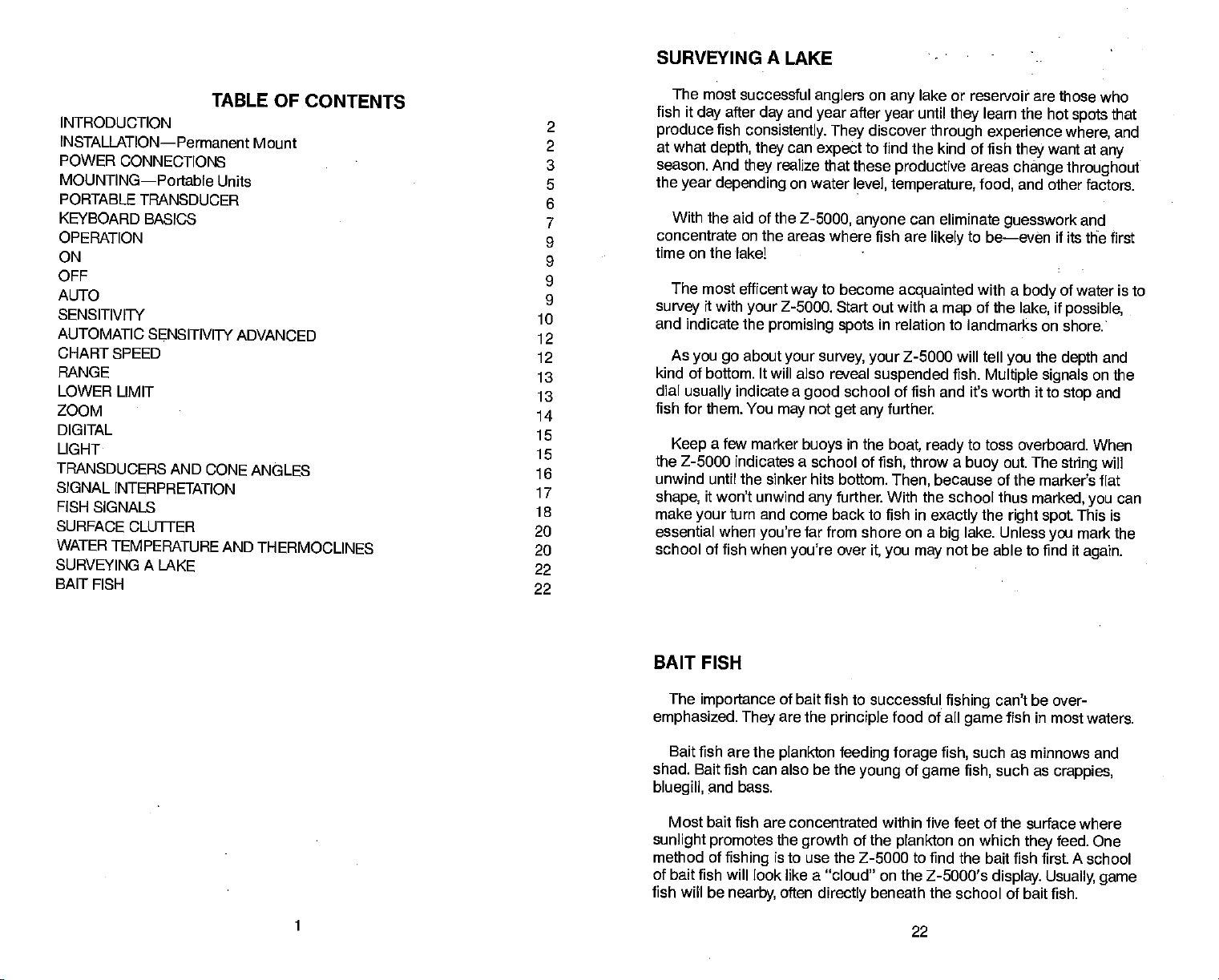
The Z-5000 can detect this invisible
sensitivity
will
probably
have to be turned
011
LL
E:::
AUTO.
an...
Hi
Sn
layer
up
HE::::::
IEEE
in the
water,
to see it.
V
but the
THERMOCLINE
Figure
17
INSTALLATION
Mounting
The Z-5000 can
clearance when tilted
base allow wood
attached to aluminum
suggest placing
to secure the
behind the unit to
A 11/a" hole in the base
transducer cables to be routed
surface. The smallest hole
through
passed up
wire can be
cables have been
adhesive
—Permanent
be installed in
for the best
screw or
a
piece
mounting
through
with sheet metal screws.
panels
of
plywood
hardware.
attach the
of the
that will
This will allow the transducer connector and cable to be
is ¾".
through
pushed
(RT,
the hole
DOWN
routed,
the bracket can be offset so that the
or
and
through
the
hole is covered.
convenient
any
viewing angle.
bolt
mounting.
on the back of thin
Make certain there is
and transducer cables.
power
gimbal
straight
hole
bracket allows the
down
the transducer connector
pass
gimbal
bracket,
the bracket and dash. After the
be filled with silicone rubber
may
location,
provided
Holes in the bracket
The bracket can be
However,
fiberglass panels
enough
power
through
the
then the
majoritypf
mounting
power
there is
we
room
and
cable
the
PDF compression, OCR, web-optimization with CVISION's PdfCompressor
21
2
Page 4
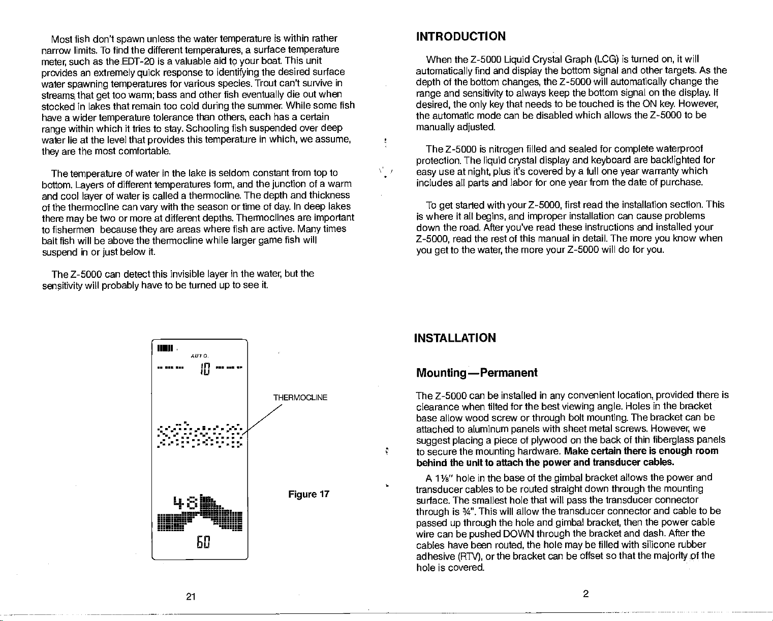
Power
Connections
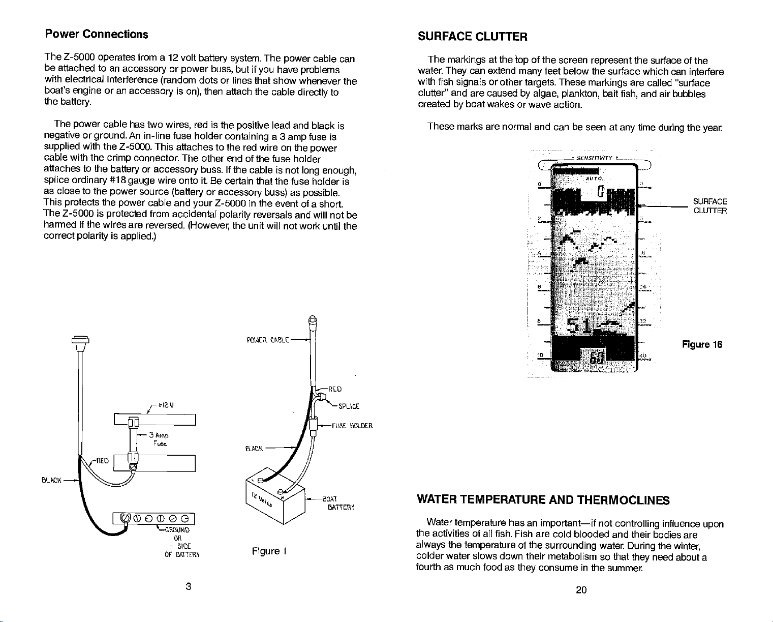
SURFACE CLUTTER
The Z-5000
be attached to an
with electrical
boat's
the
battery.
The
negative
supplied
cable with the
attaches to the
splice
as close to the
This
protects
The Z-5000 is
harmed if the wires are
correct
operates
engine
power
or
ground.
with the
ordinary
the
polarity
accessory
interference
or an
accessory
cable
has two
An
Z-5000. This attaches to the red wire
connector. The other end of the fuse
crimp
battery
#18
gauge
power
power
protected
is
applied.)
from a 12 volt
(random
wires,
in-line fuse holder
or
accessory
battery system.
or
power
buss,
dots or lines that show
is
then attach
on),
red is the
containing
buss. If the cable
but if
positive
wire onto it. Be certain that the
source
cable and
from
reversed.
(battery
accidental
or
accessory buss)
Z-5000 in the event
your
polarity
(However,
the unit will not
VOWER tPLE
The
have
you
the cable
lead
a 3
on the
is not
cable can
power
problems
whenever the
directly
and black is
fuse is
amp
power
holder
long
fuse holder is
as
possible.
of a short.
reversals and will
work until the
to
enough,
not be
The
markings
water
They
with
fish
clutter"
created
signals
and are caused
by
These marks
at the
can extend
or other
of the screen
top
feet below the
many
targets.
These
by algae, plankton,
boat wakes or wave action.
are normal and can be seen at
_________ SENS!TtI/!TY -
1-
:
4%;
represent
markings
bait
4&?O
the surface of the
surface which can interfere
are called "surface
fish,
any
and air
time
bubbles
during
—
/
S.,
the
year
SURFACE
CLUTTER
Figure
16
J
-RED
¶\DLDER
-SIDE .
OF sgTER'l Figure
3
-8CM
3PCVTER
1
WATER TEMPERATURE AND
Water
the activities of
always
colder water
fourth as much food
temperature
the
temperature
slows down their metabolism so that
has an
all fish. Fish are cold blooded and their
as
important—if
of the
surrounding
consume in the
they
THERMOCLINES
20
not
controlling
water.
summer.
During
bodies are
the
need about a
they
influence
upon
winter,
PDF compression, OCR, web-optimization with CVISION's PdfCompressor
Page 5

Remember,
to
fish
with the
The
due to the
shallow
fish in
due to
all,
display.
this
depth.
Compared
because the
graph's
as a
graph,
the screen than
Very
show a
fish will
Large
water to see
surface
turned
One of the best
segment
the better the screen resolution
as
high
medium to
there must be some movement
main
the arch.
engine
in
gear
Usually
of the water will affect
cone
water,
the narrow cone diameter
the 20
Even
to a
pixels (dots
markings.
and
arch,
partial
arch,
diameter. For
angle
the
signal displayed
degree
paper graph,
on the
Therefore,
it
requires
a
paper graph.
probably
or a
shape
the
but
transducer has
a bit more work
will not arch at
sensitivity
develop
depth
small fish
the arch. Because of water
clutter, thermoclines,
high enough
of the
possible
deep
ways
water,
without
water,
U
______
to
fish arches.
get
to
get
for
example
getting
this method
at
the Z-5000 cannot show
etc.,
between the boat and
means
this
trolling
a minimum throttle
the size and
example,
on the Z-5000
at
setting.
shape
the cone
if
very
of the fish arch
passes
may
and the resolution limitations of the
a 3 foot diameter at
only
an Z-5000 cannot
screen)
similar to an arch if
fish arches is to
are much
needs to be
conditions,
the
sensitivity
all,
show as fine of detail
than a
larger
fish arches as well
to read and
initially
while medium
they're
turned
such
sometimes
expand
or "zoom"
up
as
30 to 60 feet The smaller
will be.
Then,
turn
up
the
sensitivity
too much noise on the screen.
should work to
display
In
[LI
a
the
slow
speeds
over
not arch at
paper
interpret
sized fish will
in
cannot be
deep
in
deeper
heavy
the
segment,
water
a
as
In
fish arches.
TRANSDUCER
Installation instructions
supplied
instructions
a
with the transducer
carefully
for the
before
permanent
in a
separate package.
start
you
mount transducer
installing
the transducer.
Please
are
read the
NOISE
Electrical
routing
of the
from the
wire for
best results,
wiring. Also, bilge pump wiring
keep
VHF
than even the
Z-5000's
VHF
•
•
If there
still
boat
cause
rather
noise
The faster a boat
noise
owner's
noise
away
noise
engine
keep
picked up by
from other
generators
to the instrument
the
power
it
largest
the tachometer which
the Z-5000's cables
radio antenna cables
engine's
and transducer
power
radio antenna cable.
is no noise—interference—on
with the
speeds, worsening
engine running
is acoustic
mechanically
is created
on the
manual for
noise,
by
travels,
display.
induced
air bubbles
To eliminate
proper
the
possible
is the
radiates RF
and
can
from
away
radiate RF
harness.
wiring
as the
cables as far
in
neutral,
boat
or cavitation.
noise from the transducer.
passing
the more
mounting techniques.
cable can be minimized
power
sources of electrical interference.
engine's wiring
This harness
panel.
transducer cables
sometimes radiate noise so
(radio frequency) energy.
those wires.
energy
It is
very important
harness
usually
away
at
higher power
as
away
that runs
contains a
from the
to
keep
possible
try
from
the unit when the boat is
but interference
increases,
speed
This noise is not
over the face of the transducer.
begins
then a
air bubbles increase and
this
problem,
read the transducer
at slow
probable
electrical,
Usually,
generate
by
One
For
engine
to
levels
the
a
sifting
but
acoustic
I.'
Figure
15
I
Ilk'
-
_rJ
PDF compression, OCR, web-optimization with CVISION's PdfCompressor
19
4
Page 6

lVlounting—Portable
Units
Only
FISH SIGNALS
Installing
The Z-5000
them,
the
front of the
case with the
battery
batteries.)
contact with the
compartment
of
the sonar unit and turn it on.
isn't
received about
batteries have
stock.
as dead ones
the Batteries
turn the
board
The
check
the batteries for
Always
portable requires
battery
spring
may
lid
box
compartment. Open
terminals
need to be
battery
board is
terminals,
and latch the case.
portable
units result from
a limited shelf life. Be sure
remove
can leak and corrode the
them from the
two
six-volt lantern
upside
down and release the
it
and slide the two
against
placed
specially
regardless
the
in
of
Plug
The Z-5000 should
proper voltage.
compartment
batteries. To install
battery
its slot before
designed
their
the
using
the batteries
plating
board.
to assure
position.
cable
power
Most of the
begin working.
stale batteries. All
before
on the
two latches on
batteries into the
the
(Note:
installing
Close the
complaints
you buy
battery
the
proper
into the back
If
it
carbon
are fresh
storing
the
board.
Figure
2
unit
The
signals displayed
various
marks created
bottom.
that
this is shown below. The distance to a fish
sonar's cone of sound
moved into the center of the
and as it
shown
up,
pointed
adjust
and error until
shaped markings
Individual fish
separates
If a
partial
but not
it until
them from their
moves out of the
in "C".
arch
back
straight
the fish show the distinctive arch. This
the correct
by
can,
down,
down. If
on the
in
or the
noise,
at
times,
is shown as "A"
Z-5000
certain
solid,
be
stationary
cone,
cone,
by
patterns,
continuous
distinguished
surroundings.
Figure
the distance to it will be
the distance will increase
occurs most of the time on
or
vice-versa)
it could be the
the transducer is mounted on
mounting
is achieved.
fish can be identified
as
opposed
markings
by
to random
made
a
characteristic arch
The reason for
when it moves into the
14. When the
unit
your
transducer is not
may
fish has
shorter, "B",
again
mark curves
(the
the
transom,
take some trial
'IIIIIHI
by
by
U
the
as
ri
B
At
Figure
5
PDF compression, OCR, web-optimization with CVISION's PdfCompressor
14
18
Page 7

The 20
water,
deep
narrow cone
deeper depths
Both
readings,
model because
shallow
signal
Transducers on salt water boats need to be
anti-foulant
barnacles
transducer's
will decrease
paints
most marine
degree
while the 8
water
8
degree
even
edge
tells
specifically designed
transducer is almost
degree
environment,
angle
since the sound
and 20
though
you
of the
whether
you
to
paint
and other marine
sensitivity.
transducer is used
(300
is more desireable because it can
degree
the bottom
are
seeing
shows
signal
you
prevent organisms
Do not use a metal based anti-foulant
the transducer's
dealers.
always
feet—fresh
energy
more of the bottom.
are over
growth
senstivity.
is concentrated in a smallerarea.
transducers
signal
the true
you
rocks, mud,
from
will cause a decrease in the
for transducers.
the best to use
in salt water. In a
mostly
100 feet—salt
water,
penetrate
accurate bottom
give
is much wider on
Remember,
The rest of the
depth.
etc.
painted
growing.
There are
They're readily
with a
If
unchecked,
special
in fresh
water)
to much
the 20
degree
the
thin
coat
as it
paint
anti-foulant
available
the
of
at
Portable Transducer
The
portable
means of a suction
transducer is attached to the transom of the boat
The transducer should be mounted on an area
cup.
of the transom that is free from bubbles while the boat is
important
on the Z-5000 as random dots.
Assemble the transducer as shown in
end of the cord
end
should
Clean
Once the
attach
above the bottom
the water
because air bubbles cause cavitation noise which is
3. Make certain to tie one
Figure
to the transducer bracket This will
provided
with the transducer to the boat and the other
prevent
the loss of the transducer
it come off.
the chosen area of the transom before
position
it
as
firmly
has been
as
possible.
of the
edge
determined,
The suction
hull,
moisten the suction
which allows the transducer to be in
at all times.
setting
should be mounted
cup
the suction
running.
displayed
cup
by
This is
cup.
and
just
SIGNAL
Because
give you
is
passing.
fairly
narrows
because mud absorbs the sound wave and returns
the
up
sensitivity
automatically
The
hard. If it increases while in the same
moved over a soft bottom. If it
course,
also
Big
bottom level
height.
clearly
Brush
the bottom
signal
PDF compression, OCR, web-optimization with CVISION's PdfCompressor
INTERPRETATION
Z-5000 is both
your
an accurate
picture
A bottom of firm
wide
down,
sensitivity.
If the automatic
signal.
then it means that
If
you
bar As the boat
increase the
sensitivity
change.
rocks or
visible as a short line
is not as
bar will
as the water
stumps
signal.
If
watch as
you
usually
lies on the bottom and shows
signal.
strong
depth
The
Brush
extremely
sensitive and
of the kind of bottom over which
sand, gravel, shell,
sensitivity
have moved over
you
have the automatic
passes
help you
on a smooth
height
you approach a post
signals
over the mud
sensitivity
increases or
extending
to maintain a
in
determining
decreases,
bottom send back
of the
signal depends
look similar to
depth
above the bottom
as rock.
17
or hard
turned
is
senstivity
if the bottom
of
water,
then it is over a
decreases,
or a tree
up
large
powerful,
clay
and the
off,
a mud bottom
a weak
turned
bottom,
the Z-5000 will
bottom
good
then the boat has
hard bottom. Of
the
sensitivity
signals
on the
stump,
signal.
as
clumps rising
rocks,
it can
boat
your
returns a
signal
Turn
signal.
on,
is
soft
above the
target's
watch
signal.
or
will
the
it will be
above
however their
p
3
Figure
6
Page 8

KEYBOARD
CHART The
control red
of
keys.
chart
slow to FAST.
FAST
speed.
The chart
slopped
pressing
same Uma
chart
the CHART
by
The
Z-5000 has 32
speeds,
ranging
Pressing
key speeds
The slow
display
and started
both arrow
up
key
can
BASICS
is
speed
group
from
very
the
the
chart
reduces it
be
again by
at
the
keys
SENSITIVITY
LIGHT
TRANSDUCERS AND CONE ANGLES
The sound waves from
cone
shaped beam,
between the outside
offers a choice of
Eagle
cone
In other
transducer of the same
the use of
of
performance.
Generally,
for
operating
angle
the 20
transducer covers
angle
words,
any
allows
degree
that will
any Eagle
other manufacturers'
wide cone
in shallow to medium water
to see more of the underwater
you
cone covers an area about six feet
the transducer
spread
much like the beam from a
of the cone is called the cone
edges
transducers with either an 8 or 20
interchange
with
of the 192 kHz sonar
any
sonar instrument can be used with
with
frequency
no loss of
transducer will result in a loss
transducers
angle
(20
depths.
about a two foot circle.
only
degrees)
out into the water in a
flashlight.
performance.
The 20
world.
across. The 8
The
angle
angle.
degree
products.
any Eagle
However,
are
degree
In
15 feet of water
ideally
cone
suited
degree
ZOOM The
expanded
display by using
ON
OFF
the Z-5000 on and off. To turn it
on,
simply press
turn it
off,
press
can be
range
or
zoomed" on the
this
key.
Thesekeysturn
the ON
the OFF
key.
key.
To
Figure
cone
Depth
50
1100
lisa
1200 28 71
Angle
Diameter
-
7ff. 188.
14 35•
21 53•
50'
100'
Figure
4
13
150'
200'
80at3db
7
16
PDF compression, OCR, web-optimization with CVISION's PdfCompressor
Page 9

DIGITAL
A
complete digital
discriminates
thermoclines,
fish,
bottom
"locked on" to the bottom
depth.
When the Z-5000 is first turned
it will
display
the
sonar is built inside the Z-5000. It
between the valid bottom echoes and false echoes from
or other
depth
signals.
signal.
in the lower left of the
2
-4
4
A
4
I?'
6
L.
Although
performance
arrow
into a
One reason to use the
travel at
to know the bottom
The
automatic mode.
LIGHT
A
light
first turned
used to turn the
the left and
To turn the
lights
it is not
in the chart section of the
keys
digital
high speed
digitalis
is
provided
on,
right
lights
will also
necessary
out of
your digital
sonar
turned off whenever the Z-5000 is taken out
the
lights
go
and allows it to better track the bottom
only
digital
from one
depth.
for
operation
will flash for 6 seconds. The
lights
off and on. To turn the
arrow
keys
off,
press
out when the Z-5000 is turned off.
both arrow
The
digital display
on,
Once it has
-
SEWSWVIIV
AUTO
the
will flash "0" until it has
digital
acquired
display.
t
/'
t1"..tfls
"Jill-'-—-
in normal
sonar,
in this manner would be if
of a lake to another and
part
of the Z-5000 at
at the same time and the
—
to
use,
the chart
stop
keyboard.
lights
at the same time
keys
get
This turns the Z-5000
night.
on,
automatically
will show
the bottom
Figure
the maximum
by pressing
signal.
are
you
you just
of the
When the unit
sensitivity keys
simply press
will
lights
stay
again.
only
depth,
both
going
want
both
on.
The
the
12
to
are
0
SENSITIVITY
LIGHT
____
tn
SENSITIVITY These
the
control
(rhe digital's sensitivity
automatically adjusted4lhe
receiver
speeds
adiustment
conditions. The left arrow
decreases
right
graph's sensitivity.
sensitivity
whiph
over a wide
the
arrow
key
keys
is
has 32
allows
sensitivity,
increases it,
range
key
the
of
k=ks
-fl
+
rzooM
+
The
AANGE
to' setect different
yob
ranges by pressing
down
ranges.are:
200,
range keys
arrow. The available
10,20,40,60, 100,
and 400.
the
depth
up
allow
or
]EL
AUTO TheAUTO
switches the Z-5000 in cr out of
the automatic mode, When the
t_OFFJrON_I
L
is
Figure
5
Z5000 is first turned on, it
automatically adjusts
sensitivity
thid the word "AUTO" will be
displayed
screen.
By pressing
can take control of the
key, you
Z-5000, making
adjustments
the Z-5000 is in the automatic
the word "AUTO" will be
mode,
displayed
display,
key
and
near the
near the
the
range selection,
of the
top
the AUTO
manual
as desired, When
of the
top
PDF compression, OCR, web-optimization with CVISION's PdfCompressor
15
8
Page 10

nnrn ATIflkI
I— flflI
When the Z-5000
the bottom
Z-5000
can
I'.tI1
depth,
left
be
sets
in this automatic mode and used for
the water and bottom
function of the Z-5000
the unit to the
surrounding
ON
The ON
placed
in
turn the
then
stop
display
depth display.
displayed.
and the
is located in the lower
key
this location so that it can be
Z-5000
on, press
after six
seconds. The chart will
number "0" will flash. This
After
the unit has found the
is first turned
the
sensitivity
conditions
can be
conditions can be made.
on,
level,
they prefer.
manually
[ON
right
the ON
key.
it
automatically
and much more. If
However,
adjusted
easily
The chart
bottom,
so that "fine
corner of the
found—even at
lights
begin
scrolling
number is the
the
finds and
finding
virtually every
displays
desired,
fish and
tuning"
keyboard.
night
will
begin flashing,
across the
bottom
digital
will be
depth
It
is
To
the
of
For
example,
until the
key
maximum
that
the Z-5000 can reach is
the
plus
quality
The lower limit
However,
is less than the
mode. For
100
feet,
the Z-5000 will
feet
to
lower limit on the
lower limit the Z-5000 can
of the transducer installation.
can be
the Z-5000
depth
example,
with a bottom
GSENS)TV!TY
U!]
set the
won't
from 0 to 60
range
display
dependent
changed
accept
feet, press
reads 60. NOTE:
display
even if the Automatic function
an
is 400
on water and bottom
if a lower limit is selected that
entry
feet
of the bottom while the Z-5000 is in the
if
the Z-5000 is in
at
signal
leave the lower limit at 100 feet
80
feet
Automatic,
and
and the
select a lower limit
you
Efl
the down
although
the actual
conditions,
Automatic
range
A
arrow
the
depth
is on.
is 0 to
of 60
V
SCALE
OFF
To turn the Z-5000
erased.
off,
AUTO
When the Z-5000 is
switch it into the
above the ON
erased,
digital display
control of the Z-5000. The Z-5000 can be
mode at
key.
auto
sensitivity
will be turned off and
time
any
first turned
manual
The word
by simply pressing
LOFF J
and HOLD the OFF
press
rAuTO I
_______
mode, press
AUTO at the
and auto
ranging
the automatic mode is on. To
on,
the AUTO
will have
you
the AUTO
9
until the
key
which is located
key
of the
top
will both be
returned to the automatic
display
cancelled,
complete
key again.
display
will be
plus
manual
the
is
Figure
10
ZOOM
Often it's desirable to
show more detail.
of the
targets
shown on the
the manual mode and the
new
the
upper
seconds,
segment
seconds it will
will be 30 to 60
range
limit and lower limit will be
then
disappear.
size is
displayed
disappear.
expand
Pressing
MARKERS
ZOOM
t______
or "ZOOM" a section of the
the ZOOM
lower half of the
is 0-60
range
feet The
In this
example,
in the
upper
aliows
key
feet,
segment
displayed
the
middle of the
14
10
you
display.
the ZOOM
press
size or distance between
nil
'
aM
Figure
display
to double the
For
example,
key.
11
to
if it's in
The
on the screen for six
segment
size is 30 feet The
display.
After 6
size
PDF compression, OCR, web-optimization with CVISION's PdfCompressor
Page 11

automatic mode is
If the
reached.
speed
and
Turning
to be attained. There
31
steps
the automatic
in automatic.
At times it is desirable to
echo before it scrolls
arrow
display.
on and off to
arrow
setting.
on the screen. The
mode.
the chart section at the same time once
in
keys
While the
signify
keys again
If the
digital
display
that the unit is in the freeze mode.
will start
sonar is
digital
maximum chart
the
on,
mode off will allow the maximum
are 32
steps
or "freeze" the
stop
off the screen.
is
stopped,
the
display moving
the bottom will continue
on,
does not
I
of chart
Pressing
the
top
when
stop
cannot be
speed
speed
display
both the
in manual mode
to examine an
right
chart
and left
will freeze the
to be
will flash
both
speed
displayed
line on the
display
Pressing
at the last chart
the chart is in the "freeze"
SENSITIVITY
When first turned on,
the
means
computer
the automatic
The
display.
sensitivity
correspondingly.
extend across
sensitivity
to find
mode or it can be
sensitivity
When
is
increased,
the
the
and lock onto the
level is
sensitivity
When the
top
SENSITIVITY
____
the Z-5000 is in the
and
range
displayed by
is at
the bar will travel to the
sensitivity
of the
display.
LIGHT
are
automatically adjusted by
bottom. The
manually adjusted
a horizontal
minimum,
is set
AUTO SEARCH mode.
the micro-
sensitivity
can be
to suit conditions.
bar at the
the bar is
right increasing
to
maximum,
short.
very
the bar will
top
This
left in
of the
As
in
length
RANGE I__+
the Z-5000 is in the
When
matically change
depth changes.
or zoom in on a
range
limit
setting by using
The
depth range
display.
determine
indicates
feet,
feet
The scales marked on
etc.
For
At
the
depth
one
foot,
The scale markers can
example,
to
keep
times,
the "ZOOM"
is
always
of a
while on the 0-20
if the
automatic
the bottom
however,
The
target
displayed
target.
range
the sides of the
On the 0-10 foot
is
+
the
mode,
on the
signal
it
be desirable to
may
limit can be set
upper
described later in this
key
at the
top
display
foot scale each mark
also be used on
0-100
each mark is
feet,
ranges
display
expand
to half the lower
bottom of the
and
will
each mark
range,
ranges
deeper
will auto-
as the bottom
the
section.
help you
indicates two
than 60
to 10 feet.
equal
SENSITIVITY
BAR
o
— I—
srJsIrl'!TY
AUTO.
•rnr.rr
fr
—S
I.
Figure
6
LOWER LIMIT
To
change
displayed
off.
automatic
the down arrow
down arrow is
scale.
shallower scale.
and. 400feet.
range
(Note:
Pressing
and
This also
the
at the
top
mode is
key
pressed,
the
The available
The
display
lower
of the
disables the automatic
on,
in the RANGE section
up
display
the new lower, limit
PDF compression, OCR, web-optimization with CVISION's PdfCompressor
first make certain the word
limit,
screen,
press
signifying
the AUTO
that the automatic mode is
sensitivity function.)
once
key
of the
the lower limit will switch
arrow
will
will
key
immediately
depth
change
ranges
are
change
at the bottom
13
the lower limit to the next
"AUTO" is not
to disable it.
keyboard.
to the next
40, 60, 100, 200,
10, 20,
to the new
of the screen.
If the
Next,
Each time the
press
deeper
depth
.
To
manually adjust
sensitivity
disappear,
the
the desired
manner. Notice how the
When
an
left, indicating
the
will be turned off. The word AUTO at
signifying
sensitivity, press
indrease in
change
level. The left arrow dec.reases
you press
on the
the
sensitivity, press
that the Z-5000 is
and hold the
sensitivity
the
right
sensitivity.
the
sensitivity
display.
right
bar
arrow
key,
Pressing
has decreased
the AUTO
in the manual mode. To increase
arrow
sensitivity
moves as
the bar
the
10
moves to the
left arrow
accordingly.
key
the
key
of the
top
until the
in
you change settings.
moves the bar to the
key
and auto
once,
display
sensitivity
same
the
is at
right indicating
You'll also see
will
Page 12

7 demonstrates a
Figure
the
right,
clutter is more
sensitivity
TOO
SENSITM1Y
is
adjusted
pronounced,
LITTLE
with too little
graph
properly;
and the bottom
sensitivity,
a fish is now
has
signal
_________ SEWS)?! WIlY
2
1
while
visible,
the surface
widened.
SENSITMTY
ADJUSTED
PROPERLY
on the
to
AUTO
receiver will be
up
automatic mode. This
by
too
SENSITIVITY ADVANCED
When the Z-5000 is in
the bottom
The
sensitivity
adjusted
signal. (There
level can
the Z-5000 is not
for water conditions.
high
the automatic
to ten
be
may
enough
be desirable if
the Z-5000 will increase the
then add in the level
signal,
sensitivity up
to the maximum
OPERATION
steps
are 32
changed
mode, the
above the minimum
of
steps
while the Z-5000 is in the
the level of
sensitivity
sensitivity available.)
to show fish or other small
Once the
sensitivity
you programmed.
may
sensitivity
enough
be added.
has been
to
pick up
If
desired,
of the
required
sensitivity
detail,
changed,
the bottom
amount of
any
to
chosen
or if it
pick
i
Figure
When the horizontal bar reaches the far
the
sensitivity
second bottom echo
returning signal reflecting
to
the bottom and back
trip
7
level is at maximum, If
may appear.
off the
This is
surface of the
This is
again.
—I
4
IT
hand side of the
right
high
sensitivity settings
normal and is caused
water,
caVed "second echo".
*
Figure
are
making
<
8
screen,
used,
the
by
a second
To
lo
simply press
left
arrow
adjust
key
the
sensitivity
either the
<
to decrease it
while the Z-5000 is in
right
arrow
key>
to
the automatic
increase the
mode,
sensitivity
or the
taw
k=Jfc4i
CHART SPEED
the Z-5000
When
at a
pre-detem,ined
the
the desired
key.
top
appear
chart
bar will
a
increasing. By holding
be
right
arrow>
right
Whenever either of these
of
speeded up
speed.
the
display
in a window near the
start
If
moving
speed.
side of the
is turned on for the first
If
speed.
in the CHART
key
To slow
will
change
you press
to the
or
slowed down. When
screen,
a
the
keys
to a dashed line and the
top
and hold the
right, signifying
either the
the chart
higher speed
section of the
display,
are
of
the
right
press
pressed,
display.
right
that the chart
or left
the horizontal bar
is at
speed
time, the chart
is
desired,
and hold
the
This bar
arrow
arrow
its maximum value.
press
keyboard
the left arrow
sensitivity
letters "CHT' will
represents
>
for
key
example,
speed
the
keys,
reaches the far
scrolls
speed
and hold
until it runs at
c
bar at the
the
the
is
display
can
To
turn Auto
automatic
and on at
Sensitivity
sensitivity
time
any
be turned off or on
back
on,
control and auto
by pressing
separately by pressing
the AUTO
press
11
the
ranging
AUTO
key. Remember,
functions are turned off
The two controls cannot
key.
the
AUTO
key.
both
111 111111
NUN It
12
Figure
9
PDF compression, OCR, web-optimization with CVISION's PdfCompressor
 Loading...