

Page 1

D4800 Sentient
Technical Manual
Version 0209-01
Dycon Ltd
Tel: +44 (0)1443 471 060
Fax: +44 (0)1443 479 374
Cwm Cynon Business Park, Moutain Ash, CF45 4ER – UK
www.dyconsecurity.com
info@dyconsecurity.com
Page 2

TABLE OF CONTENTS
1. Introduction 4
1.1 Description 4
2 User operation – controlling Dycon Sentient D4800
using the key switch
2.1 User operation – controlling Dycon Sentient D4800
using the key switch
2.2 Disarming the system 5
2.3 Operation “An Alarm” 6
3 User operation – control using the hand-held
controller
3.1 Arming Dycon Sentient D4800 system 6
3.2 Disarming Dycon Sentient D4800 system 6
4 User operation zone omit 7
5 Engineering functions 8
6 Preparing a Dycon Sentient D4800 system for use 9
Parts required 9
Sealed lead acid batteries, 7AHR 12V as required 9
6.1 Dycon Sentient D4800 set-up (overview) 9
6.2 Dycon Sentient D4800 internal PIR set-up 10
6.3 Dycon Sentient D4800 external power and GSM aerial 11
6.4 NVM fitting 11
6.5 SIM card selection 11
6.6 Fitting the SIM card 12
6.7 Learning detectors into the Dycon Sentient D4800 system 12
6.8 Removing detectors from zones 12
6.9 Detector types / zone number 13
6.10 Learn pins 13
7 Installing a Dycon Sentient D4800 system 14
7.1 Main controller siting 14
7.2 Site survey GSM 14
7.3 External aerial 15
7.4 Radio background noise test 15
7.5 Installation of detectors 15
7.6 Radio siren unit siting 16
7.6.1 Siren tamper inputs 16
7.7 PIR detectors 17
7.7.1 Preparing a Dycon Sentient D4800 PIR movement
detector for use
7.7.2 Dycon Sentient D4800 PIR link setting 17
7.8 Universal transmitter 18
7.9 Smoke detector siting 19
7.10 Other detectors 19
8 Functional testing of a Dycon Sentient D4800 system 19
8.1 Basic test set-up / GSM communication tests 19
8.2 Functional testing 19
8.3 Peripheral detector signals 20
8.4 Alarm test calls 21
8.5 Siren test 21
8.6 Mains supply 21
5
5
6
17
D4800 Sentient Technical Manual – D4800TM/09G/v1 2
Page 3

TABLE OF CONTENTS (continued)
A
9 Operation zone supervision 21
10 Radio signals 21
10.1 Jamming 22
11 SMS – the GSM SMS (Short Message Service) 22
11.1 SMS alarm reporting 22
12 SMS remote control 22
12.1 Remote control GMS / SMS 23
12.2 Remote state query 24
13 GSM and battery strength indications 24
14 Battery fitting 25
14.1 Deep discharge damage 25
14.2 Dycon Sentient D4800 battery cut-off module 25
14.3 Battery recharging 26
14.4 Low battery reporting 26
15 Remote programming of the Dycon Sentient D4800 26
16 Dycon Sentient D4800 product changes 26
16.1 Dycon Sentient D4800 software version 26
17 Troubleshooting 27
18 Appendix 1 29
19
20 Appendix 3 31
ppendix 2 30
D4800 Sentient Technical Manual – D4800TM/09G/v1 3
Page 4
Sentient D4800
Technical Manual
1. INTRODUCTION
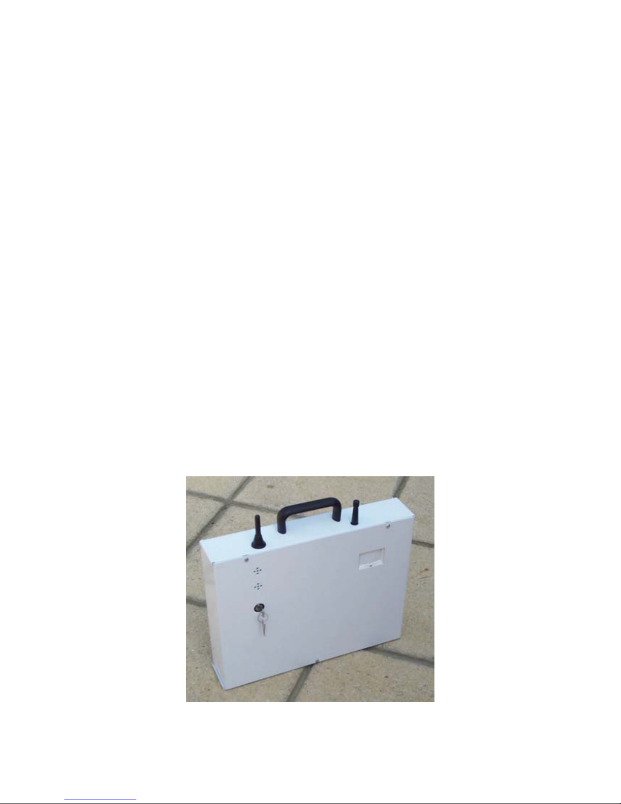
1.1 Description
The Dycon Sentient D4800 is an advanced portable auto-reporting intrusion alarm system
featuring simple key-switch control, using radio detectors and the GSM network, therefore
eliminating the need for any wires.
The Dycon Sentient D4800 can transmit alarm signals to an Alarm Receiving Centre (ARC)
using the GSM (Global System for Mobile Communications) data network.
The Dycon Sentient D4800 can also be programmed to send SMS text messages (Short
Message Service) to GSM portable phones and pagers.
Several types of radio alarm detectors can report into the control unit.
Arming and disarming of the alarm is possible using a key on the unit or by a radio hand-
held controller, or by SMS from any GSM portable phone or from a PC and modem using the
programming and downloading software.
The Dycon Sentient D4800 control and optional radio siren units use SLA batteries (Sealed
Lead Acid) batteries for mains-free operation for up to 100 days (depending upon batteries
fitted). An optional power supply is available so that a mains supply can be used to power
the units, or recharge the unit’s batteries.
The Dycon Sentient D4800 is housed in a steel case. It can take up to 4 x 7Ahr batteries.
D4800 Sentient Technical Manual – D4800TM/09G/v1 4
Fig. No 1
Page 5

2. User Operation - Controlling the Dycon Sentient D4800 using the key switch
User control is achieved by a two-position key or a hand-held remote control unit. Control
using SMS commands is also possible (see section 12). The unit only has two operating
modes “Armed” and “Standby”
NOTE: If the key is trapped in the lock (horizontal) then the system is in “Standby” mode
(off). If the key can be taken out of the lock (vertical) then the system is active (on).
2.1 Arming the System
1 With the key, move the key switch to the “Armed” position and remove key.
2 The “Exit Time” will now start. This period is pre programmed in the NVM.
3 The internal PIZO sounder will come on (Exit Tone).
4 A continuous sound indicates that the system is clear - a pulsing sound indicates that
there is a fault present.
NOTE: ANY detector that is triggered during the exit period will make the sounder
pulse.
5 The exit tone will be a continuous tone that will pulse on and off at a fast rate when
there is less than 10 seconds of the exit time remaining.
6 During the “Exit Time”, leave via the “Exit Route” and the “Exit Door” and secure the
protected premises.
7 When the “Exit Sounder” becomes silent, the system has armed. An `Armed' signal
will be sent to the ARC and SMS message.
8 If a fault is still present at the end of the exit period, the alarm siren (internal and
external if fitted) will come on for approximately 10 seconds to indicate a BAD Arm.
The Dycon Sentient D4800 system will still continue to attempt to arm if the fault then
clears. “Full” arming will then take place. If the fault remains then the Dycon Sentient
D4800 will never fully arm.
NOTE: The “Bad Arm” signal will only be generated once.
9 When the system is armed, any intruder that is detected will cause an alarm to be
generated.
2.2 Disarming the System
1 Enter the protected premises via the “Entry Door”. The “Entry Time” will start
indicated by the “Entry Sounder”. The sound will be a continuous tone that pulses on
and off when there is less than 10 seconds of the entry time remaining.
2 Go to the control unit via the “Entry Route”.
3 Insert key the key turn move the key to the “Standby” position.
4 The “Entry Sounder” will stop.
5 The system will now be in the “Standby” mode.
6 A ` standby' signal will be sent to the ARC and SMS message sent.
Notes:
1. If the “Entry Time” finishes before the control unit is disarmed a full alarm will be
generated.
2. The “Entry Sounder” may be silent (dependent upon programming).
3. During the “Entry Time” all detectors programmed as “Entry” or “Entry Route” will be
ignored, all other detectors can still generate an instant alarm if they are triggered.
D4800 Sentient Technical Manual – D4800TM/09G/v1 5
Page 6

4. When the system is in standby mode, only “Tamper” alarms can be generated and
y
A
)
signalled. “Alarm” inputs will be ignored.
2.3 Operation “An Alarm”
1 With the system armed, and when an intrusion is detected, the system will go into
the “Alarm” mode. An alarm signal will then be transmitted to the ARC and SMS
messages sent.
2 The “Siren Unit” may remain silent for a preset delay period (if programmed).
After this time the siren will sound for the preset “Siren Period”.
3 If the unit is not returned to Standby mode, then the system will automatically re-
arm awaiting another alarm detection input.
4 The user may insert the key and turn to “Standby” mode or use the remote control
at any time.
NOTE:
- Activation of any “Final Exit” mode detector will only start the entry timer and will not
cause an instant alarm.
- Detectors working as “Entry Route” mode will be ignored if the entry timer is running,
otherwise they will cause an instant alarm.
3. USER Operation - Control using the hand-held Controller
LED indicates Radio Transmission
RMED Button
Zone Omit Button (See Section 4
STANDBY Button
Operate these two keys together to
generate a PA (Panic) alarm (+
Learn mode).
Fig. 11
3.1 Arming the system
1 Ensure that the protected premises are vacated and secured.
2 Ensure that
ou are within 50 metres of the control unit.
3 Press the “Armed” button.
4 The system will immediately change to the `armed' state. An `Armed' signal will be
sent to the ARC and SMS message sent.
3.2 Disarming the system
1 Ensure that you are within 50 metres of the control unit.
2 Press the “Standby” button.
3 The system will immediately change to the `Standby' state. A `Standby' signal will
be sent to the ARC and SMS message sent.
D4800 Sentient Technical Manual – D4800TM/09G/v1 6
Page 7

4. User Operation Zone Omit
The Dycon Sentient D4800 alarm system has a zone omit feature (if programmed).
Depending upon programming, a zone(s) may be omitted for a pre-set time (between 1 and
98 minutes) or may be omitted for an unlimited time.
If the “Zone Omit” feature is programmed, then its operation is as below:
1. With the Dycon Sentient D4800 armed, enter into an active zone. The external siren
will come on for 4 seconds (it will give audible warning of zone detection over the
whole installation).
2. You now have the normal “Entry Time” to press the 3rd (middle) button on the handheld controller.
a. If this button is pressed the zone entered will be omitted for the programmed time
or continually (depending upon the NVM programming).
b. If this button is NOT pressed within the “Entry Time” a “Full Alarm” condition will
be generated.
3. When a zone/s has been omitted, a “Common Omit timer “will be running. Thirty
seconds before the “Omit” time runs out (and zone/s becomes active again), the
external siren will come on and generate a reminder signal for 4 seconds (to give
audible warning of zone/s becoming active again). NOTE: If “Un-Timed Omit” is
programmed then a reminder signal will not be generated.
a. The user is to leave the omitted zone/s and they will become active again (see
paragraph 7 notes)
or
b. The user is to press the 3d controller button again which will restart the “Common
Omit” timer and leave all the omitted zone/s de-activated.
4. If a zone is already omitted and another zone is entered, then steps 1 and 2 will be
repeated. If action 2A is taken, this new zone will be omitted in addition to any
previously omitted zone/s. The “Omit” timer will be reset to the full time for ALL
zones.
5. The user may make ALL omitted zones instantly active by pressing the “Full Arm”
button on the controller (from outside the protected area/s). See paragraph 7 notes.
6. If the Dycon Sentient D4800 is turned from active to standby, then made active
again, ALL zones will become fully active i.e. the “normal” arming mode.
NOTES:
a. When the system tries to become fully active (time out or user pressing “Full Arm”
button) and if a fault is present, the Dycon Sentient D4800 system will go to step 2, if
the faulty zone/s are not omitted by the end of the entry time, then a full alarm will be
generated.
b. When zones are omitted a tamper condition on any omitted zone to be treated as a
full alarm.
c. Any number of zones may be omitted at the same time. If the system generates a full
alarm, but the siren has stopped and the panel has NOT been reset, when a user
enters a zone, that zone/ s may be omitted without any problems. However when the
system attempts to fully re-arm (from zone omit time out or user pressing the full set
button), it will operate as Note A above.
D4800 Sentient Technical Manual – D4800TM/09G/v1 7
Page 8
)
)
5. ENGINEERING FUNCTIONS
The “Engineering” functions include programming external detectors, testing, installation and
maintenance. Most engineering functions are controlled by using two pushbuttons, in
conjunction with a display and LEDs.
The functions of the LED’s are set out below:
GSM signal strength
Battery test mode
Zone Learning Mode
Dycon in Walk Test Mode
Dycon test call Mode
External 12 Volt supply
connected
(Indication only not a function)
Table 1
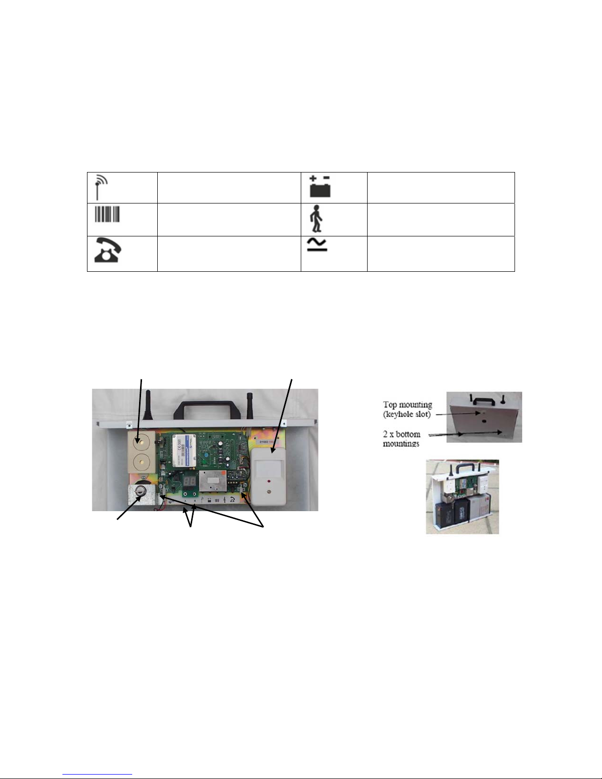
The main lid has to be removed (using a T20 TORX security driver*); this will then give
access to the battery compartment, NVM chip, SIM card and engineering controls.
NOTE*
On some units the lid is also retained by a security lock
Built-in Siren (if fitted
Built in PIR (if fitted) (see
section 6.2
Main Control
Key Switch
Fig. 2A Fig. 2B
Function Buttons
A and B
Battery
Connectors (only
fit one way)
Push button “A” is used to select the function required (as table 1 above)
Push button “B” is used to activate the function selected by button A
D4800 Sentient Technical Manual – D4800TM/09G/v1 8
Page 9
6. Preparing a Dycon Sentient D4800 System for Use
Parts required
• A suitable GSM SIM Card
• A programmed NVM Chip
• External detectors and siren as required
• Sealed Lead Acid batteries, 7Ahr 12V as required
Take care when handling and fitting batteries. They are heavy and an electrical short-circuit
at the battery terminals can be dangerous.
Take Care: the Dycon Sentient D4800 unit is heavy when fitted with batteries.
6.1 Dycon Sentient D4800 Set-up (Overview)
1 Open the control unit lid.
2 Remove the internal bag of keys and fittings.
3 Fit the NVM into the 8 pin IC socket inside the control unit. Note correct polarity. Pin
1 (notch or mark) towards bottom edge of PCB. (See section 6.4).
4 Fit the GSM SIM Card in the SIM socket inside the control unit. (See Section 6.6).
5 Connect the battery leads to the battery(s). Ensure correct polarity (see below) Do
not connect the battery leads to their sockets at this time.
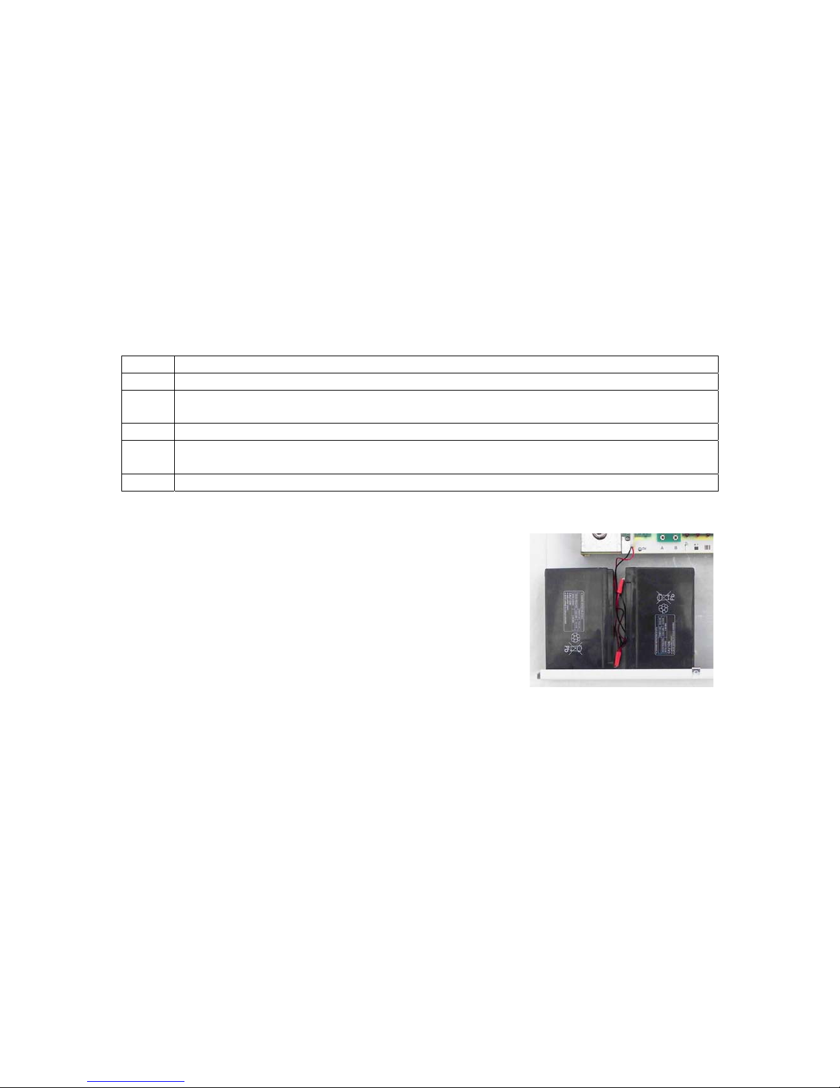
6 Fit the battery(s) into the lower half of the case. (See below).
The Dycon Sentient D4800 can take up to 4 x 7Ahr batteries.
Fit the batteries as shown.
With one pair on left (as shown) and another pair on
the right of the unit.
Connect the leads and
place batteries as shown.
See Section 14.2 regarding the battery cut-off module.
D4800 Sentient Technical Manual – D4800TM/09G/v1 9
Page 10
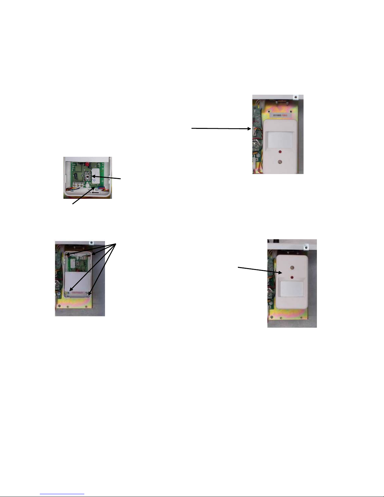
6.2 Dycon Sentient D4800 Internal PIR Set-up
The internal PIR can be configured to allow operation at different operational heights (from
floor to 2.5 meters from floor).
The PIR unit is rotated by 180 degrees and the PCB adjusted to cater for different
operational height as set out below:
Operation at 1.5 to 2.2 metres
Mount PIR in the lower position of the
chassis as shown. If Sentient to be floor
mounted then see picture below
If unit operated at greater than 2 meters in
height OR at floor level, position main PCB
in centre of slot.
If unit operated at 1.5 meters then position
PCB so that the screw is at the top of the slot
i.e. PCB moved down towards bottom edge of case...
NOTE: Leave the “Walk Test” switch ON
Operation Mounted on the Floor
4 mounting screws (with lid removed)
Mount PIR in the upper position of chassis as
shown if Dycon Sentient D4800 to be
floor mounted
Adjust the PCB so that it is in the centre of the
fixing slot (see above). This will give a nominal
12-metre detection range.
NOTE: The PIR unit is turned up-side down depending upon mounting height of main unit.
D4800 Sentient Technical Manual – D4800TM/09G/v1 10
Page 11

6.3 Dycon Sentient D4800 External Power and GSM Aerial
The Dycon Sentient D4800 can
have GSM aerial external power
and GSM aerial mounting. The
main chassis has provision to
take the connectors.
GSM aerial mounting
External power mounting
See the installation instructions
with the connectors.
6.4 NVM Fitting
The Non Volatile Memory chip (NVM) holds all the programming information (numbers
dialled, SMS text etc) If not already fitted it must be fitted into the units as shown below :-
NOTES:
1. Do not bend the pins.
2. Ensure the end with “notch” or “dot” is at the front.
3. To avoid problems with ESD (ElectroStatic
Discharge), do not place it upon any plastic surface
when removed from the unit or programming pod.
NVM chip
Fig. 4
NOTE: For full information of the NVM programming / remote programming and control see
the Dycon Sentient D4800 Downloader Manual” .
6.5 SIM Card Selection
A suitable GSM SIM Card may be obtained from your GSM Service Provider.
• The Dycon Sentient D4800 requires `Data' transmission to send signals to the ARC and for
up/downloading.
• The Dycon Sentient D4800 requires `SMS' to send SMS text to portable phones and to
receive SMS commands
• Ensure that the SIM Card is enabled for `SMS & Data' (speech is not required). The SIM
card has a number printed on it. It is recommended that this number, and the relevant
telephone and PIN numbers are recorded with the site records.
NOTES:
• Some SIM cards have a PIN number - this should also be stored with your records.
• Depending upon the SIM card supplier you may be given separate telephone numbers for
the SMS and Data numbers.
• The SIM cards supplied by DYCON (UK) are special “Data & Text” ONLY. They do not
have voice functions.
D4800 Sentient Technical Manual – D4800TM/09G/v1 11
Page 12

6.6 Fitting the SIM Card
1. Release the SIM tray by pressing the release button (on right hand side of socket) (using
small screwdriver or similar suitable tool).
2. Pull out the tray and place the SIM card in it (NOTE: it will only fit in one way).
3. Push the tray back in until it locks in position.
GSM Aerial
connection
Check orientation of tray
when re-inserting
Push in pin
to make SIM
card tray
slide out
NVM Chip
Fig. 5A Fig. 5B
6.7 Learning Detectors into the Dycon Sentient D4800 Alarm System
1. With the unit in “Standby” mode, use the A push button to select “Zone Programming”
mode. Now press the B button - a “L” will be displayed; now repeatedly press the B button
until the desired zone number is displayed (flashing).
2. Operate the `learn' trigger on the detector to make it transmit its learn signal. When the
signal is received, the displayed zone number will stop flashing and the beeper will give a
double beep-beep. That zone number will now correspond to that detector.
Radio Siren
• The Dycon radio siren can ONLY be programmed onto zone number 3
• Zone number 3 can ONLY be used for the radio siren
NOTE: If the zone number is on solid, that zone is already programmed - therefore
programming is not possible (see Section 6.8). If the number is flashing, that zone is not
programmed - programming is therefore possible.
6.8 Removing Detectors from Zones
To remove ANY detector / siren, ensure the system in standby mode:
1. Using the [A] key, go to “Zone Programming” mode.
2. Using the [B] key, scroll round to the zone number to be un-programmed.
3. Now press the [B] key for 3 seconds (beeps will be heard) - when the display starts
flashing, that zone is no longer programmed with a detector or siren.
D4800 Sentient Technical Manual – D4800TM/09G/v1 12
Page 13

6.9 Detector Types / Zone Number
Zone 1 -Entry / Final Exit Detector *
Program a PIR or universal transmitter that will operate whenever the “Entry/Final Exit” door
is opened. A detector must be associated to this zone whenever using the key switch
operation of the Dycon Sentient D4800 control unit.
Zone 2 – Entry Route *
Program a PIR or universal transmitter that will operate whenever a person moves
from the “Entry/Final Exit” door to the Dycon Sentient D4800 control unit.
Zone 3 – Siren unit
This zone can ONLY be used for the external siren unit.
Zones 4 to 15 - Any detector
These zones can be used for any Dycon compatible detector, PIR, smoke detector, handheld control etc...
NOTE *: The above assumes standard default zone programming for Zones 1 and 2.
6.10 Learn Pins
Siren
Press the “Learn” push button if fitted OR momentarily short the internal `learn' pins
(top left hand side of PCB).
PIR
Press the button on the front of the PIR just below the large white lens.
Universal Transmitter
Momentarily short the internal `learn' pins just above the terminal block.
Smoke Detector
Momentarily short the internal `learn' pins. To be found within a round hole in the base (after
removing the detector head from base unit).
Hand-held Controller
Press “Standby” and “Armed” buttons together (PA alarm).
Other Detectors
See instructions supplied with the detector.
D4800 Sentient Technical Manual – D4800TM/09G/v1 13
Page 14

7. Installing a Dycon Sentient D4800 Alarm System
7.1 Main Controller Siting
The Dycon Sentient D4800 control unit sends alarm signals on the GSM radio network.
ALWAYS do a site survey to check that there is sufficient GSM signal before installation.
Large metal structures can affect radio signals therefore, wherever possible, avoid installing
the control unit directly under metal roofs or within metal skinned buildings because this will
reduce the signal strength and may inhibit operation completely. If this is unavoidable, the
strongest signal will be found away from the metal roof or close to large external windows or
skylights.
Wherever possible do not install the control unit close (1 metre) to cable runs, ducting,
structural metalwork, metal pipes, water tank, electronic equipment, e.g. photocopiers, fax
machines etc... These can have similar effects as metal roofs.
Reliable operation is unlikely with low signal strength. If the display indicates a low signal
strength, it should be improved by moving the control unit or fitting an external GSM aerial.
Often a move of a few centimetres can make a difference.
7.2 Site Survey GSM
You can use the Dycon Sentient D4800 control unit to survey the proposed site for a GSM
signal.
1. Put the control unit key switch in the “Standby” position
2. Connect the battery(s) in the control unit.
3. Wait for the initial power up routine (approximately 30 seconds).
4. When the control unit GSM Signal LED 1 is lit, the display will show the received
GSM signal strength. Carry the control unit around the site. Select the point where
the highest number (highest signal strength) is displayed (See Section 13).
You can also use a portable GSM telephone to show GSM signal strength. It MUST
use the same GSM network as the Dycon SIM card uses. The signal shown on the
mobile phone should be at least half the maximum signal that can be obtained. A
portable GSM telephone that uses a different GSM network will NOT show the
correct signal strength.
The location chosen for the Dycon Sentient D4800 control unit must:
• Have adequate GSM signal strength (reading of 4 minimum)
• Be within the area to be protected (to give protection to the control unit)
• Receive signals from all the system detectors.
Make a note of the location chosen and use it when installing the control unit.
Take care when handling and transporting the Dycon Sentient D4800 control unit with the
batteries fitted, the unit can be heavy.
NOTES:
a) The site should also be surveyed for “Background Radio Noise”. See Section 7.4
b) (UK) The Dycon Sentient D4800 can be fitted with T30 / T40 Fastfix screws
D4800 Sentient Technical Manual – D4800TM/09G/v1 14
Page 15

7.3 External Aerial
An external aerial is available for use with the Dycon Sentient D4800 control unit. This
should only be used when it is impossible to locate the control unit at a point of suitable
To connect / fit an external aerial, see the instructions that come with the aerial pack.
NOTE: The Dycon Sentient D4800 needs an internal conversion kit in addition to the aerial.
7.4 Radio Background Noise Test
1. Ensure that the control unit has its batteries disconnected and the key switch is in the
“Standby” position.
2. Site the control unit within the protected area and where it can receive signals from all of
its detectors. The control unit's location must also have an adequate GSM signal strength.
See Site Survey, section 3. A location towards the centre of the protected area and high is
recommended.
3. With the main controller located in its final position, connect the batteries. First check that
the GSM signal strength is 4 or higher.
4. Then using the [A] button select “Walk test”. Use the [B] button to clear the display to a
small “o”.
5. The control unit should be left for at least 5 minutes whilst other work is done. DO NOT
ACTIVATE ANY PERIPHERAL DEVICES.
6. After 5 minutes check that the display still shows a small “o”.
7. If the display shows “RO” then the background radio noise is too high. In this case try resiting the Dycon Sentient D4800 control unit (ensuring the GSM signal is still ok) OR
alternatively the Dycon Sentient D4800 controller can be remotely re-programmed to
overcome the background noise. Repeat from step 4 above in new position.
8. DO NOT TRY AND COMMISSION A SITE WHEN “RO” IS DISPLAYED IN WALK TEST
MODE (See sections 8.3 and 10).
7.5 Installation of Detectors
NOTES
1. Install a detector at the “Entry / Final Exit” door. Install a detector on the path between the
“Entry / Final Exit” door and the Dycon Sentient D4800 control unit. Site other detectors as
required.
2. Ensure that the PIR detectors are located so as to detect human movement in the
desired areas. Test the operation of the system. See Sections 8.2 and 8.3
D4800 Sentient Technical Manual – D4800TM/09G/v1 15
Page 16

7.6 Radio Siren Unit Siting
The Dycon siren unit is designed for use within the protected premises. The unit is protected
from dripping water when installed upright on a wall.
1. Install the siren unit within the protected area in a location away from the Dycon
Sentient D4800 control unit and where it may be easily seen and heard.
2. It is possible to connect any type of wired detector to the alarm input terminals in a
siren unit. See Other Detectors.
7.6.1 Sire Tamper Inputs
The siren unit has been designed to allow the use of a lid and wall tamper detection.
However, it may not always be possible to have the wall tamper active - in this case the siren
can be set up to only work with the lid tamper input.
Above the terminal block (bottom edge of PCB) there are 3 sets of 2 pin connecters.
The bottom two sets of pins should be used when both the lid and wall tamper detection
switches are in use (wires may be plugged on in any order).
If only the lid tamper detection switch is being used then the wires from the lid tamper should
be plugged onto the top set of pins only.
(To access remove lid of inner black box)
“LEARN” push button Tamper selection pins
Fig. 7 Fig. 8
NOTE: Some units may have a pair of “Learn” pins.
D4800 Sentient Technical Manual – D4800TM/09G/v1 16
Page 17

7.7 PIR Detector
The PIR as standard has a detection range of 12 meters when mounted 2 meters high, with
an angle of view of 90 degrees.
• DO mount so that possible intruders walk across the front of the unit and not
towards it.
• DO NOT mount with the lens facing windows, sources of heat i.e. radiators,
boilers etc.
• DO NOT place where drafts can be produced within the detection range.
PIR mounted on Dycon Quick Fix bracket
Lens
Test / Learn button and LED
Fig. 9
7.7.1 Preparing a Dycon PIR Movement Detector for use
1. Partly remove the screw securing the cover.
2. Unclip the lid and lens assembly from the case rear
3. Programme links as required (see following section).
4. Fit two AA cells in the socket, ensuring they are fitted correctly.
5. Replace the lid and lens assembly to the case rear
6. Replace the cover securing screw.
7.7.2 Dycon PIR Link Setting
The PIR has three programming links which function as set out below.
The links are located underneath the battery holder (aerial pointing upwards on the right).
They are numbered 1, 2, 3 left to right.
Fig. 10
D4800 Sentient Technical Manual – D4800TM/09G/v1 17
LINKsettingpins
Orderasseeninphoto123
Page 18

Dycon PIR Link Setting (continued)
Pulse Count
A PIR works by detecting movement through its detection beam pattern and producing
“Detection Pulses”. The number of pulses required before an alarm is generated can be
programmed.
Program Links Number of Pulses for an Alarm
NO LINKS FITTED - 4 Pulse
Link No 1 Fitted - 2 Pulses
Link No 2 Fitted - 8 Pulses
NOTE: The above links are not affected by Link No 3.
Radio / PIR Transmission Inhibit
To increase the battery life of the detector the radio transmissions can be controlled.
Link No 3 NOT fitted
After the PIR has transmitted a alarm condition, the PIR and transmitter is inhibited for 2
minutes after the “Last” time movement is detected – e.g. if someone is walking about for 20
minutes then a new radio transmission will not occur until 22 minutes after the initial
detection.
Link No 3 Fitted
With this link fitted, the PIR will allow further radio transmissions after 2 minutes under all
conditions – e.g. in the above example movement for 20 minutes will cause the unit to
transmit alarm information 10 times.
7.8 Universal Transmitter
It is possible to connect any type of wired detector to a universal transmitter. See Other
Detectors below. The universal transmitter may even be mounted within a detector,
providing there is sufficient space and its case is not metal.
REMOVE LINK IF USING
EXTERNAL MAGNET
WITH INTERNAL
REED SWITCH
Learn Pins Tamper Loop
Short to Learn Alarm Loop
Wire the external detector or contacts into the terminal block. Remove the ex-works links
only if external wiring is used.
D4800 Sentient Technical Manual – D4800TM/09G/v1 18
Page 19

7.9 Smoke Detector Siting
• These should normally be mounted at the centre of ceilings.
• DO NOT mount in corners.
• Refer to the data sheet supplied with the smoke detector for installation information.
7.10 Other Detectors
Se the information instructions supplied with the detector.
8. Functional Testing of a Dycon Sentient System
8.1 Basic Test Set Up / GSM Communication Tests
Test the NVM, SIM card and the alarm reporting functions of the control unit.
Ensure you have informed your ARC that you are ready to test your Dycon Sentient D4800
unit.
1. Open the control unit lid. Ensure that the key switch is in the “Standby” position.
2. Power up the control unit by connecting one or two batteries to their sockets. The unit
will initialise.
3. If the NVM is an incorrect type, is faulty, fitted incorrectly or has been incorrectly
programmed, the Test LED will flash rapidly.
4. If there is a problem with the SIM card or the GSM radio module, the GSM Signal
LED will flash rapidly.
5. Initialisation will take 30 seconds. At the end of this period, the GSM signal LED will
be lit and the display will show the received GSM radio signal strength. See Section
13.
6. Test the GSM reporting path to the ARC. Press the [A] or “Select” button until the
Test Call LED 5 is lit. Press the [B] or “Apply” button to send a test signal to the ARC.
When SMS messages have been programmed in the NVM, these will be sent to the
portable phones after the ARC transmission.
7. The display will show a large “C” when transmissions to the ARC are active.
8. The display will show a small “c” when SMS transmissions are active.
9. Contact the ARC to confirm that the test was successful.
10. See the display on the relevant portable phones for the SMS messages.
11. Check the background radio noise. See Section 7.4.
12. Your Dycon Sentient D4800 control unit is now ready to have detectors associated
with it. See Section 6.7
8.2 Functional Testing
Functional testing of a Dycon Sentient D4800 system is conducted with the unit upright, in its
normal operating condition. Functional testing will ensure that all the detectors are working
and that the radio communication within the installation is satisfactory.
1. Test the control unit battery. Press the [A] or “Select” button until the BATT Test LED
2 is lit. The display will indicate the control unit's battery voltage (see section 13 for
actual voltage). If low, place the unit on charge.
2. Press the [B] or “Apply” button to `load test' the battery. Observe the display. Ensure
that the display number stays stable or reduces by one. A drop of 2 or more
indicates a weak battery. If the battery is weak, place the unit on charge or change
the battery(s) for fully charged batteries.
D4800 Sentient Technical Manual – D4800TM/09G/v1 19
Page 20

Functional Testing (continued)
3. Learn all the detectors into the control unit (see Section 6.7).
4. Install all the external detectors into their final position.
5. To test each detector. Press the [A] or “Select” button until the WALK Test LED 4 is
lit. The display will show a small “o”.
6. Trigger each detector in turn and open each unit to cause a tamper alarm. As each
signal is received from the detector its zone number will be displayed followed by a
large A for an alarm signal, or a small t for a tamper signal.
7. NOTE: The “first” time each zone goes into alarm condition, the control unit sounder
will pulse. This will give clear audible indication of detection (the sounder will only go
once for each zone). To re-activate the sounder in Walk test mode, exit walk test (by
using the [A] button) then go back into walk test mode.
8. Repeat until signals from all detectors have been confirmed. When several detectors
have been activated, the display will cycle through those detector numbers showing
A = alarm and t = tamper.
9. E.g. display A5 t5 A1 = Alarm on zone 5, Tamper on zone 5 and Alarm on zone 1.
NOTE: see Section 8.3 below.
10. Press the [B] or “Apply” button to clear the display to a small “o”.
11. If the detectors are installed in protected premises ensure that their detection area
and range is as required.
12. See “Controller Installation” for background radio noise testing (see Section 7.4).
8.3 Peripheral Detector Signals
When in “Walk Test” mode the display will normally show “A” followed by the zone number.
However, if the zone number is followed by a “R” then this indicates that the radio signal
from the detector is too low. In this case, the detector has to be re-sighted (closer to the
Dycon Sentient D4800 controller) or the radio signal level will have to be changed.
To have the radio level re-programmed, contact the Dycon depot or distributor.
NOTES:
• Adjusting the radio signal level lower may cause background noise problems,
depending on the initial settings.
• Increasing the jamming level will reduce the achievable radio range that the detectors
will work at.
D4800 Sentient Technical Manual – D4800TM/09G/v1 20
Page 21

8.4 Alarm Test Calls
1. Fit the lid and use all 3 securing screws to hold the lid in place.
2. Set the system by moving the control unit key switch to the “Armed” position. After
the exit time is complete, the system will go to the armed state. An `Armed'
transmission will be sent to the ARC (and by SMS to mobile phones).
3. Generate an alarm by triggering a detector. If programmed, the siren will sound.
Alarm transmissions will be sent to the ARC (and by SMS to mobile phones).
4. Unset the system by moving the control unit key switch to the “Standby” position. The
system will go to the standby state. A standby transmission will be sent to the ARC
(and by SMS to mobile phones (system unset).
5. Contact your ARC to confirm that all signals have been received, e.g. Armed, Alarm,
Standby etc...
6. The tests are complete. The Dycon Sentient D4800 System is now charged, fully
tested and is ready for use.
7. Ensure that the control unit key switch is left in the “Standby” position and that the lid
lock is used (if fitted).
8.5 Siren Test
The siren may tested by turning the key switch to “Armed” and pressing the [B] button for 3
seconds. The siren should start. To stop the siren, turn the key switch back to “Standby”.
8.6 Mains Supply
The Dycon Sentient D4800 control unit has provision for an external power supply (a fitting
kit is required). This power supply may be a charger used short term, or alternately may be a
“Trickle” charger which is left continually connected.
If the Dycon Sentient D4800 has a trickle charger connected it may be programmed to
transmit a “Mains Fail” signal in the event that this trickle charger stops supplying power for
any reason. The transmission of the “Mains Fail” signal will be delayed by a random time of
1 to 20 minutes.
9. Operation Zone Supervision
The detectors used automatically transmit a supervision signal approximately every 20
minutes. If the Dycon Sentient D4800 fails to receive a supervision signal from a
programmed detector for a period longer than 80 minutes, it will transmit a zone supervision
signal (if programmed in the NVM). The cause of the received supervision signal should
always be investigated.
10. Radio Signals
Radio Interference and Jamming
The detectors, hand-held controller and the siren unit use radio signals to communicate with
the control unit. There is always a possibility that other users of the same radio frequency in
the local area may disrupt or cause interference to the communications between the Dycon
units, e.g. several Dycon systems that are all operating in the same radio local area.
Occasional interference is to be expected and the Dycon Sentient D4800 system uses
advanced error detection and correction software to overcome these radio effects so that no
untoward operational effects will be seen.
D4800 Sentient Technical Manual – D4800TM/09G/v1 21
Page 22

Where interference is very severe or continuous transmissions are coming from other users,
these transmissions can cause `jamming' of the radio frequency. Jamming can stop Dycon
units communicating.
10.1 Jamming
When the Dycon Sentient D4800 is in “Armed” mode it will monitor the background radio
noise. It will average the noise over 4 minutes (programmable). If the background noise
becomes too high, it will send a jamming report to the ARC and by SMS. This will give
warning of possible loss of security due to radio noise.
11. SMS - the GSM Short Message Service
Service provided by companies supplying a GSM communications system where a short text
message may be sent to (and from) GSM phones and read on the GSM phone display.
Messages are sent via a Message Centre.
11.1 SMS Alarm Reporting
In addition to sending alarm signals to a ARC via the GSM radio path, the Dycon Sentient
D4800 system can also send SMS (Short Message Service) text messages to 1 or 2 GSM
mobile phones and/or pagers.
These text messages may be used to report an alarm event to other people, e.g. the
premises key holder or owner, an alarms installation engineer etc...
The text message(s) are programmed into the control unit NVM and can identify the site, the
detector that was triggered and alarm, restore, setting or unsetting events. Monitoring
messages can also be sent, e.g. low battery warning. See the ARC Reporting list. Refer to
the Dycon downloader programming and downloading manual for full SMS programmable
options.
12. SMS Remote Control
Operation - Controlling the Dycon Sentient D4800 System using SMS Commands
The Dycon Sentient D4800 system may be armed or returned to the standby state remotely
by sending an SMS message to it from a mobile phone. In addition, the current state can be
requested and the operation of the internal siren can also be controlled.
NOTE: When `Low Power Mode' is selected, SMS operation may be delayed by up to 90
minutes depending upon the NVM programming.
To provide security, a 6-digit access number must always be used when sending any SMS
command. The security number is programmed into the NVM
NOTE: Ensure that the phone being used to control the Dycon Sentient D4800 system has
its caller ID switched on. This will allow confirmation messages to be sent back.
To remotely arm a Dycon Sentient D4800 system, send the following text message:
<The 6 digit Security Access Number> <Space> <SET>
or
<The 6 digit Security Access Number> <SET>
D4800 Sentient Technical Manual – D4800TM/09G/v1 22
Page 23

12. SMS Remote Control (cont’d)
Remote Disarming
To remotely unset a Dycon Sentient D4800 system, send the following text message:
<The 6 digit Security Access Number> <Space> <UNSET>
or
<The 6 digit Security Access Number> <UNSET>
Reducing Siren Time
To reduce the bell delay to 0, send the following text message:
<The 6 digit Security Access Number> <Space> <BELL>
e.g. 237118 BELL
Inhibit Low Power Mode for 30 minutes
This command puts the Dycon Sentient D4800 control unit on full power and allows
up/downloading to operate during a 30-minute period. Send the following text message:
<The 6 digit Security Access Number> <Space> <TIMEOUT>
or
<The 6 digit Security Access Number> <TIMEOUT>
Resume Low Power Mode
This command returns the Dycon Sentient D4800 control unit to the “Low Power” mode after
the above 30-minute command has been used. Send the following text message:
<The 6 digit Security Access Number> <Space> <RESUME>
or
<The 6 digit Security Access Number> <RESUME>
NOTES:
1. When an incorrect 6-digit security access number is used, there will be no action.
2. When a correct 6-digit security access number is used followed by an incorrect
command, an “Invalid Command” message will be sent to the sending GSM mobile
phone.
12.1 Remote Control GMS / SMS
When the Dycon downloader programming software is used on a PC with a modem, it is
possible to arm and disarm a Dycon Sentient D4800 system. It is also possible to make the
control unit send a `Test' message by GSM to the ARC and to SMS phones.
For full details of the Dycon Downloader operation, refer to the Dycon downloader manual.
D4800 Sentient Technical Manual – D4800TM/09G/v1 23
Page 24

12.2 Remote State Query
To remotely interrogate a Dycon Sentient D4800 system to determine the “Armed/Disarmed”
state, send the following text message :
<The 6 digit Security Access Number>
e.g. 237118
The Dycon Sentient D4800 control unit will then send a corresponding “Armed” or “Standby”
signal to the ARC and/or an SMS “Set” or “Unset” message.
13. GSM and Battery Strength Indications
GSM Signal
With the key switch in the “Standby” position, press the [A] or “Select” button until the GSM
Signal LED 1 is illuminated. The display will show a number indicating the received GSM
radio signal strength.
9 = Maximum GSM radio signal strength
8 = Strong
7 = Good
6 = OK
5 = Low
4 = NOTE Minimum acceptable GSM radio signal strength
3 = Weak
2 = Very weak
1 = Very weak
0 = No GSM signal detected
Battery Test
With the key switch in the “Standby” position, press the [A] or “Select” button until the BATT
Test LED2 is illuminated. The display will show a number indicating the battery voltage.
9 = 13.8 volts - Fully charged.
8 = 13.5 volts
7 = 13.2 volts
6 = 12.9 volts
5 = 12.6 volts - Charge required
4 = 12.3 volts - Charge required
3 = 12.0 volts - Charge required
2 = 11.7 volts - Charge NOW
1 = 11.4 volts - Charge NOW
0 = 11.1 volts - Empty, Charge NOW
Press the [B] or “Apply” button to place a heavy load on the battery. If the voltage reading
drops by 2 or more on the display, the battery capacity is below standard and the battery(s)
both require replacing.
D4800 Sentient Technical Manual – D4800TM/09G/v1 24
Page 25

14. Battery Fitting
The Dycon Sentient D4800 units can take between one and four batteries. These should be
Sealed Lead Acid 12 volt 7 Amp/hour capacity (94 x 150 x 65 mm (H x L x W).
NOTE: Some Dycon Sentient D4800 versions are fitted with a “D” cell battery pack adaptor.
In these units, 8 or 16 Alkaline D cell batteries should be used I.E. Duracell, Procell etc...
1. Ensure that the key switch is in the “Standby” position.
2. Ensure that no power supply is connected to the control unit.
3. Connect a battery lead assembly to each battery. These are supplied in the fitting kit
that is inside the Dycon Sentient D4800 control unit when new.
4. Fit the battery(s) in the lower half of the case.
5. Refer to the preparation notes for connection and testing instructions.
NOTE: Take great care when handling and fitting batteries. They are heavy and an electrical
short-circuit at the battery terminals can be dangerous.
14.1 Deep Discharge Damage
Deep discharge means that the battery voltage has fallen below 10 volts. During deep
discharge, there will be insufficient power to operate the unit and alarm signals will not be
sent to the ARC and/or an SMS message sent to a mobile phone(s).
Normal Sealed Lead Acid (SLA) batteries should not be allowed to go into deep discharge. If
they do then there storage capacity will be greatly reduced.
14.2 Dycon Sentient D4800 Battery Cut Off Module
The Dycon Sentient D4800 has a plug on reset module which is used to protect the unit, and
also to stop deep discharge of the batteries. This module has three settings which allow the
use of different types of battery.
Fitting
If the module
becomes unplugged,
it must be fitted
as shown.
The module plugs onto the top 4 pins
Setting
A. Jumper on 2 and 3 9.5/10V for sealed lead
acid batteries
B. Jumper on pins 1 & 2 8.4 / 9V
C. Jumper parked on spare pin 7.5/8V for
Alkaline batteries.
NOTE: Pin 1 at top
A B C
D4800 Sentient Technical Manual – D4800TM/09G/v1 25
Page 26

14.3 Battery Recharging
Power Supply and Batteries
The Dycon Sentient D4800 control units may be fitted with up to 4 x 13.8 volt rechargeable
lead-acid gel batteries. The siren unit uses one 13.8 volt rechargeable lead-acid gel battery.
A separate battery charge should be used to charge the batteries – alternately, a plug in
trickle charger could be used (contact Dycon for information).
14.4 Low Battery Reporting
During use, all Dycon Sentient D4800 units use power from their internal batteries. When the
battery voltage falls to the `Low Battery Voltage' limit, the Dycon Sentient D4800 will send a
`low-battery' signal to the ARC and/or an SMS message. When the `low battery' signal is
received, the batteries in the control unit and/or siren unit should be recharged.
Batteries in all other units are not rechargeable. These batteries should be replaced with
new. “Low battery” reports from detectors will identify the individual detector with a low
battery condition.
15. Remote Programming of the Dycon Sentient
In some cases the Dycon Sentient D4800 will have to be remotely programmed for such
things as SMS text, radio jamming signals, “Exit / Entry” times etc...
If a technician is at the site, he is to switch the Dycon Sentient D4800 panel to the “Armed”
position, then press the [A] button for 3 seconds, then return the key switch to standby. This
puts the Dycon Sentient D4800 unit in “Online” mode for 30 minutes to receive remote
programming.
Alternatively, an SMS command can be sent (depending upon programming). When an
upload is sent, the Dycon Sentient D4800 will go into its power up routine (as if the power
has just been applied). When this is over, the Dycon Sentient D4800 has been reprogrammed.
16. Dycon Sentient Product Changes
16.1 DYCON Software Version
The software version of the Dycon Sentient D4800 alarm is shown during initial power up.
Approximately 3 seconds after applying power, the display will show 4 numbers in sequence.
These 4 numbers are the software version.
D4800 Sentient Technical Manual – D4800TM/09G/v1 26
Page 27

17. Troubleshooting
Q. What if the GSM signal has not been received by the Alarm Receiving Centre?
Check that the NVM is fitted has been correctly programmed, e.g. site code, gateway
number, ARC NUA numbers.
Check that the SIM card is fitted has been correctly programmed, i.e. it is enabled for `Data'.
Check, using the signal strength indication or a suitable portable phone that the radio signal
is sufficient and the GSM path status = OK.
Check with a meter that the voltage at the battery terminals is 12v or more and does not dip
when the control unit is signalling.
See Appendix 1 for GSM fault indications. These will help diagnose radio path problems.
Q. What if the SMS Message has not been received by the mobile phone(s)?
Check that the NVM is fitted has been correctly programmed with the speech or SMS
number of the mobile phone(s).
Check that the SIM card is fitted has been correctly programmed.
Check, using the signal strength indication or a suitable portable phone that the radio signal
is sufficient and the GSM path status = OK.
Check with a meter that the voltage at the battery terminals is 12v or more and does not dip
when the Dycon Sentient D4800 control unit is signalling.
Ensure that the mobile phone can receive SMS messages by using it to send an SMS
message to itself. See Appendix 1 for GSM fault indications. These will help diagnose radio
path problems.
Q. What if the SMS Messages from the mobile phone(s) do not control the Dycon
Sentient D4800 System?
Check that the NVM is fitted has been correctly programmed.
Check that the SIM card is fitted has been correctly programmed to receive SMS messages.
Check, using the signal strength indication or a suitable portable phone that the radio signal
is sufficient and the GSM path status = OK.
Check with a meter that the voltage at the battery terminals is 12v or more and does not dip
when the control unit is signalling.
Ensure that the portable phone can send SMS messages by using it to send an SMS
message to itself.
Check that you are using the correct access code.
Check the number that is receiving the SMS messages is correct
D4800 Sentient Technical Manual – D4800TM/09G/v1 27
Page 28

NOTE: When `Low Power” mode is selected, SMS control will be delayed until the Dycon
Sentient D4800 control unit next `powers-up' and monitors the GSM radio network. See
Appendix 1 for GSM fault indications. These will help diagnose radio path problems.
Q. I get “RO” or “A No R” in Walk Test
Your signal received from an individual detector is low (“AR No”) OR the background radio
noise is too high (for both see Section 7.4).
“RO” Background radio noise high
“A No R” (displayed in sequence) (A = alarm, No = Zone number, R = radio signal received)
D4800 Sentient Technical Manual – D4800TM/09G/v1 28
Page 29

APPENDIX 1
LED Indications
NOTES
There are two basic states for the Dycon Sentient D4800 alarm: system armed and system
in standby.
When the system is in standby, the LEDs indicate the system mode.
1. ‘something’ = flashing display
2. <Zone> = Zone number 1 to 6
3. The lid has to be removed for the display to be visible.
LED Display (7 Seg) State - Meaning
Unset Mode
GSM - Unset / system Initialising
GSM Number 0 - 9 GSM signal strength
GSM C GSM communication in progress
‘GSM’ 0 or 1 GSM fault
BAT Number 0 - 9 Battery load test passed
‘BAT’ Number 0 - 9 Batteryload test failed or not done
CODE L Code learn mode
CODE Number <zone> Radio zone learnt (programmed)
CODE ‘Number <zone’ Radio zone not learnt (un-programmed)
WALK A <zone> Alarm zone/s activated
WALK Small t <zone> Tamper on zone/s
WALK Small b <zone> Zone/s with low battery
WALK Small r <zone> Zone radio level POOR
WALK Small o All zones clear
‘WALK’ Radio carrier detected
TEST Small t Test call enabled (press A)
‘TEST’ NVM fault
ARMED MODE (low power debug mode)
GSM System initialising (after low power mode)
GSM Large C GSM communication in progress
GSM Small c SMS communication in progress
Large S System armed (shown for 5 seconds after lid
opened)
Large E Entry / exit (shown for 5 seconds after lid
opened)
F Exit fault
‘A’ Alarm state
FTA First To Alarm
Large A <zone> Indicates FTA zone
Small t <zone> Indicates FTA Tamper
Small b <zone> Indicates Low Battery
Large S <zone> Supervision FTA
Large J <zone> Indicates FTA jamming
Small r <zone> Indicates low radio signal
D4800 Sentient Technical Manual – D4800TM/09G/v1 29
Page 30

APPENDIX 2
y
Specification
Models D4800 D
con Sentient control unit
Dimensions (W x D x H) 433 x 90 x 410 mm (overall)
Weight 6kg (no batteries)
Mains requirement Charger dependent
Radio Path GSM
Expansion Wired NC contact into Universal TX and radio transmission
from wire-free detectors
DC Power Requirement 12.0 - 13.8volts DC, 0.1volt max ripple
DC Current Mode dependent (maximum on GSM transmit 300mA)
Hourly Battery Load Test
Current
800mA for 1/10 second (if programmed)
Low Battery 11.8-12.0 volts falling, 12.8-13.0v recovery (programming
dependant)
Tamper Detection Lid
Temperature -20C to +60 transit, -4C to +50 operating
Humidity 0 - 80% non-condensing
Mounting Any orientation - upright recommended
Warranty 12 months
Battery Life Approximately 25 days per 7Ahr Battery (dependant on
programming and use)
Siren unit 1 x 7AH BATTERY
100 days (no alarm activations)
Each alarm activation will shorten the battery life by 1 day.
D4800 Sentient Technical Manual – D4800TM/09G/v1 30
Page 31

APPENDIX 3
EEC Approvals
All components of the Dycon Sentient D4800 system carry the CE mark and meet the
requirements of EEC directives for Electromagnetic Compatibility, Electrical and Mechanical
Safety, and `licence exempt' use within the requirements and specifications of EEC
Harmonised Frequency radio bands.
International GSM Approval
The Dycon range of products incorporate an independently tested and approved GSM radio
module that meets the requirements of International radio communication standards.
The GSM Radio Module Approval Authority is: 0681
D4800 Sentient Technical Manual – D4800TM/09G/v1 31
 Loading...