

Dynon Avionics SkyView SE, SkyView HDX, SkyView Classic, SkyView Touch System Installation Manual
Page 1

SkyView SE
SkyView Classic
SkyView Touch
SkyView HDX
System Installation Guide
Document 101320-026, Revision AA
For use with Software version v15
December, 2016
Copyright © 2009-2016 by Dynon Avionics, Inc.
Permission to print this manual is granted to third parties.
Page 2

Page 3

Contact Information
Dynon Avionics, Inc.
19825 141st Place NE
Woodinville, WA 98072
Phone: 425-402-0433 - 8:00 AM – 5:00 PM (Pacific Time) Monday – Friday
Dynon Avionics Technical Support available 7:00 AM–4:00 PM (Pacific Time) Monday – Friday
Email: mailto://support@dynonavionics.com
Fax: 425-984-1751
Dynon Avionics offers a number of Internet sites for support:
http://www.dynonavionics.com – Dynon Avionics primary web site; including:
http://docs.dynonavionics.com – Current and archival documentation.
http://downloads.dynonavionics.com – Software downloads.
http://license.dynonavionics.com – Redeem SV-MAP-270, SV-SYNVIS-280, and SV-VPX-290 licenses.
http://store.dynonavionics.com – Dynon Avionics’ secure online store for purchasing all Dynon Avionics products.
http://register.dynonavionics.com – Register your Dynon Avionics product.
http://support.dynonavionics.com – Support resources.
Stay in touch with Dynon Avionics:
http://blog.dynonavionics.com – Dynon Avionics’ blog.
https://www.facebook.com/dynonavionics - Dynon Avionics is on Facebook. Please “friend” us!
http://forum.dynonavionics.com – Dynon Avionics’ Internet forum for SkyView pilots.
http://newsletter.dynonavionics.com – Dynon Avionics’ email newsletter.
https://twitter.com/dynon - Dynon Avionics is on Twitter!
Training
http://www.dynonavionics.com/videos – Video training, including short vignettes on specific operations.
http://www.dynonavionics.com/training – Hands-on training at various events.
Copyright
2009-2016 Dynon Avionics, Inc. All rights reserved. No part of this manual may be reproduced, copied, transmitted, disseminated or stored in
any storage medium, for any purpose without the express written permission of Dynon Avionics. Dynon Avionics hereby grants permission to
download a single copy of this manual and of any revision to this manual onto a hard drive or other electronic storage medium to be viewed for
personal use, provided that such electronic or printed copy of this manual or revision must contain the complete text of this copyright notice
and provided further that any unauthorized commercial distribution of this manual or any revision hereto is strictly prohibited.
Information in this document is subject to change without notice. Dynon Avionics reserves the right to change or improve its products and to
make changes in the content without obligation to notify any person or organization of such changes. Visit the Dynon Avionics website
(www.dynonavionics.com) for current updates and supplemental information concerning the use and operation of this and other Dynon
Avionics products.
Page 4

iv SkyView System Installation Guide - Revision AA
Limited Warranty
Dynon Avionics warrants this product to be free from defects in materials and workmanship for three years from date of shipment. Dynon
Avionics will, at its sole option, repair or replace any components that fail in normal use. Such repairs or replacement will be made at no charge
to the customer for parts or labor performed by Dynon Avionics. The customer is, however, responsible for any transportation cost and any
costs that are incurred while removing, reinstalling, or troubleshooting the product. This warranty does not cover failures due to abuse, misuse,
accident, improper installation or unauthorized alteration or repairs.
THE WARRANTIES AND REMEDIES CONTAINED HEREIN ARE EXCLUSIVE, AND IN LIEU OF ALL OTHER WARRANTIES EXPRESSED OR IMPLIED,
INCLUDING ANY LIABILITY ARISING UNDER WARRANTY OF MERCHANTABILITY OR FITNESS FOR A PARTICULAR PURPOSE, STATUTORY OR
OTHERWISE. THIS WARRANTY GIVES YOU SPECIFIC LEGAL RIGHTS, WHICH MAY VARY FROM STATE TO STATE AND IN COUNTRIES OTHER THAN
THE USA.
IN NO EVENT SHALL DYNON AVIONICS BE LIABLE FOR ANY INCIDENTAL, SPECIAL, INDIRECT OR CONSEQUENTIAL DAMAGES, WHETHER
RESULTING FROM THE USE, MISUSE OR INABILITY TO USE THIS PRODUCT OR FROM DEFECTS IN THE PRODUCT. SOME STATES AND COUNTRIES
DO NOT ALLOW THE EXCLUSION OF INCIDENTAL OR CONSEQUENTIAL DAMAGES, SO THE ABOVE LIMITATIONS MAY NOT APPLY TO YOU.
Dynon Avionics retains the exclusive right to repair or replace the instrument or Software or offer a full refund of the purchase price at its sole
discretion. SUCH REMEDY SHALL BE YOUR SOLE AND EXCLUSIVE REMEDY FOR ANY BREACH OF WARRANTY.
These instruments are not intended for use in type certificated aircraft at this time. Dynon Avionics makes no claim as to the suitability of its
products in connection with FAR 91.205.
Dynon Avionics’ products incorporate a variety of precise, sensitive electronics. SkyView products do not contain any field/user-serviceable
parts. Units found to have been taken apart may not be eligible for repair under warranty. Additionally, once a Dynon Avionics unit is opened
up, it is not considered airworthy and must be serviced at the factory.
Dynon Avionics Returns and Warranty web page can be found at http://support.dynonavionics.com.
Page 5
SkyView System Installation Guide - Revision AA v
Changes in this Revision
Revision
Revision Date
Description
Revision History for previous revisions is located in
Appendix I: SkyView System Installation Guide Revision History.
AA
December, 2016
Improvements:
o Corrected table of contents missing links
o Corrected misc. formatting issues
o Updated Table 75 adding missing transponder harness wire colors
Z
October, 2016
Document number changed to 101320-025, Revision Z
New products:
o SkyView SV-HDX800 display
o SkyView SV-HDX1100 display
o ADS-B (UAT) Antenna – Rod type (978 MHz)
o Transponder antenna – Rod type (1090 MHz)
o SV-MAP-270 included with new SkyView displays and SkyView HDX
(Section 6)
New features:
o Weight and Balance (Setup)
o Maintenance Log (Setup)
o Ability to change label “CHT” to “CLNT”
o Ability to change aural message “Cylinder Head Temperature” to
“Coolant Temperature”.
Software changes in SkyView Software v15.0.0, released 2016-10-18.
o SkyView SV-HDX800 display (new product)
o SkyView SV-HDX1100 display (new product)
o SV-BAT-320 charging algorithm improved to be able to charge units
that are in protection mode.
Documentation improved in this revision:
o Section 4 – Added connection and configuration instructions for GNC
255 COM/NAV radio.
o Section 5 – Corrected incorrect references to Figures on different
AOA/Pitot Probes
o Section 7 – Updated references to use of dual SV-EMS-220/221
modules to monitor large engines or dual engines is only supported in
SkyView Classic (not SkyView SE or SkyView HDX [as of Software
v15.0])
o Section 7 – Added mention of SV-NET-SPL for use with dual SV-EMS-
220/221 installations.
o Section 7 – Added lists of all available and recommended Dynon
Avionics engine sensor kits.
o Section 11 – Added detail about the permissible use of SV-XPNDR-262
after 2020 (outside Class B and Class C airspaces)
o Section 13 – Explanation that to monitor operation of VPX, one
display must include an SV-BAT-320 or be powered independently of
the VP-X.
o Section 16 – Added alternate method for adjusting Microphone Gain
of SV-COM-C25.
o 579 pages
Table 1 – Changes in this Revision of SkyView Classic / SkyView SE / SkyView HDX System Installation Guide
Page 6

Page 7

SkyView System Installation Guide - Revision AA vii
Table of Contents
Contact Information ..................................................................................................................................................... iii
Copyright ...................................................................................................................................................................... iii
Limited Warranty .......................................................................................................................................................... iv
Changes in this Revision ................................................................................................................................................ v
1. Introduction 1-1
Warning ...................................................................................................................................................................... 1-2
Dynon Avionics Product Registration ......................................................................................................................... 1-2
About this Guide ......................................................................................................................................................... 1-3
Semantics of “Software” vs “Software” ...................................................................................................................... 1-4
SkyView Classic, SkyView Touch, SkyView SE, and SkyView HDX ............................................................................... 1-4
Special Light Sport Aircraft (S-LSA) Considerations with SkyView .............................................................................. 1-4
Getting Started ........................................................................................................................................................... 1-5
2. System Planning 2-1
SkyView units cannot / should not be mixed ............................................................................................................. 2-1
9-pin D9F and D9M Connectors are SkyView Network (not RS-232 Serial) ............................................................... 2-2
SkyView Network is a “Party Line” ............................................................................................................................. 2-2
External Switches and Indicators ................................................................................................................................ 2-3
SkyView Display Resolution ........................................................................................................................................ 2-3
SkyView System Maximum Number of Displays ........................................................................................................ 2-3
Power Specifications ................................................................................................................................................... 2-4
Major Unit Physical Specifications .............................................................................................................................. 2-6
Temperature Specifications ........................................................................................................................................ 2-7
General System Installation Tips ................................................................................................................................ 2-8
SkyView System Can Be On During Engine Start ........................................................................................................ 2-8
Installing SkyView in an IFR-Equipped Aircraft ........................................................................................................... 2-8
Mounting Requirements............................................................................................................................................. 2-9
SkyView System Construction .................................................................................................................................... 2-9
Example SkyView Systems ........................................................................................................................................ 2-13
HSI Requirements ..................................................................................................................................................... 2-17
3. Basic SkyView Display Operation 3-1
Screen Synchronization .............................................................................................................................................. 3-1
Display Bezel Layout ................................................................................................................................................... 3-2
Joystick and Button Operation ................................................................................................................................... 3-3
SkyView Touch – Touch Interface Features Not Used in Setup Menus ...................................................................... 3-5
Menu Navigation ........................................................................................................................................................ 3-6
Basic Display Operation Procedures ........................................................................................................................... 3-7
In Flight Setup Menu .......................................................................................................................................... 3-9
SETUP MENU .................................................................................................................................................... 3-10
SYSTEM EVENT Menu ....................................................................................................................................... 3-10
SYSTEM SOFTWARE Menu ................................................................................................................................ 3-11
SYSTEM SETUP Menu ....................................................................................................................................... 3-12
LOCAL DISPLAY SETUP Menu ............................................................................................................................ 3-13
PFD SETUP Menu .............................................................................................................................................. 3-14
EMS SETUP Menu ............................................................................................................................................. 3-15
MAP SETUP Menu ............................................................................................................................................. 3-15
AUTOPILOT SETUP Menu .................................................................................................................................. 3-16
TRANSPONDER SETUP Menu ............................................................................................................................ 3-16
Page 8

Table of Contents
viii SkyView System Installation Guide - Revision AA
HARDWARE CALIBRATION Menu...................................................................................................................... 3-16
Software Updates and File Operations ..................................................................................................................... 3-17
How to Update Software .................................................................................................................................. 3-18
How to Export System Settings ........................................................................................................................ 3-19
How to Load and Delete Files ........................................................................................................................... 3-19
How to Export Data Logs and Waypoints ......................................................................................................... 3-19
4. SkyView Display Installation and Configuration 4-1
Physical Installation .................................................................................................................................................... 4-2
Location Requirements for SkyView Displays ..................................................................................................... 4-2
Electrical Installation ................................................................................................................................................ 4-17
Power Input ...................................................................................................................................................... 4-17
Grounding ......................................................................................................................................................... 4-17
Airplane Master Contactor / Relay Considerations .......................................................................................... 4-17
SV-BAT-320 Connection and Operation Rules .................................................................................................. 4-17
SkyView Network Connectors .......................................................................................................................... 4-18
Network Setup and Status ................................................................................................................................ 4-18
Ethernet Connection......................................................................................................................................... 4-21
Internal Time Keeping....................................................................................................................................... 4-21
RS-232 Serial Devices ........................................................................................................................................ 4-21
USB Usage and Accessibility ............................................................................................................................. 4-32
External Dim Control (Dimming) Connections .................................................................................................. 4-33
Contact Inputs .................................................................................................................................................. 4-35
Reserved Connections for Future Use .............................................................................................................. 4-35
Display Setup ............................................................................................................................................................ 4-36
How to Access Display Hardware Information ................................................................................................. 4-36
Serial Port Configuration .................................................................................................................................. 4-36
Brightness Setup ............................................................................................................................................... 4-38
Top Bar Setup ................................................................................................................................................... 4-39
Aircraft Information .......................................................................................................................................... 4-39
SkyView Classic, SkyView SE Screen Layout Setup ........................................................................................... 4-40
SkyView HDX Display Setup / Layout ................................................................................................................ 4-41
SkyView Classic and SkyView HDX Touch Setup ............................................................................................... 4-42
Glide Ring Setup ............................................................................................................................................... 4-42
Weight and Balance Setup ................................................................................................................................ 4-42
Maintenance Log Setup .................................................................................................................................... 4-43
5. SV-ADAHRS-200/201 Installation and Configuration 5-1
Optional Components for Easier Installation of your SV-ADAHRS-200/201............................................................... 5-3
Physical Installation .................................................................................................................................................... 5-4
SV-ADAHRS-200/201 Location Requirements ............................................................................................................ 5-4
SkyView Network Connection .................................................................................................................................. 5-12
Pneumatic Ports ....................................................................................................................................................... 5-12
Compass Calibration ................................................................................................................................................. 5-13
On-ground Compass Calibration Procedure: .................................................................................................... 5-14
In-flight Compass Calibration Procedure: ......................................................................................................... 5-15
SV-OAT-340 Location and Installation ...................................................................................................................... 5-17
PFD-Related Settings ................................................................................................................................................ 5-19
Other ADAHRS Calibrations ...................................................................................................................................... 5-21
Performing Pitot/Static Checks ................................................................................................................................. 5-22
6. SV-MAP-270 Navigation Mapping License Purchase and Setup 6-1
License Information .................................................................................................................................................... 6-1
Page 9

Table of Contents
SkyView System Installation Guide - Revision AA ix
Databases ................................................................................................................................................................... 6-3
Viewing Information about Installed Databases ................................................................................................ 6-3
Terrain Database ................................................................................................................................................ 6-6
Aviation/Obstacle Databases.............................................................................................................................. 6-7
US SkyView Pilots – Stadium TFR Database ........................................................................................................ 6-8
Charts and Airport Diagrams .............................................................................................................................. 6-9
Loading Databases ............................................................................................................................................ 6-10
Removing Databases ........................................................................................................................................ 6-10
7. SV-EMS-220/221 Installation and Configuration 7-1
Physical Installation .................................................................................................................................................... 7-3
SkyView Network Connection .................................................................................................................................... 7-5
SkyView EMS Sensor Definition and Configuration Files ............................................................................................ 7-5
Engine Sensor and Transducer Planning..................................................................................................................... 7-5
Example Engine Sensor and Transducer Installations .............................................................................................. 7-20
Lycoming/Continental 4-cylinder Carbureted .................................................................................................. 7-21
Lycoming/Continental 4-cylinder Fuel Injected ................................................................................................ 7-23
Lycoming/Continental 6-cylinder Carbureted .................................................................................................. 7-25
Lycoming/Continental 6-cylinder Fuel Injected ................................................................................................ 7-27
Jabiru 2200 ....................................................................................................................................................... 7-29
Jabiru 3300 ....................................................................................................................................................... 7-31
Rotax 912 ULS Carbureted ................................................................................................................................ 7-33
Rotax 912 iS (Electronic Control Unit) .............................................................................................................. 7-35
Dual Engine Support Using Dual SV-EMS-220/221s and Two SkyView Classic Displays ................................... 7-42
Engine Sensor and Transducer Installation ...................................................................................................... 7-43
Engine Sensor Accuracy and Grounding ........................................................................................................... 7-43
Tools and Equipment Required ........................................................................................................................ 7-44
Voltmeter Inputs............................................................................................................................................... 7-44
Exhaust Gas Temperature (EGT) Sensors ......................................................................................................... 7-44
Cylinder Head Temperature (CHT) Sensors ...................................................................................................... 7-46
Tachometer ...................................................................................................................................................... 7-47
Manifold Pressure Sensor ................................................................................................................................. 7-49
Oil Pressure Sensor ........................................................................................................................................... 7-50
Oil Temperature Sensors .................................................................................................................................. 7-53
Fuel Pressure Sensor ........................................................................................................................................ 7-54
Fuel Flow Transducer ........................................................................................................................................ 7-57
Fuel Level Sensor .............................................................................................................................................. 7-59
Ammeter Shunt ................................................................................................................................................ 7-61
Carburetor Temperature Sensor ...................................................................................................................... 7-65
Rotax CHT Sensors ............................................................................................................................................ 7-65
Trim and Flaps Position Potentiometers .......................................................................................................... 7-66
Coolant Pressure Sensor ................................................................................................................................... 7-67
Coolant Temperature Sensor............................................................................................................................ 7-69
General Purpose Temperature Sensor ............................................................................................................. 7-69
Rotax 914 Air Box Temperature ....................................................................................................................... 7-70
Contacts ............................................................................................................................................................ 7-70
General Purpose Thermocouple ....................................................................................................................... 7-71
External EMS Warning Light ..................................................................................................................................... 7-72
Engine Information ................................................................................................................................................... 7-72
EMS Sensor Definitions, Mapping, and Settings ....................................................................................................... 7-74
EMS Sensor Definitions ..................................................................................................................................... 7-74
EMS Sensor Input Mapping .............................................................................................................................. 7-75
EMS Sensor Settings ......................................................................................................................................... 7-76
Page 10

Table of Contents
x SkyView System Installation Guide - Revision AA
EMS Screen Layout Editor ......................................................................................................................................... 7-85
EMS Sensor Calibration ............................................................................................................................................ 7-87
SkyView HDX ENGINE BOTTOM BAND ..................................................................................................................... 7-88
8. SV-GPS-250/2020 GPS Receiver Installation and Configuration 8-1
WAAS Data Reception ................................................................................................................................................ 8-2
Use of the SV-GPS-2020 outside the US ..................................................................................................................... 8-3
Considerations for converting an SV-GPS-250 to an SV-GPS-2020 in Special Light Sport Aircraft (S-LSAs) ............... 8-3
Physical Installation .................................................................................................................................................... 8-4
Considerations for installing an SV-GPS-2020 in an aircraft with an installed SV-GPS-250........................................ 8-6
Serial Data Connection ............................................................................................................................................... 8-7
Configuration – SV-GPS-2020 only, Serial Port 5 ...................................................................................................... 8-10
Configuration – SV-GPS-2020 (Serial Port 5) and SV-GPS-250 (Serial Port 4) ........................................................... 8-10
Testing / troubleshooting installation of the SV-GPS-250 and/or SV-GPS-2020 ...................................................... 8-11
Part 1 – Basic Serial Port Functionality ............................................................................................................. 8-11
Part 2 – GPS Receive Performance ................................................................................................................... 8-12
(US only) Additional configuration required for SDA/SIL=1… ................................................................................... 8-15
Additional Configuration Required for Compliance with FAA 2020 ADS-B Out Mandate ........................................ 8-15
9. SV-BAT-320 Backup Battery Installation 9-1
Physical Installation .................................................................................................................................................... 9-2
SV-BAT-320 Location .......................................................................................................................................... 9-2
Electrical Connection .................................................................................................................................................. 9-3
Charging the SV-BAT-320 ............................................................................................................................................ 9-3
SV-BAT-320 is Automatically Charged in Flight .................................................................................................. 9-4
Charging the SV-BAT-320 on Ground or During Aircraft Construction ............................................................... 9-4
Battery Status Icon ..................................................................................................................................................... 9-5
Detailed Battery Status Check .................................................................................................................................... 9-5
Initial SV-BAT-320 Test ............................................................................................................................................... 9-6
In the Event of Initial SV-BAT-320 Test Failure … ............................................................................................... 9-7
SV-BAT-320 Specifications .......................................................................................................................................... 9-8
Returning an SV-BAT-320 to Dynon Avionics for Exchange (Warranty Replacement) ............................................... 9-8
10. AP Servo Installation, Configuration, and Calibration 10-1
Dynon Avionics Autopilot Servo Models .................................................................................................................. 10-3
Compass Calibration Requirement ........................................................................................................................... 10-3
Additional Resources ................................................................................................................................................ 10-3
Servo Mechanical Installation ................................................................................................................................... 10-4
Autopilot Servo Calibration and Test Procedures .................................................................................................. 10-16
Autopilot Servo Initial Setup ................................................................................................................................... 10-17
Autopilot In-Flight Tuning Procedures .................................................................................................................... 10-23
11. SV-XPNDR-261/262 Installation and Configuration 11-1
Physical Installation .................................................................................................................................................. 11-3
Electrical Connections .............................................................................................................................................. 11-5
Antenna Installation ............................................................................................................................................... 11-12
Transponder-Related SkyView Display Settings ..................................................................................................... 11-16
(US only) Configuration required for SDA/SIL=1 for continued reception of ADS-B Traffic (early 2016) ............... 11-23
SkyView Systems with an SV-GPS-250 as primary GPS… ........................................................................................ 11-24
(US-Only) Equipping for compliance with FAA 2020 ADS-B Out Mandate ............................................................. 11-25
Installation of Dynon Avionics SV-GPS-2020 for compliance with FAA 2020 ADS-B Out mandate ................ 11-27
SV-XPNDR-261/262 Software Updates ................................................................................................................... 11-30
SV-XPNDR-261/262 Software Update SW02.09 ............................................................................................. 11-35
Page 11

Table of Contents
SkyView System Installation Guide - Revision AA xi
SV-XPNDR-261/262 Software Update SW02.09 Quick Decision Points.......................................................... 11-35
Deprecated SV-XPNDR-261/262 Software Update Instructions and notes .................................................... 11-37
SkyView Software v12.2 – v13.0.3 SV-XPNDR-261/262 Software SW02.06 Update ...................................... 11-38
SV-XPNDR-261/262 Software Version (SW) v2.02/v2.04/v2.06 Labeling Requirements (US Registered /
Operated Aircraft Only) .................................................................................................................................. 11-39
SkyView Software v14.0 – v14.1 SV-XPNDR-261/262 Software Update SW02.08 ......................................... 11-40
SV-XPNDR-261/262 Software Update SW02.08 Quick Decision Points.......................................................... 11-40
SV-XPNDR-261/262 Post Installation Checks .......................................................................................................... 11-41
Transponder Warnings (Transponder Self Diagnostics) ......................................................................................... 11-42
Performing Transponder Checks ............................................................................................................................ 11-43
Dynon Avionics SV-GPS-250 and SV-GPS-2020 Compliance Statements ............................................................... 11-44
12. SV-ARINC-429 Installation and Configuration 12-1
Physical Installation .................................................................................................................................................. 12-1
SkyView Network Connection .................................................................................................................................. 12-2
ARINC-429 Device Connection .................................................................................................................................. 12-2
SV-ARINC-429 Related Settings .............................................................................................................................. 12-11
13. Vertical Power VP-X Integration and Configuration 13-1
VP-X Physical, Electrical Installation and Configuration ........................................................................................... 13-1
Serial Port Connection .............................................................................................................................................. 13-2
License Information .................................................................................................................................................. 13-3
VP-X SkyView Classic Display Settings ...................................................................................................................... 13-4
Post Installation Checks ............................................................................................................................................ 13-5
14. SV-ADSB-470 Installation and Configuration 14-1
Physical Installation .................................................................................................................................................. 14-2
Electrical Installation ................................................................................................................................................ 14-4
Antenna Selection and Installation ........................................................................................................................... 14-7
SV-ADSB-470-Related SkyView Display Settings ....................................................................................................... 14-9
Post Installation Checks .......................................................................................................................................... 14-10
15. Accessory Installation and Configuration 15-1
SkyView System Angle of Attack Pitot Probe ........................................................................................................... 15-1
Encoder Serial-to-Gray Code Converter ................................................................................................................... 15-5
Capacitance to Voltage Converter for Van’s Capacitive Plates ................................................................................ 15-8
SkyView Video Input Adapter ................................................................................................................................... 15-9
SkyView Wi-Fi Adapter ........................................................................................................................................... 15-13
Advanced Flight Systems (AFS) ADVANCED Control Module (ACM) ...................................................................... 15-16
SV-BUTTON-LEVEL .................................................................................................................................................. 15-17
Pitot/Static/AOA Pneumatic Installation Kit ........................................................................................................... 15-21
Recommended Tools & Installation Accessories ............................................................................................ 15-24
Installation ...................................................................................................................................................... 15-24
Panel Module Faceplate Blank ............................................................................................................................... 15-27
SV-KNOB-DIMMER .................................................................................................................................................. 15-28
16. SV-COM-C25 Installation and Configuration 16-1
Physical Installation: SV-COM-PANEL ....................................................................................................................... 16-2
Electrical Installation ................................................................................................................................................ 16-6
Power Input ...................................................................................................................................................... 16-6
Audio Signal Grounding .................................................................................................................................... 16-6
Audio Shielding ................................................................................................................................................. 16-6
SkyView Network Connectors .......................................................................................................................... 16-6
Page 12

Table of Contents
xii SkyView System Installation Guide - Revision AA
Electrical Connections .............................................................................................................................................. 16-6
Antenna Installation ............................................................................................................................................... 16-15
SkyView System Settings for SV-COM-C25 ............................................................................................................. 16-17
Post Installation Checks .......................................................................................................................................... 16-19
Continued Airworthiness and Maintenance ........................................................................................................... 16-20
17. SV-COM-X83 Installation and Configuration 17-1
Certification Considerations ..................................................................................................................................... 17-2
Physical Installation: SV-COM-PANEL ....................................................................................................................... 17-2
Physical Installation: SV-COM-T8 .............................................................................................................................. 17-4
Electrical Installation ................................................................................................................................................ 17-7
Power Input ...................................................................................................................................................... 17-7
Audio Signal Grounding .................................................................................................................................... 17-7
Audio Shielding ................................................................................................................................................. 17-7
SkyView Network Connectors .......................................................................................................................... 17-7
Electrical Connections .............................................................................................................................................. 17-8
Antenna Installation ............................................................................................................................................... 17-16
SkyView System Settings for SV-COM-X83 ............................................................................................................. 17-19
Post Installation Checks .......................................................................................................................................... 17-20
Continued Airworthiness and Maintenance ........................................................................................................... 17-20
18. SV-AP-PANEL Installation and Configuration 18-1
Physical Installation .................................................................................................................................................. 18-3
Electrical Installation ................................................................................................................................................ 18-4
Autopilot Auto-trim .................................................................................................................................................. 18-9
Post Installation Checks ............................................................................................................................................ 18-9
19. SV-KNOB-PANEL Installation 19-1
Physical Installation .................................................................................................................................................. 19-2
Electrical Installation ................................................................................................................................................ 19-3
Post Installation Checks ............................................................................................................................................ 19-3
20. SV-MAG-236 Installation and Configuration 20-1
Physical Installation .................................................................................................................................................. 20-2
Optional SV-OAT-340 Connected to SV-MAG-236 ................................................................................................... 20-4
SkyView Network Connection .................................................................................................................................. 20-1
Compass Calibration ................................................................................................................................................. 20-1
On-ground Compass Calibration Procedure: .................................................................................................... 20-2
In-flight Compass Calibration Procedure: ......................................................................................................... 20-3
Restoring Use of the SV-ADAHRS-200/201 Internal Magnetometer ........................................................................ 20-5
21. Appendix A: Maintenance and Troubleshooting 21-1
Cleaning a SkyView Display....................................................................................................................................... 21-1
Saving a Screenshot of a Specific Screen .................................................................................................................. 21-2
Savings a Settings File (Configuration of your SkyView system) ............................................................................... 21-2
Saving a Dynon Diagnostic File ................................................................................................................................. 21-2
SkyView Displays Error: SYS EVENT 5: SEE SETUP ..................................................................................................... 21-3
Returning SkyView Components to Service after Repair .......................................................................................... 21-3
In a Multi-display SkyView System, Continuing to Fly with a Missing Display.......................................................... 21-6
Operational Status .................................................................................................................................................... 21-7
Instructions for Continued Airworthiness ................................................................................................................ 21-9
Annual SV-BAT-320 Test ................................................................................................................................. 21-10
Troubleshooting ..................................................................................................................................................... 21-12
Page 13

Table of Contents
SkyView System Installation Guide - Revision AA xiii
22. Appendix B: Specifications 22-1
SkyView / Dynon Avionics Minor Equipment Weights ............................................................................................. 22-1
SkyView Compatible Engine Sensors (sold by Dynon Avionics) ................................................................................ 22-2
SV-BAT-320 Specifications ........................................................................................................................................ 22-3
SV-XPNDR-261 Specifications ................................................................................................................................... 22-4
SV-XPNDR-262 Specifications ................................................................................................................................... 22-5
SV-XPNDR-261/262 ADS-B Information .................................................................................................................... 22-8
SV-COM-C25 Technical Specifications .................................................................................................................... 22-10
SV-COM-X83 (TY91L VHF Radio Unit) Technical Specifications .............................................................................. 22-11
SV-GPS-250 Specifications ...................................................................................................................................... 22-12
SV-GPS-2020 Specifications .................................................................................................................................... 22-13
23. Appendix C: Wiring and Electrical Connections 23-1
Wire Gauge ............................................................................................................................................................... 23-1
Grounding ................................................................................................................................................................. 23-1
DSUB Crimp Contacts and Tools ............................................................................................................................... 23-2
Non-Dynon Avionics Wire Harness Considerations .................................................................................................. 23-2
SkyView Equipment Electrical Connections .............................................................................................................. 23-4
SkyView Equipment Electrical Connector Pinout Tables .......................................................................................... 23-6
Servo Pinout (SV-NET-SERVO) .......................................................................................................................... 23-6
SkyView Display D37 Pinout (SV-HARNESS-D37) .............................................................................................. 23-7
SkyView D37M Block Diagram .......................................................................................................................... 23-8
SV-EMS-220/221 Pinouts (EMS Harnesses) .................................................................................................... 23-11
SV-ARINC-429 Pinout ...................................................................................................................................... 23-14
SV-XPNDR-261/262 Pinout (SV-HARNESS-XPNDR) ......................................................................................... 23-16
SV-AP-PANEL Pinout (D15M connector) ......................................................................................................... 23-18
SV-COM-PANEL Pinout (D15M) ...................................................................................................................... 23-19
SV-COM-425 Pinout ........................................................................................................................................ 23-20
SV-COM-T8 Pinout .......................................................................................................................................... 23-22
24. Appendix D: SV-EMS-220/221 Sensor Input Mapping Worksheet 24-1
25. Appendix E: Serial Data Output 25-1
DYNON ADAHRS Serial Data Format ......................................................................................................................... 25-2
DYNON SYSTEM Serial Data Format ......................................................................................................................... 25-4
DYNON EMS Serial Data Format ............................................................................................................................... 25-7
DYNON ADAHRS / SYSTEM / EMS Serial Data Output Combinations ..................................................................... 25-11
NMEA OUT Serial Data Formats ............................................................................................................................. 25-12
26. Appendix F: User Data Logs 26-1
User Data Log ................................................................................................................................................... 26-1
Recent Flight Data Log ...................................................................................................................................... 26-2
Alert Data Log ................................................................................................................................................... 26-2
History Data Log ............................................................................................................................................... 26-3
Data Logging Recording Options ...................................................................................................................... 26-3
Exporting Data Logs .......................................................................................................................................... 26-3
27. Appendix G: Kavlico Pressure Sensor Part Numbers 27-1
Dynon Avionics Technical Advisory 120214 – Kavlico Pressure Sensors .......................................................... 27-1
28. Appendix H: Sensor Debug Data 28-1
29. Appendix I: SkyView System Installation Guide Revision History 29-1
Page 14

Table of Contents
xiv SkyView System Installation Guide - Revision AA
30. Appendix J: Checklists 30-1
Saving Your Checklist with “UTF-8 Character Encoding” .......................................................................................... 30-2
Example Checklist ..................................................................................................................................................... 30-4
Example Checklist Formatting Notes: ....................................................................................................................... 30-5
Excel Checklist Generation Tool ............................................................................................................................... 30-6
Loading a Checklist ................................................................................................................................................... 30-6
Displaying Your Checklist on your SkyView Display .................................................................................................. 30-9
31. Appendix K: Switches, etc. External to SkyView Units 31-1
Page 15

SkyView System Installation Guide - Revision AA 1-1
1. Introduction
It is the installer’s responsibility to conform to industry standards as applicable.
This guide provides information about the physical (mechanical), electrical, and pneumatic
installation and configuration of the following SkyView major system components:
Advanced Flight Systems (AFS) ADVANCED Control Module (included as part of an
ADVANCED Quick Panel System)*
Angle-of-Attack (AOA) / Pitot Probe (details specific to the SkyView system)
Encoder Serial-to-Gray Code Converter
Capacitance to Voltage Converter
Engine and environmental sensors purchased from Dynon Avionics (and selected
other sensors)
SkyView Video Input Adapter
SkyView Wi-Fi Adapter
SV32 Autopilot servo (all variations, generic installation details)
SV42 Autopilot servo (all variations, generic installation details)
SV52 Autopilot servo (all variations, generic installation details)
SV-AP-PANEL Expert Autopilot Control Panel / Trim Controller**
SV-ADAHRS-200 ADAHRS Module
SV-ADAHRS-201 ADAHRS Module
SV-ADSB-470 ADS-B Receiver Module*
SV-ARINC-429 ARINC 429 Interface Module*
SV-BAT-320 Backup Battery
SV-COM-C25 and SV-COM-X83 COM Radios
SV-D600 SkyView SE Display
SV-D700 SkyView Classic Display
SV-D900 SkyView SE Display
SV-D1000 SkyView Classic Display
SV-D1000T SkyView Classic Display
SV-HDX800 SkyView HDX Display
SV-HDX1100 SkyView HDX Display
SV-EMS-220 Engine Monitoring Module
SV-EMS-221 Engine Monitoring Module
SV-GPS-250 GPS Receiver Module
SV-GPS-2020 GPS Receiver Module
SV-KNOB-PANEL Knob Control Panel
SV-MAG-236 Remote Magnetometer
SV-XPNDR-261 Transponder
SV-XPNDR-262 Transponder
Page 16

Introduction
1-2 SkyView System Installation Guide - Revision AA
* Not applicable to a SkyView SE system
** SV-AP-PANEL buttons not applicable to a SkyView SE system (trim control subsystem does
function in a SkyView SE system.)
The following (optional) units have their own Installation and/or Operating manuals, also
available at http://docs.dynonavionics.com:
Dynon Avionics AOA/Pitot Probes
SV-INTERCOM-2S
SV32, SV42, and SV52 (all variants) installation kits for specific aircraft
This guide deals with setting up installation-dependent Software options. Because you may not
have purchased all of the components mentioned above, you need only read through the
relevant sections of this guide
When a SkyView system is connected to products not manufactured or provided by Dynon
Avionics (such as NAV radios and GPS receivers), it is often necessary to refer to those product’s
technical / installation manuals to configure their settings and their wiring to be compatible
with your SkyView system. While this guide provides some information about some popular
products not manufactured by Dynon Avionics, the information provided in this guide is not
comprehensive. Thus, for any third-party products that you intend to connect to your SkyView
system, we recommend that the installer obtain the full technical / installation manuals
available for reference.
If you are converting to a SkyView or SkyView SE system from an earlier Dynon Avionics
D10/D100 series system, we have written the D10/D100 Series to SkyView Conversion Guide,
which details the changes required to convert between the two product families. It is available
as a downloadable PDF document at http://docs.dynonavionics.com.
Warning
Dynon Avionics’ products incorporate a variety of precise, sensitive electronics. SkyView
products do not contain any field/user-serviceable parts such as fuses. Units found to have
been taken apart may not be eligible for repair under warranty. Additionally, once a Dynon
Avionics unit has been opened, it is not considered airworthy and must be serviced at the
factory.
Dynon Avionics Product Registration
Please take a moment to register your Dynon Avionics SkyView Classic / SkyView SE / SkyView
HDX system at http://register.dynonavionics.com. Registering your product with Dynon
Avionics ensures that your contact information is up-to-date. This helps verify product
ownership, can expedite warranty claims, and allows us to notify you in the event a service
bulletin is published for your product. You can also optionally sign up to receive other Dynon
Avionics news and product announcements. Dynon Avionics will not share your contact
information with third parties or send you announcements without your explicit consent.
Page 17
Introduction
SkyView System Installation Guide - Revision AA 1-3
About this Guide
This guide – the SkyView Classic / SkyView SE / SkyView HDX System Installation Guide
(hereafter, “this guide”) contains information for the installation and initial / basic configuration
of the SkyView Classic, SkyView SE, and SkyView HDX Systems. Separate guides – the SkyView
Pilot’s User Guide, SkyView SE Pilot’s User Guide, and SkyView HDX Pilot’s User Guide explain
the use, configuration, and flying the respective SkyView systems that are not considered part
of the installation.
This guide is revised, at a minimum, several times per year, usually coinciding with the release
of a new version of SkyView Software, or introduction of new SkyView-related products from
Dynon Avionics or partner companies.
Printing This Guide
To reduce waste and confusion resulting from outdated information in print, Dynon Avionics no
longer provides this guide in printed form. The latest, most up-to-date, most complete version
of this guide (and all Dynon Avionics documentation, including the various Pilot’s User Guides)
is always available at http://docs.dynonavionics.com. We recommend that you download the
most recent version and print out sections as necessary for your build. If you prefer to print out
the entire guide, rather than printing it out on a home printer (typically, with relatively
expensive inkjet printing) we recommend that you have this take the PDF file of this guide to be
printed at a large office supply retailer that provides printing services. The statement on the
cover of this guide: Permission to print this manual is granted to third parties. should be
sufficient permission to do so.
It is also handy to have the electronic version on your tablet computer as reference as you can
perform keyword searches, and the electronic version includes figures and diagrams that
contain important color information. We have found that the free “iBooks” application that can
be installed on Apple iPad tablet computers can import this guide’s PDF file for easy reference.
In the electronic (.PDF) version of this guide, page and section references in the Table of
Contents and elsewhere act as hyperlinks taking you to the relevant location in the guide.
This icon denotes information that merits special attention.
This icon denotes a helpful installation tip.
If your aircraft was built using components not provided by Dynon Avionics (such as harnesses),
some information provided in this guide may not be applicable. For example, some
manufacturers prefer to build harnesses that do not adhere to the wire color codes of
harnesses manufactured by Dynon Avionics. Some configuration menus described in this guide
may not be accessible as a manufacturer may have restricted access to certain menus.
Page 18

Introduction
1-4 SkyView System Installation Guide - Revision AA
Semantics of “Software” vs “Software”
In a typical personal computer, the “Software” is the (seldom-changed) low-level software that
boots up the computer and then proceeds to loads the “operating system (OS)” (typically
Windows, or Mac OS, or Linux), which then loads the “application software (apps)”. In a
SkyView system, because the “Software”, “OS”, and “apps” functions are embedded into a
single unit with a single function, the “Software”, “OS”, and “software” distinctions aren’t
relevant to the builder or pilot. So, for clarity, in this guide, for clarity, the term “Software” is
used (most of the time) as an encompassing term for “Software”, “OS”, and “app” functions.
SkyView Classic, SkyView Touch, SkyView SE, and SkyView HDX
SkyView SE is a streamlined, simplified edition of SkyView. Although the two editions are within
the same family of products, the two editions cannot interoperate. For example, you cannot
install a SkyView SE display (SV-D600 or SV-D900) into an existing SkyView (non-SE) system and
vice versa. Most notably, SkyView SE does not support the MAP function of SkyView, Synthetic
Vision (SynVis) or the Expert AP mode. The following SkyView features / units are not supported
in SkyView SE:
Alternative languages (US English only)
Charts (not supplied by Dynon Avionics)
SV-ADSB-470
SV-AP-PANEL (buttons; Trim Control Subsystem is supported in SkyView SE)
SV-ARINC-429
SV-D1000T (SkyView Touch)
SV-EMS-220 (a second unit, for supporting dual engines)
Vertical Power VP-X (not supplied by Dynon Avionics)
Video Input Adapter
Wi-Fi Adapter
SkyView HDX, the newest product in the SkyView family, is a successor to SkyView Classic,
including SkyView Touch. Just as many features of SkyView Classic are not supported in SkyView
SE, many features in SkyView HDX are not supported in the older SkyView Classic. The “feature
progression” of the three products are:
SkyView SE → SkyView Classic, Touch → SkyView HDX
The installation details for all three products families are largely the same, thus this manual
(originally written for SkyView [now SkyView Classic and Touch]) has been updated to
incorporate the details of SkyView SE and SkyView HDX installation. The individual sections are
noted if that product is not supported in SkyView SE or SkyView Classic.
Special Light Sport Aircraft (S-LSA) Considerations with SkyView
Modifications / configuration changes to S-SLA aircraft generally require a Letter of
Authorization (LOA) from the aircraft manufacturer or authorized dealer. This includes
modifications as minor as adding a new SkyView component, such as a panel unit, or, in some
Page 19

Introduction
SkyView System Installation Guide - Revision AA 1-5
cases, updating SkyView’s Software. If you have an S-LSA, it is recommended that you consult
your aircraft’s Pilot Operating Handbook and aircraft’s Maintenance Manual. These will guide
you in what modifications, including whether Software updates, are permitted. Please consult
your authorized dealer, or your manufacturer, if you have questions.
Some aircraft manufacturers, notably Van’s Aircraft (the RV-12), and Flight Design, provide
customized versions of SkyView Software in “packages”. Such customized packages provide
Software updates and settings specific to those aircraft, and is available from the aircraft
manufacturer’s website (not Dynon Avionics). Some manufacturers choose to “lock” certain
SkyView settings, including not being able to update a SkyView system using “generic” SkyView
Software. Such restrictions are at the discretion of the aircraft manufacturer, and Dynon
Avionics cannot “override” such restrictions.
SkyView documentation, including this guide, generally does not address specific aircraft types,
options, and specific SkyView configurations.
Generally, we recommend that you update your SkyView system to the latest available
Software as released by Dynon Avionics several times per year, available at
http://downloads.dynonavionics.com. This revision of the SkyView System Installation Guide
includes features, functions, improvements, and new products coinciding with the Software
version stated on the cover page. Updating your system Software ensures that you have access
to the latest features, functions, improvements, and new products to make your SkyView
system…
Go Fly!
Getting Started
This “getting started” section contains a minimal information that can be used to check out
your SkyView system on the bench, or immediately after SkyView has been installed in the
plane. This section is not a substitute for reading this entire guide, which provides instructions
for wiring and configuring SkyView to the unique requirements of your particular airplane.
1. A SkyView display requires 10-30 VDC. You must connect BOTH of the (long) Red wires to
POWER and BOTH of the (long) black wires to Ground. Current for each display can be up to
3.5A @ 12V (add 1.5A if the SV-BAT-320 battery is connected and being charged), so use a
big battery or power supply.
2. To power on or power off a SkyView display manually, push and hold Button #1 (the left-
most button).
3. Any devices connected to SkyView that do not receive their power from the SkyView
Network (such as SV-XPNDR-261/262 and Dynon Avionics Autopilot servos) must also be
powered ON to communicate with SkyView.
4. To finish the installation of the SV-NET-10CP (10 foot) and longer cables, the diagram you
need to insert the pins is SkyView Network in Appendix C: Wiring and Electrical
Connections.
Page 20

Introduction
1-6 SkyView System Installation Guide - Revision AA
5. The EMS 37-pin Main Sensor Harness includes a 9-pin connector that is wired to pins 11
(Orange wire), 12 (Yellow wire), and 30 (Black wire). This connector is used for other Dynon
Avionics products, but is not used in SkyView installations. Thus, the 9-pin connector should
be removed to use these wires for connecting sensors to the SV-EMS-220. Remove the
connector by cutting the three wires close to the 9-pin connector.
6. SkyView SETUP MENU is accessed by pushing and holding Buttons 7+8 together for 2-3
seconds.
7. Setting the Tail Number is required for before you can configure your SkyView Network
(described below): SETUP > AIRCRAFT INFORMATION > TAIL NUMBER. If Tail Number has
not yet been issued for your plane, set TAIL NUMBER to something other than DYNON
AVIONICS. Note that for US planes, the leading N is a required part of the TAIL NUMBER.
TAIL NUMBER should not include dashes (-) or spaces. Examples:
Correct: N12AB
Incorrect: N-12AB or N 12AB
8. SkyView displays and modules communicate over a common set of wires – the SkyView
Network that terminates at the D9 connectors on the back of your SkyView display(s).
Getting all modules and displays “talking” on SkyView Network is done by going to SETUP
MENU > SYSTEM SETUP > SKYVIEW NETWORK SETUP > CONFIGURE > (click right one more
time). If a module is noted as “requires update”, press the UPDATE button. Otherwise, press
the FINISH button. Note that you will not see any flight instruments or engine instruments
before a network configuration is performed, even if the SV-ADAHRS-200/201 and SV-EMS220/221 have been wired properly and are connected.
9. Devices that do not utilize SkyView Network are connected via RS-232 serial port
connections. Dynon Avionics devices that use RS-232 serial ports include the SV-ADSB-470,
SV-GPS-250/2020, SV-XPNDR-261/262, and various third-party devices. As RS-232 serial
devices are not part of the SkyView Network, they will not be seen on the list of devices
seen as you configure SkyView Network above. Instead, configuring SkyView to
communicate with SV-GPS-250/2020 and SV-XPNDR-261/262 is done via a more manual
process in SETUP MENU > SYSTEM SETUP > SERIAL PORT SETUP.
10. If you have installed an SV-GPS-250/2020, its SERIAL IN FUNCTION must be set to POS 1.
11. After you’ve configured SkyView Network, have properly configured any serial devices, exit
SETUP MENU. Your SkyView display should now display EMS, PFD, and MAP (SkyView SE
does not include MAP as a feature). Map will not display without a GPS fix (the airplane
symbol on the Map page will also flash with “?” if it does not have a GPS fix.
12. Your SkyView System may require various updates such as system Software, databases, and
Sensor Definitions. See http://downloads.dynonavionics.com for more details on the
updates available for SkyView. If you are a non-US customer, the display of aviation and
obstacle data on your SkyView system requires a database purchase from Jeppesen or
PocketFMS. Note that Software on each SkyView display must be updated individually.
13. Common issues for setting up SkyView engine monitoring:
a. The configuration of sensors installed on SkyView at the factory is generic; therefore
“Red X’s” on the EMS for various sensors are normal until sensor configuration for
your particular engine sensor configuration is complete.
Page 21

Introduction
SkyView System Installation Guide - Revision AA 1-7
b. The layout of which sensor “widgets” are shown on the screen, sizes, styles, etc. is
completely configurable: SETUP > EMS SETUP > SCREEN LAYOUT EDITOR
14. Common issues for setting up SV-XPNDR-261/262:
a. Ensure that there is a valid tail number set (see above)
b. Ensure that a valid HEX CODE is set: SETUP > TRANSPONDER SETUP > TRANSPONDER
HEX CODE. A caution message – XPNDR HEX CODE NOT SET will appear if a
transponder is configured in SkyView, but the HEX CODE is not set to a valid number.
c. Traffic will not be displayed unless you are in an area covered by an TIS radar site
(US only)
15. Common issues for setting up Dynon Avionics Autopilot
a. Servos must be powered ON
b. Servos must be recognized on SkyView Network (above)
c. AIRSPEED LIMITATIONS must be set (at least one must be actively adjusted from the
defaults) before the Autopilot can be configured: SETUP > PFD SETUP > AIRSPEED.
d. AP SERVO CALIBRATION must be performed: SETUP > HARDWARE CALIBRATION >
AP SERVO CALIBRATION > CALIBRATION.
e. After AP SERVO CALIBRATION is successfully completed, AP status will now be
displayed on the SkyView display top bar.
Page 22

Page 23

SkyView System Installation Guide - Revision AA 2-1
2. System Planning
Installers should read and understand this section before proceeding with physical
installation. SkyView equipment installed contrary to the requirements outlined in
this section may not operate within specifications.
The purpose of this section is to familiarize you with important SkyView system information and
concepts including the following:
SkyView units cannot / should not be mixed
9-pin D9F and D9M Connectors are SkyView Network (not RS-232 Serial)
Operating specifications
SkyView systems
When SkyView components are used together, they are referred to as a SkyView system. This
section also explains what a SkyView system is and how to build one.
SkyView units cannot / should not be mixed
For planning your SkyView system, or upgrades, Dynon Avionics recommends planning / budgeting
for installing the same “family” of SkyView displays, not to “mix” displays from different SkyView
families.
SkyView SE displays cannot interoperate in a SkyView system that includes SkyView Classic or
SkyView HDX displays. For example, if you plan to use a SkyView SE display, your SkyView system
should only use SkyView SV-D600 or SkyView SV-900 displays.
SkyView HDX product line will eventually add features and products that are not compatible with
SkyView Classic. Thus, Dynon Avionics does not recommend depending on “mixing and match”
SkyView Classic and SkyView HDX displays in the same SkyView system. A future version of SkyView
Software will remove the ability to interoperate between SkyView Classic and SkyView HDX.
For planning your panel for the first time, or planning to upgrade displays, the displays should be
“all SkyView Classic” or “all SkyView HDX” displays.
Page 24
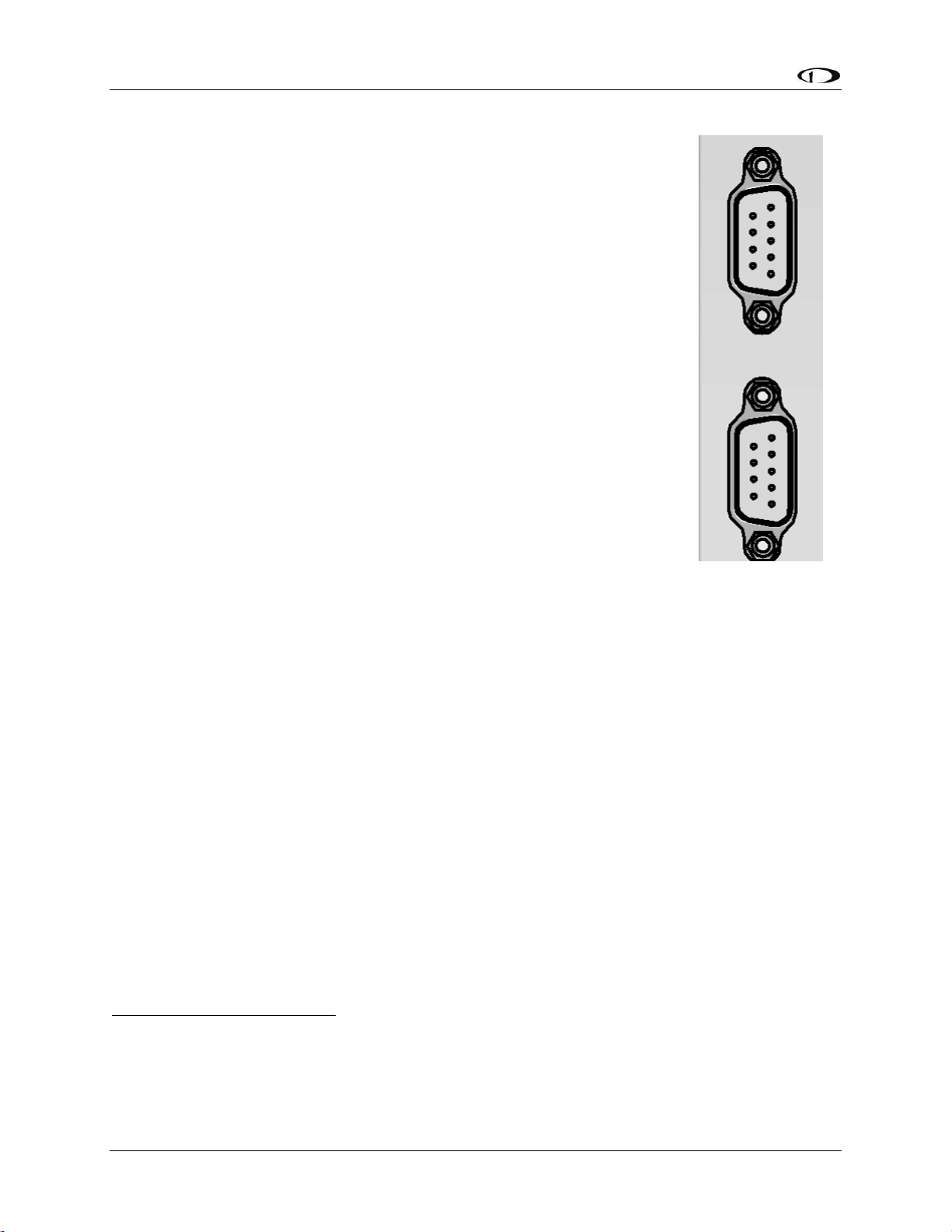
System Planning
2-2 SkyView System Installation Guide - Revision AA
9-pin D9F and D9M Connectors are SkyView Network (not RS-232
Serial)
SkyView displays and SkyView modules use D9M connectors for “SkyView
Network” connections between SkyView displays and SkyView modules1,2. This
initially causes some confusion because the same type of connector is used for
“RS-232 serial” on PCs and other (non-SkyView) devices such as GPS units. The
9-pin SkyView Network connectors on the back of a SkyView display is shown in
Figure 1 at right.
The specific use of the various pins within the 9-pin SkyView Network
connectors in a SkyView system is unique to SkyView. It is important to
understand that in SkyView, the 9-pin connectors are not electrically
compatible with RS-232 serial connections found on PCs and other devices.
One critical difference is that in a SkyView Network 9-pin D9F or D9M
connector, 3 of the 9 pins provide power, which, if connected to a RS-232
serial device, could damage it, or damage the SkyView display. For example, if
you wish to connect a GPS unit that has an RS-232 output, it will not work… and
may damage SkyView or the GPS… to connect the two units directly by plugging
in the GPS’ 9-pin connector the 9-pin connectors on the SkyView display.
RS-232 serial devices can be connected to a SkyView system; this is done via
specific pins / wires of the SV-HARNESS-D37 37-pin connector / harness on
the SkyView display. Details of connecting RS-232 serial devices are explained
in SkyView Display Installation and Configuration, RS-232 Serial Devices, and
Appendix C: Wiring and Electrical Connections, SkyView Display D37 Pinout (SV-HARNESS-D37).
SkyView Network is a “Party Line”
SkyView Network communicates between the displays and modules as a modern, multi-drop (serial
BUS) network, similar to an old-fashioned telephone party line. A more modern example of a multidrop serial network is Ethernet. SkyView Network wiring is electrically common between all SkyView
Network devices. In SkyView Network each Pin 1 of the 9-pin SkyView Network connectors and
cables are electrically connected to every SkyView Network 9-pin connector Pin 1.
The “physical” method of each connection doesn’t matter – electrical connections can be made with
splitters, hubs, multiple SkyView Network connectors on the back of a device (both connectors are
electrically common), etc. All SkyView Network devices “listen” on the SkyView Network. A SkyView
display manages (controls) all communications over SkyView Network. For example, if there are two
SV32 servos installed, the SkyView display “talks” to only one SV32 at a time. The SkyView display
distinguishes between the two SV32s by their unique (electronic) Serial Number.
1
The SV-ADSB-470 ADS-B receiver uses a D9F connector that is not compatible with SkyView Network; see the
section SV-ADSB-470 Installation and Configuration for details.
2
Dynon Avionics AP servos (wired with the SV-NET-SERVO kit) use a D9F and D9M connectors (at the servo) that is
not compatible with SkyView Network; see the section AP Servo Installation, Configuration, and Calibration for
details.
Figure 1
SkyView Display
SkyView Network
Connectors
Page 25
System Planning
SkyView System Installation Guide - Revision AA 2-3
If there is more than one SkyView display, for controlling SkyView Network communications, one
display is automatically elected as “Master”, and the other display has a “Standby” role. If the
“Master” display fails, the “Standby” display automatically becomes “Master” (failover) and begins
managing SkyView Network communications.
External Switches and Indicators
Some SkyView units provide inputs or outputs for switches and indicators that are installed external
to the SkyView unit. Some of these are required, others provide optional functionality. Appendix K:
Switches, etc. External to SkyView Units provides a comprehensive listing of all external switches or
indicators for reference in planning a SkyView system panel, stick grip, hat switches, etc.
SkyView Display Resolution
SkyView displays feature high resolution displays with non-reflective screens that are viewable in
direct sunlight.
SkyView Display
Resolution
SV-D600
800 x 480 pixels
SV-D700
SV-D900
1024 x 600 pixels
SV-D1000
SV-D1000T
SV-HDX800
1280 x 800 pixels
SV-HDX1100
Table 2 - SkyView Displays Resolution
SkyView System Maximum Number of Displays
A SkyView Classic system can include as many as three SkyView Classic and SkyView Touch
displays in any combination of SV-D700s, SV-D1000s, and SV-D1000Ts.
A SkyView SE system can include as many as three SkyView SE displays in any combination of
SV-D600s and SV-D900s.
A SkyView HDX system can include as many as three SkyView displays in any combination of SVHDX800s and SV-HDX1100s.
Page 26
System Planning
2-4 SkyView System Installation Guide - Revision AA
Power Specifications
Table 3 contains SkyView displays and devices that are powered by SkyView displays. 5A circuit
protection is recommended for SkyView displays in common configurations; 5A is the smallest
circuit breaker that is commonly available in certified versions.
SkyView Displays:
No SV-BAT-320 (see below)
No SkyView Network modules (see below)
No SV-GPS-250
No USB devices
Display brightness at maximum
Current
requirement
@ 12V DC
Current
requirement
@ 24V DC
Circuit
Protection
Recommendation
SV-D600 all S/N
2.10A
1.00A
5A
SV-D700 S/N below 4000
2.60A
1.30A
5A
SV-D700 S/N above 4000
2.10A
1.00A
5A
SV-D900 all S/N
2.00A
1.00A
5A
SV-D1000 S/N below 6000
2.70A
1.40A
5A
SV-D1000 S/N above 6000
2.00A
1.00A
5A
SV-D1000T all S/N
2.40A
1.20A
5A
SV-HDX800 all S/N
2.10A
1.00A
5A
SV-HDX1100 all S/N
2.40A
1.20A
5A
Devices powered from SkyView Displays
These devices are directly connected to an individual SkyView display and are powered by the display. Add the
current consumption of these devices to the current consumption of the SkyView display they are connected to.
This will allow you to calculate the total current that each SkyView display requires.
SV-BAT-320 (while charging)
1.00A
0.50A
N/A
SV-GPS-250
0.10A
0.10A
N/A
SV-GPS-2020
0.10A
0.05A
N/A
Video Adapter for SkyView (USB)
0.15A
0.08A
N/A
SkyView Wi-Fi Adapter (USB)
0.10A
0.05A
N/A
Devices powered via SkyView Network
These devices are connected to SkyView Network, which is powered by the SkyView display(s). If you have two
or three displays, the current requirements of these devices are shared equally between the displays. If you
have one display, add 100% of a SkyView Network device’s current to the display’s current requirement. If you
have two displays, add 50% of SkyView Network device’s current to each display’s current requirement. If you
have three displays, add 33% of SkyView Network device’s current to each display’s current requirement.
SV-ADAHRS-200/201
0.15A
0.08A
N/A
SV-AP-PANEL (not including trim motor loads)
0.05A
0.03A
N/A
SV-ARINC-429
0.10A
0.05A
N/A
SV-EMS-220 (maximum number of sensors)
0.11A
0.06A
N/A
SV-KNOB-PANEL
0.07A
0.04A
N/A
SV-MAG-236
0.15A
0.08A
N/A
Table 3 – Power Specifications for SkyView Displays, Units Powered by SkyView Displays
Example, a SV-D1000T @ 12V with:
1 – SV-BAT-320 (1.00A)
1 - SV-GPS-2020 (0.10A)
1 - SV-ADAHRS-200 (0.15A)
1 - SV-EMS-220 (0.11A)
will require 3.76A when charging the battery, 2.76A when the battery is fully charged.
Page 27
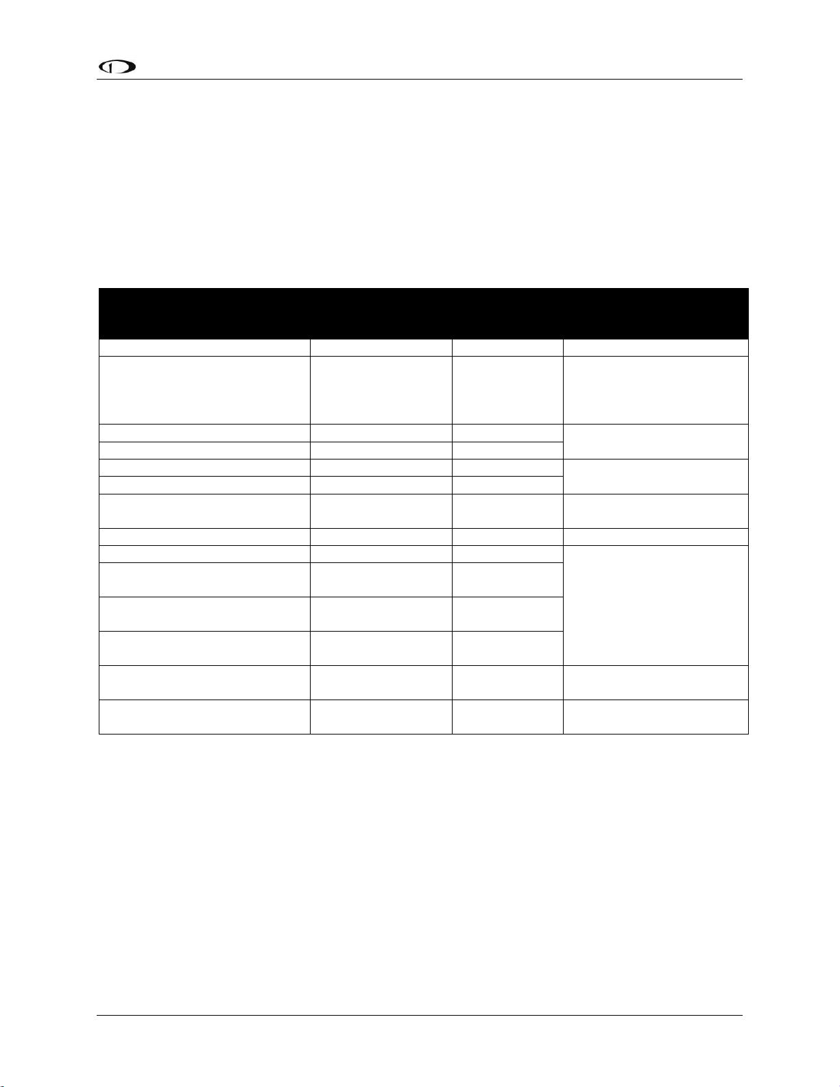
System Planning
SkyView System Installation Guide - Revision AA 2-5
Table 4 contains power specifications for SkyView units that are powered from aircraft power (not
powered by SkyView Network). The circuit protection recommendations are suitable for most
installations and assume that you are using Dynon Avionics harnesses and/or are following the
wiring advice in this Installation Guide. It may be possible to use different sized circuit protection if
the protective device has suitable load overhead for the device(s) connected to it. It is important
that circuit protection devices be appropriately sized to protect the wiring connected to them. 5A
circuit protection is recommend in most cases because that is the smallest circuit breaker that is
commonly available in certified versions, and Dynon Avionics wiring harnesses specify wire of at
least 22 AWG.
Unit
Current
requirement
@ 12V DC
Current
requirement
@ 24V DC
Circuit
Protection
Recommendation
SV-ADSB-470
0.20A
0.10A
5A
SV-AP-PANEL
(Trim motor control section)
Actual current
requirement
dependent on the trim
motor chosen
Not Applicable
12V only
5A
SV-COM-C25 - Receive
0.20A
0.10A
5A
SV-COM-C25 – Transmit
3.00A
1.50A
SV-COM-X83 – Receive
0.20A*
0.20A*
5A
SV-COM-X83 – Transmit
2.00A*
2.00A*
SV-INTERCOM-2S
0.10A*
0.10A*
5A
(Or add to another circuit)
SV-XPNDR-261/262
0.40A
0.20A
5A
Servos (All) – Not Engaged
0.13A
0.07A
5A
SV32 (all variants)
Moving @ 100% torque
1.30A
0.70A
SV42 (all variants)
Moving @ 100% torque
2.00A
1.00A
SV52 (all variants)
Moving @ 100% torque
2.80A
1.40A
Heated AOA / Pitot Probe
@ Maximum Heat
10.00A
Not Applicable
12V only
10A
Serial to Gray Code Converter
Module
0.01A*
0.01A*
5A
(or add to another circuit)
* Same current @12V and @24V – does not incorporate a switching power supply.
Table 4 – Power Specifications for SkyView Units Powered by Aircraft Power
Page 28
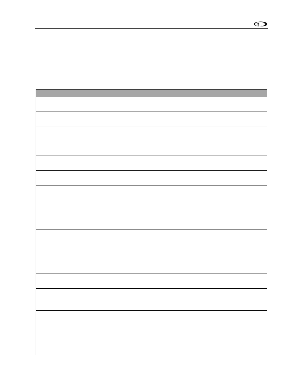
System Planning
2-6 SkyView System Installation Guide - Revision AA
Major Unit Physical Specifications
Table 5 contains physical specifications of major units. Note that dimensions listed in this table
are approximate—see the installation sections of each unit for installation drawings with
precise dimensions.
For physical specifications of minor units such as sensors, see Appendix B: Specifications, Table
99 – SkyView Minor Equipment Weights.
Unit
Dimensions
Weight
SV32
2.47” W x 4.20” H x 3.98” D
(63mm W x 107mm H x 101mm D)
2.00 lb. (0.90 kg)
SV42
2.47” W x 5.13” H x 3.98” D
(63mm W x 130mm H x 101mm D)
3.00 lb. (1.40 kg)
SV52
2.47” W x 6.05” H x 3.98” D
(63mm W x 154mm H x 101mm D)
4.00 lb. (1.80 kg)
SV-ADAHRS-200/201
4.71” W x 1.22” H x 2.61” D
(120mm W x 31mm H x 66mm D)
0.50 lb. (0.20 kg)
SV-ADSB-470
7.00” W x 1.19” H x 4.63” D
(177.8mm W x 30.1mm H x 117.6 D)
0.80 lb. (0.36 kg)
SV-AP-PANEL
3.53” x 1.80” x 1.27” D
(89.7mm x 45.7mm H x 32.4mm D)
0.30 lb. (0.15 kg)
SV-ARINC-429
4.75” W x 1.09” H x 2.61” D
(121mm W x 28mm H x 66mm D)
0.40 lb. (0.18 kg)
SV-BAT-320
3.30” W x 2.10” H x 3.90” D
(84mm W x 53mm H x 99mm D)
0.80 lb. (0.40 kg)
SV-COM-425
7.34” x 2.38” x 1.51”
(186.6mm x 60.45mm x 38.23mm)
0.75 lb. (0.34 kg)
SV-COM-PANEL
3.53” x 1.80” x 1.27” D
(89.7mm x 45.7mm H x 32.4mm D)
0.38 lb. (0.17 kg)
SV-COM-T8
(w/mounting tray)
2.5” W x 1.9”H x 6.3” D
(66mm W x 48mm H x 160mm D)
0.77 lb. (0.35 kg)
SV-D600/D700
7.64” W x 5.51” H x 2.14” D
(194mm W x 140mm H x 54mm D)
2.40 lb. (1.10 kg)
SV-D1000
(through S/N 8082)
10.32” W x 7.06” H x 2.14” D
(262mm W x 179mm H x 54mm D)
3.00 lb. (1.40 kg)
SV-D900
SV-D1000 (S/N 8083+)
SV-D1000T
10.32” W x 7.06” H x 2.33” D
(262mm W x 179mm H x 59mm D)
3.30 lb. (1.50 kg)
SV-EMS-220/221
6.35” W x 1.09” H x 2.99” D
(161mm W x 28mm H x 76mm D)
0.63 lb. (0.29 kg)
SV-GPS-250
2.19” W x 0.75” H x 3.44” D
(56mm W x 19mm H x 87mm D)
0.44 lb. (0.20 kg)
SV-GPS-2020
0.47 lb. (0.21 kg)
SV-HDX800
7.64” W 5.59” H x 3.21” D
(194mm W x 142mm H x 82mm D)
2.75 lb. (2.25 kg)
Page 29
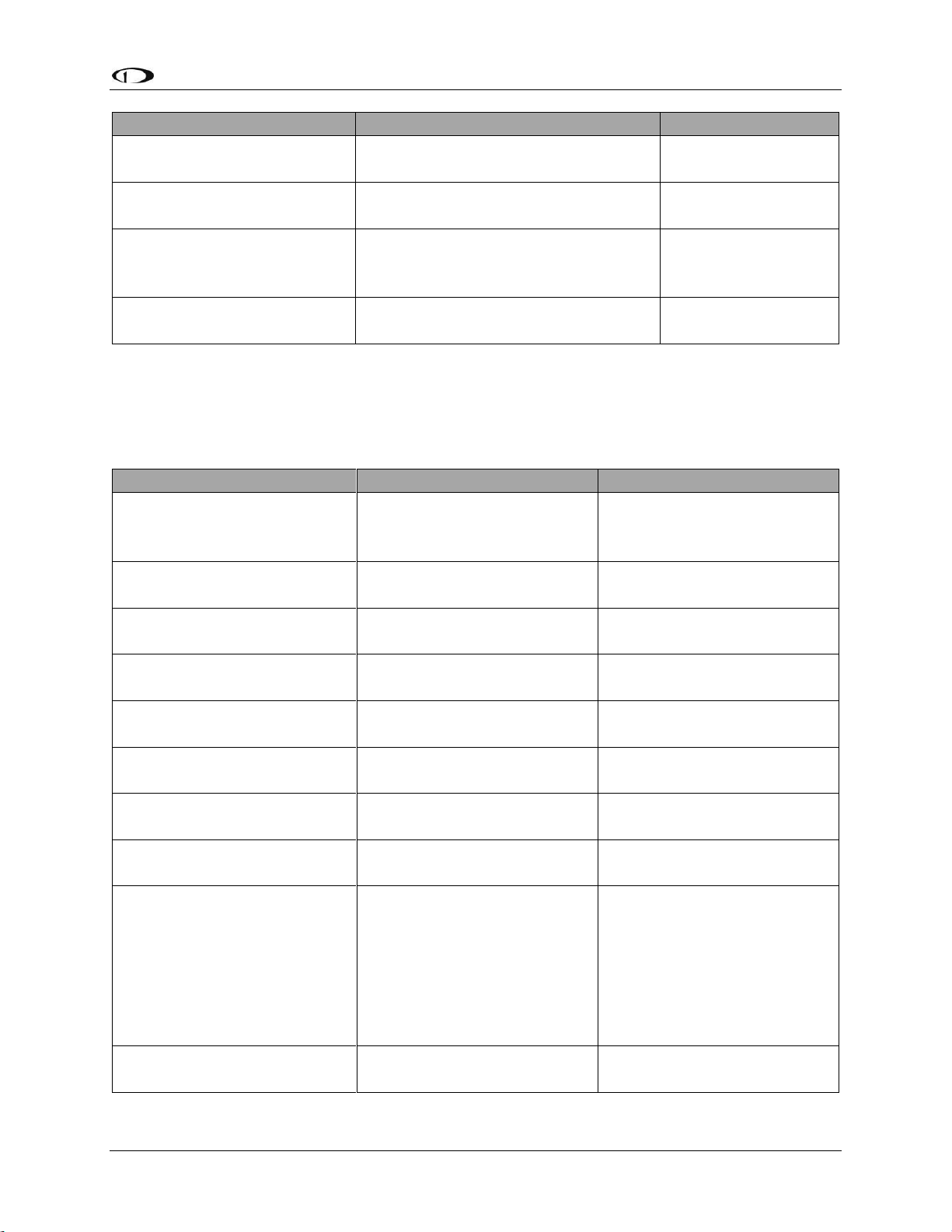
System Planning
SkyView System Installation Guide - Revision AA 2-7
Unit
Dimensions
Weight
SV-HDX1100
10.31” W x 7.1” H x 3.1” D
(262mm W x 180mm x 79mm D)
3.35 lb. (1.52 kg)
SV-KNOB-PANEL
3.53” x 1.80” x 1.27” D
(89.7mm x 45.7mm H x 32.4mm D)
0.40 lb. (0.18 kg)
SV-MAG-236
4.71” W x 1.22” H x 2.61” D
(120mm W x 31mm H x 66mm D)
(not including cable - 18” (457mm)
0.46 lb. (0.21 kg)
SV-XPNDR-261/262
(w/mounting tray)
2.5” W x 1.9”H x 6.3” D
(66mm W x 48mm H x 160mm D)
0.77 lb. (0.35 kg)
Table 5 – SkyView System Component Physical Specifications
Temperature Specifications
Table 6 contains environmental specifications for major SkyView units.
Environmental Specifications
Storage Temperature
Operating Temperature
SV32 (all variants)
SV42 (all variants)
SV52 (all variants)
-22° F to 167° F
(-30° C to 75° C)
-22° F to 140° F
(-30° C to 60° C)
SV-ADAHRS-200
SV-ADAHRS-201
-40° F to 158° F
(-40° C to 70° C)
-22° F to 140° F
(-30° C to 60° C)
SV-ADSB-470
-40° F to 158° F
(-40° C to 70° C)
-22° F to 140° F
(-30° C to +60° C)
SV-AP-PANEL
-40° F to 158° F
(-40° C to 70° C)
-22° F to 140° F
(-30° C to 60° C)
SV-ARINC-429
-40° F to 158° F
(-40° C to 70° C)
-22° F to 140° F
(-30° C to +60° C)
SV-BAT-320
-4° F to 140° F
(-20° C to 60 °C)
-4° F to 140° F
(-20° C to 60° C)
SV-COM-C25
-40° F to 158° F
(-40° C to 70° C)
-22° F to 140° F
(-30° C to 60° C)
SV-COM-X83
-67° F to 185° F
(-55° C to 85° C)
-4° F to 158° F
(-20° C to 70° C)
SV-D600
SV-D700
SV-D900
SV-D1000
SV-D1000T
SV-HDX800
SV-HDX1100
-40° F to 158° F
(-40° C to 70° C)
-22° F to 140° F
(-30° C to 60° C)
SV-EMS-220
SV-EMS-221
-40° F to 158° F
(-40° C to 70° C)
-22° F to 140° F
(-30° C to 60° C)
Page 30
System Planning
2-8 SkyView System Installation Guide - Revision AA
Environmental Specifications
Storage Temperature
Operating Temperature
SV-GPS-250
SV-GPS-2020
-40° F to 158° F
(-40° C to 70° C)
-40° F to 140° F
-40° C to 60° C
SV-KNOB-PANEL
-40° F to 158° F
(-40° C to 70° C)
-22° F to 140° F
(-30° C to 60° C)
SV-MAG-236
-40° F to 158° F
(-40° C to 70° C)
-22° F to 140° F
(-30° C to 60° C)
SV-XPNDR-261
SV-XPNDR-262
-67° F to 185° F
(-55° C to 85° C)
-4° F to 158° F
(-20° C to 70° C)
Table 6 – SkyView System Component Environmental Specifications
General System Installation Tips
Aircraft construction involves a variety of processes that create debris that can
damage Dynon Avionics components. Metalwork, in particular, will produce
metallic shavings and dust that may damage or destroy the electronics in Dynon
Avionics products if they are contaminated with this debris. Care should be taken
to ensure that Dynon Avionics products are kept away from aircraft construction
debris. Damage caused by the introduction of outside particulates into the interior
of a Dynon Avionics unit will not be repaired under warranty.
Do not physically modify SkyView displays or SkyView modules in any way that is
not specified in this manual. Damage caused to Dynon Avionics products due to
physical modifications will not be repaired under warranty.
SkyView System Can Be On During Engine Start
All Dynon Avionics units in a SkyView system incorporate robust power protection that allows
them to be powered on during engine start for full engine monitoring. SkyView displays require
a minimum of 10V, and during engine start, it’s common for the electrical system to
temporarily drop below 10V. If an SV-BAT-320 Backup Battery is not installed, SkyView may
shut off / reboot. If you wish to monitor your engine prior to engine start, an SV-BAT-320
should be installed so that the SkyView display can switch to the SV-BAT-320 when its power
inputs are not receiving at least 10V. The SkyView display will switch from SV-BAT-320 to
aircraft power when its power inputs receive voltage above 10V.
Installing SkyView in an IFR-Equipped Aircraft
SkyView SE does not integrate with any IFR navigation sources, and excludes
features and components commonly used in an aircraft equipped for IFR flight.
If you are equipping an aircraft that is capable of being flown in IFR/IMC conditions, Dynon
Avionics makes the following recommendations:
Page 31

System Planning
SkyView System Installation Guide - Revision AA 2-9
The entirety of the instrument panel and supporting avionics systems and instrumentation
should be designed so that the display of information essential for continued safe flight and
landing will remain available to the pilot after any single failure or probable combination of
failures. In other words, a usable "partial-panel" of primary flight instruments should be
preserved in the event of the failure of a SkyView display, systems that support it, or other
instruments in the aircraft.
This level of redundancy can be obtained in different ways. For example, one could utilize
multiple SkyView displays (with SV-BAT-320 backup batteries attached) including multiple
ADAHRS units connected to protect against the failure of any single display, ADAHRS, or the
electrical system. Flight instrument redundancy could also be preserved by using other separate
and independent systems such as the Dynon Avionics EFIS-D6. Some builders may elect to
combine SkyView with other more conventional “steam” gauges such as mechanical airspeed,
altitude, and attitude indicators.
To protect against aircraft electrical failures and anomalies, Dynon Avionics STRONGLY
RECOMMENDS that each SkyView display has an SV-BAT-320 Backup Battery connected to it.
SkyView’s attitude algorithm normally uses airspeed to provide superior accuracy. If a problem
develops with your airspeed reading due to mechanical blockage of pitot, disconnection of
pitot, or other pitot/static issues, a properly connected and configured GPS source acts as a
substitute. SkyView systems typically have one or more GPS sources connected to enable
Synthetic Vision and Mapping capabilities, but a primary and backup GPS connection is
especially important to preserve the attitude indication in the event of loss of airspeed
information in IFR aircraft.
In order to provide the most reliable airspeed (and therefore attitude) performance, Dynon
Avionics STRONGLY RECOMMENDS the installation of a heated pitot probe in aircraft equipped
for IFR to prevent loss of airspeed data due to icing.
Mounting Requirements
Some SkyView modules include mounting fasteners, while some do not. Mounting fasteners are
included as a convenience and installers are not required to use them. Use sensible mounting
techniques when installing equipment in suitable locations. You should reference individual
equipment sections for information regarding installation instructions.
SkyView System Construction
Appendix C: Wiring and Electrical Connections contains complete details
regarding pinouts of all SkyView system component connectors and wire harness
colors.
Overview
A SkyView system consists of displays, modules, and connection hardware. Displays manage
power for modules (not servos) and control communication between devices. Modules provide
Page 32
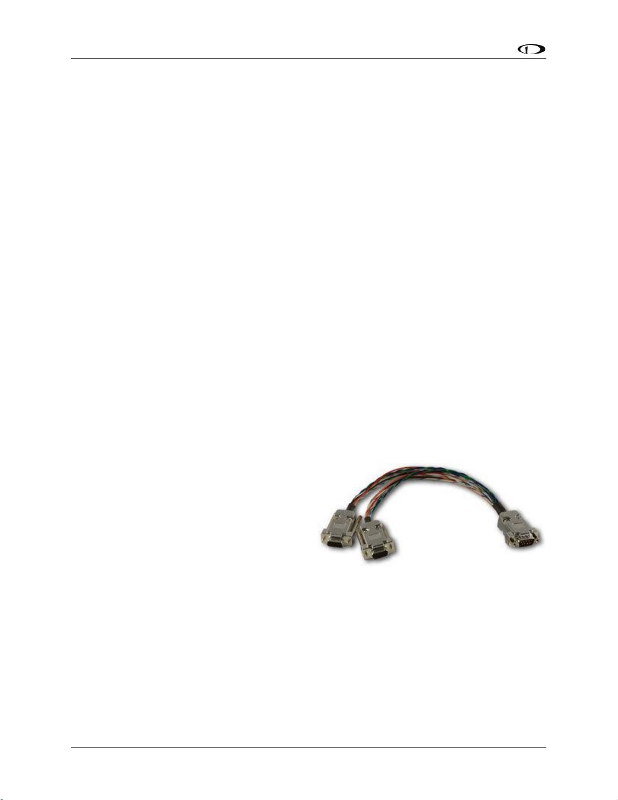
System Planning
2-10 SkyView System Installation Guide - Revision AA
data to the displays. The connection between displays and modules is referred to as SkyView
Network.
SkyView Network
SkyView displays, SkyView modules, and the SV-NET-HUB use Male DSUB 9-pin (henceforth
referred to as “D9M”) connectors. SkyView Network cables use Female DSUB 9-pin (henceforth
referred to as “D9F”) connectors. Servos have unterminated wires and we recommend the use
of one servo cabling kit (SV-NET-SERVO) per servo. All of this connection hardware is available
from Dynon Avionics.
Harnesses and Cables
Dynon Avionics SkyView harnesses and Skyview Network cables use aircraft-grade Tefzel®
wiring. The SV-HARNESS-D37 breaks out power, serial, USB and other important pins from the
back of the display. SkyView Network cables are available in a variety of lengths. The 3 and 6
foot cables have D9F connectors on both ends. The longer cables have a D9F connector on one
end and open pins on the other end. The open end allows installers to run the cable in and
through areas that would not be possible if a connector was present. The connector is installed
after the cable has been run.
The SV-NET-SERVO (one kit per servo) makes it easy to connect the SkyView system to Dynon
Avionics servos and includes 20 feet of pre-twisted wire (twisted pair 22 AWG wire for data; 20
AWG wires for power), D9 connectors, connector shells, crimp contacts, an insertion tool, heat
shrink, and zip ties. It is recommended that you read and understand Appendix C: Wiring and
Electrical Connections before working with this kit.
Splitter (SV-NET-SPL)
The SV-NET-SPL uses aircraft-grade Tefzel®
wiring, consist of a D9M input connector and
two D9F output connectors, with a length of 1
foot. The primary use for the SV-NET-SPL is the
connection of primary and backup ADAHRS in a
SkyView network from one network cable
coming from a display. For connecting multiple
SkyView modules from a SkyView Network
cable, using the SkyView Network Hub (SV-NETHUB) is recommended.
Note that SkyView systems installed prior to March 2012 are likely to have SV-NET-SPLs for all
SkyView network expansion needs. SkyView systems installed more recently are likely to have
fewer splitters (usually, just one at a dual ADAHRS installation), and one SV-NET-HUB.
In SkyView systems installed prior to March 2012, connector gender changers (SV-NET-CHG)
allowed SkyView network cables to connect to the output connector of a splitter. This allows a
cable split to occur in the middle of a long run of cable.
Figure 2 - SV-NET-SPL
Page 33

System Planning
SkyView System Installation Guide - Revision AA 2-11
SkyView Network Hub (SV-NET-HUB)
The SV-NET-HUB SkyView Network hub contains
5 SkyView Network ports. All 5 ports are
identical, thus any of the 5 ports can be used to
connect to your displays, modules, and/or
autopilot servos. Servo power should be broken
out, as is normally done. See the Autopilot Servo
Installation section of this manual for more
information about Servo wiring. The SkyView
Network Hub is designed to ease the distribution
of SkyView Network connections to multiple
SkyView Network components by allowing easy expansion of a SkyView network without
relying on a more expensive network of individual splitters. It also allows for fewer overall
connections over the splitter-only method that was primarily used prior to March 2012 as the
hub-based method requires no gender changer connectors.
Figure 4 – SV-NET-HUB Dimensions
Figure 3 - SV-NET-HUB
Page 34
System Planning
2-12 SkyView System Installation Guide - Revision AA
Test SkyView Network Cable
SkyView displays are supplied with a test SkyView network cable that is intended for bench top
testing only. The test network cable is not built with aircraft-grade Tefzel® wiring and should
not be permanently installed in an aircraft.
Ethernet Connection
SkyView systems that have more than one display should have their Ethernet ports
permanently connected together. Though not a required connection, it allows aviation and
obstacle databases to be transferred to all displays in a SkyView system when they are loaded
on any one of them. If Ethernet is not connected, aviation and obstacle databases will need to
be loaded on each display in the system individually.
Future SkyView functionality may require Ethernet to be connected as described
in this section. Therefore, Dynon Avionics strongly recommends connecting all
Ethernet ports together at this time.
The Ethernet connection between SkyView displays is in addition to the SkyView Network
connections, and should be connected on a permanent basis like other SkyView wiring. Dynon
Avionics strongly recommends “Low Smoke Zero Halogen” Ethernet cables for use in aircraft,
but any Ethernet cable – whether it is a “crossover” or normal “straight” type Ethernet cable will technically work. Low Smoke Zero Halogen Ethernet cables are available from Dynon
Avionics (SV-ETHERNET-3CC). Aircraft containing more than two SkyView displays will need an
Ethernet switch with enough ports to connect all SkyView displays together. Contact Dynon
Avionics for Ethernet switch recommendations if your aircraft has more than two displays.
There are indicator lights on the Ethernet port that are usually indicative of data
transfer on traditional Ethernet devices. In SkyView, they are used instead for
display troubleshooting purposes. See the Maintenance and Troubleshooting
section for more information about what these lights indicate.
Available Cables and Harnesses
The following table contains Dynon Avionics part numbers and descriptions for the components
that will typically be used to test and build a SkyView system. Note: network cables with the
“CP” suffix include the second connector—it just is not installed on the cable to facilitate easy
routing through tight areas of an aircraft.
Dynon Avionics P/N
Description
SV-ETHERNET-3CC
SkyView Ethernet Cable - Low Smoke Zero Halogen – 3 ft. (0.92 m)
SV-NET-TEST
SkyView Network Test Cable – 10 ft. (3.05 m)
One SV-NET-TEST is shipped with each SkyView display.
Not Aircraft-Grade Wiring – used for test only!
All harnesses and SkyView Network Cables below made with Aircraft-Grade Tefzel® Wiring
SV-HARNESS-ADSB
Wiring harness for SV-ADSB-470 – 15 ft. (4.6 m)
SV-HARNESS-D37
Primary Harness for SV-D600/SV-D700/SV-D900/SV-D1000/SV-D1000T
Page 35
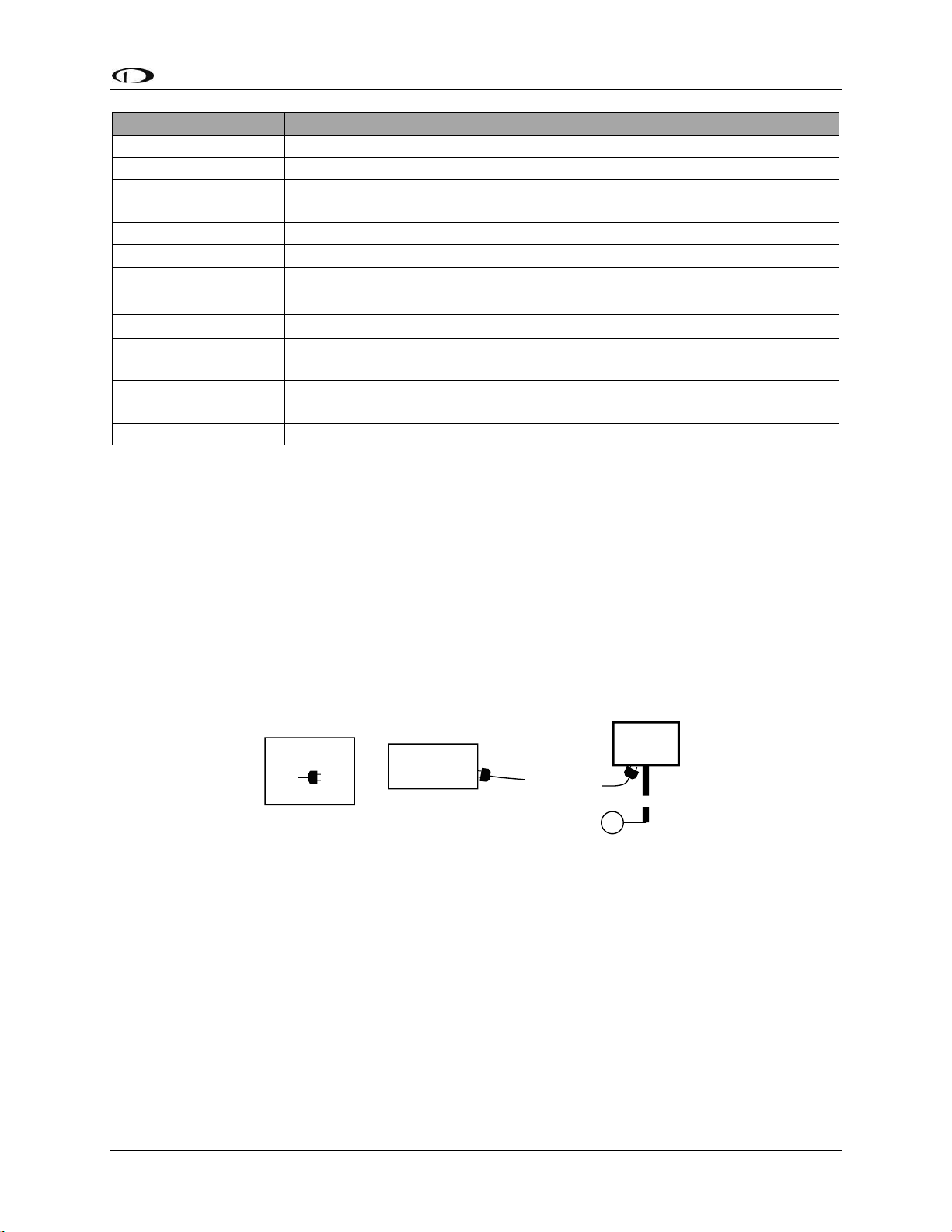
System Planning
SkyView System Installation Guide - Revision AA 2-13
Dynon Avionics P/N
Description
SV-HARNESS-XPNDR
Wiring Harness for SV-XPNDR-261/262 – 15 ft. (4.6 m)
SV-NET-1.5CC
SkyView Network Cable, both ends with connectors – 1.5 ft. (0.46 m)
SV-NET-3CC
SkyView Network Cable, both ends with connectors – 3 ft. (0.91 m)
SV-NET-6CC
SkyView Network Cable, both ends with connectors – 6 ft. (1.82 m)
SV-NET-10CP
SkyView Network Cable, 1 end connector, 1 end pins only – 10 ft. (3.05 m)
SV-NET-15CP
SkyView Network Cable, 1 end connector, 1 end pins only – 15 ft. (4.60 m)
SV-NET-20CP
SkyView Network Cable, 1 end connector, 1 end pins only – 20 ft. (6.10 m)
SV-NET-25CP
SkyView Network Cable, 1 end connector, 1 end pins only – 25 ft. (7.62 m)
SV-NET-30CP
SkyView Network Cable, 1 end connector, 1 end pins only – 30 ft. (9.10 m)
SV-NET-HUB
SkyView Network Hub (5 SkyView Network connections)
(Does not include a SkyView Network Cable – purchase separately)
SV-NET-SERVO
SkyView Network Cabling Kit for Autopilot Servos – 20 ft. (6.10 m)
One SV-NET-SERVO is used for each servo in most installations.
SV-NET-SPL
SkyView Network Splitter – 1 ft. (0.30 m)
Table 7 – Dynon Avionics SkyView Harnesses and SkyView Network Cables
Example SkyView Systems
SkyView systems are easily scalable and can accommodate a wide variety of components
ranging from a single display with one module to multiple displays with multiple modules. The
following diagrams illustrate several example SkyView systems and the components needed to
build them. Diagrams do not show a connection to aircraft power and do not imply an
installation location. Additionally, cable lengths and models pictured below should not be
blindly used as a “prescription”. Always consider your aircraft’s particular geometry and module
installation locations before purchasing harnesses, hubs, and splitters.
Figure 5 – SkyView System with One Display and One ADAHRS
SV-D1000
USB
Connector
SV-HARNESS-D37
SV-ADAHRS-200
SV-NET-10CP
(with installed D9)
KEY
DB9 Female
Page 36

System Planning
2-14 SkyView System Installation Guide - Revision AA
Figure 6 – SkyView System with One Display, One EMS, One GPS, One SV-BAT-320, and Two Redundant ADAHRS
Figure 7 – SkyView System with Two Redundant Displays, One EMS, Two Backup Batteries (One per Display),
One GPS, and Two Redundant ADAHRS
Note, that in Figure 7, the SV-GPS-250/2020’s power, ground, and output wires
are connected to both displays.
The following diagrams show two different ways to lay out a more complex system in which
there are more SkyView Network modules than available SkyView Network ports.
The first diagram reflects the way that one would typically build a network when purchasing
components prior to March 2012 before the SV-NET-HUB was available. It uses splitters to
create all additional SkyView Network connections. This connection methodology is still valid
and supported, although the use of a SV-NET-HUB is preferred going forward.
The second diagram reflects the way one can build a network utilizing the SV-NET-HUB to
expand the number of available SkyView Network ports instead of splitters. It is both less
expensive and utilizes fewer total connections (and no gender changers) when compared with
the splitter-based method. Note that a splitter is still useful for wiring two co-located redundant
SV-D1000
USB
Connector
SV-BAT-320
SV-HARNESS-D37
SV-EMS-220
SV-NET-6CC
SV-ADAHRS-200
SV-ADAHRS-201
SV-NET-SPL
SV-GPS-250
GPS
Wire
Bundle
SV-NET-10CP
(with installed D9)
KEY
DB9 Male
DB9 Female
Page 37

System Planning
SkyView System Installation Guide - Revision AA 2-15
ADAHRS modules. In most installations, this is the only application of the SV-NET-SPL that is
necessary when utilizing the SV-NET-HUB to build a SkyView Network.
Figure 8 – SkyView System with Two Redundant Displays, One EMS, Two Backup Batteries (One per Display),
Two Redundant GPS, Two Redundant ADAHRS, Two Servos, and one Transponder using splitters (legacy
installation method)
Page 38

System Planning
2-16 SkyView System Installation Guide - Revision AA
Note, that in Figure 8, each SV-GPS-250/2020’s power, ground, and output wires
are connected to both displays on different serial ports. The primary SV-GPS250/2020 should be connected to serial port 5 on each display. The secondary SVGPS-250/2020 should be connected on another serial port on each display.
Additionally, if there are both multiple displays and multiple SV-GPS-250/2020
units in the system, power for the secondary GPS should be sourced from the GPS
power wire on the second display – in other words, each SV-GPS-250/2020 should
receive power from a different display. Reference the SV-GPS-250/2020 GPS
Receiver Installation and Configuration Section for more information on this
configuration.
Figure 9 – SkyView System with Two Redundant Displays, One EMS, Two Backup Batteries (One per Display),
Two Redundant GPS, Two Redundant ADAHRS, Two Servos, and one Transponder using a hub (recommended
installation method)
Page 39
System Planning
SkyView System Installation Guide - Revision AA 2-17
Note, that in Figure 9, each SV-GPS-250/2020’s power, ground, and output wires
are connected to both displays on different serial ports. The primary SV-GPS250/2020 should be connected to serial port 5 on each display. The secondary SVGPS-250/2020 should be connected on another serial port on each display.
Additionally, if there are both multiple displays and multiple SV-GPS-250/2020
units in the system, power for the secondary GPS should be sourced from the GPS
power wire on the second display – in other words, each SV-GPS-250/2020 should
receive power from a different display. Reference the SV-GPS-250/2020 GPS
Receiver Installation and Configuration Section for more information on this
configuration.
HSI Requirements
SkyView’s HSI overlay on the PFD DG can be driven by its own built-in Navigation Mapping
system. Additionally, external GPS and NAV radio sources can be used as well. Reference the
RS-232 Serial Devices and SV-ARINC-429 Installation and Configuration sections of this guide
for more information regarding external data sources.
The SV-GPS-250/2020 provides only a position source (a subset of the data
provided by other GPS devices such as a Garmin X96). The SV-GPS-250/2020 cannot
provide navigation without the Navigation Mapping system and appropriate
aviation databases installed.
Table 8 outlines the functionality enabled by each source of data.
Data
SkyView
SV-GPS-250
SV-GPS-
2020
SkyView
Map
System
Generic
NMEA
GPS
Generic
Aviation
GPS
ARINC-429
GPS via SV-
ARINC-4293
ARINC-429 /
Serial (SL30)
NAV4
SkyView
SV-ADAHRS-200
SV-ADAHRS-201
SkyView
SV-MAG-
236
4-5 Hz GPS
Updates
Bearing Pointers
Course Deviation
Course Direction
Distance to
Waypoint
Glideslope
GPS Altitude
5
Ground Speed
Ground Track
Latitude
Longitude
LPV/VNAV GPS
Approaches
6
3
SkyView SE does not support SV-ARINC-429.
4
SkyView SE does not support external navigation devices.
5
Requires additional Aviation format serial input into SV-ARINC-429 module.
6
Approach-certified WAAS GPS units only.
Page 40
System Planning
2-18 SkyView System Installation Guide - Revision AA
Data
SkyView
SV-GPS-250
SV-GPS-
2020
SkyView
Map
System
Generic
NMEA
GPS
Generic
Aviation
GPS
ARINC-429
GPS via SV-
ARINC-4293
ARINC-429 /
Serial (SL30)
NAV4
SkyView
SV-ADAHRS-200
SV-ADAHRS-201
SkyView
SV-MAG-
236
Magnetic Heading
SkyView Time
Source
To/From Flag
Tuned Frequency
True Airspeed
7
VFR Vertical
Guidance
8
Virtual-DME
Waypoint or
Station Identifier
Winds9
Table 8 – HSI Requirements
7
True Airspeed calculation requires a connected OAT sensor.
8
Some models (including Garmin X96 series).
9
Winds calculation specifically requires GPS, a connected OAT sensor, IAS, and magnetic heading.
Page 41
SkyView System Installation Guide - Revision AA 3-1
3. Basic SkyView Display Operation
After reading this section, you should be familiar with basic SkyView display operation including
how to use joysticks, knobs, and buttons, how to turn displays on and off, how to access and
navigate menus, how to configure the SkyView network, and how to perform Software updates
and other file operations.
The SkyView SV-D700 and SV-D1000/D1000T displays are identical in functionality
and presentation. Other than the Touch features of the SV-D1000T (not present on
the SV-D700 or the SV-D1000), the only difference is in the size and resolution of
the screen.
The SkyView SE SV-D600 and SV-D900 displays are identical in functionality and
presentation. The only difference is in the size and resolution of the screen.
The SkyView SV-HDX800 and SV-HDX1100 displays are identical in functionality and
presentation. The only difference is in the size of the screen.
Screen Synchronization
SkyView is designed to operate as an integrated system. SkyView configurations with more than
one display automatically share and synchronize settings on all displays. In-flight settings such
as baro and bugs are synchronized in real time as they are adjusted. Setup menu items are
synchronized when the user exits the setup menu and also at boot up. Aviation and obstacle
databases are synchronized when they are loaded on any screen if Ethernet is connected.
It is not possible to have displays on the same network that do not share configurations,
settings, and real time items. Even if a unit is off when settings are adjusted, they will be
synchronized when they boot up.
For displays to properly synchronize settings their tail numbers must be the same
and SkyView Network must be configured correctly. See the Network Setup and
Status Section of this manual for information about these required setup steps.
Only one setup menu in the network may be open at once. If you try to open a setup menu on a
display while it is open on another display, you will see OTHER SCREEN IN SETUP on the screen
and thus cannot open the setup menu. There is no "master" in the system; changes made on
any screen in the system will be automatically reflected on all other screens.
Some things are purposefully not synchronized on displays: Software, sensor configuration files
(.sfg), and local display settings. You must ensure that each display is running the appropriate
Software, up-to-date databases, and sensor configuration file. All of these files are available for
download at http://downloads.dynonavionics.com. Also ensure that each display’s local
settings are appropriately configured.
Page 42

Basic SkyView Display Operation
3-2 SkyView System Installation Guide - Revision AA
Display Bezel Layout
The following diagram illustrates the front of an SV-D1000 display and its important parts.
Figure 10 – SkyView Display Front Bezel Layout
Note the top bar, screen, joystick and button labels, light sensor, two joysticks and eight
buttons.
The top bar displays important textual information. The top bar shows time, autopilot status,
and transponder status (SV-XPNDR-261/262 or Garmin GTX-327 only). Reference the LOCAL
DISPLAY SETUP Menu Section of this guide for details on how to configure the top bar.
The screen shows PFD, Engine, and Moving Map data, configuration information, and system
alerts. Its layout is user-configurable. Reference the SkyView Pilot’s User Guide for instructions
on how to configure the layout of your screen.
Joystick and button labels are also on the screen. Joystick and button functionality is contextual
based on what is onscreen and these labels show the user the current function. For example, the
(RNG) label above joystick 2 in Figure 10 shows that turning that joystick will either increase or
decrease the range shown on the Moving Map.
The set of button labels displayed immediately after the display turns on is referred
to as the Main Menu.
Page 43
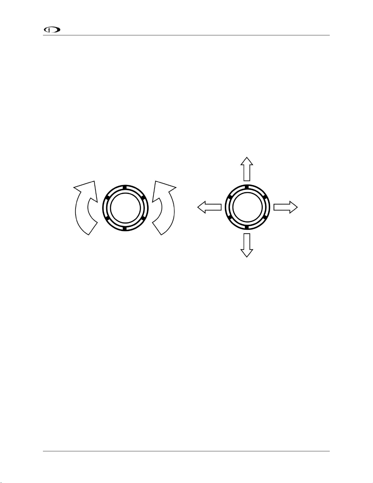
Basic SkyView Display Operation
SkyView System Installation Guide - Revision AA 3-3
Each SkyView display has an integrated light sensor in the bezel. This light sensor can be used
for automatic backlight level management. Reference the Display Setup Section of this guide for
instructions on how to configure the display for automatic backlight level management.
Joystick and Button Operation
Joysticks and buttons are used for various functions including powering the unit on and off,
entering and navigating menus, and adjusting values.
Operation Basics
SkyView Classic and SkyView SE joysticks can be turned and moved. Specific joystick behavior is
addressed in subsequent sections of this guide when necessary.
Figure 11 – SkyView Classic and SkyView SE Joystick Turn (left) and Movement (right) Directions
(Pushbutton Function Not Shown)
Page 44

Basic SkyView Display Operation
3-4 SkyView System Installation Guide - Revision AA
Because it incorporates an advanced touch screen interface, SkyView HDX knobs (unlike
SkyView Classic and SkyView SE) do not move (click) up, down, left, or right – they only rotate
clockwise and counter-clockwise. Like SkyView Classic and SkyView SE’s knobs, SkyView HDX
knobs incorporate a pushbutton function.
Figure 12 – SkyView HDX Knob Rotation and Pushbutton Action
A keypad button has a function if there is a label above it. If there is no label, there is no
function. The figure below shows an example button label.
Figure 13 – Example Button Label
When you press a button, its label is highlighted. When you let go, that button’s action is
invoked.
Button labels are called out in all capital letters such as BACK, EXIT, FINISH, and
CLEAR. This guide directs users to press a button by using its label. For example,
when this guide asks you to press FINISH, it is asking you to press the button with
the FINISH label above it.
SkyView Classic and SkyView SE Joystick and Button Operation Example
When a parameter needs to be adjusted, the SkyView Classic and SkyView SE’s joystick controls
are used to change the parameter. When setting values with the joystick, each character
(symbol, letter or digit) must be selected and adjusted successively.
Page 45

Basic SkyView Display Operation
SkyView System Installation Guide - Revision AA 3-5
Figure 14 – Adjusting Successive Characters in SkyView Classic and SkyView SE
In this example, the first time you turn the joystick, you toggle between the “-“ and “+”
symbols. To change the succeeding characters, you must move the cursor joystick to the right.
In this example, you first adjust the “-” or “+” character, move the joystick right, then adjust the
one hundreds digit, and so forth. Once you have adjusted the value appropriately, press
ACCEPT or move the joystick to the right again.
At times, the next item in the menu path in this guide may be a joystick selection OR a button
push—the correct choice will be apparent.
SkyView Touch – Touch Interface Features Not Used in Setup Menus
Touch interface features are not enabled in the SV-D1000T’s Setup Menu; touch interface
features are not generally used during installation and initial setup.
In normal operation, in addition to using the conventional buttons and joystick knobs, many of
the on-screen elements can be touched to control SkyView. Details about how touch is used in
normal operation are covered in the SkyView Classic Pilot’s User Guide.
SkyView HDX Knob and Button Operation Example
When a parameter needs to be adjusted, the SkyView HDX’s knob / button is used to change
the parameter. When setting values with the knob, each character (symbol, letter or digit) must
be selected and adjusted successively.
Figure 15 – Adjusting Successive Characters in SkyView HDX
When the parameter is first displayed, the most significant (left-most) field is highlighted.
Rotate the knob clockwise to increment the parameter, or counter-clockwise to decrement the
parameter. In this example, the first time you rotate the knob, you toggle between the “-“ and
“+” symbols.
After changing the parameter to the desired value, push the knob (pushbutton) to accept the
desired value. The cursor will automatically change to the next field (to the right). Once you
have adjusted the value appropriately (finished entering the desired data), pushing the knob
will generally accept the entire value and return to the menu. Occasionally, it is necessary to
press ACCEPT button (on the keypad).
Page 46

Basic SkyView Display Operation
3-6 SkyView System Installation Guide - Revision AA
When in a list of menu items, to move up and down the menu, simply rotate the knob clockwise
to move down the menu, and counter-clockwise to move up the menu. When the desired menu
is highlighted, push the knob (pushbutton) to enter the desired menu.
Menu Navigation
After the display turns on, you will see a screen similar to the one in Figure 10. This guide refers
to the label bar at the bottom of the screen as the Main Menu.
Throughout this guide, the “>” character is used to indicate a sequence of menu selections or
other actions you would take as you navigate the menu system. Menu selections which are
followed by “…” indicate full-screen wizard interfaces which guide you through the appropriate
steps. These wizard interfaces are not described in detail in this guide, as the on-screen
instructions provide adequate information.
SkyView menus follow this structure: SETUP MENU > MENU > ... > MENU > PAGE or WIZARD.
The setup menus (In Flight Setup or Setup) are the root of most menu navigation. Each nested
menu is more specific than the previous one and there is no set limit for the number of nested
menus before reaching a page. A page or wizard is at the end of the chain and it is where the
user can perform a specific action such as change a specific setting, configure a SkyView
network, or set up the layout of the onscreen engine gauges. Wizards employ easy-to-follow
onscreen instructions.
For example, SETUP MENU > SYSTEM SETUP > MEASUREMENT UNITS > BAROMETER indicates
entering the SETUP MENU, then selecting SYSTEM SETUP, then selecting MEASUREMENT
UNITS, and then entering the BAROMETER Menu to select INHG, MBAR, or MMHG.
Table 9 is a summary of menu navigation.
Desired Menu Action
User Action
Enter the Setup Menu
Simultaneously press and hold buttons 7 and 8
(if airspeed is greater than zero, you will enter the
In Flight Setup Menu)
Scroll through different menus
Rotate joystick or knob
OR
SkyView Classic / SE: Move either joystick up or down
Enter menu
SkyView Classic /SE: Move joystick toward the right
SkyView HDX: Push the knob (pushbutton)
Return to previous menu
SkyView Classic / SE: Move joystick toward the left
(saves settings)
OR
Press BACK (saves settings)
OR
Press CANCEL (does not save settings)
Save adjusted value
Press ACCEPT
Reset adjustable value
Press DEFAULT
Page 47

Basic SkyView Display Operation
SkyView System Installation Guide - Revision AA 3-7
Desired Menu Action
User Action
Save settings and return to Main
Menu
Press EXIT
Table 9 – Menu Navigation Summary
Basic Display Operation Procedures
This subsection covers basic operation procedures for displays. Detailed instructions for various
menus and individual menu items are described later in this guide.
How to Turn the System On or Off
Table 10 summarizes the procedures for toggling SkyView system power states.
SkyView System Displays
Toggle SkyView System Power
One display
Toggle primary power state
OR
Toggle display power by pressing and holding button 1
Multiple displays
Toggle primary power state
OR
Toggle all displays off or on by pressing and holding
button 1 on each display.
Table 10 – How to Toggle SkyView System Power State
Loss of Aircraft Power with SV-BAT-320 Connected
If external power is lost to a display that is connected to a SV-BAT-320 Backup Battery, it will
either stay on for an additional 30 seconds or stay on indefinitely depending on whether or not
the aircraft is in flight. This feature minimizes SV-BAT-320 discharge when on the ground and
master/external power is shut off normally while simultaneously reducing pilot workload during
an actual in-flight power loss.
If the aircraft is not in flight, SkyView displays the message “POWERING DOWN IN xx SECONDS”
while counting down from 30 seconds. During this countdown, the menu displays the buttons
STAY ON and PWR OFF at the bottom of the screen. Press PWR OFF to turn off the SkyView
display immediately. Press STAY ON to keep the SkyView display on via the connected SV-BAT-
320. If STAY ON is pressed, the display will continue to use the SV-BAT-320 to power itself until
the battery’s charge is depleted or the display is turned off manually pressing and holding
button 1. Finally, if neither button is pressed before the countdown expires, the display will
automatically turn off after 30 seconds to conserve the SV-BAT-320 charge.
If the aircraft is in flight, SkyView displays the message “AIRCRAFT POWER LOST” with no
additional count down. This ensures that active pilot action is required to turn off a display
when power is lost in-flight and SV-BAT-320 power is available. The STAY ON and PWR OFF
buttons are still offered, but the display will stay on indefinitely unless PWR OFF is pressed.
Page 48
Basic SkyView Display Operation
3-8 SkyView System Installation Guide - Revision AA
How to Reboot the Display
Press and hold buttons 1, 2 and 5 simultaneously to instantly reboot the system. This may be
helpful if you need to cycle power after changing certain settings and for general
troubleshooting.
How to Manually Adjust the Screen Brightness (Dim)
Manual control of screen brightness (SCREEN > DIM button) is not supported in
SkyView SE. Screen brightness in SkyView SE can changed with automatic brightness
control using the ambient light sensor, or using an external dim control signal.
A SkyView display’s backlighting (brightness) is primarily controlled by its ambient light sensor.
If you have more than one SkyView display, each display’s ambient light sensor is incorporated.
You can adjust the brightness / dimming to your preference by SCREEN > DIM to access the DIM
Menu. To decrease or increase the backlight brightness press DEC- or INC+, respectively or
simply rotate the knob labeled DIM – clockwise to brighten, counter-clockwise to dim. To set
the backlight brightness to 100%, press FULL. SkyView will not allow you to dim the display(s) to
a level that would cause it to be illegible for the ambient lighting conditions.
Reference the Display Setup Section of this guide for instructions on specifying the display’s
backlight brightness control method.
How to Enter the Joystick / Knob Function Menu
The Joystick / Knob Function menus are used to specify which bug that knob or joystick adjusts
if rotated. For example, knob or joystick 1 could be set to adjust the Heading bug and knob or
joystick 2 could be set to adjust the Altitude bug.
If you have a SkyView Classic or SkyView SE display, move the joystick up, down, left, or right to
enter its Function Menu.
If you have a SkyView HDX display, push the knob (pushbutton) to enter its Function Menu.
Figure 16 illustrates the Joystick / Knob menu.
Figure 16 – Joystick / Knob Menu
To set the function of a SkyView Classic or SkyView SE joystick:
1. Move a joystick up, down, left, or right to enter the Joystick’s function Menu.
2. Choose the joystick function by moving the joystick up or down.
3. Confirm the highlighted function by moving the joystick left or right.
Page 49

Basic SkyView Display Operation
SkyView System Installation Guide - Revision AA 3-9
To set the function of a SkyView HDX knob:
1. Push the knob (pushbutton) to enter the knob’s Function Menu.
2. Choose the joystick function by rotating the knob clockwise or counter-clockwise.
3. Confirm the highlighted function by pushing the knob (pushbutton)
OR
Wait approximately 7 seconds; the Function Menu will close and the highlighted
function will be selected.
If the Map Page is onscreen, the joystick or knob closest to the Moving Map is labeled (RNG) and
is used to adjust the map’s range. It cannot be assigned a different function.
If the Joystick / Knob Function menu does not display all of the Bugs that you wish
to select from, some of the Bugs are disabled. To enable the desired Bugs, go to the
PFD menu and select BUGS. In the BUGS menu, enable the desired bugs. Then the
desired Bugs will be selectable in Joystick / Knob menu.
How to Enter the Setup Menus
There are two setup menus: the Setup Menu and the In Flight Setup Menu. Simultaneously
pressing and holding buttons 7 and 8 will open one of these menus. If airspeed is zero, the
Setup Menu opens. If airspeed is greater than zero, the In Flight Setup Menu opens.
You may also access the Setup Menu from the In Flight Setup Menu by using the ENTER FULL
SCREEN SETUP MENU… option.
How to Adjust Time Zone Offset
First, configure the Top Bar to display time in SETUP MENU > LOCAL DISPLAY SETUP > TOP BAR
SETUP > TIME: ZULU | LOCAL.
Then, adjust your preferred offset from the time currently displayed on the Top Bar – SETUP
MENU > SYSTEM SETUP > TIME.
How to Configure Units of Measure
Displayed units can be configured for altitude, distance and speed, temperature, barometer,
pressure, and volume. Displayed units are configured on the Measurement Units Page (SETUP
MENU > SYSTEM SETUP > MEASUREMENT UNITS).
In Flight Setup Menu
This menu contains links that may be useful during flight:
ADAHRS SOURCE SELECTION…
FLIGHT ANGLE PITCH ADJUST…
COMPASS CALIBRATION….
AOA CALIBRATION…
AUTOPILOT SETUP…
ENTER FULL SCREEN SETUP MENU…
Page 50
Basic SkyView Display Operation
3-10 SkyView System Installation Guide - Revision AA
Note that this menu occupies only half of the screen and that all of the links in the In Flight
Setup Menu are accessible via the SETUP MENU.
SETUP MENU
This menu contains links to system configuration options:
SYSTEM EVENT
SYSTEM SOFTWARE
SYSTEM SETUP
LOCAL DISPLAY SETUP
PFD SETUP
EMS SETUP
MAP SETUP (Not supported in SkyView SE)
AUTOPILOT SETUP
TRANSPONDER SETUP
TRAFFIC SETUP (Not supported in SkyView SE)
VP-X SETUP (Not supported in SkyView SE or SkyView HDX [as of Software v15.0])
ACM SETUP (Not supported in SkyView SE)
ADS-B STATUS (Not supported in SkyView SE)
COM RADIO SETUP
HARDWARE CALIBRATION
Note that this menu occupies the entire screen. The menus above have menus of their own. The
information in this section contains information on the purposes of each of the above menus as
well as a list of each menu's respective menus and their functions.
Pages and wizards that require users to do something have explicit onscreen
instructions. Most actions are simple enough and onscreen instructions are more
than adequate. In these cases, explicit instructions are not contained in this guide.
In cases where onscreen instructions are not present, instructions are included in
this guide.
The menu options descriptions in this section are intended to be introductory /
overview, not comprehensive. Comprehensive explanations of menu options can be
found onscreen, in the SkyView system, in the installation instructions in the
specific section of this manual for each subsystem, such as SV-EMS-220/221 or SVXPNDR-261/262.
SYSTEM EVENT Menu
The SYSTEM EVENT menu will only appear if the SkyView display detects that a “system event”
has occurred on (one of your) SkyView display(s).
Page 51

Basic SkyView Display Operation
SkyView System Installation Guide - Revision AA 3-11
If no critical system events have occurred on your SkyView display, “SYSTEM EVENT” will not
appear as a menu item.
If SYSTEM EVENT does appear, it contains instructions on what to do next.
SYSTEM SOFTWARE Menu
You must have a USB flash drive that is recognizable by the display in one of the
USB slots to open this menu. All of the functions under this menu either write to or
read from the flash drive.
Detailed instructions for all of the menus listed below are included in the Software
Updates and File Operations Section of this guide.
The SYSTEM SOFTWARE Menu contains links to the following wizards:
UPGRADE SYSTEM SOFTWARE... – Use this wizard to update Software on your SkyView
system.
LOAD FILES... – Use this wizard to load files such as settings or configuration files or delete
files from the USB flash drive.
EXPORT SETTINGS... – Use this wizard to export the settings on your SkyView system to a
USB flash drive. Note that (as of V6.0) calibration settings are not exported, including servo
calibrations, fuel tank calibrations, and compass calibrations.
EXPORT USER DATA LOGS… – Use this wizard to export user data logs in human-readable
CSV format. See Appendix F: User Data Logs for further information about user data logs.
EXPORT USER WAYPOINTS… – Use this wizard to export all of the User Waypoints that are
currently stored in your SkyView system.
Page 52

Basic SkyView Display Operation
3-12 SkyView System Installation Guide - Revision AA
EXPORT DYNON DIAGNOSTIC FILE... – This specialized data log can only be interpreted by
Dynon Avionics personnel; there is no data in it that can be interpreted by SkyView pilots.
Dynon Avionics Technical Support may request this log in the course of troubleshooting,
especially for issues related to AP performance. Note that this log is very big – over 500 MB
– and takes minutes to save to a USB flash drive. Unless directed to export this log by Dynon
Avionics, there is no reason to do so.
If you have more than one SkyView display in your system, you may be requested to save
the Dynon Avionics Diagnostic File from each of your SkyView displays as each display can
sometimes contain different diagnostic data. If you save the Dynon Avionics Diagnostic File
from multiple displays onto the same USB flash drive, use the 33-character name field to
distinguish the two files, such as naming one “LEFT” and the other one “RIGHT”.
SYSTEM SETUP Menu
This menu contains menus and pages related to the entire SkyView system. When a setting is
changed in one of these menus, it is synchronized to other SkyView displays.
SKYVIEW NETWORK SETUP – Enter this menu to configure your SkyView network or to
check on network status (i.e., display important SkyView module information).
WI-FI SETUP – Enter this menu to configure the Wi-Fi system – password, etc.
SERIAL PORT SETUP – Enter this menu to configure the five general purpose serial ports on
all displays.
AUDIO SETUP – Enter this menu to configure the options and volume for SkyView’s audio
output capability.
AIRCRAFT INFORMATION – Enter this page to record important information regarding your
aircraft. Specifically, enter the tail number of your aircraft–it is used to create unique
SkyView configuration files. It is also used for other purposes. Note that for US planes, the
leading N is a required part of the TAIL NUMBER. TAIL NUMBER should not include dashes
(-) or spaces. Examples:
Correct: N12AB
Incorrect: N-42SV or N 42SV
MEASUREMENT UNITS – Enter this page to configure displayed units (e.g., feet or meters).
TIME – First, configure the Top Bar to display time in SETUP MENU > LOCAL DISPLAY SETUP
> TOP BAR SETUP > TIME: ZULU | LOCAL. Then, in this menu, adjust your preferred offset
from the time currently displayed on the Top Bar.
ARINC-429 – Enter this page to set up ARINC-429 devices connected to SV-ARINC-429
modules.
SCREEN LAYOUT SETUP – Enter this page to configure the availability of the PDF Page,
Engine Page, and Map Page on this display and throughout the system (when more than
one display is installed).
PRIMARY COM – Selects the COM radio to be displayed on the Top Bar and receive a
frequency setting when the APT→COM button is pushed in the MAP MENU. If only one
COM radio is installed, this must be set. If two COM radios are installed, only one can be
displayed on the Top Bar and receive a frequency setting when the APT→COM button is
pushed in the MAP MENU.
Page 53

Basic SkyView Display Operation
SkyView System Installation Guide - Revision AA 3-13
DISPLAY COM IN TOP BAR – Selects whether, or not, frequencies, PTT status, etc. from the
COM radio (selected in PRIMARY COM, above) is displayed.
DATA LOG SETUP – Enter this page to configure the recording frequency of SkyView’s
internal data logging feature, or to clear recorded data. See the User Data Logs Appendix for
further information about user data logs.
LOCAL DISPLAY SETUP Menu
This menu contains menus and pages related to the individual SkyView display on which this
menu is displayed. These settings can be different on one display from another display.
INSTALLED DATABASES – Shows the various databases that are installed on this display and
their respective versions.
DISPLAY HARDWARE INFORMATION – Shows important hardware status information such
as the “Edition” of your SkyView display (SKYVIEW, or SKYVIEW SE), serial number of your
display and the voltage of the attached SV-BAT-320. Reference the Returning SkyView
Components to Service after Repair Section of this guide for more information about the
Display Hardware Information Page.
BRIGHTNESS SETUP – Choose between manual, automatic, or external screen backlight
control. Manual screen backlight control is managed by the user in the DIM Menu with the
DEC-, INC+, and FULL buttons. Automatic screen backlight control is managed by a default
dimming profile in the display. A compatible external control signal is required for external
backlight control. Reference the Brightness Setup Section for more information.
TOP BAR SETUP – Configure the top bar on the SkyView display's screen.
GPS FIX STATUS – Shows fix quality information for the GPS source that is being used as the
active position source for SkyView’s moving map and synthetic vision. Note that this does
not show information about other GPS sources that may be available for HSI and backup
position use.
BATTERY BACKUP (SV-BAT-320) STATUS – Shows the status of automated tests of the SV-
BAT-320.
LICENSE – This page shows the status of Software products that can be purchased and
licensed to add features to SkyView. This page is also the place where license codes can be
redeemed to activate features on your SkyView System.
DISPLAY LANGUAGE – ENGLISH (ENGLISH) | (alternate language). If a language pack is
installed, you can configure this display to display the alternate language. If a language pack
has not been loaded, this option will be grayed out and not accessible. Language packs can
be downloaded from http://downloads.dynonavionics.com.
Alternate languages are not supported in SkyView SE – SkyView SE will display only
in US English. If you intend to install and use SkyView SE, do not install an alternate
language pack.
VIDEO INPUT SETUP – If a SkyView Video Input Adapter (USB) is connected to this display,
options such as video input format and orientation can be selected. If a SkyView Video Input
Adapter (USB) is not installed, this selection is grayed out and not accessible.
Page 54

Basic SkyView Display Operation
3-14 SkyView System Installation Guide - Revision AA
PFD SETUP Menu
This menu contains menus and pages related to Primary Flight Display page and data source
(ADAHRS module).
ADAHRS SOURCE SELECTION–This page has a list of all configured SkyView ADAHRS modules
and their respective status. The ADAHRS module used as the PFD’s source of data can be
selected.
FLIGHT ANGLE PITCH ADJUST – This page allows you to adjust the displayed pitch of the
waterline symbol (aircraft reference on the attitude indicator) to compensate for the
aircraft’s attitude in level flight. That attitude can change depending on aircraft loading. This
setting is not intended to compensate for an ADAHRS module that is not installed correctly.
AIRSPEED LIMITATIONS – Enter this menu to configure the V-speeds and specify optimal
flight parameters such as best angle of climb speed, best rate of climb speed, and
maneuvering speed.
VERTICAL SPEED SCALE – Enter this page to configure the vertical speed tape's scale.
G METER – Enter this page to configure G values that will cause the G Meter to be
automatically displayed when exceeded; to set the yellow/red cautionary color ranges of
the G meter; and whether or not the max/min recorded Gs are reset at each SkyView bootup.
FLIGHT PATH MARKER – Enter this page to enable/disable display of the flight path marker.
EXTREME PITCH WARNING – Enter this page to enable/disable display of the extreme pitch
warning indicators.
ANGLE OF ATTACK – Enter this page to enable/disable display of the Angle of Attack
indicator.
ALTITUDE BUG ALERTER – Enter this page to configure the altitude alerter, an audible alert
when you are approaching or departing the altitude set in the ALT bug.
o CAPTURE BAND: When the altitude of the aircraft flies within this amount of
feet/meters of the altitude bug (when displayed), SkyView will announce
“approaching altitude” aurally (if audio output is configured)
o DEVIATION BAND: When the altitude of the aircraft climbs above or descends below
the altitude bug by the amount of feet or meters set here, SkyView will announce
“departing altitude” aurally (if audio output is configured).
PFD MODE
o LAYOUT
ALWAYS EFIS – The EFIS layout will always be displayed. The EFIS / SIX-PACK
button is not present in the PFD > MODE menu.
ALWAYS SIX-PACK – The SIX-PACK layout is always displayed. The EFIS / SIX-
PACK button is not present in the PFD > MODE menu.
SELECTABLE – the EFIS / SIX-PACK button is present in the PFD > MODE
menu, allowing either EFIS or SIX-PACK layout on PFD.
o WIDE ANGLE VIEW
Page 55
Basic SkyView Display Operation
SkyView System Installation Guide - Revision AA 3-15
ALWAYS NORMAL – The NORMAL view of the horizon on the PFD will always
be displayed. The WIDE ON / OFF button is not present in the PFD > MODE
menu.
ALWAYS WIDE – The WIDE view of the horizon on the PFD will always be
displayed. The WIDE ON / OFF button is not present in the PFD > MODE
menu.
SELECTABLE – The WIDE ON / OFF button is present in the PFD > MODE
menu, allowing either WIDE or NORMAL views of the horizon on the PFD.
BARO MISMATCH WARNING – Enables / disables a warning message when the current
SkyView BARO setting and nearest valid ADS-B METARS report barometric pressure are
significantly different.
EMS SETUP Menu
This menu is not accessible if a SV-EMS-220/221 is not installed. Reference the
Autopilot Servo Calibration and Test Procedures Section of this guide for more
information.
This menu contains menus and pages related to Engine Monitoring System page and data
source (EMS module).
ENGINE INFORMATION – Set important information regarding the engine in your aircraft
such as engine type and horsepower. The user-entered information here is used to calculate
quantities such as % power and special operating limitations.
SENSOR INPUT MAPPING... – This wizard configures the individual multipurpose pins of the
SV-EMS-220/221(s) to specific engine and environmental sensors. Reference the EMS
Sensor Input Mapping Section of this guide for instructions on how to navigate and use this
menu to map sensors.
SCREEN LAYOUT EDITOR – This wizard configures the placement and style of the onscreen
EMS gauges on EMS pages. Reference the EMS Screen Layout Editor Section of this guide for
instructions on how to use this wizard.
SENSOR SETUP – Configures the ranges, alarm conditions, and graphical display properties
of sensors. Reference the EMS Sensor Setting Section of this guide for more information
regarding sensor setup.
DUAL EMS SETUP – If a second SV-EMS-220/221 is installed, configures how the pins
(inputs) of the second SV-EMS-220/221 are used.
(Note: Support for dual SV-EMS-220/221 modules is supported only in SkyView Classic; this
feature is not available in SkyView SE or SkyView HDX (as of Software v15.0).
SENSOR DEBUG DATA – Displays diagnostic / troubleshooting data for engine sensors. Also
displays the version of the EMS Sensor Definitions file loaded on this SkyView display. See
Appendix H: Sensor Debug Data for how to interpret the information displayed on this page.
MAP SETUP Menu
This menu contains menus and pages related to MAP page and data sources.
Page 56

Basic SkyView Display Operation
3-16 SkyView System Installation Guide - Revision AA
TERRAIN WARNING COLORS – Sets whether Red and Yellow terrain warning are provided on
the Map Page
RED AND YELLOW START – When the above setting is set to “YES”, these settings how far
above or below the aircraft’s current altitude the red and yellow colors persist.
AUTOPILOT SETUP Menu
This menu is not accessible until the autopilot servos in the system have been
successfully calibrated and tested. Reference the Autopilot Servo Calibration and
Test Procedures Section of this guide for more information.
This menu configures various aspects of the Dynon Avionics Autopilot system.
STATUS – Displays diagnostic / troubleshooting information for the AP system.
AUTOPILOT CONTROLS – Chooses the EXPERT or SIMPLIFIED mode. Note that the EXPERT
mode must be selected for the Dynon Avionics SV-AP-PANEL to be active.
ROLL AXIS – Roll axis setup and tuning parameters.
PITCH AXIS – Pitch axis setup and tuning parameters.
DISENGAGE BUTTON – Configure disengage button options such as hold to engage, enable
broken line detect, and control wheel steering mode.
FLIGHT DIRECTOR – Chooses the SINGLE CUE (INVERTED V) or DUAL CUE (CROSS BARS)
mode of flight director to be displayed on the PFD.
TRANSPONDER SETUP Menu
This menu is not accessible unless a SV-XPNDR-261/262 is setup and configured.
Reference the SV-XPNDR-261/262 Installation and Configuration Section of this
guide for more information.
This menu contains options that are used to set up and configure the SV-XPNDR-261/262
module.
HARDWARE CALIBRATION Menu
This menu contains links to the following menus:
ADAHRS CALIBRATION – Enter this menu to make altitude adjustments (e.g., baro and
altitude offset) and access the compass and AOA calibration wizards.
EMS CALIBRATION – Enter this menu for EMS sensor calibration. You will have options to
calibrate fuel tanks and position potentiometers that have been mapped in the Sensor Input
Mapping Wizard. Calibration wizards contain onscreen instructions.
AP SERVO CALIBRATION – Enter this menu for autopilot servo calibration. Reference the AP
Servo Installation, Configuration, and Calibration Section of this guide for more details.
TRIM MOTOR CONFIGURATION – Enter this menu to configure one or two trim motors
(connected to / powered by the Dynon Avionics SV-AP-PANEL 15-pin connector) for
automatic trim control (Autopilot Auto-trim) during AP operation. Reference the Autopilot
Auto-trim Section of the SV-AP-PANEL Installation section of this guide for more details.
Page 57

Basic SkyView Display Operation
SkyView System Installation Guide - Revision AA 3-17
Note that if an ADAHRS, EMS, or Servos are not present on the SkyView network,
this menu will note the absence by displaying “(EMS NOT DETECTED)”, “(ADAHRS
NOT DETECTED)”, or “(SERVOS NOT INSTALLED)”
Software Updates and File Operations
Dynon Avionics continually provides new functionality and capabilities to your SkyView system
via Software updates. Use the resources mentioned in the Contact Information Section of this
document to stay current on Software availability for SkyView.
Software updates and file operations are performed using a USB flash drive.
USB Flash Drive Considerations
A 4 GB or 8 GB USB flash drive is shipped with each SkyView display. There is
nothing unique about this USB flash drive, including the data included on it.
Dynon Avionics recommends that you have a variety of USB flash drives available
for various purposes, to dedicate to a specific task. For example, maintain a
separate USB flash drive for EXPORT SETTINGS files; another for updating Software,
and another for updating Aviation / Obstacle databases, etc. While a high
resolution terrain database may require as much as 4 GB, a SkyView Software
update may require only 50 MB. To display Seattle Avionics charts, a 16 GB USB
flash drive is required. For most purposes, such as saving datalogs and typical
updates, A 1 GB or 2 GB USB flash drive will be adequate.
Dynon Avionics recommends the use of “name brand” USB flash drives – “house
brand” USB flash drives can sometimes fail prematurely, causing corrupted files or
lost data.
If it is ever necessary to reformat a USB flash drive, the format that is compatible
with SkyView is “FAT32”
In order to open the SYSTEM SOFTWARE Menu, you must have a USB flash drive plugged in to
your SkyView display.
Updating the Software on a SkyView display automatically updates all of the
modules connected on the same SkyView network, except for other SkyView
displays. Each display must be updated individually.
Prior to updating Software, all SkyView Network devices must be powered on and
online. If all previously configured SkyView Network devices are not detected, a
warning screen will appear. The most common cause for this error that power is off
to the autopilot servos (AP switch not ON). As soon as the offline module(s) resume
communicating with SkyView, the Software update will automatically proceed.
(SkyView Network devices do not include SV-ADSB-470 and SV-XPNDR-261/262 –
those devices are connected via serial ports).
Page 58
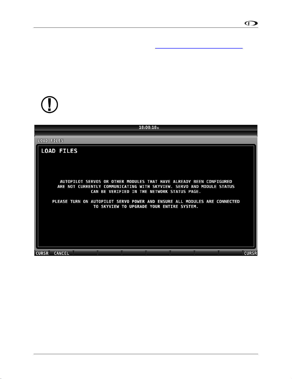
Basic SkyView Display Operation
3-18 SkyView System Installation Guide - Revision AA
How to Update Software
1. Download the latest SkyView Software file from http://downloads.dynonavionics.com.
2. Copy the Software file onto your USB flash drive. The Software file must be in the root
directory of the drive in order to be recognizable by the SkyView display.
3. Insert the USB flash drive into one of the SkyView display’s USB ports.
4. SETUP MENU > SYSTEM SOFTWARE > UPGRADE SYSTEM SOFTWARE…) > (one more right
click).
If some SkyView Network modules (or other displays) are not powered on or
connected to the SkyView network, you will see a screen that is similar to Figure 17
below.
Figure 17 – Some SkyView Network devices not online, cannot update
If you see a screen similar to the one in Figure 17 above, power on or reconnect all SkyView
Network devices. This error is typically caused by Autopilot servos or SV-COM-C25 radio not
being powered on.
5. Update the Software on the unit by pressing UPDATE or press CANCEL to return to the
SYSTEM SOFTWARE Menu.
6. To aid in troubleshooting, during the Software update process, your SkyView system’s
previous configuration files are automatically written to the USB flash drive in a
subdirectory (folder) called “settings_archive”:
TAILNUMBER_SNXXXX_SOFTWAREVERSION_SENSORS_SW_UPGRADE.sfg
Page 59

Basic SkyView Display Operation
SkyView System Installation Guide - Revision AA 3-19
TAILNUMBER_SNXXXX_SOFTWAREVERSION_SW_UPGRADE.sfg
How to Export System Settings
This operation creates a set of files on the USB flash drive that contain display
settings, equipment settings, and important calibration information. All of the
filenames contain the tail number and the Software version.
1. Insert the USB flash drive into one of the display’s USB sockets.
2. Go to the Export Settings Wizard (SETUP MENU > SYSTEM SOFTWARE > EXPORT
SETTINGS…).
3. Create a file name for the settings file.
4. Save the settings file onto the flash drive by pressing EXPORT or press CANCEL to return to
the SYSTEM SOFTWARE menu.
How to Load and Delete Files
1. Download file from http://downloads.dynonavionics.com such as terrain or EMS files or use
another source for the SkyView file.
2. Copy the file onto your USB flash drive. The file must be in the root directory of the drive in
order to be recognizable by the display.
3. Insert the USB flash drive into one of the display’s USB sockets.
4. Go to the Load Files Wizard (SETUP MENU > SYSTEM SOFTWARE > LOAD FILES…).
5. Select a file and press:
a. LOAD to load the file onto the system.
b. CANCEL to return to the SYSTEM SOFTWARE menu.
c. REMOVE to delete the file from the USB flash drive.
How to Export Data Logs and Waypoints
EXPORT DATA LOGS
Data logging, and how to export datalogs is discussed in depth in Appendix F: User Data Logs.
EXPORT USER WAYPOINTS
This option exports all of the User Waypoints that are currently stored in your SkyView system.
EXPORT DYNON DIAGNOSTIC FILE
This specialized data log can only be interpreted by Dynon Avionics Engineers; there is no data
in it that can be interpreted by SkyView pilots. Dynon Avionics Technical Support may request
this log in the course of troubleshooting, especially for issues related to AP performance. Note
that this log is very big – over 500 MB – and takes minutes to save to a USB flash drive. Unless
directed to export this log by Dynon Avionics, there is no reason to do so. This file is too large to
send in an email message.
If you have more than one SkyView display in your system, you may be requested to save the
Dynon Avionics Diagnostic File from each of your SkyView displays as each display can
sometimes contain different diagnostic data. If you save the Dynon Avionics Diagnostic File
Page 60

Basic SkyView Display Operation
3-20 SkyView System Installation Guide - Revision AA
from multiple displays onto the same USB flash drive, use the 33-character name field to
distinguish the two files, such as naming one “LEFT” and the other one “RIGHT”.
If Dynon Avionics Technical Support has requested that you send a Dynon Diagnostic File, go to
http://www.dynonavionics.com/docs/upload.html to transmit the file to Dynon Avionics.
Please reference any previous communications with Dynon Avionics Technical Support such as
Case number, RMA number, etc.
Page 61

SkyView System Installation Guide - Revision AA 4-1
4. SkyView Display Installation and Configuration
This section contains information and diagrams that specifically apply to installation of SkyView
Classic, SkyView SE, and SkyView HDX displays. After reading this section, you should be able to
determine how to prepare a panel for display installation, how to mount a display, how to
make all necessary electrical connections, and also how to configure a display.
Figure 18 is a high-level overview of a suggested installation and configuration procedure for
SkyView displays and their associated components.
Figure 18 – Suggested SkyView Display Installation Procedure
Choose a panel
location based on
Location
Requirements
Section
Mount display in
panel
Install SkyView
Display Harness
(SV-HARNESS-D37)
Connect power
and ground wires
with fuse or
breaker on power
Connect other
SkyView modules
(e.g., ADAHRS and
EMS)
Connect external
serial devices
(e.g., transponder
and GPS)
Check for
firmware
update
No
new
firmware
New
firmware
Download and
install firmware
Download and
install terrain
database
Configure display
settings and
SkyView Network
Prepare the
panel (cut
opening and drill
holes)
Reference
other chapters
in this guide...
Test display
power (turn on or
use multimeter)
Update terrain
database?
(outside North
America)
Yes
No
Download and
install aviation
database
Update
aviation
database?
Yes
No
Page 62
SkyView Display Installation and Configuration
4-2 SkyView System Installation Guide - Revision AA
Physical Installation
Display
Panel Cutout
Bezel Outline
SV-D600
6.97” x 5.35”
(177.038mm x 135.890mm)
7.636” x 5.512”
(193.954mm x 140.005mm)
SV-D700
SV-D900
9.68” x 6.90”
(245.872mm x 175.260mm)
10.320” x 7.064”
(262.128mm x 179.426mm)
SV-D1000
SV-D1000T
SV-HDX800
6.97” x 5.35”
(177.04mm x 135.89mm)
7.64” x 5.59”
(194.0 mm x 142.0mm)
SV-HDX1100
9.68” x 6.28”
(245.87mm x 159.50mm)
20.31” x 7.07”
(262mm x 179.5mm)
Table 11 – SkyView Displays Installation Dimensions Quick Overview
If you are converting your panel from a Dynon Avionics EFIS-D100, EMS-D120, or
FlightDEK-D180, note that the SV-D600, SV-D700, and SV-HDX800 displays have a
slightly larger panel cutout than those products and the existing panel cutout for
those products must be slightly enlarged.
Location Requirements for SkyView Displays
Observe the following guidelines when choosing a location for a SkyView display:
SkyView displays require about 2.4” (61mm) of free space behind the panel, depending on
mounting surface thickness.
Consider the ease, or difficulty of disconnecting multiple connectors when removing a SkyView
display from the panel. Plan for either:
o Providing sufficient slack in the cables so that the SkyView display can be removed
from the panel and then the cables disconnected, or…
o Disconnecting (and reconnecting) the cables from behind the panel prior to
removing the SkyView display from the panel.
The SkyView Display Harness (SV-HARNESS-D37) extends about 3” (76mm) from the back of the
display.
Add a 1.0” (25.4 mm), minimum, beyond the physically required volume for the SkyView
display’s heat sinks and fans to operate.
Avoid placing the display near heater vents or any source of extremely hot air.
While SkyView displays do not (normally) require a forced cooling air, if the aircraft
is to be operated in hot climates, the builder should ensure that the stated
operating temperature range for SkyView displays is not exceeded.
The display should be easily viewable without any obstructions.
SkyView Displays have no internal inertial sensors and do not need to be mounted in the same
orientation as the ADAHRS or other modules.
Page 63
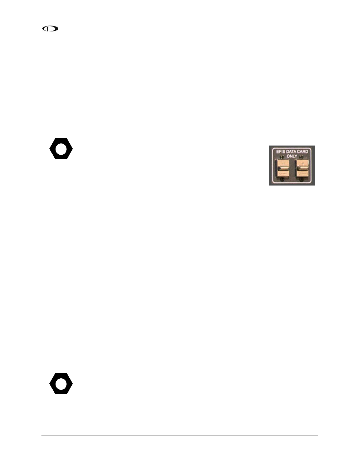
SkyView Display Installation and Configuration
SkyView System Installation Guide - Revision AA 4-3
Displays only support a landscape viewing orientation; do not mount in portrait orientation.
There are a total of three USB connectors (ports) on a SkyView display. One USB
port is included on a cable as part of the Dynon Avionics SV-HARNESS-D37. The
other two USB ports are on the rear of the SkyView display (see Figure 21 – SVD600 and SV-D700 Dimensions and Figure 23 – SV-D900, SV-D1000 and SV-D1000T
Dimensions).
The two USB ports on the rear of the SkyView display are used for:
SkyView Wi-Fi Adapter, P/N 201211-000
SkyView Video Input Adapter, P/N 102211-000
(Third party) Panel mount USB extension cable
If you will not be installing both of these options, you may want
to install a “panel mount USB extension cable” as shown in
Figure 21 at right (excerpted from the Advanced Flight Systems
[AFS] Quick Panel System). A USB connector installed on the
panel provides convenient access to a USB port for your
SkyView display, used updating Software, updating databases,
and displaying electronic charts (for which the USB flash drive is
semi-permanently connected).
Thus if panel space allows, we recommend that you install at least one panel mount
USB connector for each SkyView display. Suitable panel mount USB cables can be
found by searching on the Internet for “panel mount USB”.
Figure 21 and Figure 23 on the following pages show the mechanical dimensions of the SkyView
displays. Use the dimensions (in inches) found in the appropriate diagram to plan for the space
required by the display.
To mount a SkyView display, cut an appropriately sized rectangular opening in your panel, drill
out the mounting holes, and use the included mounting screws to fasten the display to the
panel.
SkyView Classic and SkyView SE displays are shipped with #6-32 hex-drive round head
fasteners. Fasteners are 5/8” in length and require a 5/64” hex drive tool. Dynon Avionics
recommends fastening the included mounting screws to nut plates installed behind the panel. If
access behind the panel allows, standard #6-32 lock nuts or nuts with lock washers can be used.
Do not rivet SkyView displays to the panel as this will hinder future removal if necessary.
SkyView Classic and SkyView SE Display / Panel Unit Screws
SkyView Classic and SkyView SE displays and SkyView panel units can be purchased
from Dynon Avionics – P/N 102487-000. Note that these screws are not intended
for use with SkyView HDX displays.
Figure 19
Panel Mount USB
Page 64
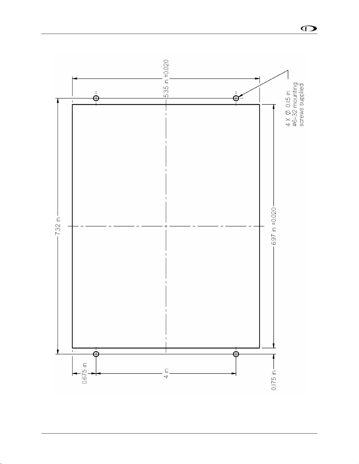
SkyView Display Installation and Configuration
4-4 SkyView System Installation Guide - Revision AA
Figure 20 – SV-D600 and SV-D700 Panel Cutout and Mounting Hole Dimensions - NOT ACTUAL SIZE
Page 65

SkyView Display Installation and Configuration
SkyView System Installation Guide - Revision AA 4-5
Figure 21 – SV-D600 and SV-D700 Dimensions
Page 66
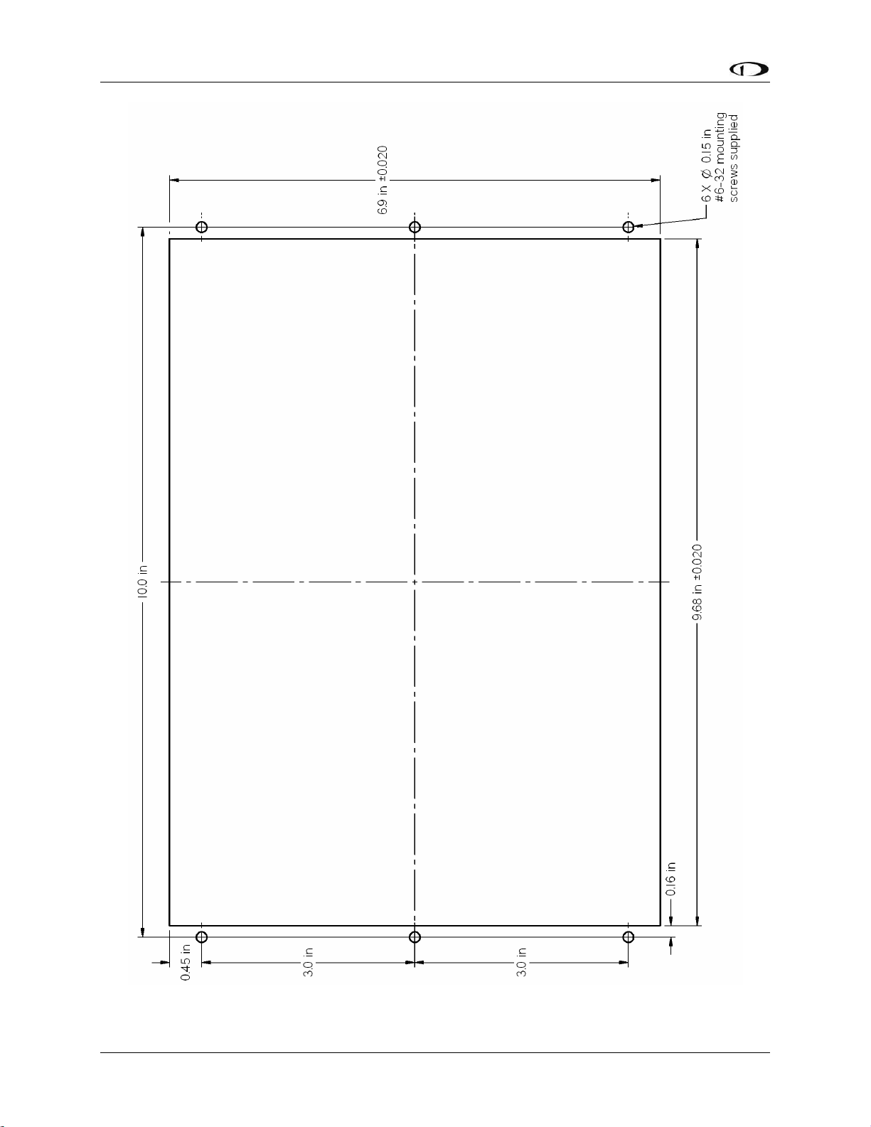
SkyView Display Installation and Configuration
4-6 SkyView System Installation Guide - Revision AA
Figure 22 – SV-D900, SV-D1000 and SV-D1000T Panel Cutout and Mounting Hole Dimensions – NOT ACTUAL SIZE
Page 67
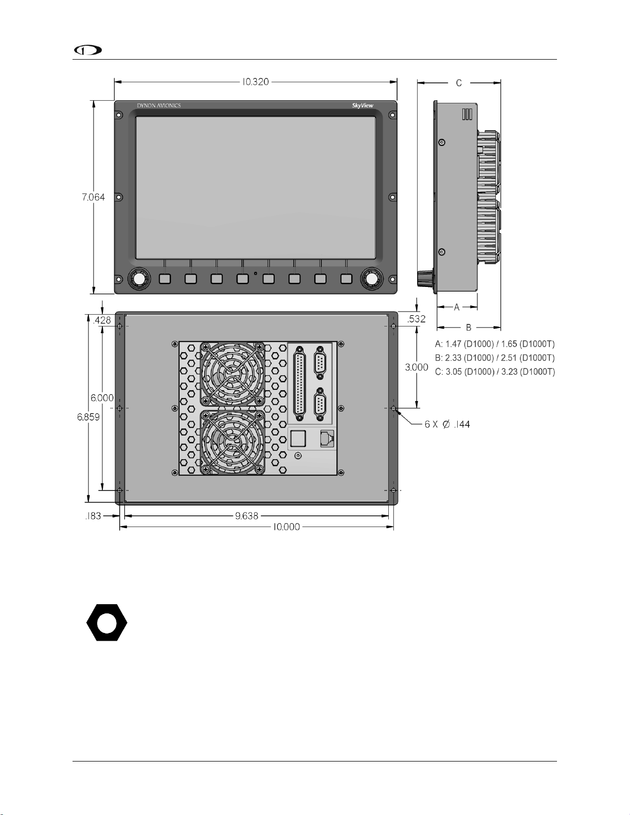
SkyView Display Installation and Configuration
SkyView System Installation Guide - Revision AA 4-7
Figure 23 – SV-D900, SV-D1000 and SV-D1000T Dimensions
(Dimension A: above) is 1.47 inches as stated above.
dimension of the enclosure (Dimension A: above) is 1.65 inches (same enclosure as
the SV-D1000T).
Page 68

SkyView Display Installation and Configuration
4-8 SkyView System Installation Guide - Revision AA
Figure 24 – Panel Cutout and Mounting Hole Dimensions – NOT ACTUAL SIZE
Page 69

SkyView Display Installation and Configuration
SkyView System Installation Guide - Revision AA 4-9
Figure 25 – SV-HDX800 Front Dimensions
Page 70
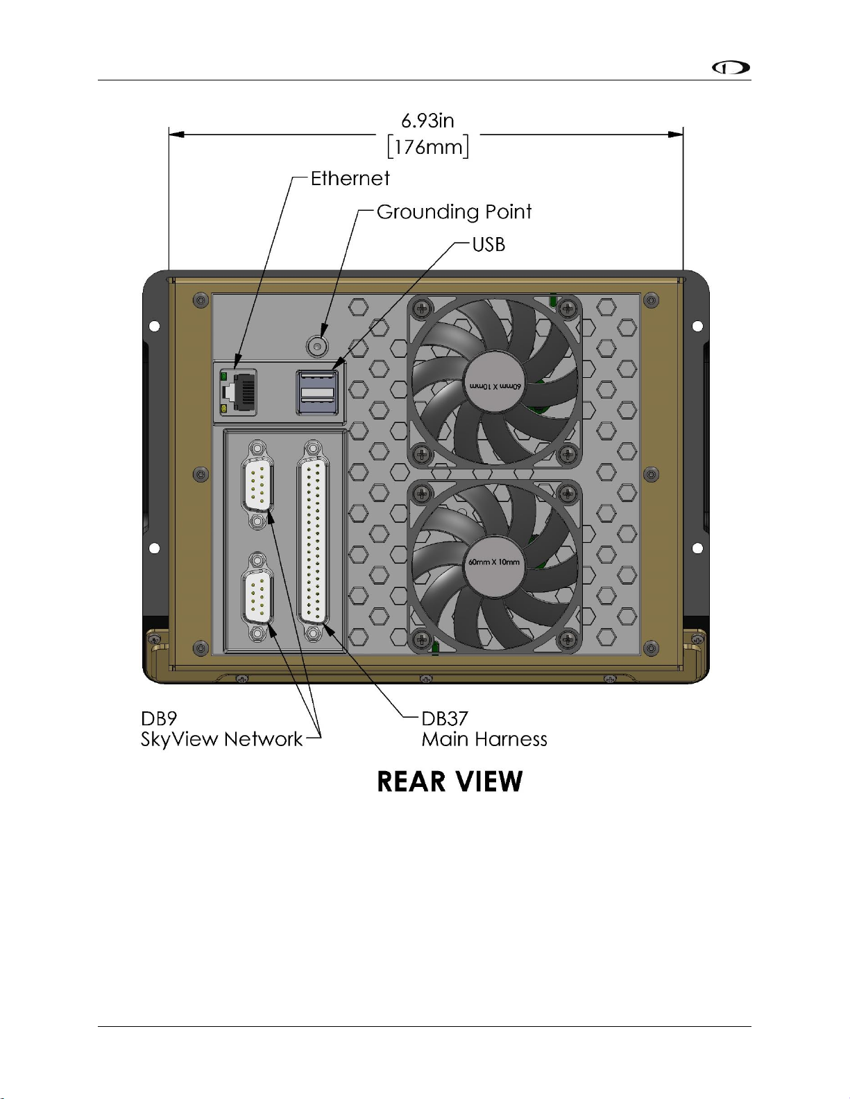
SkyView Display Installation and Configuration
4-10 SkyView System Installation Guide - Revision AA
Figure 26 – SV-HDX800 Rear Dimensions
Page 71

SkyView Display Installation and Configuration
SkyView System Installation Guide - Revision AA 4-11
Figure 27 – SV-HDX800 Side Dimensions
Page 72

SkyView Display Installation and Configuration
4-12 SkyView System Installation Guide - Revision AA
Figure 28 – SV-HDX1100 Panel Cutout and Mounting Hole Dimensions - NOT ACTUAL SIZE
Page 73

SkyView Display Installation and Configuration
SkyView System Installation Guide - Revision AA 4-13
Figure 29 – SV-HDX1100 Front Dimensions
Page 74
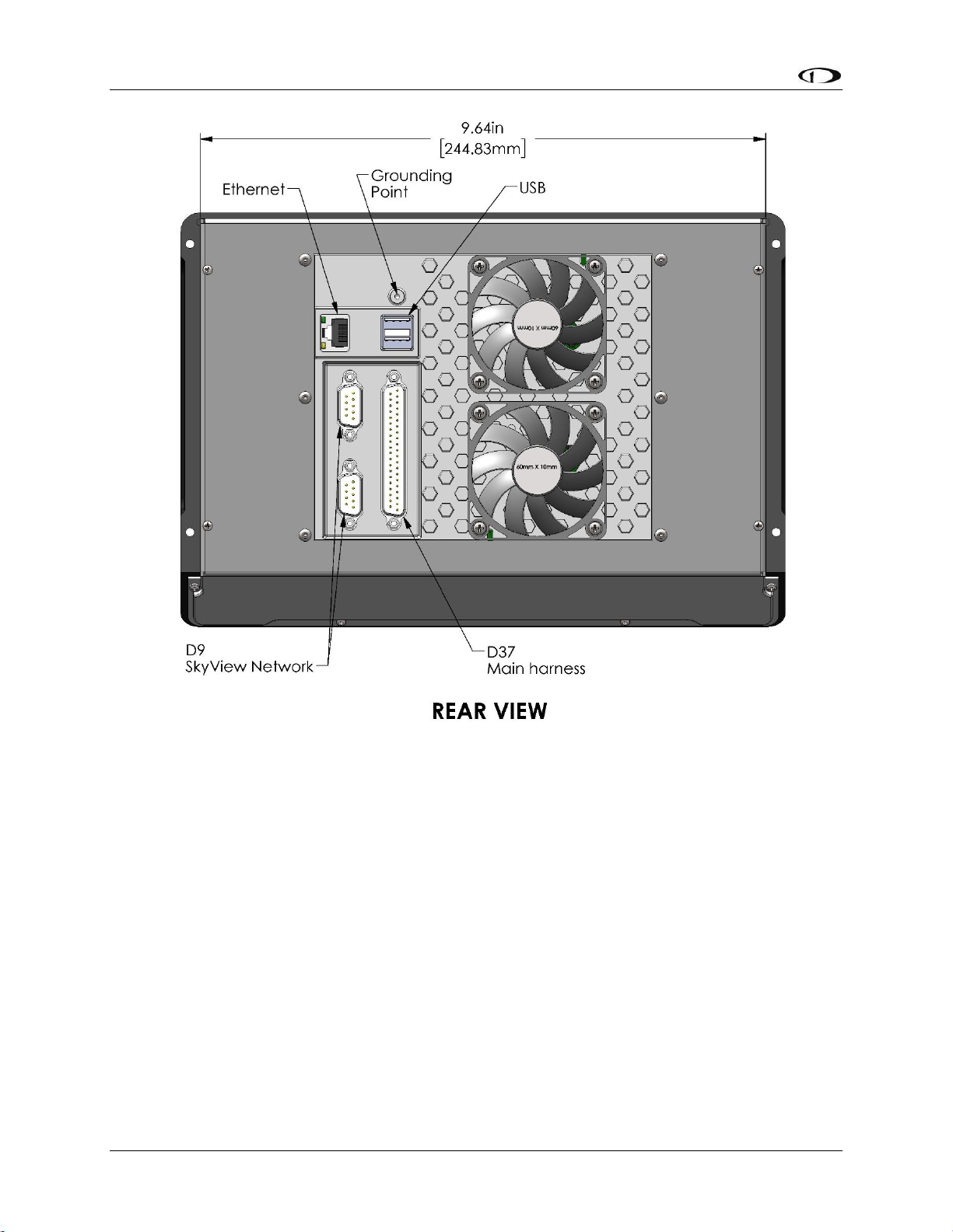
SkyView Display Installation and Configuration
4-14 SkyView System Installation Guide - Revision AA
`
Figure 30 – SV-HDX1100 Rear Dimensions
Page 75
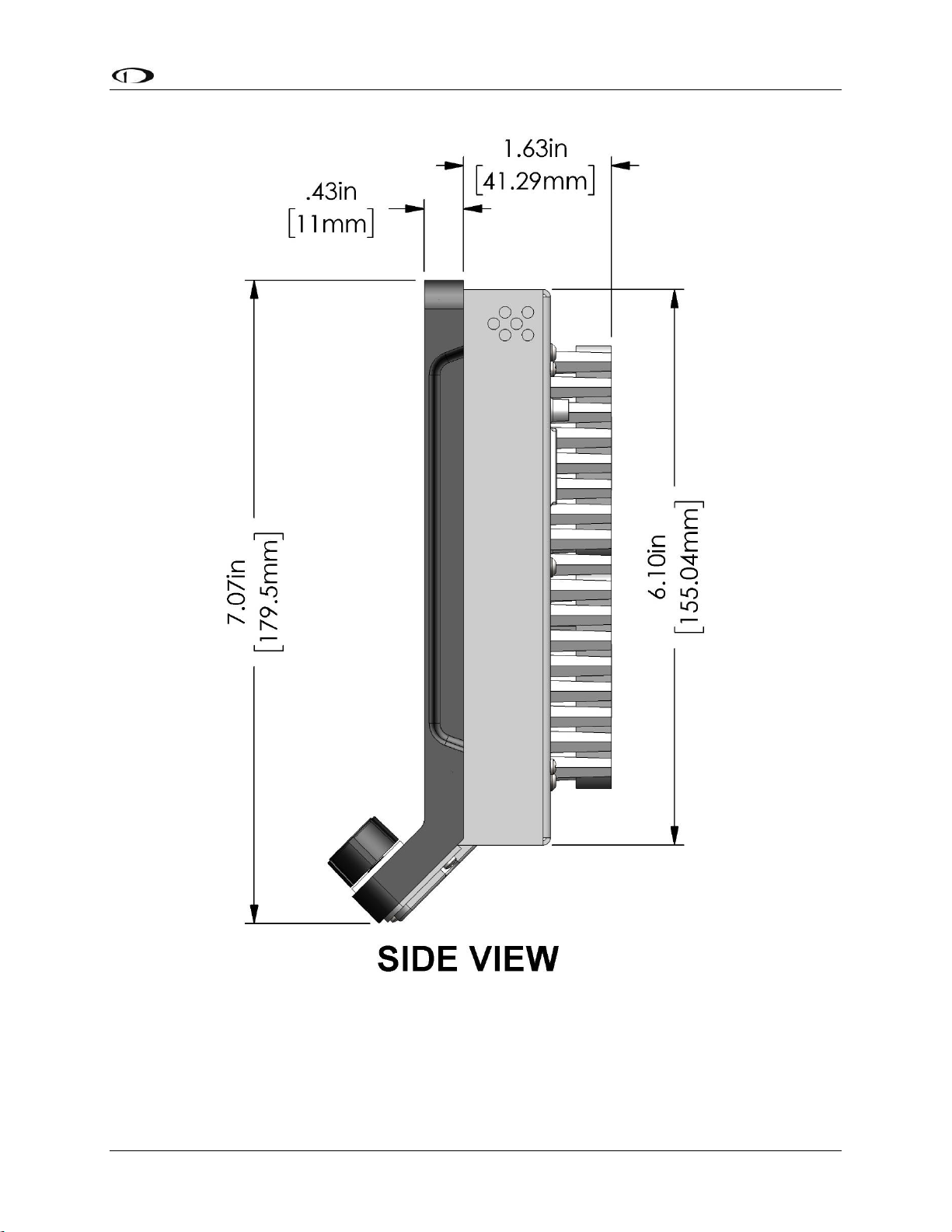
SkyView Display Installation and Configuration
SkyView System Installation Guide - Revision AA 4-15
Figure 31 – SV-HDX1100 Side Dimensions
Page 76

SkyView Display Installation and Configuration
4-16 SkyView System Installation Guide - Revision AA
Figure 32 – HDX1100 Panel Plate
If the SkyView SV-HDX1100 display will be installed into a panel with existing (larger) cutouts
and screw holes for a SkyView SV-D900, SkyView SV-D1000, or SkyView SV-D1000 Touch display
(initial installation or upgrade), a “filler” Panel Plate, and two SkyView Classic / Panel Unit (black
button-head) screws are included with each SkyView SV-HDX1100.
As Figure 32 illustrates, the Panel Plate should be installed from the front of the panel, at the
bottom of the panel cutout where it will be largely covered by the “chin” of the SV-HDX1100.
The Panel Plate is included with SV-HDX1100 units shipped during the first year of production of
the SV-HDX1100 (approximately through year end 2017). If a Panel Plate was not included with
your SV-HDX1100, you can request one from Dynon Avionics Sales – P/N 102897-000.
Page 77
SkyView Display Installation and Configuration
SkyView System Installation Guide - Revision AA 4-17
Electrical Installation
Use this section in conjunction with the information contained in Appendix C: Wiring and
Electrical Connections (notably Figure 217 on page 23-9). The wires and wire colors in this
section refer to the wires on the included SkyView Display Harness (SV-HARNESS-D37).
Some wires that are used in SkyView harnesses are identified with secondary color
stripes. Exposing these striped wires to solvents or abrasives can cause the stripe
color to wear off. Handle these wires with care.
Power Input
SkyView displays have a primary power input that is compatible with 12 volt and 24 volt
electrical systems (10 to 30 volts DC). There are two unterminated solid red primary power
input wires (to reduce current loading in each wire—these are not for redundancy and both
must be connected to the same power source) and two unterminated solid black primary
ground wires.
Ensure that there is an appropriately rated circuit breaker or replaceable fuse on
the primary power input. Reference the Power Section of the System Planning
Section for more information.
Grounding
Ensure that all external devices that interface with SkyView have a common ground with
SkyView. If a device does not share ground with SkyView, it may not communicate properly.
Airplane Master Contactor / Relay Considerations
If your aircraft is equipped with a master contactor or a relay that is operated by the master
switch, it is imperative that the coil of the contactor or relay is protected by a diode to reduce
the voltage spike seen when the contactor is turned off. Without this diode, the aircraft system
can see spikes above 100V, which can damage Dynon Avionics equipment and other avionics.
While some contactors have this diode internally, many do not. Please verify the existence of
this diode before operating your Dynon Avionics equipment. Any diode that is rated for more
than 1A and more than 50V is suitable. Vans Aircraft part number ES DIODE MASTER is also a
suitable option.
SV-BAT-320 Connection and Operation Rules
SkyView displays have the option of an external backup battery - SV-BAT-320. The SV-HARNESSD37 harness has a connector that mates with the connector on the SV-BAT-320. Simply
connecting the display to the battery enables the use of the SV-BAT-320; no additional
configuration is required.
In the event of an electrical failure that causes SkyView to run on the SV-BAT-320, the SV-BAT320 supplies power to the SkyView display it is connected to, along with any devices powered
Page 78
SkyView Display Installation and Configuration
4-18 SkyView System Installation Guide - Revision AA
by the SkyView display – see System Planning, Power . A fully charged SV-BAT-320 can keep
most SkyView systems operating for at least 60 minutes. The SV-BAT-320 does not supply
(backup) power to the following SkyView system devices:
Autopilot servos
Heated AOA/Pitot Probe
SV-ADSB-470
SV-COM-425 / SV-COM-X83
SV-XPNDR-261/262
Trim control servos controlled / powered through the SV-AP-PANEL
Any non-Dynon Avionics device
SkyView displays are only compatible with a Dynon Avionics SV-BAT-320 Backup
Battery. Do not connect a lead-acid battery or any other battery to the connection
reserved for the SV-BAT-320 as the charging algorithm and charging circuitry,
voltages, etc. are optimized for the SV-BAT-320. Connecting any other battery may
have detrimental consequences. Damage caused by connecting such a battery will
not be repaired under warranty.
See the Non-Dynon Avionics Wire Harness Considerations section for important
specifications that must be adhered to for the SV-BAT-320 to charge properly
when used with a non-Dynon Avionics harness.
SkyView Network Connectors
The two D9 connectors on the back of a SkyView display are SkyView network connectors. They
have identical pinouts and are electrically connected inside the display (i.e., they are completely
interchangeable). Installers may use either connector or both connectors in SkyView
installations. Reference Table 115 on page 23-10 for SkyView Network Connector pinout
information.
Note that these connectors are not “RS-232” Serial Port connectors.
Network Setup and Status
Once all SkyView modules are connected in a network, either in a bench top test or permanent
installation, turn the display(s) on. You will see the display boot up and the status LEDs on the
modules light up.
A tail number on the Aircraft Information Page (SETUP MENU > SYSTEM SETUP >
AIRCRAFT INFORMATION) is required for network configuration.
If you have more than one display in your SkyView system, the tail number only
needs to be set on the display that you initially perform the Network Configuration
on. At network configuration time, all other displays that are set to the default tail
Page 79
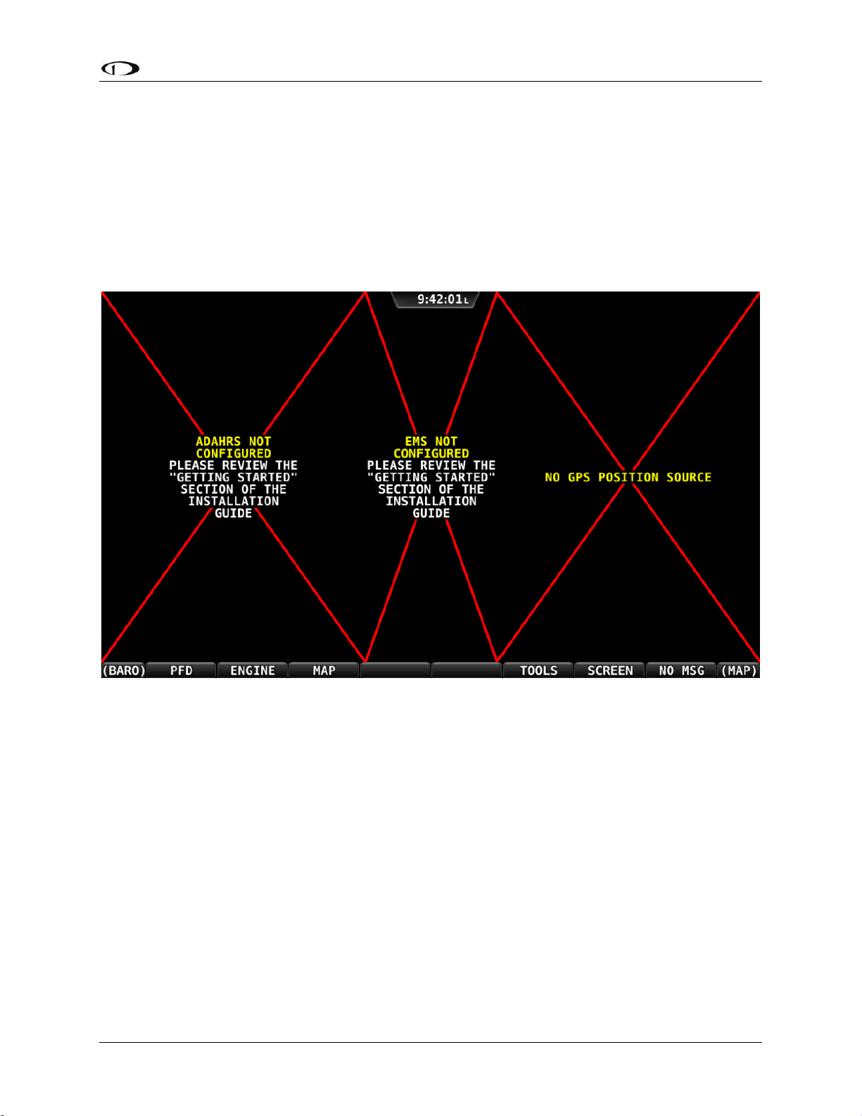
SkyView Display Installation and Configuration
SkyView System Installation Guide - Revision AA 4-19
number of DYNON will automatically have their settings and tail number
synchronized with the display the configuration is performed from. After
configuration, all displays’ tail numbers and settings will be synchronized, and
further setup tasks can be performed from any display.
When you first power up your SkyView display, it will look similar to the screen below (SkyView
HDX and SkyView SE displays will be slightly different). This is normal – you have not yet
performed a SkyView Network Configuration for the SkyView display(s) to recognize your
ADAHRS, EMS, and other SkyView Network modules.
Figure 33 – New SkyView Classic display, SkyView Network not yet configured
Use the following procedure to configure a SkyView network:
1. Push buttons 7+8 to access the SETUP MENU.
2. Navigate to the CONFIGURE… Page (SETUP MENU > SYSTEM SETUP > SKYVIEW NETWORK
SETUP > CONFIGURE…).
3. Press DETECT. A successful network configuration yields the screen in Figure 34 (depending
on the units installed, your SkyView system’s network devices will look different and display
different Software versions).
4. Press FINISH to close the screen and return to the Network Setup Menu.
Page 80

SkyView Display Installation and Configuration
4-20 SkyView System Installation Guide - Revision AA
Figure 34 – Successful SkyView Network Configuration Screen
If the SkyView network is successfully configured, but Software versions on
equipment are not synchronized, you will see a screen that is similar to Figure 35.
Figure 35 – SkyView Network Configuration with Software Update
Page 81

SkyView Display Installation and Configuration
SkyView System Installation Guide - Revision AA 4-21
If you see a screen similar to the one in Figure 35, simply press the button labeled UPDATE to
update the Software running on the equipment in the SkyView network.
To check on SkyView network status, enter the NETWORK STATUS… Menu in the Network
Setup Menu (SETUP MENU > SYSTEM SETUP > SKYVIEW NETWORK SETUP > NETWORK
STATUS…).
The Network Status Page shows all displays, modules, servos, and other Dynon Avionics
products installed on the SkyView network via the D9 SkyView Network connectors. This
includes the following devices: SV-D700 / SV-D1000 / SV-D1000T displays (SkyView) or SV-D600
/ SV-D900 displays (SkyView SE), SV-ADAHRS-200/201 modules, SV-EMS-220/221 modules, SVARINC-429 modules (not supported in SkyView SE), SV-COM-PANEL for SV-COM-C25 and SVCOM-X83 COM radios, SV-AP-PANEL (not supported in SkyView SE) / SV-KNOB-PANEL control
panels, and Dynon Avionics Autopilot Servos. It does NOT include any non-Dynon Avionics
devices or any of the following Dynon Avionics devices that connect via a method other than
SkyView Network: SV-XPNDR-261/262 transponders, SV-ADSB-470 ADS-B receiver (not
supported in SkyView SE), SV-GPS-250/2020 GPS receiver, OAT(s), or individual engine sensors.
SkyView Network has redundancy and error detection features which allow it to detect and
annunciate module and SkyView Network wiring faults. In the event that SkyView reports a
problem with an ADAHRS, EMS module, autopilot servo, or a problem with the “standby
network”, this NETWORK STATUS page will provide more information about the nature of the
problem.
Ethernet Connection
SkyView systems containing more than one display should ideally have their Ethernet ports
connected together for best operation. See the SkyView System Construction section in this
manual for further information about Ethernet.
Internal Time Keeping
Zulu/GMT time is initially obtained from a GPS source. Time is displayed as “--:--:--“until a GPS
fix is received. When a display is turned off, a connected SV-BAT-320 backup battery enables
the display to retain accurate time. To display time, a SkyView display that is not connected to a
SV-BAT-320 must obtain a GPS fix each time it is powered on.
RS-232 Serial Devices
RS-232 serial communication to non-Dynon Avionics devices and interfacing of other devices in
general can be involved and detailed. This installation guide is intended to provide general
installation advice for the most common devices and situations.
A SkyView display includes five general purpose RS-232 serial ports available for use with
compatible equipment. Serial port transmit (TX) and receive (RX) wire sets are twisted together.
Connected RS-232 serial devices must share a common power ground with the SkyView
display(s).
Page 82

SkyView Display Installation and Configuration
4-22 SkyView System Installation Guide - Revision AA
Dynon Avionics devices that use RS-232 serial ports for communication include the SV-GPS250/2020, SV-XPNDR-261 and-262, and SV-ADSB-470. Devices from other manufacturers that
are commonly used with SkyView include transponders (with serial port inputs), NAV radios
such as Garmin SL30, COM radios such as Garmin SL40, GPS devices such as the Garmin X96
series, Vertical Power VP-X, and Emergency Location Transmitters (ELTs). Reference the
appropriate sections of this manual for detailed instructions for installing the SV-GPS-250/2020,
SV-XPNDR-261 and -262, SV-ADSB-470, and Vertical Power VP-X. Additionally, an external serial
device such as a PC or external serial data logger can be connected and used to record real-time
ADAHRS and EMS data that can be output by SkyView.
Serial port 5 is recommended for the SV-GPS-250/2020 connection. Its wire
bundle includes serial transmit, receive, ground, and power, and its wires are
color-matched to the wire colors on the SV-GPS-250/2020.
Transponders with serial altitude input can be directly connected to a display. To interface a
SkyView display to a gray code transponder, the use of a Dynon Avionics Encoder Serial-to-Gray
Code Converter Module (Dynon Avionics P/N 100362-000) is required. Reference the Encoder
Serial-to-Gray Code Converter Section of this guide for more information.
If you have more than one SkyView display, each external serial device’s serial TX wire needs to
be connected to each screen so that it can send information to each display individually.
Information that is received via serial connection is not automatically shared between multiple
SkyView displays in an aircraft. Additionally, if the serial device you are connecting to your
SkyView system can receive information from SkyView, that device’s RX wire must be
connected to all SkyView displays as well. SkyView has special hardware to allow multiple TX
lines to be connected together for redundancy. It is required that all connections to/from a
particular serial device be connected to the same SkyView display serial port on every display in
the SkyView system.
The instructions above specify that both the TX and RX lines from external serial
devices be connected to multiple screens in parallel. SkyView systems that were
installed before SkyView Software v2.6 may require wiring changes to
accommodate this. Specifically, if your system has multiple SkyView displays and
your transponder is utilizing the serial altitude encoder output, the transponder
would have only been connected to one screen when you configured your
SkyView system. As of v2.6, transponders (and other serial devices) must be
connected to all SkyView displays to work correctly.
It is the installer’s responsibility to determine how to connect external serial devices to the
display using the included wire harness. Installers should reference serial device documentation
for serial port specifications. The basic order for installing an external serial device is as follows.
1. Specify a serial port for the device.
2. Make the serial port electrical connection. If you have more than one SkyView display, make
the same connection to all SkyView displays.
Page 83

SkyView Display Installation and Configuration
SkyView System Installation Guide - Revision AA 4-23
3. Configure the serial port (under SETUP MENU > SYSTEM SETUP > SERIAL PORT SETUP)
according to the device’s documentation.
4. When serial port configuration is complete, perform a final check by doing the following:
a. Power down all displays except #1. Verify all serial port devices are working -
transponder, GPS, radios, etc.
b. Power down all displays except #2. Verify all serial port devices are working -
transponder, GPS, radios, etc.
c. Power down all displays except #3. Verify all serial port devices are working -
transponder, GPS, radios, etc.
A SkyView Display serial port can be configured to communicate with one device
on its TX and a different device on its RX, but when doing so, the TX and RX speeds
must be the same.
Table 12 contains serial port wire functions and wire harness colors.
Serial Port
Wire Function
SkyView Display Harness
Wire Colors
1
TX
Brown with Orange stripe
RX
Brown with Violet stripe
2
TX
Yellow with Orange stripe
RX
Yellow with Violet stripe
3
TX
Green with Orange stripe
RX
Green with Violet stripe
4
TX
Blue with Orange stripe
RX
Blue with Violet stripe
5
TX
Gray with Orange stripe
RX
Gray with Violet stripe
SV-GPS-
250/2020 Power
Solid Orange
SV-GPS-
250/2020
Ground
Solid Black
Table 12 – SkyView Serial Port Connections
Traffic Devices
SkyView has the ability to receive and display aircraft traffic data from:
Dynon Avionics SV-XPNDR-261/262 (from TIS)
Dynon Avionics SV-ADSB-470 (from ADS-B)
Garmin GTX 330 / 330ES (from TIS)
Other devices that output traffic data that emulates “Garmin TIS format” including
Garrecht / AIR Avionics TRX-1500 (set to TIS output), NavWorx ADS-B receiver, and
Zaon XRX (set to “Garmin” output). For such devices, configure the SkyView serial port
Page 84

SkyView Display Installation and Configuration
4-24 SkyView System Installation Guide - Revision AA
connected to these devices in SERIAL PORT x SETUP, SERIAL IN DEVICE to GARMIN TIS
TRAFFIC (which will automatically set the associated parameters).
If a device that can provide traffic data is connected to SkyView and configured (usually as a TIS
serial traffic device under SETUP MENU > SYSTEM SETUP > SERIAL PORT SETUP), further traffic
display options can be configured in SETUP MENU > TRAFFIC SETUP. Display of traffic on the
MAP page and the PFD page can be set to:
NONE (Do not display traffic)
TA ONLY (Display only Traffic Advisories [TAs])
ALL (Display ALL traffic)
Only one device can provide traffic information to SkyView at any moment. If you
have more than one device connected to SkyView that is capable of providing
traffic (such as, but not limited to, SV-XPNDR-261/262 (TIS), SV-ADSB-470, Zaon
XRX, etc.), the devices provide traffic information with the following priority,
based on the completeness of the traffic portrait they provide:
1. SV-ADSB-470 with full traffic (ADS-B ground station reporting with radar
coverage)
2. TIS transponder from SV-XPNDR-261/262 or Garmin GTX 330 / ES (when in an
active TIS coverage area)
3. FLARM
4. Zaon
5. SV-ADSB-470 with No RADAR (ADS-B reception, but without ground ADS-B
station coverage or radar target inclusion).
Dynon Avionics SV-XPNDR-261/262 Transponder
See the SV-XPNDR-261/262 Installation and Configuration section for detailed instructions on
how to set up the serial connection to the SV-XPNDR-261/262.
Note that if you are using a Dynon Avionics SV-XPNDR-261/262 Transponder, none of the
encoder options in the below sections should to be set for the Dynon Avionics SV-XPNDR261/262 module to receive pressure altitude. Instead, when the SV-XPNDR-261/262 is set up as
described in the SV-XPNDR-261/262 Installation and Configuration section, it is automatically
configured to receive pressure altitude from SkyView. Alternatively, systems that require the
use of an external altitude encoder can be configured per the following section to have SkyView
pass along an external pressure altitude source.
Dynon Avionics SV-ADSB-470
See Section 14 - SV-ADSB-470 Installation and Configuration for detailed instructions on how to
set up the serial connection to the SV-ADSB-470.
Garmin GTX 330ES
To enable ADS-B traffic with a Garmin GTX 330ES, both the serial port transmit and serial port
receive between SkyView and the GTX 330ES must be connected and configured. The GTX
330ES must be fully configured to output ADS-B Out, which requires a TSO’d GPS position.
Page 85

SkyView Display Installation and Configuration
SkyView System Installation Guide - Revision AA 4-25
Contact Garmin for correctly configuring the GTX 330ES ADS-B Out capability. Also see SVADSB-470 Installation and Configuration for additional configuration.
SETUP MENU > SYSTEM SETUP > SERIAL PORT SETUP > SERIAL PORT x SETUP > SERIAL IN
DEVICE > GARMIN GTX 330ES
SETUP MENU > SYSTEM SETUP > SERIAL PORT SETUP > SERIAL PORT x SETUP > SERIAL OUT
DEVICE > ICARUS ALTITUDE 100ft OR ICARUS ALTITUDE 10ft
SETUP MENU > SYSTEM SETUP > AIRCRAFT INFORMATION > TRANSPONDER HEX CODE >
(set to same HEX CODE as configured in the Garmin 330 ES) > ACCEPT (button).
External Serial Altitude Encoder Support
Some locales may require the use of a certified altitude encoder with the Dynon Avionics SVXPNDR-261/262 Transponder. SkyView supports external serial altitude encoders that use
Icarus/Garmin format. When one is connected, the SV-XPNDR-261/262 uses the external
altitude encoder data source instead of SkyView’s own ADAHRS-generated pressure altitude.
However, the altitude displayed by SkyView on the PFD page is ALWAYS sourced from SkyView
ADAHRS data.
To have SkyView use an external altitude serial encoder as the pressure altitude source for the
SV-XPNDR-261/262:
Wire a SkyView serial receive line to the respective serial transmit connection from the
serial altitude encoder. If you have more than one SkyView display, make the same
connection to all SkyView displays.
Ensure there is a shared ground between the SkyView display and the serial altitude
encoder. If you have more than one SkyView display, make the same connection to all
SkyView displays.
Configure this serial port on each display under SETUP MENU > SYSTEM SETUP > SERIAL
PORT SETUP. The SERIAL IN device for this serial port should be set to ICARUS/GARMIN
ALTITUDE.
Non-Dynon Avionics Transponder Serial Altitude Encoder Output
To use SkyView’s altitude output functionality with your transponder that can receive serial
altitude input:
Wire a SkyView serial transmit line to the respective receive connection on the transponder.
If you have more than one SkyView display, make the same connection to all SkyView
displays.
Ensure there is a shared ground between the SkyView display and the transponder. If you
have more than one SkyView display, make the same connection to all SkyView displays.
Configure the serial port on each display appropriately. There is an example serial port
configuration on 4-38.
SkyView Altitude Encoder Output Formats
Page 86

SkyView Display Installation and Configuration
4-26 SkyView System Installation Guide - Revision AA
There must be a SkyView ADAHRS installed for the altitude encoder output to
function.
SkyView outputs its altitude measurements in two different formats. You can use either format
on any of the serial ports. These formats are described in Table 13 and Table 14. SkyView will
function properly whether or not this altitude encoder functionality is used.
ICARUS
Used by
Garmin GTX330/ES (Garmin serial port must be set to Icarus input),
Garmin GTX327 (Garmin serial port must be set to Icarus input),
Garmin GTX328 (Garmin serial port must be set to Icarus input),
Icarus,
Trimble
Baud rate
9600
Format
ALT, space, five altitude bytes, carriage return
Example message
ALT 05200[CR]
Table 13 – Icarus Format
DYNON AVIONICS CONVERTER
Used by
Dynon Avionics Encoder Serial-to-Parallel Converter,
Garmin AT (formerly UPS Aviation Technologies)
Garmin SL70 (same unit as Garmin AT)
Baud rate
1200
Format
#AL, space, +/-sign, five altitude bytes, T+25, checksum, carriage return
Example message
#AL +05200T+25D7[CR]
Table 14 – Dynon Avionics Serial-to-Gray Code Converter Format
Per ATC/FAA requirements, SkyView’s serial encoder output reports pressure altitude, which,
by definition, is indicated altitude when the baro is set to 29.92. Thus, when you set SkyView’s
baro adjustment to 29.92, its indicated altitude will match the altitude that is being reported to
your transponder.
Non-Dynon Avionics Transponder Serial Input Installation
SkyView can display the status of the Garmin GTX 327 and Garmin GTX 330 / 330ES
transponders. To use this functionality with SkyView:
Wire a serial receive line to the respective transmit line on the transponder. If you have
more than one SkyView display, make the same connection to all SkyView displays.
Ensure there is a shared ground between the SkyView display and the transponder. If you
have more than one SkyView display, make the same connection to all SkyView displays.
Page 87

SkyView Display Installation and Configuration
SkyView System Installation Guide - Revision AA 4-27
Configure the serial port on each display appropriately under SETUP MENU > SYSTEM SETUP
> SERIAL PORT SETUP.
Configure the serial port on the transponder appropriately. For a Garmin GTX 327, 330 / ES,
the RS-232 output of the appropriate serial port on the transponder should be set to
REMOTE+TIS.
Gray-Code Transponder Installation
To use SkyView’s altitude encoder functionality with your Gray Code transponder:
Follow the installation instructions in the Gray-Code Transponder Installation Section. If you
have more than one SkyView display, make the same connection(s) to all SkyView displays.
Configure the serial port on each display according to the instructions on page 15-7.
Reference the Serial Port Configuration Section of this guide for serial port configuration
information.
Garmin SL30 COM / NAV Radio
In addition to the NAV radio functions of the SL30, SkyView can display COM radio information
from the SL30 on the top bar of the SkyView display(s) and send COM frequencies to the SL30
(TUNE COM).
Connect SL30 serial RX pin 4 (RxD1) to a SkyView serial TX. If you have more than one
SkyView display, make the same connection to all SkyView displays.
Connect SL30 serial TX pin 5 (TxD1) to a SkyView serial RX. If you have more than one
SkyView display, make the same connection to all SkyView displays.
Ensure there is a shared ground between the SkyView display and the SL30. If you have
more than one SkyView display, make the same connection to all SkyView displays.
Configure the serial port on the SL30 appropriately. On the SL30, the Indicator Head Type
should be set to NONE.
On SkyView
SETUP MENU > SYSTEM SETUP > SERIAL PORT SETUP > SERIAL PORT x SETUP > SERIAL IN
DEVICE > GARMIN / APOLLO SL30. This will automatically set the SERIAL IN/OUT BAUD RATE
and SERIAL OUT DEVICE.
Set SERIAL IN FUNCTION TO NAV 1, 2, 3, or 4. If the SL30 is the only NAV device, select NAV
1.
Set NAVIGATION SOURCE DISPLAY NAME: (user selectable, 7 characters, suggest SL30). The
name entered here is displayed as the HSI source and the Flight Plan Source (if this device
outputs a flight plan).
If you wish the SL30 frequency and status to be displayed on the top bar:
SETUP MENU > SYSTEM SETUP > DISPLAYED COM > GARMIN / APOLLO SL30 (PORT x)
and
SETUP MENU > SYSTEM SETUP > DISPLAY COM IN TOP BAR: YES
Page 88

SkyView Display Installation and Configuration
4-28 SkyView System Installation Guide - Revision AA
Val Avionics NAV 2000
To work with SkyView, the NAV 2000 must have v1.10 Software (minimum). The Software
version is displayed during the NAV 2000 startup.
Connect NAV 2000 serial RX Pin 4 (Connector P1) to a SkyView serial TX. If you have more
than one SkyView display, make the same connection to all SkyView displays.
Connect NAV 2000 serial TX Pin 5 (Connector P1) to a SkyView serial RX. If you have more
than one SkyView display, make the same connection to all SkyView displays.
Ensure there is a shared ground between the SkyView display and the NAV 2000 – Serial
Ground Pin 3 (Connector P1). If you have more than one SkyView display, make the same
connection to all SkyView displays.
Configure the NAV 2000:
Enter the config page by pressing and holding both the left and right knobs while the unit is
starting up until the display shows the last used active frequency and the first config page:
o *A108.00 Rs I:xxx (the *x*'s are a placeholder for the resolver setting)
Rotate the left inner (small) encoder to show *Non* in the section following *Rs I:
Push and hold both encoder buttons to exit from the configuration pages
On SkyView
SETUP MENU > SYSTEM SETUP > SERIAL PORT SETUP > SERIAL PORT x SETUP > SERIAL IN
DEVICE > VAL AVIONICS NAV 2000. This will automatically set the SERIAL IN/OUT BAUD
RATE and SERIAL OUT DEVICE.
Set SERIAL IN FUNCTION TO NAV 1, 2, 3, or 4. If the NAV 2000 is the only NAV device, select
NAV 1.
Set NAVIGATION SOURCE DISPLAY NAME: (user selectable, 7 characters – suggest
NAV2000). The name entered here is displayed as the HSI source and the Flight Plan Source
(if this device outputs a flight plan).
SETUP MENU > SYSTEM SETUP > DISPLAYED COM: NONE (If a SkyView compatible COM
radio such as the SV-COM-C25 is installed, refer to those instructions for this setting).
and
SETUP MENU > SYSTEM SETUP > DISPLAY COM IN TOP BAR: NO (If a SkyView compatible
COM radio such as the SV-COM-C25 is installed, refer to those instructions for this setting).
Garmin SL40 COM Radio
SkyView can display COM radio information from the SL40 on the SkyView top bar and send
COM frequencies to the SL40 (TUNE COM).
Connect SL40 serial RX pin 10 (RxD1) to a SkyView serial TX. If you have more than one
SkyView display, make the same connection to all SkyView displays.
Connect SL40 serial TX pin 3 (TxD1) to one of the SkyView serial RX pins on each display. If
you have more than one SkyView display, make the same connection to all SkyView
displays.
Ensure there is a shared ground between the SkyView display, and the SL40. If you have
more than one SkyView display, make the same connection to all SkyView displays.
Configure the serial port on the SL40 appropriately.
Page 89

SkyView Display Installation and Configuration
SkyView System Installation Guide - Revision AA 4-29
Configure the serial port: SETUP MENU > SYSTEM SETUP > SERIAL PORT SETUP > SERIAL
PORT x SETUP > SERIAL IN DEVICE > GARMIN / APOLLO SL40. This will automatically set the
SERIAL IN FUNCTION, SERIAL IN/OUT BAUD RATE, and SERIAL OUT DEVICE.
Set the SL40 status to be displayed on the top bar: SETUP > SYSTEM SETUP > DISPLAYED
COM > GARMIN / APOLLO SL40 (PORT x)
and
SETUP MENU > SYSTEM SETUP > DISPLAY COM IN TOP BAR: YES
Trig TY91 COM Radio
SkyView can display COM radio information from the TY91 on the top bar of the SkyView
display(s) and “push” COM frequencies to the TY91 (TUNE COM).
Connect TY91 RS232 In (TC90 Pin 6) to a SkyView serial TX. If you have more than one
SkyView display, make the same connection to all SkyView displays.
Connect TY91 RS232 Out (TC90 Pin 5) to a SkyView serial RX. If you have more than one
SkyView display, make the same connection to all SkyView displays.
Ensure there is a shared ground between the SkyView display and the TY91. If you have
more than one SkyView display, make the same connection to all SkyView displays.
On the TY91, configure the serial port appropriately (per Trig’s documentation).
On SkyView
SETUP MENU > SYSTEM SETUP > SERIAL PORT SETUP > SERIAL PORT x SETUP > SERIAL IN
DEVICE > TRIG TY91. This will automatically set the SERIAL IN FUNCTION, SERIAL IN/OUT
BAUD RATE, and SERIAL OUT DEVICE.
SETUP MENU > SYSTEM SETUP > PRIMARY COM > TRIG TY91 (PORT x)
SETUP MENU > SYSTEM SETUP > DISPLAY COM IN TOP BAR > YES
Icom IC-A210 COM Radio
The IC-A210 does not transmit status or frequencies via serial port, so IC-A210 information
cannot be displayed on the top bar of the SkyView display(s). SkyView can send COM radio
frequencies to the IC-A210 (TUNE COM).
Confirm that your A210 is running Software version 1.53 or newer. This feature will not
work with old Software. Contact Icom for details on upgrading your radio Software.
Connect IC-A210 serial RX (Molex Pin 2 / D15 Pin 10) to a SkyView serial TX. If you have
more than one SkyView display, make the same connection to all SkyView displays.
Ensure there is a shared ground between the SkyView display and the IC-A210. If you have
more than one SkyView display, make the same connection to all SkyView displays.
On the IC-A210, configure the serial port appropriately (per Icom documentation).
On SkyView
SETUP MENU > SYSTEM SETUP > SERIAL PORT SETUP > SERIAL PORT x SETUP > SERIAL IN
DEVICE > ICOM A210. This will automatically set the SERIAL IN FUNCTION, SERIAL IN/OUT
Page 90

SkyView Display Installation and Configuration
4-30 SkyView System Installation Guide - Revision AA
BAUD RATE, and SERIAL OUT DEVICE. (Although there is no IC-A210 serial TX to SkyView
serial RX connection, SERIAL IN DEVICE must be configured as described.)
SETUP MENU > SYSTEM SETUP > PRIMARY COM > ICOM A210 (PORT x)
and
SETUP MENU > SYSTEM SETUP > DISPLAY COM IN TOP BAR > NO
MGL Avionics V6/V10 COM Radio
The V6 and V10 do not transmit status or frequencies via serial port, so V6/V10 information
cannot be displayed on the top bar of the SkyView display(s). SkyView can send COM radio
frequencies to the V6/V10 (TUNE COM).
Connect V6/V10 RS232 DATA1 - IN (D25 Pin 3) to a SkyView serial TX. If you have more than
one SkyView display, make the same connection to all SkyView displays.
Ensure there is a shared ground between the SkyView display and the V6/V10. If you have
more than one SkyView display, make the same connection to all SkyView displays.
On the V6/V10, configure the serial port appropriately (per MGL Avionics’ documentation).
On SkyView
SETUP MENU > SYSTEM SETUP > SERIAL PORT SETUP > SERIAL PORT x SETUP > SERIAL IN
DEVICE > MGL V6/V10. This will automatically set the SERIAL IN FUNCTION, SERIAL IN/OUT
BAUD RATE, and SERIAL OUT DEVICE. (Although there is no V6/V10 serial TX to SkyView
serial RX connection, SERIAL IN DEVICE must be configured as described.)
SETUP MENU > SYSTEM SETUP > PRIMARY COM > MGL V6/V10 (PORT x)
and
SETUP MENU > SYSTEM SETUP > DISPLAY COM IN TOP BAR > NO
f.u.n.k.e. Avionics ATR833 8.33 kHz-capable COM Radio
Garmin GTR 200
Garmin GTR 225 COM Radio
Garmin GNC 255 COM Radio / NAV Receiver
SkyView can send frequencies to the GNC 255’s standby frequency.
On the GNC 255:
Connect GNC 255 P2001 Pin 16 to a SkyView serial TX. If you have more than one
SkyView display, make the same connection to all SkyView displays.
Connect GNC 255 P2001 Pin 1 to a SkyView serial RX. If you have more than one
SkyView display, make the same connection to all SkyView displays.
Ensure there is a shared ground between the SkyView display and the GNC 255. If you
have more than one SkyView display, make the same connection to all SkyView displays.
On the GNC 255, configure the serial port:
o Set “I/O Mode” to “NMEA”
o Set “CDI Indicator” to “NONE”
Page 91

SkyView Display Installation and Configuration
SkyView System Installation Guide - Revision AA 4-31
On SkyView:
SETUP MENU > SYSTEM SETUP > SERIAL PORT SETUP > SERIAL PORT x SETUP > SERIAL IN
DEVICE > GARMIN GNC 255 A/B. This will automatically set the SERIAL IN/OUT BAUD
RATE, and SERIAL OUT DEVICE.
SETUP MENU > SYSTEM SETUP > SERIAL PORT SETUP > SERIAL PORT x SETUP > SERIAL IN
FUNCTION > NAV 1.
Trig Avionics TY91 and TY92 COM Radio10
SkyView can display COM radio information from the ATR833, GTR 200, GTR 225, GNC 255,
TY91, and TY92 on the SkyView top bar and send COM frequencies to them (TUNE COM).
Note that SkyView does not send database information for the GTR 200 to enable the GTR
200’s “Nearest or Flight Plan Airports” feature.
Connect the radio’s serial RX to a SkyView serial TX. If you have more than one SkyView
display, make the same connection to all SkyView displays.
Connect the radio’s serial TX to one of the SkyView serial RX pins on each display. If you
have more than one SkyView display, make the same connection to all SkyView displays.
Ensure there is a shared ground between the SkyView display, and the radio. If you have
more than one SkyView display, make the same connection to all SkyView displays.
Configure the serial port on the radio appropriately.
Configure the serial port: SETUP MENU > SYSTEM SETUP > SERIAL PORT SETUP > SERIAL
PORT x SETUP > SERIAL IN DEVICE >
FUNKE ATR833 or
GARMIN GTR 200 or
GARMIN GNC 255 A/B or
GARMIN GTR 225 A/B or
TRIG TY9X 25KHz ONLY
TRIG TY9X 8.33/25KHz
This will automatically set the SERIAL IN FUNCTION, SERIAL IN/OUT BAUD RATE, and SERIAL
OUT DEVICE.
Set the radio status to be displayed on the top bar: SETUP > SYSTEM SETUP > DISPLAYED COM >
(device you chose above) (PORT x)
and
SETUP MENU > SYSTEM SETUP > DISPLAY COM IN TOP BAR: YES
Emergency Location Transmitter (ELT)
SkyView can provide a GPS data stream to ELTs that accept GPS data in NMEA format.
Wire a serial transmit (TX) line from one display to the receive (RX) line on the ELT. If you
have more than one SkyView display, make the same connection to all SkyView displays.
Ensure there is a shared ground between the SkyView display and the ELT. If you have more
than one SkyView display, make the same connection to all SkyView displays.
10
Full TY91/92 8.33 kHz support depends on a future software update from Trig.
Page 92

SkyView Display Installation and Configuration
4-32 SkyView System Installation Guide - Revision AA
Configure the SkyView display serial port:
SETUP MENU > SYSTEM SETUP > SERIAL PORT SETUP > SERIAL PORT x SETUP
SERIAL IN DEVICE: (don’t care, does not affect ELT)
SERIAL IN/OUT BAUD RATE: (set to match speed of ELT; typically 4800 or 9600)
SERIAL OUT DEVICE: NMEA OUT (BASIC)
Dynon Avionics ADAHRS / EMS / SYSTEM / NMEA (GPS) Data Outputs
To output real-time data to an external serial device, such as a serial data logger or other device
that accepts NMEA or Dynon Avionics formats:
Wire a serial transmit line from one display to the receive line on the external serial device.
If you have more than one SkyView display, make the same connection to all SkyView
displays.
Ensure there is a shared ground between the SkyView display and the external serial device.
If you have more than one SkyView display, make the same connection to all SkyView
displays.
Configure the serial port on the display appropriately under SETUP MENU > SYSTEM SETUP
> SERIAL PORT SETUP, SERIAL PORT x SETUP > selecting the desired output data format.
TIS Format Traffic Output
SkyView can be configured to output TIS format traffic information for external display on other
avionics that can receive traffic in TIS format. When this option is selected, only the actual TIS
traffic from a SV-XPNDR-261/262 is included in this serial data stream. This stream does not
include ADS-B, FLARM, Zaon, or other traffic sources that may be available to SkyView.
Wire a serial transmit line from one display to the receive line on the external serial device.
If you have more than one SkyView display, make the same connection to all SkyView
displays.
Ensure there is a shared ground between the SkyView display and the external serial device.
If you have more than one SkyView display, make the same connection to all SkyView
displays.
Configure the serial port on the display appropriately under SETUP MENU > SYSTEM SETUP
> SERIAL PORT SETUP, SERIAL PORT x SETUP > TIS OUT (330 FORMAT).
USB Usage and Accessibility
It is useful to have the USB socket on the display’s wire harness accessible after
installation for file uploads and downloads.
The USB connector is used during the following operations:
System Software updates
Configuration file uploads and downloads
Database updates
Page 93
SkyView Display Installation and Configuration
SkyView System Installation Guide - Revision AA 4-33
External Dim Control (Dimming) Connections
DIM INPUT (Pin 25) The backlight level on a SkyView display can be increased or decreased
using a varying DC voltage of 0 to 36 volts DC, such as provided by the Dynon Avionics SVKNOB-DIMMER – see Accessory Installation and Configuration, SV-KNOB-DIMMER for details.
See Display Setup, External Brightness Management later in this section to configure brightness
levels for specific voltages.
DIM OUTPUT (Pin 26) The DIM OUTPUT signal is an approx. 120 Hz (may change in future
Software revisions) Pulse Width Modulation (PWM) signal directly proportional to the screen
brightness – 100% to 0.02%. This output is designed to directly control the dim level of devices
such as LEDs; a common use is for the back-lighting of switches in a panel so that they dim at
night in conjunction with SkyView’s automatic dim levels.
The DIM OUTPUT (Pin 26) signal is an open collector to ground - it acts as a switch to ground,
and does not source any power itself. Pin 26 can sink a maximum current of 120mA and a
maximum voltage of 40V. The DIM OUTPUT signal is not analog and cannot be used to control
the dim level of devices that expect 0-5V, 0-12V, or a resistance as their dimming input.
Do not connect the DIM OUTPUT (Pin 26) signal from multiple SkyView screens in parallel. The
DIM OUTPUT signals from each display is not synchronous, and this will lead to inconsistent
behavior.
Audio Output Electrical Connections
Dynon Avionics recommends that SkyView’s audio outputs be connected to an
unmuted input on your audio panel or intercom. When connected this way, critical
audio alerts generated by SkyView are not muted by ATC transmissions or other
audio events that could cause SkyView’s audio to be suppressed if it were
connected to a muting input.
SkyView’s audio output cannot be connected in parallel with a radio to a headset.
Doing so will significantly reduce the volume of the radio output, possibly to the
level that it is not usable. An intercom such as the SV-INTERCOM-2S, audio mixer,
or audio panel is required to utilize this output.
If you are converting a Dynon Avionics D10/D100 product installation to a SkyView
installation, you should remove the variable resistor that is connected to the
existing audio output wiring: SkyView’s audio output (volume) is adjustable.
The audio outputs on pins 13 and 31 (left and right, respectively) of the display’s D37 connector
can drive audio panel or intercom auxiliary inputs. When interfaced with such devices, they can
generally be used with any input designated as an auxiliary input without any external resistors
or other components needed between the SkyView and the intercom.
Use left and right audio outputs for stereo mode. If the audio panel or intercom only supports
mono input, short the left and right audio outputs together and connect them to the mono
input on the device. To minimize noise, ensure that your SkyView audio ground and intercom or
Page 94

SkyView Display Installation and Configuration
4-34 SkyView System Installation Guide - Revision AA
audio panel ground are directly connected together, even though they nominally share a
common ground via other aircraft wiring (audio ground is pin 30 on the D37).
If there is more than one display on a SkyView network, you MUST connect all displays’ audio
outputs to the same audio panel input to ensure that audio is always heard. Electrically short
the respective left and right outputs together for stereo mode (i.e., left-to-left and right-toright) or connect all audio outputs together for mono mode. The same rule applies for audio
grounds.
To minimize the possibility of audio “humming”, a 16 AWG wire may optionally be
connected between the ground point for the intercom/audio panel/radio(s) and
SkyView display case(s). To attach the wire to the rear of the SkyView display, a 4-
40 x 3/16” long screw may be screwed into the threaded boss above the USB ports
on the back of the SkyView display.
Audio output volume will be controlled via the interface on a SkyView display, so no external
hardware components are required. The audio output from SkyView has a maximum output of
10V p-p with 50 Ω (50 ohms) of source impedance.
SkyView systems with more than one display normally only output audio alerts from one
display to minimize audio distortion. In a SkyView system that has more than one display and
dual SV-EMS-220s/221s to monitor dual engines, EMS audio alerts are enabled from two
displays. At moments when two displays are outputting EMS audio alerts, there may be minor
“doubling” of audio alerts heard in the audio system.
Page 95
SkyView Display Installation and Configuration
SkyView System Installation Guide - Revision AA 4-35
SkyView Audio Output Settings
Go to SETUP MENU > SYSTEM SETUP > AUDIO SETUP to configure audio output settings. Most
of the items in this menu control whether the audio output for a particular alert or alert
category is played or not. The settings that can be adjusted here that are not voice alert toggles
are:
VOLUME CONTROL / TEST – Sets the volume level. While in this menu, sound is played
continuously so that proper audio connectivity and volume levels can be confirmed.
o In this menu only, audio is only outputted from the actual display that is in the setup
menu. This allows one to troubleshoot the physical audio connections. In actual
operation, only one of the displays transmits audio at a time. Which display happens
to be transmitting is automatically managed by SkyView. Since all displays’ audio
outputs are connected together (and to the intercom or audio panel), this is
transparent in actual use.
BOOT SOUND – When set to ON, the system will say “Dynon Avionics SkyView” when it first
starts up.
ANGLE OF ATTACK – This sets a pulsing, progressive tone that increases in frequency, similar
in nature to a conventional reed type aircraft stall warning sound to a reed-type stall
warning sound, although it is much more predictable in its progression. It can be set to start
its pulsing tones at either the border of the yellow/green marks on the AOA bars, the
middle of the yellow, or the yellow/red border. The pulsing tones start at the level selected
and get progressively quicker and closer together until a solid tone is played at critical AOA
(in the red.)
o INHIBIT AOA BELOW AIRSPEED – Allows you to set an airspeed below which no AOA
tones are played. This helps prevent nuisance alarms while on the ground and
taxiing, especially in tail draggers.
Contact Inputs
Contact Input #1 – (Optional) External LEVEL Button. See the Autopilot section for detailed
explanation.
Contact Input #2 – (Optional) External GO AROUND Button. See the Autopilot section for
detailed explanation.
External GO AROUND Button is not supported in SkyView SE. If you intend to install
and use SkyView SE, do not purchase or install an External GO AROUND Button.
Contact Input #3 and #4 are currently not supported. A future Software update may enable this
functionality. Do not connect anything to these pins at this time.
Reserved Connections for Future Use
Do not connect anything to unspecified D37 connector pins (directly or using the display
harness). These pins are reserved for future use.
Page 96

SkyView Display Installation and Configuration
4-36 SkyView System Installation Guide - Revision AA
Display Setup
You can access important information about a SkyView display as well as configure serial ports,
characterize your display backlight behavior and specify other display-specific settings.
How to Access Display Hardware Information
Enter the Display Hardware Information Page (SETUP MENU > LOCAL DISPLAY SETUP > DISPLAY
HARDWARE INFORMATION) to access important display hardware information. This menu
contains status information only—nothing on it is configurable. Reference the Operation
Section of this guide for more information about this menu.
Serial Port Configuration
Reference serial device documentation for serial communication specifications.
SkyView serial ports are configured in the Serial Port Setup Menu (SETUP MENU > SYSTEM
SETUP > SERIAL PORT SETUP). SkyView serial ports have four parameters that must be defined:
Input Device
Input Function
Baud Rate
Output Device
Note that sometimes a parameter will be defined as NONE on the screen. For
example, when a serial port is configured as only an output, the input device and
input function will both be set to NONE.
Input Device
Set the input device to the data format the SkyView display should expect from an input device.
The configurable options list contains equipment by brand and model and also generic data
formats such as NMEA and aviation. NMEA is the standard format for most GPS units (including
the SV-GPS-250). Aviation is used by some Garmin and Bendix/King panel mount equipment. If
your specific equipment is listed by brand and model, we recommend you configure SkyView to
use this option instead of a generic data format.
If you have any ARINC-429 devices, these are configured separately. See the SV-ARINC-429
Installation and Configuration Section of this guide for more information.
Input Function
SkyView has several options for input functions: NONE, GPS, NAV, or POS. Set the device’s input
function to NONE if it does not have an input function.
Page 97

SkyView Display Installation and Configuration
SkyView System Installation Guide - Revision AA 4-37
GPS devices provide GPS position and navigational information. These devices are generally
"moving maps" that depict airports, airspaces, etc., and can generate flight plans. They
provide source data for the moving map, HSI, autopilot, synthetic vision, and the clock in
the Top Bar. An example GPS device is a Garmin X96.
NAV devices provide radio-based navigational information from a VOR or ILS. They provide
source data for the HSI and autopilot. SkyView currently supports only the Garmin SL30 NAV
Radio.
POS devices provide only positional information. These are generally simple GPS receivers
which cannot do flight planning. They provide source data for the moving map, synthetic
vision, and the clock in the Top Bar. Note that a POS device does not provide any data for
the HSI and will not appear in the HSI NAVSRC rotation. An example POS device is the Dynon
Avionics SV-GPS-250/2020.
Input Function Considerations and Priorities
SkyView’s Moving Map Page uses POS and GPS sources for its data. Regardless of the number
of data sources in your system, this page prioritizes these sources and fails over to them as
follows:
POS 1 GPS 1GPS 2GPS 3GPS 4POS 2POS 3POS 4
For example, if your system has one SV-GPS-2020 configured as POS 1 and a Garmin 396
configured as GPS 1, the Moving Map will always use the SV-GPS-2020 as its primary data
source. If the SV-GPS-2020 fails or you configure its input function to NONE, the Moving Map
Page will use the Garmin 396 (or other GPS source) configured as GPS 1 as its primary data
source.
The SkyView HSI uses GPS and NAV sources for its overlays and the user must choose the
source during operation.
SkyView’s internal Navigation Mapping System can generate navigation
information which can be displayed on the HSI. The Navigation Mapping System
requires GPS data, which is sourced from the active (highest priority in the above
list) POS or GPS source. Regardless of what source is being used for position
information, the navigation provided by the Navigation Mapping System is always
the SKYVIEW source on the HSI.
Baud Rate
Set this to match the baud rate of the serial device that is connected to the serial port. SkyView
supports the following baud rates: 1200, 2400, 4800, 9600, 19200, 38400, 57600, and 115,200.
Note that if you use a serial port for a split function (e.g., GPS in and altitude encoder out), the
input and output devices must use the same baud rate.
Output Device
Set output device to the data format the serial device should expect from the SkyView display
(e.g., ICARUS (10ft)).
Page 98

SkyView Display Installation and Configuration
4-38 SkyView System Installation Guide - Revision AA
Example SkyView Serial Port Configuration for Icarus-Compatible Transponder
This example assumes that an Icarus format compatible transponder has been installed on
serial port 1.
1. Enter the Serial Port 1 Setup Menu (SETUP MENU > SYSTEM SETUP > SERIAL PORT SETUP >
SERIAL PORT 1 SETUP).
2. Set serial 1 input device to NONE (SERIAL 1 IN DEVICE: NONE).
3. Set serial 1 in function to NONE (SERIAL 1 IN FUNCTION: NONE).
4. Set serial 1 baud rate to 9600 (SERIAL 1 IN/OUT BAUD RATE: 9600)
5. Set serial 1 output device to ICARUS (100ft) or ICARUS (10ft) (SERIAL 1 OUT DEVICE: ICARUS
(100ft) or ICARUS (10ft).
6. Press BACK or EXIT to save the settings.
Brightness Setup
Enter the Brightness Setup Page (SETUP MENU > LOCAL DISPLAY SETUP > BRIGHTNESS SETUP)
to characterize the display’s backlight behavior. The backlight level can be adjusted manually by
the user (not supported in SkyView SE), automatically by the display based on ambient light
conditions, or by an external control signal while on the Brightness Setup Page and in normal
flight. Regardless of the specified control method, users always have the option of manually
adjusting the backlight level in the Dim Menu.
Automatic Brightness Management
To set the backlight level so that it automatically adjusts, set BRIGHTNESS SOURCE to INTERNAL
(ZERO OFFSET) or INTERNAL (LAST) depending on whether you want the brightness setting to
reset when SkyView is started, or you want the bright setting from SkyView’s last use to be
used when SkyView is started. When this option is selected, dimming is normally controlled
automatically via ambient light detection, but it can also be controlled manually by using the
DIM Menu. Dynon Avionics has created a default dimming profile that should work well in most
aircraft. If you find that this profile does not work well in your installation, it can be customized
to suit your preferences using the tools on the BRIGHTNESS SETUP Menu. This menu displays
several parameters, which are listed and briefly explained below.
LOCAL BRIGHTNESS SENSOR – This is an integer value ranging from 0 to 999 that represents
the amount of light sensed by the display’s integrated light sensor. Use this value to
characterize the ambient light levels in your installation during characterization.
BRIGHTNESS TARGET – This is a percentage ranging from 0% to 100% that represents the
calculated target backlight level based on the sensed ambient light level and the percent
brightness sensor value map. The actual brightness never drops below 20% when the
Brightness Setup Page is displayed, even though the target value may be below 20%.
Page 99

SkyView Display Installation and Configuration
SkyView System Installation Guide - Revision AA 4-39
xx% Brightness Sensor Value – There are four percent brightness sensor values: 25%, 50%,
75% and 100%. These values are correlated to a user-specified brightness sensor value,
which are to the right of the percent value. These percentages along with the minimum
brightness sensor value (explained below) form the calibration points for the backlight
management profile. When the current brightness sensor value matches one of these
points, the target backlight level is adjusted to its matching percentage. When the current
brightness sensor value is in between these points, the display interpolates between the
points and calculates an appropriate target backlight level. These values must be set by the
user.
MINIMUM BRIGHTNESS SENSOR VALUE – This is an integer value ranging from 0 to 999 that
represents the smallest amount of light that is expected to be sensed by the integrated light
sensor. This must be set by the user.
RESET TO DYNON AVIONICS DEFAULTS – (If needed) Use this option to start over.
Press the ACCEPT button to save any changes you make.
External Brightness Management
Because of the streamlined menu structure of SkyView SE, there is no menu button
available for manually adjusting the brightness of the SkyView SE display(s) and
Dynon Avionics panel units. In a SkyView SE system, if you wish to manually adjust
the brightness of your SkyView SE display(s) and Dynon Avionics panel units, you
must use a method of External Brightness Management as described below. The
easiest method to do so is to install a Dynon Avionics SV-KNOB-DIMMER.
The brightness level of SkyView and Dynon Avionics panel units can be increased or decreased
by applying 0 to 36 volts DC to a SkyView display’s DIM INPUT (Pin 25). Dynon Avionics offers
the SV-KNOB-DIMMER (P/N 102801-000) as a convenient way to use this feature. Instructions
for using External Brightness Management can be found later in this manual: Accessory
Installation and Configuration, SV-KNOB-DIMMER.
Top Bar Setup
The top bar is the strip across the top of the screen. It displays textual information such as the
clock, autopilot status, transponder, and COM radio status.
Enter the Top Bar Setup Page to configure the top bar (SETUP MENU > LOCAL DISPLAY SETUP >
TOP BAR SETUP).
Aircraft Information
Use the Aircraft Information Page (SETUP MENU > SYSTEM SETUP > AIRCRAFT INFORMATION)
to record important information about your aircraft.
The tail number must be present for SkyView network configuration and operation.
If you have more than one display in your SkyView system, the tail number only
needs to be set on the display that you initially perform the Network Configuration
Page 100

SkyView Display Installation and Configuration
4-40 SkyView System Installation Guide - Revision AA
on. At network configuration time, all other displays that are set to the default tail
number of DYNON will automatically have their settings and tail number
synchronized with the display the configuration is performed from. After
configuration, all displays’ tail numbers and settings will be synchronized, and
further setup tasks can be performed from any display.
For US registered aircraft with a conventional (pattern) N-number, when the tail
number is entered, the HEX CODE will be set automatically (computed based on the
aircraft N-number). If the TRANSPONDER HEX CODE cannot be computed, the
TRANSPONDER HEX CODE remains set to 000000.
SkyView Classic, SkyView SE Screen Layout Setup
You can use Screen Layout Setup page (SETUP MENU > SYSTEM SETUP > SCREEN LAYOUT
SETUP) to customize and restrict the ways that the PFD Page, Engine Page, and Map Page are
displayed on your SkyView display(s). This feature can be used in a variety of ways:
You can prohibit and restrict the use of certain menu items in the SCREEN menu. This can
allow you to:
o Enforce the relative layout of the PFD/Engine/Map pages on each display, for a
consistent cockpit environment
o Restrict the ability to remove Pages from a display. This can be used, for example, to
force the PFD Page and the Engine Page always be displayed on a display or in the
system.
In multi-display systems, you can specify a reversion mode that automatically changes the
screen configuration to a specific layout when only one display remains powered on. For
example, if you normally have your left display showing PFD, and your right display showing
Engine and Map, you could configure reversion mode to show all three pages automatically
on the remaining single display should the other fail.
Menu items and settings available in the SCREEN LAYOUT SETUP menu include:
GENERAL RULES – Settings under this menu control behavior of items contained under the
SCREEN menu. This applies to all displays in the system, no matter which display you change
these settings from.
o SHOW LAYOUT BUTTON: Determines whether the SCREEN > LAYOUT button is
available for use. The SCREEN > LAYOUT button allows the pilot to dynamically
rearrange the order of the PFD/ENGINE/MAP pages on a display.
o SHOW SWAP BUTTON: Determines whether the SCREEN > SWAP button is available
for use. The SCREEN > SWAP button allows the pilot to swap the entire contents and
page layouts of displays in a two-display SkyView System. Note that if there are
three displays installed, the SWAP button will not appear.
THIS DISPLAY – NORMAL OPERATION: The options under this menu apply only to the display
that you are currently working with, and only when the system is operating normally (when
the display is not in reversion mode or swapped)
o PFD PAGE, ENGINE PAGE, MAP PAGE: For each of these entries, you can control
whether each page is:
 Loading...