


SkyView
Pilot’s User Guide
This product is not TSO’d and cannot be installed into traditional FAA Part 23 and similarly type-
certificated aircraft.
Document 101321-018, Revision S
For use with firmware version 12.0
January, 2015
Copyright © 2009-2015 by Dynon Avionics, Inc.
Permission to print this manual is granted to third parties


Contact Information
Dynon Avionics, Inc.
19825 141st Place NE
Woodinville, WA 98072
Phone: (425) 402-0433 - 8:00 AM – 5:00 PM (Pacific Time) Monday – Friday
Dynon Technical Support available 7:00 AM–4:00 PM (Pacific Time) Monday – Friday
Email: support@dynonavionics.com
Fax: (425) 984-1751
Dynon Avionics offers online sales, extensive support, and frequently updated information on its products via its
Internet sites:
www.dynonavionics.com – Dynon Avionics primary web site; including:
docs.dynonavionics.com – Current and archival documentation.
downloads.dynonavionics.com – Software downloads.
support.dynonavionics.com – Support resources.
store.dynonavionics.com – Dynon’s secure online store for purchasing all Dynon products 24 hours a day.
wiki.dynonavionics.com – Dynon’s Documentation Wiki provides additional technical information on Dynon
products.
forum.dynonavionics.com – Dynon’s Internet forum where Dynon customers can interact with each other and
Dynon Avionics. A key feature of the forum is that it allows the exchange of diagrams, photos, and other types
of files.
newsletter.dynonavionics.com – Dynon’s email newsletter.
preflight.dynonavionics.com – A collection of educational articles, tips, news, and “behind the panel”
information about Dynon and its products.
register.dynonavionics.com – Register your Dynon Avionics product.
license.dynonavionics.com – Redeem certificates for Navigation Mapping Software, Synthetic Vision, and
other features for license codes that add new functionality to your SkyView system.
Copyright
2008-2015 Dynon Avionics, Inc. All rights reserved. No part of this manual may be reproduced, copied, transmitted, disseminated or stored in
any storage medium, for any purpose without the express written permission of Dynon Avionics. Dynon Avionics hereby grants permission to
download a single copy of this manual and of any revision to this manual onto a hard drive or other electronic storage medium to be viewed for
personal use, provided that such electronic or printed copy of this manual or revision must contain the complete text of this copyright notice
and provided further that any unauthorized commercial distribution of this manual or any revision hereto is strictly prohibited.
Information in this document is subject to change without notice. Dynon Avionics reserves the right to change or improve its products and to
make changes in the content without obligation to notify any person or organization of such changes. Visit the Dynon Avionics website
(www.dynonavionics.com) for current updates and supplemental information concerning the use and operation of this and other Dynon
Avionics products.
Limited Warranty
Dynon Avionics warrants this product to be free from defects in materials and workmanship for three years from date of shipment. Dynon
Avionics will, at its sole option, repair or replace any components that fail in normal use. Such repairs or replacement will be made at no charge
to the customer for parts or labor performed by Dynon Avionics. The customer is, however, responsible for any transportation cost and any
costs that are incurred while removing, reinstalling, or troubleshooting the product. This warranty does not cover failures due to abuse, misuse,
accident, improper installation or unauthorized alteration or repairs.
THE WARRANTIES AND REMEDIES CONTAINED HEREIN ARE EXCLUSIVE, AND IN LIEU OF ALL OTHER WARRANTIES EXPRESSED OR IMPLIED,
INCLUDING ANY LIABILITY ARISING UNDER WARRANTY OF MERCHANTABILITY OR FITNESS FOR A PARTICULAR PURPOSE, STATUTORY OR
OTHERWISE. THIS WARRANTY GIVES YOU SPECIFIC LEGAL RIGHTS, WHICH MAY VARY FROM STATE TO STATE AND IN COUNTRIES OTHER THAN
THE USA.

IN NO EVENT SHALL DYNON AVIONICS BE LIABLE FOR ANY INCIDENTAL, SPECIAL, INDIRECT OR CONSEQUENTIAL DAMAGES, WHETHER
RESULTING FROM THE USE, MISUSE OR INABILITY TO USE THIS PRODUCT OR FROM DEFECTS IN THE PRODUCT. SOME STATES AND COUNTRIES
DO NOT ALLOW THE EXCLUSION OF INCIDENTAL OR CONSEQUENTIAL DAMAGES, SO THE ABOVE LIMITATIONS MAY NOT APPLY TO YOU.
Dynon Avionics retains the exclusive right to repair or replace the instrument or firmware or offer a full refund of the purchase price at its sole
discretion. SUCH REMEDY SHALL BE YOUR SOLE AND EXCLUSIVE REMEDY FOR ANY BREACH OF WARRANTY.
These instruments are not intended for use in type certificated aircraft at this time. Dynon Avionics makes no claim as to the suitability of its
products in connection with FAR 91.205.
Dynon Avionics’ products incorporate a variety of precise, sensitive electronics. SkyView products do not contain any field/user-serviceable
parts. Units found to have been taken apart may not be eligible for repair under warranty. Additionally, once a Dynon Avionics unit is opened
up, it is not considered airworthy and must be serviced at the factory.
iv SkyView Pilot’s User Guide

Revision History
Revision
Revision Date
Description
A
December 2009
Initial release
B
March 2010
Document number changed to 101321-001.
Minor style, grammar, and cross reference changes and corrections.
Added information regarding Autopilot servos in applicable sections.
Addressed screen synchronization in applicable sections.
SV-D700 and SV-D1000 Operation Chapter updates:
Added the Menu Navigation Section
Clarified the How to Turn the System On or Off Section
Expanded the How to Manually Adjust the Backlight Brightness or Dim Level
Section
Expanded the How to Enter the Joystick Function Menu Section
Added the How to Check Installed Database Statuses Section
Added the How to Configure the Top Bar Section
PFD Operation Chapter updates:
Added the ADAHRS Source Section
Added the GPS Source Section
Added “push to synchronize” instructions for applicable bugs
Moving Map Operation Chapter updates:
Added an important note regarding Moving Map requirements
Added the GPS Source Section
Added the Terrain Data Section
Added the Aviation Data Section
Corrected the Onscreen Alerts Section in the Alerts Chapter.
C
May 2010
Document number changed to 101321-002.
Minor style and grammar changes and corrections.
Updated the guide to include HSI operation information.
Updated the guide to include Autopilot operation information.
Updated the guide with more Moving Map content.
D
June 2010
Document number changed to 101321-003.
Clarified intended use of Synthetic Vision.
Added information about Synthetic Vision depictions of runways and obstacles.
Added EMS menu, lean mode, engine timers, and fuel computer information.
Clarified map Magnetic North pointer.
Added Navigation Mapping Software information.
Added Trial Navigation Mapping Software information and operation instructions.
Added external alarm light behavior.
SkyView Pilot’s User Guide - Revision S v

Revision
Revision Date
Description
E
October 2010
Added information about User Waypoint power user feature that is fully documented on
wiki web page.
Added information about menu changes that may be present in SLSA and other aircraft
that SkyView is integrated into as an OEM component.
Added transponder operation information and specifications.
Added traffic display information for both MAP and PFD pages.
Added a better description of the combined EGT/CHT gauge.
Added Synthetic Vision licensing information.
Added Navigation Mapping Software Licensing and updated operation information.
G
March 2011
Revision F skipped to obtain version parity between Installation Guide and Pilot’s User
Guide.
Added description of GPS Steering control of Autopilot.
Pitch Trim Indicator behavior and performance expectations clarified.
Added servo weights.
Added product registration information.
Described improved loss of external power with backup battery connected behavior.
Added information about G Meter.
Added information about new/improved Navigation Mapping Software purchase,
licensing, and operation.
H
May 2011
Added description of enabling/disabling extreme pitch warning indicators and Flight Path
Marker.
Updated screen layout button labeling and figures
Added information on Flight Planning.
Updated several of the figures that were no longer valid due to button and screen
changes.
Changes made for new style of heading bug and heading readout.
Screen Hardware changed to Display Hardware.
Added section on autopilot safety features.
Added additional information about airport graphics.
Added additional information to SV-ADAHRS-20X Instruments and Sensors table.
I
September 2011
Added description of improved bug window outlining (when selected) and cyan
highlighting (when being adjusted).
Added “Show VOR Directions As” menu item description.
Added Vertical Power VP-X information.
Clarified SV-BAT-320 charging behavior; Clarified which devices and modules the SV-BAT320 is capable of powering.
Added permission to print the manual.
Added map panning information.
Remove erroneous checkmark in AOA column in winds row in “Instruments and Sensors “
table.
Improved HSI information.
vi SkyView Pilot’s User Guide

Revision
Revision Date
Description
J
March 2012
Clarified that Jeppesen data must be transferred to USB stick via the Jeppesen JSUM
program.
Added PocketFMS information.
Clarified bearing sources and limitations (SBY bearings from some NAV radios and no
availability of bearings from LOCs).
Clarified EMS timers.
Added special Rotax 912 tachometer and oil temp behavior when configured.
Added altitude alerter information.
Refreshed Messages and Alerts section to reflect feature improvements.
Added Audio Alert information.
Updated map instructions to reflect UI refresh, improved info items support, user
waypoints, and visual reporting points support.
K
July 2012
Clarified engaging the Autopilot with the Disengage/CWS Button.
Added information about when airspeed indication comes alive.
Added SkyView Network redundancy information.
Added ADAHRS cross-checking information.
Updated Navigation Mapping Software to incorporate base map support and airspace
improvements.
L
December 2012
Updated Screen Layout Configuration section to add information about display swap
mode and reversion mode.
Added information about DA calculation.
Added engine alert inhibit information.
Added information about normal display artifacts on power on.
Updated recommendation to have servos powered whenever SkyView is powered on.
Added description of take-off position marking for trim widget.
Added information about attitude rate limit indications.
Rearranged PFD Operation section for better information flow.
Added SV-XPNDR-26X, SV-ADSB-470 information to system overview.
Added ADS-B and Flarm traffic information.
User waypoint altitude information now displayed on their Info pages.
Added information about the AUTO transponder setting when automatic ALT/GND mode
changes are enabled (only available with transponder software version 2.02 or above).
Detailed improvements to ENGINE > FUEL UI.
Added information about weather features and usage via SV-ADSB-470.
M
January 2013
Added information about Data Logging.
Added information about Stadium TFRs.
Added TACAN and Outer Marker symbols.
Clarified information about the AIRSPACES BELOW feature in the Map Menu.
SkyView Pilot’s User Guide - Revision S vii

Revision
Revision Date
Description
N
June 2013
Added MDA bug information.
Updated PFD Bugs section with new bug names.
Updated information regarding how the Flight Path Marker is displayed.
Revised GPS 0 position source information, now labeled SkyView.
Added Map Trial Mode – Trial Expired description.
Added Map Aviation Database Expired description.
Added Garmin GTX 330ES transponder support for activating ADS-B traffic.
Revised “Show Airspaces Below” description.
Added Traffic Fail announcement description.
Added Battery status/test information.
Revised Autopilot chapter to reflect new Simplified and Expert Autopilot Control schemes.
Added COM Radio Chapter.
Revised Messages, Alerts, and Audio Alert Details.
Added information about Backup Battery status information and testing capabilities.
O
September 2013
Center click can now be used to pull up, set, and sync (by holding) the PFD joystick
functions menus (bugs, baro, crs, etc.).
Added new Up/Down Timers feature.
Added new Fuel Tank Reminder alert.
Added Geo-referenced Approach/Departure Charts and Airport Diagrams feature for US
Data.
Updated Navigation Mapping Software chapter to reflect refined direct-to and flight
planning behaviors. Minor changes.
Added new Map Pointer selection features.
Clarified new shortcut of using Nose Up and Nose Down buttons to immediately start a
climb/descent from Alt Hold mode in Expert Autopilot.
Added audio alert inhibition upon SkyView startup information.
P
November 2013
Added Geo-referenced Approach/Departure Charts and Airport Diagrams feature for
Europe data.
Added procedure for downloading Europe Chart data.
Added information about ICAO and FAA flight plan codes in the Transponder Operation
section.
Modified procedure chart FOLLOW behavior description (follow mode now default s to on
for airport diagrams).
viii SkyView Pilot’s User Guide

Revision
Revision Date
Description
Q
March 2014
Added: Information about SV-INTERCOM-2S
Added: Support for SkyView Touch.
Added: Enroute charts, including VFR, IFR LO and HI. US support via existing Seattle
Avionics Subscriptions at release.
Clarified: GPS assist in Attitude Calculation
Clarified: magnetic heading is not used to aid attitude determination
Added: Support for dual engine monitoring by using two SV-EMS-22X modules.
Added: Support to monitor up to 28 total EGT and/or CHTs by using a second SV-EMS-22X
module.
Clarified: Navigation Mapping Software required to view charts on SkyView
Clarified: SV-COM-C25 product description
Added: Support for SV-KNOB-PANEL dedicated knob control panel.
Added: Support for SV-AP-PANEL dedicated autopilot control panel.
Clarified: Top Bar status area configuration
Added: 60% PFD Screen layout option when paired with 40% Map
Added: Vertical Speed Required to destination Info Item on map and PFD VSI displays the
current VS required to set up at a specified point at or before and above your final
destination waypoint.
Improved: GPS waypoints now displayed in HSI info area for ARINC navigators such as the
GNS and GTN.
Improved: External GPS and nav radios can now be named with a user-configurable 7
character “friendly name” to aid in identifying sources on the HSI display.
Moved: Synthetic Vision description within the PFD Chapter
Added: Conventional analog “six-pack” display mode for primary flight instruments.
Changed: PFD menu now includes MODE button to select between EFIS or Analog
presentation and to toggle SynVis on or off
Added: HSI Source Button is duplicated in the Autopilot Menu for convenience.
Added: Support for showing Flight plans from ARINC IFR GPS navigators such as the GNS
and GTN series both on SkyView’s map (including holds and other procedure turns) and
on SkyView’s flight plan display.
Improved: Timer expiration in top bar changed from yellow to white
Improved: All EMS widgets that have assignable color ranges (red/yellow/green/black)
now have additional color options: blue, white, purple, cyan, and orange.
Changed: All EMS timers that formerly had “flight” or “flt” in their names are now called
“air” timers. The underlying behavior of these timers has not changed.
Improved: Fuel Tank Switch Reminder is now based on Flight Time and not engine Run
Time.
Improved: Press and holding knob/joystick center-click from within the FPL menu brings
up the insert waypoint function.
Improved: When the map pointer is selecting a single item, range is still enabled by
turning the map joystick knob (if two or more items are under the pointer, turning the
knob chooses which one is selected).
Improved: Yellow/red terrain alert coloration disabled on the map page when not in
flight.
Fixed: “Show Airspaces Below” feature did not always properly exclude airspaces whose
altitudes were defined by flight levels (primarily in non-US data).
SkyView Pilot’s User Guide - Revision S ix

Revision
Revision Date
Description
Q (Cont.)
March 2014
Added: Support for MGL V6 and V10 Com radios.
Added: Support for the Trig TY91 Com radio.
Added: Support for Val NAV 2000 nav radio.
Improved: Radios such as the Icom A210 that can receive frequencies but do not output
status now need not cause the top bar radio status area to show a “red x”. Added
DISPLAY COM IN TOP BAR option to configure this behavior.
Fixed: Fuel Tank Switch Reminder is now a message, not a caution alert.
Added: Touch Panel Fault Alert
Added: Special alert behavior for Dual Engine monitoring
Added: “Check gear” and “gear overspeed” audio alerts for retractable gear aircraft that
are tied to both landing gear status and airspeeds.
Added: “Gear up for water landing” and “gear down for runway landing” audio alerts for
amphibious aircraft that are annunciated as a selected airspeed is transitioned through.
Added: Tail numbers for ADS-B equipped traffic will be shown below traffic targets when
available. Only available for aircraft equipped with Dynon's ADS-B receiver, and will only
be shown for target aircraft that are ADS-B OUT equipped.
Improved: Radios such as the Icom A210 that can receive frequencies but do not output
status now need not cause the top bar radio status area to show a “red x”. Added
DISPLAY COM IN TOP BAR option to configure this behavior.
Fixed: Warning, caution, and message alerts that do not have their own dedicated audio
phrases were not annunciating the generic “warning”, “caution”, and “message” audio
phrases they should have been. This bug is present in SkyView 7.0-7.1. It worked properly
previously and is fixed with 10.0.
Fixed: Items that shouldn’t be appearing on the map per the “map items” zoom/range
declutter settings were appearing when the map was very zoomed in.
New: Support for speed-scheduling of the trim control in the SV-AP-PANEL.
Improved: HSI courses are now remembered for each HSI source. This is especially helpful
when switching between VOR and ILS or GPS and ILS sources.
R
August 2014
New: Support for SV-COM-X83 8.33 kHz COM radio.
New: Support for Video Input Adapter. Allows display of video via NTSC and PAL S-Video
and composite connections. Note: Only compatible with SkyView Touch and newer
SkyView SV-D1000 (s/n >= 6000) and SV-D700 (s/n >= 4000) displays.
New: Virtual-DME (non-certified) distance to VORs via GPS when the VOR identifier is
known. Magenta distance is displayed on HSI info area on PFD.
New: SHOW AIRSPACES WITHIN XXXX FT option to declutter airspaces that aren’t a factor
at the current aircraft altitude.
New: Wide field of view option for Synthetic Vision under PFD > MODE > WIDE. Setting
also proportionately scales the pitch ladder.
New: Vne can now be set as TAS.
New: Option to turn on color-coded weather “dots” at airports with METARS via MAP
MENU > WEATHER OPTIONS > METAR ICONS (SV-ADSB-470 required).
New: BARO sync will now obtain either the nearest METAR (when ADS-B is available inflight), set to 29.92 (when at/above 18k feet or no ADS-B on board), or to make the
altimeter match GPS altitude (when on the ground).
Added: Alert when engine sensor definitions do not match across multiple displays in a
SkyView system.
x SkyView Pilot’s User Guide

Revision
Revision Date
Description
R (cont.)
August 2014
Added: Caution alert if transponder hex code is not set.
Added: Option to alert the pilot when the current BARO setting and the nearest METARbased altimeter setting are significantly different (requires SV-ADSB-470).
Added: Audible “AUTOPILOT” callout when the autopilot is engaged.
Added: Alerts when SV-AP-PANEL, or SV-KNOB-PANEL go offline.
Added: Alert when an external Level button is connected and detected stuck at boot.
Added: GPS-based distances to bearing sources in HSI info area (when only one bearing
source is displayed).
Added: Alert for detectable audio subsystem failures.
Added: MAP MENU > FLIGHT PLAN OPTIONS > PLAN GROUND SPEED lets SkyView
perform ETE, ETA, and other speed-dependent calculations at a user-specified ground
speed when not flying.
Improved: Traffic service/device reception quality indicator on map page.
Improved: Additional failure detection and annunciation of rate sensors, accelerometers,
and pressure transducers in the SV-ADAHRS-20X.
Improved: Alert that annunciates when there is no high-res terrain available for the
current aircraft location (usually because a different world region is loaded).
Improved: Joystick knob menu now annunciates successful sync of any bug or BARO
setting when you press/hold the joystick knob.
Improved: Bugs can now be turned on and off per display via PFD>BUGS. The presence of
an autopilot no longer forces all bugs to be shown on all displays.
Improved: Display dimming algorithm and menu control scheme improved to disallow
brightness settings that would result in an illegible (too dim) display.
Improved: Airport identifiers on MAP are now white to improve legibility.
Improved: PFD>XPNDR menu no longer has a time-out that automatically backs out of
menu.
Improved: ROP/LOP EMS info widget now says “PK?” instead of “UND” when calculation
is out of range or not possible for the configuration.
S
January 2015
New: Autopilot Auto-Trim. The SkyView AutoPilot can automatically re-trim the aircraft as
it flies under autopilot control. This feature requires that the aircraft has an SV-AP-PANEL
and is using its integrated trim controller for trim servo actuation.
New: OBS Mode that allows pilots easily set and adjust an inbound course to any
navigable point on the map. That inbound course may then be easily adjusted with the
HSI CRS knob, similar to how one would with a VOR. This is useful to approach an airport
from a specific direction, for example, without having to create a second waypoint to
create a full flight plan leg.
New: Aircraft icon displayed on the Map and in the HSI PFD can be changed to one of over
a dozen types of aircraft.
Added: Alerts that let the pilot know if the CPU within SkyView's display is overheating
due to failure of SkyView's thermal dissipation features.
Added: New option under MAP MENU > MAP ITEMS > TFR OPACITY that allows pilots to
change the opacity of TFRs. This can be used to tune the visibility of co-located TFRs and
underlying map features.
Added: Support for sending/receiving frequencies to the Garmin GTR-200. This does not
include the ability to send aviation database information to the GTR-200.
SkyView Pilot’s User Guide - Revision S xi

Revision
Revision Date
Description
S (cont.)
January 2015
Improved: When starting navigation via the "direct-to" feature, SkyView now anticipates
the initial turn (if ones is required) and starts navigating from the end of that initial turn.
This eliminates s-turning after the initial turn towards the "direct-to" destination.
Improved: Video input can be flipped horizontally and/or vertically.
Improved: Since "ON" mode is almost never used in mode-S operations, and pilots using
that mode likely intend to be in ALT, a XPNDR NOT IN ALT MODE alert is presented
whenever the SV-XPNDR-26X has been in "ON" mode for >5 seconds.
Improved: Notification when SV-BAT-320 is severely discharged upon boot. This is most
likely to occur immediately after performing the yearly battery rundown test.
Improved: GPS location now sent to GNC 255 and GTR 225 radios to enable their ability to
look up aviation features from their self-contained databases.
Improved: XPNDR HEX CODE NOT SET alert now provided whenever an ADS-B receiver is
installed but a valid HEX code is not set.
Improved: MAP joystick/knob function can be set to either the left of right joystick/knob
when MAP is full-screen (100% Page).
Improved: Map zoom/range feature can be reversed so that clockwise rotation "zooms
in" to the map (decreases range) to suit user preference.
Improved: IAS bug now shown on six-pack PFD page.
Improved: EGTs and CHTs that are displaying a "red X" due to probe failure no longer
show a railed pictorial value on the analog graph graphical display.
Improved: When a GTN or GNS series ARINC navigator is in GPS OBS mode, the selected
inbound course to the waypoint being navigated to is depicted on SkyView's map when
that navigator's flight plan the displayed map.
Improved: Display auto-dimming improved to improve behavior during light changes such
as when a flashlight is used at night.
Improved: Runways with unknown length are not shown when NRST list is being filtered
by runway length.
Improved: Automatic switching of AIR and GROUND modes for the SV-26X-XPNDR when
flying at low airspeed.
Improved: "GAMI"-style fuel flow spread is now always displayed in GPH to follow usage
convention.
Improved: PFD pitch ladder clipping adjusted to avoid visual conflicts with turn rate and
heading elements above the DG/HSI.
Fixed: ADS-B Density Altitude calculation.
Fixed: SkyView would take longer (up to 2 minutes) to boot one time after high resolution
terrain was loaded. This bug was introduced in 11.1.
Improved: Knob debouncing algorithm to eliminate extra or erratic value changes when
turning knobs. This affects both SkyView display knobs and those one SkyView control
panels.
Fixed: Airport icons in the NRST and INFO lists were erroneously being displayed as
weather icons instead of the chart-style icons.
Fixed: PAL mode now works with Video Input Adapter.
Fixed: NO HI-RES TERRAIN message no longer annunciated due to GPS data loss.
Fixed: incorrect error message when trying to load .duc packages a second time.
Fixed: Upcoming TFRs received via ADS-B were incorrectly color-coded by local time
instead of UTC time.
xii SkyView Pilot’s User Guide

Revision
Revision Date
Description
S (cont.)
January 2015
Fixed: When a USB stick containing expired chart data is removed, on-screen alerts about
that expired data are no longer displayed.
Fixed: User alert data logs sometimes had corrupt values in them.
Fixed: Traffic vector length now correct for ADS-B targets.
Fixed: Not all data from Garmin portable GPS products was being passed along to
compatible Garmin radios as if they were directly connected.
Table 1–SkyView Pilot's User Guide Revision History
SkyView Pilot’s User Guide - Revision S xiii


Table of Contents
Contact Information ..................................................................................................................................................... iii
Copyright ...................................................................................................................................................................... iii
Limited Warranty .......................................................................................................................................................... iii
Revision History ............................................................................................................................................................. v
1. Introduction 1-1
Before You Fly ............................................................................................................................................................. 1-1
Warning ...................................................................................................................................................................... 1-1
Dynon Avionics Product Registration ......................................................................................................................... 1-1
About this Guide ......................................................................................................................................................... 1-1
2. System Overview 2-1
SV-D700, SV-D1000 and SV-D1000T ........................................................................................................................... 2-1
SV-ADAHRS-20X .......................................................................................................................................................... 2-3
SV-EMS-22X ................................................................................................................................................................ 2-4
SV-GPS-250 ................................................................................................................................................................. 2-4
SV-BAT-320 Backup Battery ........................................................................................................................................ 2-4
Autopilot Servos ......................................................................................................................................................... 2-4
Navigation Mapping Software (SV-MAP-270) ............................................................................................................ 2-5
SV-XPNDR-26X ............................................................................................................................................................ 2-5
SV-ADSB-470 ............................................................................................................................................................... 2-5
VIDEO INPUT ADAPTER ............................................................................................................................................... 2-5
SV-COM-C25 ............................................................................................................................................................... 2-5
SV-COM-X83 ............................................................................................................................................................... 2-5
SV-INTERCOM-2S ........................................................................................................................................................ 2-6
SV-KNOB-PANEL.......................................................................................................................................................... 2-6
SV-AP-PANEL ............................................................................................................................................................... 2-6
3. SV-D700, SV-D1000 and SV-D1000T Operation 3-1
Screen Synchronization .............................................................................................................................................. 3-1
Display Bezel Layout ................................................................................................................................................... 3-1
Joystick and Button Operation ................................................................................................................................... 3-3
Menu Navigation ........................................................................................................................................................ 3-4
Basic Display Operation Procedures ........................................................................................................................... 3-6
Screen Layout Configuration ...................................................................................................................................... 3-9
Backup Battery Charging and Testing ....................................................................................................................... 3-11
4. PFD Operation 4-1
PFD Page Layout ......................................................................................................................................................... 4-1
PFD Symbology ........................................................................................................................................................... 4-2
ADAHRS (Flight Instrument) Redundancy and Cross-Checking ................................................................................ 4-25
PFD Menu ................................................................................................................................................................. 4-29
Top Bar...................................................................................................................................................................... 4-31
Up/Down Timers....................................................................................................................................................... 4-31
SkyView Knob Control Panel Operation ................................................................................................................... 4-32
5. EMS Operation 5-1
Engine Page Layout ..................................................................................................................................................... 5-1
Rotax 912 Behavior ..................................................................................................................................................... 5-2
Engine Menu ............................................................................................................................................................... 5-3
SkyView Pilot’s User Guide - Revision S xv

Table of Contents
Timers ......................................................................................................................................................................... 5-5
Fuel Computer ............................................................................................................................................................ 5-6
Dual Engine Monitoring .............................................................................................................................................. 5-9
VP-X Operation ........................................................................................................................................................... 5-9
6. Transponder Operation 6-1
Transponder Status .................................................................................................................................................... 6-1
Transponder Menu ..................................................................................................................................................... 6-2
Reported Pressure Altitude ........................................................................................................................................ 6-4
ADS-B OUT Transmissions .......................................................................................................................................... 6-4
Flight Plan Codes ........................................................................................................................................................ 6-5
7. SV-MAP-270 Navigation Mapping Software 7-1
License Information .................................................................................................................................................... 7-1
Databases and Charts ................................................................................................................................................. 7-3
Geo-Referenced Procedure Charts and Airport Diagrams ......................................................................................... 7-6
GPS Source ................................................................................................................................................................ 7-11
Moving Map Page Layout ......................................................................................................................................... 7-12
Moving Map Symbology ........................................................................................................................................... 7-13
MAP Menu ................................................................................................................................................................ 7-32
Navigation and Flight Planning ................................................................................................................................. 7-35
Weather and TFR Information .................................................................................................................................. 7-66
8. Autopilot Operation 8-1
Autopilot Safety Features ........................................................................................................................................... 8-1
Simplified or Expert Controls ...................................................................................................................................... 8-2
Top Bar Autopilot Status Area .................................................................................................................................... 8-2
Other Autopilot Status Information ........................................................................................................................... 8-3
Auto-Trim.................................................................................................................................................................... 8-6
Simplified Autopilot Operation and Controls ............................................................................................................. 8-7
Expert Autopilot Operation and Controls ................................................................................................................. 8-12
SkyView Autopilot Control Panel Operation............................................................................................................. 8-27
9. SkyView Touch (SV-D1000T) Operation 9-1
Menu Operations ........................................................................................................................................................ 9-1
Top Bar Operations ..................................................................................................................................................... 9-1
PFD Operations ........................................................................................................................................................... 9-2
Engine Operations ...................................................................................................................................................... 9-3
Map Operations .......................................................................................................................................................... 9-3
10. Video Input Operation 10-1
11. COM Radio Operation 11-1
COM Control Panel Overview ................................................................................................................................... 11-1
SkyView Top Bar COM Radio Status Overview ......................................................................................................... 11-2
Using your COM Radio .............................................................................................................................................. 11-2
Loading Airports to the SkyView Com Radio ............................................................................................................ 11-7
Using the TWR, ATIS, GND, and ATC Buttons ......................................................................................................... 11-11
Other Status Information ....................................................................................................................................... 11-11
External Flip/Flop .................................................................................................................................................... 11-13
Dual COM Radios .................................................................................................................................................... 11-13
12. Messages and Alerts 12-1
Loss of Information ................................................................................................................................................... 12-1
xvi SkyView Pilot’s User Guide - Revision S

Table of Contents
Message, Caution, and Warning Alerting System..................................................................................................... 12-1
Prompts Requiring Interaction ................................................................................................................................. 12-4
Audio Alerts .............................................................................................................................................................. 12-5
Inhibited Alerts ......................................................................................................................................................... 12-5
Messages, Alerts, and Audio Alert Details ................................................................................................................ 12-5
13. Appendix A: SkyView System Specifications 13-1
SV-D700, SV-D1000 and SV-D1000T Quick Specifications ........................................................................................ 13-1
SV-ADAHRS-20X Quick Specifications ....................................................................................................................... 13-2
SV-ADSB-470 Quick Specifications ............................................................................................................................ 13-2
SV-XPNDR-26X Quick Specifications ......................................................................................................................... 13-3
SV-ARINC-429 Quick Specifications .......................................................................................................................... 13-3
SV-EMS-22X Quick Specifications ............................................................................................................................. 13-3
SV-GPS-250 Quick Specifications .............................................................................................................................. 13-4
SV-BAT-320 Quick Specifications .............................................................................................................................. 13-4
SV-COM-C25 Quick Specifications ............................................................................................................................ 13-5
SV-COM-X83 Quick Specifications ............................................................................................................................ 13-5
SV-AP-PANEL Quick Specifications............................................................................................................................ 13-6
SV-KNOB-PANEL Quick Specifications ...................................................................................................................... 13-6
Autopilot Servo Quick Specifications ........................................................................................................................ 13-6
14. Appendix B: License Information 14-1
SkyView Pilot’s User Guide - Revision S xvii


1. Introduction
Thank you for purchasing the Dynon Avionics SkyView system. This chapter provides some
important cautionary information and general usage instructions for this guide.
The printed version of this guide is in grayscale. Some figures and diagrams contain important
color information. Reference the electronic version of this guide to view it in color.
Before You Fly
We strongly recommended that you read this entire guide before attempting to use SkyView in
an actual flying situation. Additionally, we encourage you to spend time on the ground
familiarizing yourself with the operation of the system. While first learning to use the system in
the air, we recommend you have a backup pilot with you in the aircraft. Finally, we encourage
you to keep this guide in the aircraft with you at all times. This document is designed to give
you quick access to information that might be needed in flight. In a flying situation, it is the
pilot’s responsibility to use the system and the guide prudently.
Warning
Dynon Avionics’ products incorporate a variety of precise, sensitive electronics. SkyView
products do not contain any field/user-serviceable parts. Units found to have been taken apart
may not be eligible for repair under warranty. Additionally, once a Dynon Avionics unit is
opened up, it is not considered airworthy and must be serviced at the factory.
Dynon Avionics Product Registration
Please take a moment to register your Dynon Avionics SkyView system at
register.dynonavionics.com. Registering your product with Dynon ensures that your contact
information is up-to-date. This helps verify product ownership, can expedite warranty claims,
and allows us to notify you in the event a service bulletin is published for your product. You can
also optionally sign up to receive other Dynon news and product announcements. Dynon will
not share your contact information with third parties or send you announcements without your
explicit consent.
About this Guide
This guide helps you configure and get acquainted with SkyView‘s many functions and
facilitates quick access to vital information. For detailed technical and installation information,
refer to the SkyView System Installation Guide.
In the electronic (.PDF) version of this guide, page and section references in the Table of
Contents and elsewhere act as hyperlinks taking you to the relevant location in the guide. The
latest electronic version (.PDF) of this guide may be downloaded from our website at
docs.dynonavionics.com.
SkyView Pilot’s User Guide - Revision S 1-1

Introduction
This icon denotes information that merits special attention.
This icon denotes a helpful tip.
This guide discusses the most common operation scenarios. If you have an operational issue
that is not discussed in this guide, you can find additional operational information on Dynon’s
internet sites:
wiki.dynonavionics.com – Dynon’s Documentation Wiki provides enhanced, extended,
frequently updated online documentation contributed by Dynon employees and
customers.
forum.dynonavionics.com – Dynon’s Online Customer Forum is a resource for Dynon
Avionics customers to discuss installation and operational issues relating to Dynon
Avionics products. The Forum is especially useful for pilots with uncommon aircraft or
unusual installation issues. For customers that cannot call Dynon Technical Support
during our normal business hours, the Forum is a convenient way to interact with Dynon
Avionics Technical Support. The Forum allows online sharing of wiring diagrams, photos,
and other types of electronic files.
www.dynonavionics.com/videos –is an online video database including a series of
SkyView training and feature videos. These videos help new owners quickly learn the
basics so they can safely start flying with the system. Also, current SkyView owners can
gain in-depth knowledge of many of the more advanced or complex features.
www.dynonavionics.com/training – To help you in your transition to new Dynon
Avionics instruments we are offering an ongoing series of hands-on training classes.
These are typically half-day courses, sitting in front of live SkyView equipment, and with
in-depth instruction on how to operate your avionics. Visit our training page to register
for the next class coming to an airshow near you.
The following icon is used in this guide.
1-2 SkyView Pilot’s User Guide - Revision S
Dynon Avionics provides periodic firmware updates that enable new functionality.
Use the contact information mentioned earlier in this guide as resources for staying
current on firmware availability for SkyView equipment. Reference the SkyView
System Installation Guide for instructions on how to update firmware on SkyView
equipment.
The current draw figures for the display provided do not include Autopilot servo,
COM radio, SV-ADSB-470, or transponder power draw as they receive power
directly from the aircraft and not from SkyView. Be sure to include these power
requirements when considering your overall power budget.
2. System Overview
This chapter provides a general overview of the various parts of SkyView as well as a theory of
operation. The information in this chapter serves as a reference only and helps familiarize you
with the inner workings of the units. It should not be used for diagnostic or reparative work.
SV-D700, SV-D1000 and SV-D1000T
This guide refers to the SV-D700 and SV-D1000 as displays.
Functions
SkyView displays can act as a Primary Flight Display (PFD) with Synthetic Vision, an Engine
Monitoring System (EMS), and a Moving Map in a variety of customizable screen layouts. Data
is sourced from various connected modules and devices. Subsequent chapters in this guide
address PFD, EMS, and Moving Map functions in more detail.
Power
SkyView displays require between 10 and 30 volts DC for operation. Approximate current
consumption of a SkyView system at 12 and 24 volts DC is 3.5 amps and 1.8 amps, respectively.
SkyView’s robust power protection allows it to be powered on during engine start.
Each SkyView display supports an optional external SV-BAT-320 Backup Battery. See the SVBAT-320 section for more information about backup battery behavior and operation.
SkyView Network
Modules such as the SV-ADAHRS-200/201 (flight instruments), SV-EMS-220/221 (engine
instruments), SV-ARINC-429 (for communication with IFR GPS/NAV/COM devices), SV-COM-C25
(COM Radio), SV-KNOB-PANEL, SV-AP-PANEL and Autopilot servos use Dynon’s redundant
SkyView Network to communicate with SkyView’s displays.
SkyView Network is designed to continue to work properly in the event of wiring or module
faults by utilizing multiple power pathways and a redundant data network. In fact, SkyView has
the ability to annunciate wiring issues as they are discovered, often while preserving full system
SkyView Pilot’s User Guide - Revision S 2-1

System Overview
functionality until full troubleshooting can be performed on the ground. These alerts are
presented in SkyView’s alerting system, which is described in a later chapter of this guide.
Serial I/O
SkyView displays have five RS-232 serial ports for connection to compatible equipment. All
serial ports are wired into the SkyView Display Harness (SV-HARNESS-D37). All serial ports have
configurable baud rates and data formats for use as general purpose inputs and outputs.
USB
SkyView displays have three USB ports. Two are built into the back of the display and one is
wired into the SkyView Display Harness for convenience. USB ports are used for firmware
updates and backups, database updates, and configuration file uploads and downloads. Each
SkyView display ships with a USB flash drive for use in these instances. The USB ports are also
used for Procedure Chart, Airport Diagram and en-route chart database storage. This requires a
larger USB flash drive than SkyView’s included flash drive which must remain plugged into the
unit during use. The SkyView Video Input Adapter also plugs into the USB port, and must be
plugged into the display before power on and remain plugged in for the full flight to view video
on the connected display. Reference the SkyView System Installation Guide for instructions on
how to use the USB ports for the operations mentioned above.
Display
The SV-D700 display is a 7-inch, 800 by 480 pixel, 1200+ nit TFT active matrix LCD screen. The
SV-D1000 display is a 10.2-inch, 1024 by 600 pixel, 1350+ nit TFT active matrix LCD screen. The
SV-D1000T display is a 10.2-inch, 1024 by 600 pixel, 1350+ nit TFT active matrix capacitive
multi-touch LCD screen. SkyView displays utilize LED backlighting technology for increased
lifespan, more uniform brightness, superior dimmability, and reduced power consumption.
Displays are capable of automatic screen backlight level management. Reference the SkyView
System Installation Guide for instructions on how to enable this feature.
Joysticks and Buttons
User interaction takes place via the two joysticks and eight buttons along the bottom of the
display’s bezel.
Data Logging
SkyView displays with Software version 5.1 or higher have the ability to record and store flight
information in two logs for export by the user. The User Data Log recording rate can be
configured by the user in the SkyView Setup Menu. For more information on configuration,
retrieval, and analysis see the SkyView System Installation Guide.
2-2 SkyView Pilot’s User Guide - Revision S
System Overview
This guide uses SV-ADAHRS-20X to refer to both the SV-ADAHRS-200 and the SVADAHRS-201. The SV-ADAHRS-200 and SV-ADAHRS-201 are identical in
performance and are designed to work together as a redundant ADAHRS solution.
An SV-ADAHRS-200 must be installed in your SkyView system in order to use an SVADAHRS-201.
GPS
Pitot
Static
AOA
Magnetometers
Rate
Sensors
Accelerometers
OAT
Ball
Altitude
Airspeed
AOA
Turn Rate
Heading
Attitude
*
Density
Altitude
TAS
Winds
Flight Path
Marker
Synthetic
Vision
Ground
Speed
SV-ADAHRS-20X
The primary flight instruments on your SkyView PFD are generated using a group of calibrated
sensors built into the SV-ADAHRS-20X ADAHRS module. All sensors are solid state–that is, there
are no moving parts. These sensors include accelerometers, which measure forces in all three
directions; rotational rate sensors, which sense rotation about all three axes; pressure
transducers for measuring air data; and magnetometers on all three axes for measuring
magnetic heading. These sensors form the core of Dynon’s Air Data Attitude and Heading
Reference System (ADAHRS).
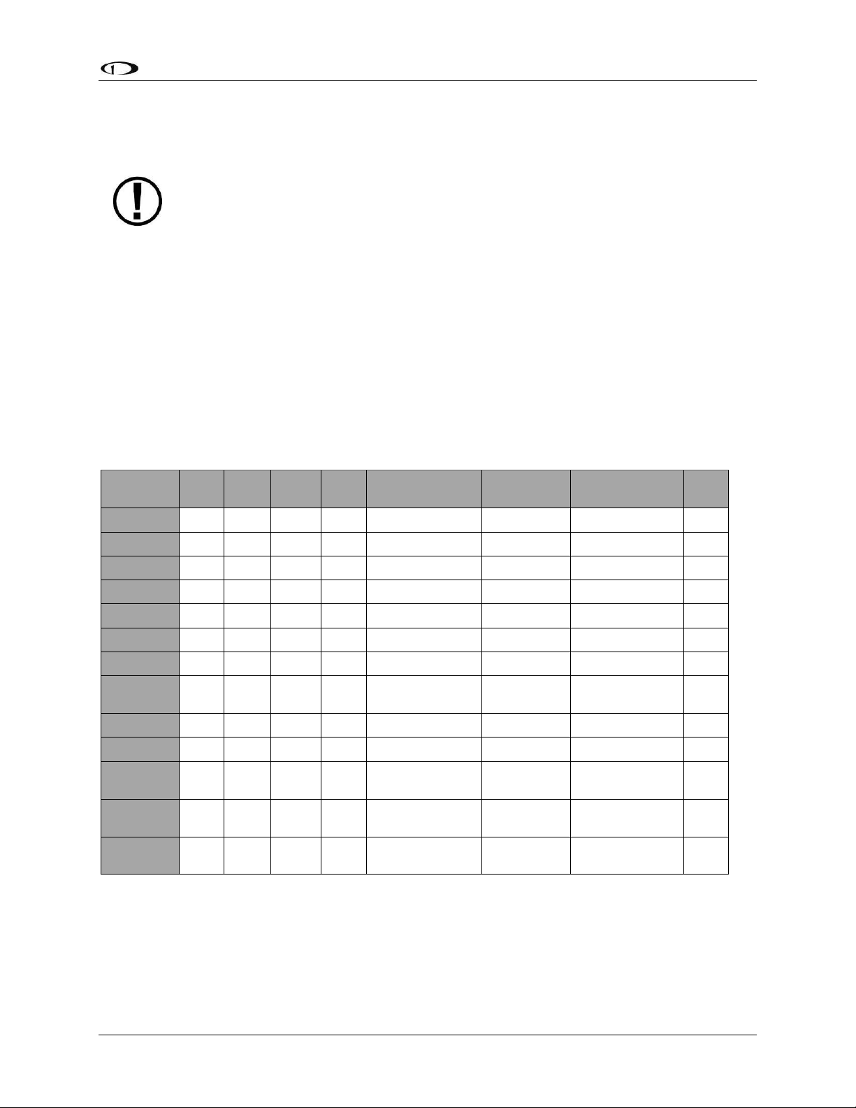
Table 2 describes which inputs and sensors are used within the ADAHRS module to generate
the different displayed instruments.
Table 2–Instruments and Sensors (*GPS only used when airspeed from pitot and static is not available)
Attitude Calculation
The SkyView artificial horizon display (attitude) is generated via a complex algorithm using a
multitude of sensors as described in Table 2. In normal operation SkyView uses airspeed to
SkyView Pilot’s User Guide - Revision S 2-3

System Overview
The SV-GPS-250’s WAAS capability does not allow it to be used as a primary
navigation source in an IFR environment where a TSO’d WAAS GPS may be
required. It does mean that it utilizes the WAAS GPS satellite to improve its
positional accuracy compared to a non-WAAS enabled GPS.
provide superior attitude accuracy. Should airspeed become unavailable due to inadvertent
pitot icing, GPS ground speed will be used as an attitude aid. You will see a GPS ASSIST
annunciation on the primary flight display when this is the case.
Compass Accuracy Effects on Synthetic Vision, Map Performance, and Autopilot
It is critical that the magnetic heading be as accurate as possible for optimal Synthetic Vision
and Moving Map performance. The ADAHRS must be installed correctly, calibrated, and
operating well in all attitudes. However, it is important to note that magnetic heading is not
used to aid attitude determination under any circumstance.
SV-EMS-22X
The engine gauges on your SkyView Engine Page are generated from the data acquired by the
SV-EMS-22X Engine Monitoring module and its sensors. This module supports popular four and
six-cylinder engine installations and can measure a variety of engine and environmental
parameters such as RPM, manifold pressure, oil temperature and pressure, exhaust gas
temperature (EGT), cylinder head temperature (CHT), fuel levels for multiple tanks, voltage,
current, fuel pressure, fuel flow, carburetor air temperature, coolant pressure and
temperature, flap and trim potentiometers, external contacts, and general purpose
temperature sensors. Two SV-EMS-22X modules can be installed to monitor either extra
CHT/EGTs for large engines or dual engines.
SV-GPS-250
The SV-GPS-250 GPS Receiver module is an optional externally mounted 5 Hz WAAS enabled
GPS receiver designed specifically for use with SkyView. It supplies GPS data in NMEA format
and automatically sets the time on SkyView.
SV-BAT-320 Backup Battery
The SV-BAT-320 Backup Battery is an optional backup battery for use with SkyView. It can
power a typical SkyView display and most of its connected modules for at least 60 minutes in
the event of failure of the aircraft electrical system.
Autopilot Servos
SV32, SV42, and SV52 servos enable SkyView to operate as an autopilot.
2-4 SkyView Pilot’s User Guide - Revision S

System Overview
Navigation Mapping Software (SV-MAP-270)
SkyView has a robust navigation mapping option that is enabled by a one-time licensing of your
SkyView system. Aviation and Obstacle data is available for free for US-based customers, and is
available via Jeppesen and PocketFMS for other customer worldwide. Additionally, when this
option is equipped, SkyView can display VFR and IFR en-route charts, procedure charts (plates),
and airport diagrams through subscriptions from either Seattle Avionics or PocketFMS. See the
SV-MAP-270 Navigation Mapping Software section of this guide for further details about
SkyView’s mapping capability.
SV-XPNDR-26X
The SV-XPNDR-261 and SV-XPNDR-262 are TSO’d remote mounted Mode-S transponder
modules that, in addition to their transponder capability, contain ADS-B Out capability via 1090
ES, and TIS traffic input capability (US Only).
SV-ADSB-470
The SV-ADSB-470 is a UAT Band (978 MHz) ADS-B receiver. It can receive traffic and weather
information from the ADS-B system that is currently being deployed by the FAA in the US,
allowing it to be displayed on your SkyView system.
VIDEO INPUT ADAPTER
SkyView video input adapter plugs into a SkyView USB port and allows you to display any SVideo or Composite video source on your SkyView Display in full screen or half screen modes.
SV-COM-C25
The SV-COM-C25 is an integrated VHF Com Radio for SkyView consisting of two modules, the
SV-COM-PANEL, and the SV-COM-425. The SV-COM-C25 has 25 kHz spacing and is able to tune
frequencies by integrating with SkyView’s aviation database. SkyView can support two SkyView
COM radios. The SV-COM-C25 is available in both horizontal and vertical versions.
SV-COM-X83
The SV-COM-X83 is an integrated VHF Com Radio for SkyView consisting of two modules, the
SV-COM-PANEL, and the SV-COM-T8. The SV-COM-X83 has 8.33 kHz spacing and is able to tune
frequencies by integrating with SkyView’s aviation database. SkyView can support two SkyView
COM radios. The SV-COM-X83 is available in both horizontal and vertical versions.
SkyView Pilot’s User Guide - Revision S 2-5

System Overview
SV-INTERCOM-2S
A two-place stereo intercom that is designed to pair perfectly with your SkyView System and
SkyView COM Radio. It has stereo inputs for SkyView, stereo music, and multiple other mono
muting and non-muting inputs for all the technology in your cockpit.
SV-KNOB-PANEL
The SV-KNOB-PANEL is an optional panel-mounted module for SkyView. This control panel has
three knobs dedicated to the most common SkyView bug functions. This module is particularly
useful in systems with the SkyView autopilot installed. The SV-KNOB-PANEL is available in both
horizontal and vertical versions.
SV-AP-PANEL
The SV-AP-PANEL is an optional panel-mounted module that affords dedicated controls for the
SkyView Autopilot. The SV-AP-PANEL includes dedicated buttons for engaging the Autopilot,
Flight Director, and all modes including setting up fully-coupled approaches, VNAV, IAS Hold,
and mode sequencing. It also has a LEVEL button to immediately return the aircraft to straight
and level flight. The SV-AP-PANEL is available in both horizontal and vertical versions.
2-6 SkyView Pilot’s User Guide - Revision S

The SkyView SV-D700 and SV-D1000 displays are identical in functionality and
presentation. The only difference is in the size and resolution of the screen. SVD1000T displays also include all the same functionality found in the other displays.
3. SV-D700, SV-D1000 and SV-D1000T Operation
After reading this chapter, you should be familiar with basic SkyView display operation. For
details regarding specific procedures (e.g., adjusting the barometer), refer to the PFD, EMS, and
Moving Map operation chapters.
Screen Synchronization
If you have multiple SkyView displays in your aircraft, the system will synchronize important
information between them. Actions such as setting baro, bugs, engaging the autopilot, or
acknowledging warnings only need to be performed on one display (or control panel) to be
reflected across the system.
Some settings such as screen layout and map range level are not synchronized on purpose.
Firmware sensor configuration file (.sfg) updates must also be done to each screen individually.
Navigation and obstacle databases may or may not synchronize, depending on whether the
displays are connected together via Ethernet. Reference the SkyView System Installation Guide
for more information on this topic.
If you are using two EMS modules to monitor dual engines, the engine page layouts and enginespecific timers like the Hobbs and Tach time, as well as engine alerts, are not synchronized
between multiple displays. Additionally, fuel computer computations may or may not be
combined between displays depending on system configuration. See the SkyView System
Installation Guide for additional details on this topic.
Display Bezel Layout
Figure 1 illustrates the front of an SV-D1000 display and its important parts.
SkyView Pilot’s User Guide - Revision S 3-1
SV-D700, SV-D1000 and SV-D1000T Operation
The set of button labels displayed immediately after the display turns on is referred
to as the Main Menu.
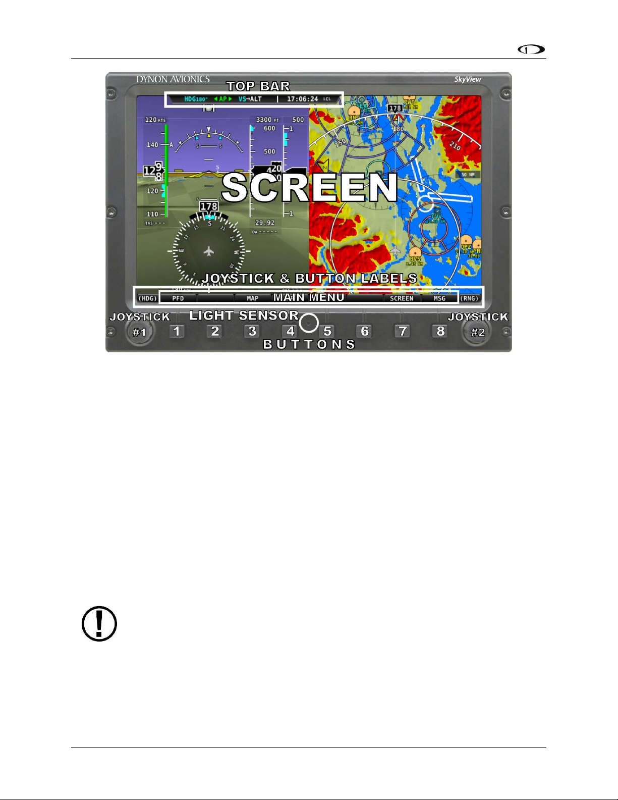
Figure 1–SkyView Display Front Bezel Layout
Note the Top Bar, screen, joystick and button labels, light sensor, two joysticks and eight
buttons.
The Top Bar is user configurable and displays important textual information. The Top Bar will
display clock time or a timer (when running), autopilot status, battery status (when an issue
requiring attention is detected), transponder status, and COM Radio status. Reference the How
to Configure the Top Bar Section of this guide for details on how to configure the Top Bar.
The screen shows PFD, Engine, and Moving Map data, configuration information, and system
alerts. Its layout is user configurable. See the Screen Layout Configuration Section for specific
instructions on how to configure the layout of your screen.
Joystick and button labels are also on the screen as seen in Figure 1. Joystick and button
functionality is contextual based on what is onscreen and these labels show the user the current
function. For example, the (MAP) label above joystick #2 in Figure 1 shows that manipulating
that joystick will affect what the user can see on the Moving Map Page.
Each SkyView display has an integrated light-detecting sensor in the front bezel. This light
sensor can be used for automatic backlight level management. Reference the SkyView System
Installation Guide for instructions on how to configure the display for automatic backlight level
management.
3-2 SkyView Pilot’s User Guide - Revision S
SV-D700, SV-D1000 and SV-D1000T Operation
Button labels are called out in all capital letters such as BACK, EXIT, FINISH, and
CLEAR. This guide directs users to press a button by using its label. For example,
when this guide asks you to press FINISH, it is asking you to press the button with
the FINISH label above it.
Joystick and Button Operation
Joysticks and buttons are used for various functions including powering the unit on and off,
entering and navigating menus, and adjusting values.
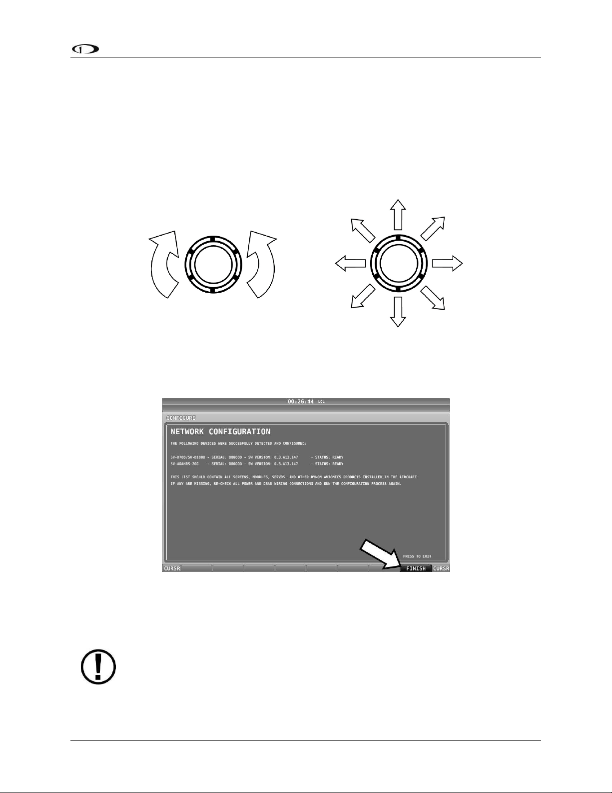
Operation Basics
Joysticks can be turned and moved. Specific joystick behavior is addressed in subsequent
sections of this guide when necessary.
Figure 2–Joystick Turn (left) and Movement (right) Directions
A button has a function if there is a label above it. If there is no label, there is no function. The
figure below shows an example button label.
Figure 3–Example Button Label
When you press the softkey button (or tap its label on SkyView Touch) momentarily, its action
is invoked.
SkyView Pilot’s User Guide - Revision S 3-3
SV-D700, SV-D1000 and SV-D1000T Operation
All menu navigation in this guide starts at the In Flight Setup Menu.
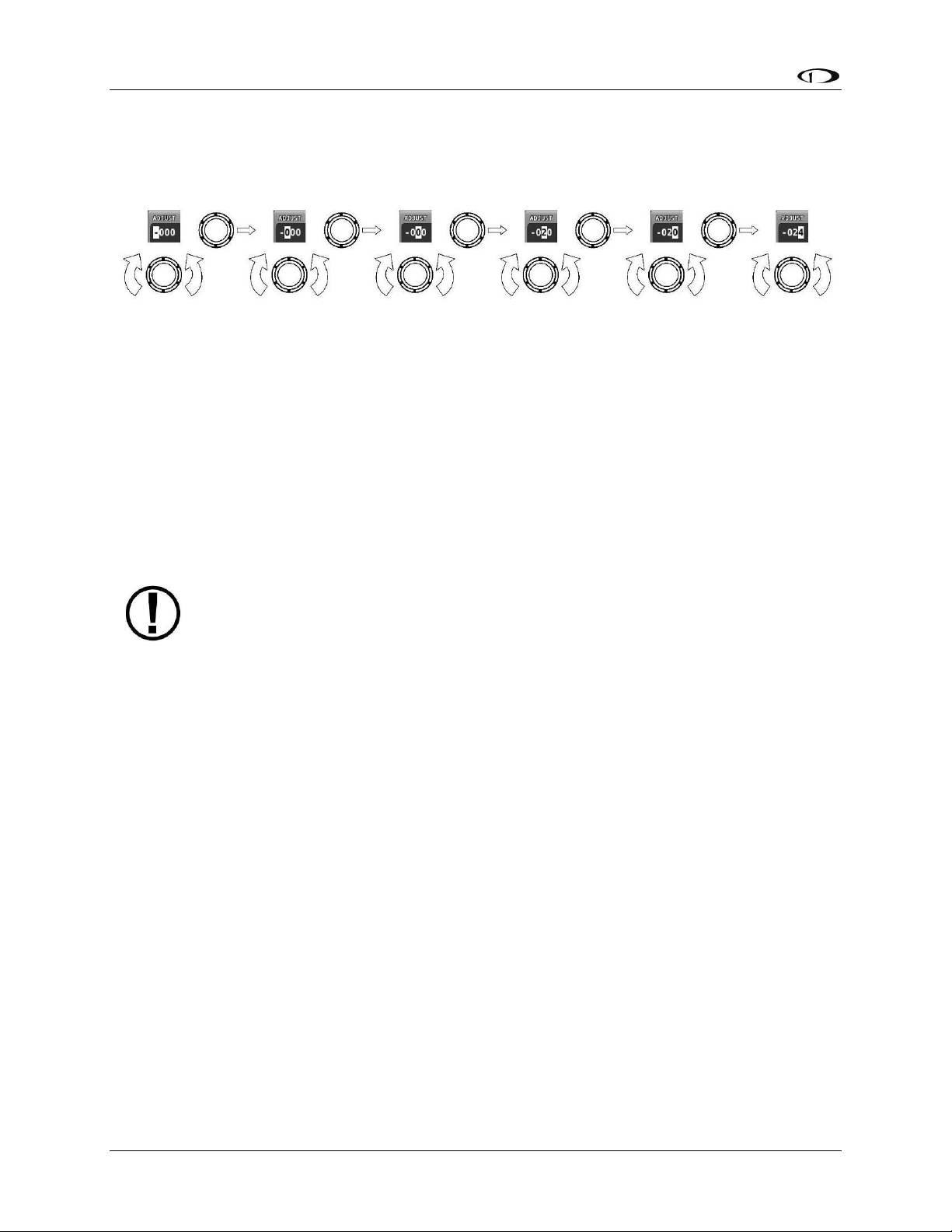
Joystick and Button Operation Example
Some parameters may need to be adjusted using a joystick. When setting values with the
joystick, each character (symbol, letter or digit) must be selected and adjusted successively.
Figure 4–Adjusting Successive Characters with a Joystick
In this example, the first time you turn the joystick, you toggle between the “-” and “+”
symbols. To change the succeeding characters, you must move the cursor joystick to the right.
In this example, you first adjust the “-” or “+” character, move the joystick right, then adjust the
one hundreds digit, and so forth. Once you have adjusted the value appropriately, press
ACCEPT or move the joystick to the right again.
At times, the next item in the menu path in this guide may be a joystick selection OR a button
push—the correct choice will be apparent.
Menu Navigation
After the display turns on, you will see a screen similar to the one in Figure 1. This guide refers
to the label bar at the bottom of the screen as the Main Menu.
Throughout this guide, the “>” character is used to indicate a sequence of menu selections or
other actions you would take as you navigate the menu system. Menu selections which are
followed by “…” indicate full-screen wizard interfaces which guide you through the appropriate
steps. These wizard interfaces are not described in detail in this guide, as the on-screen
instructions provide adequate information.
SkyView menus follow this structure: SETUP MENU > MENU > ... > MENU > PAGE or WIZARD.
The setup menus (In Flight Setup or Setup) are the root of most menu navigation. Each nested
menu is more specific than the previous one and there is no set limit for the number of nested
menus before reaching a page. A page or wizard is at the end of the chain and it is where the
user can perform a specific action such as create a system software backup, configure a
SkyView network, or set up the layout of the onscreen engine gauges. Wizards employ easy-tofollow onscreen instructions.
For example, SETUP MENU > SYSTEM SETUP > MEASUREMENT UNITS > BAROMETER indicates
entering the SETUP MENU, then selecting SYSTEM SETUP, then selecting MEASUREMENT
UNITS, and then entering the BAROMETER Menu to select INHG, MBAR, or MMHG.
Table 3 is a summary of menu navigation.
3-4 SkyView Pilot’s User Guide - Revision S

SV-D700, SV-D1000 and SV-D1000T Operation
Desired Menu Action
User Action
Enter the Setup Menu
Simultaneously press and hold buttons 7 and 8
(if airspeed is greater than zero, you will enter the
In Flight Setup Menu)
Scroll through different menus
Turn either joystick
OR
Move either joystick up or down
Enter menu
Move either joystick toward the right
Return to previous menu
Move either joystick toward the left (saves settings)
OR
Press BACK (saves settings)
OR
Press CANCEL (does not save settings)
Save adjusted value
Press ACCEPT
Reset adjustable value
Press DEFAULT
Save settings and return to Main Menu
Press EXIT
Table 3–Menu Navigation Summary
SkyView Pilot’s User Guide - Revision S 3-5

SV-D700, SV-D1000 and SV-D1000T Operation
SkyView System
Displays
Toggle SkyView System Power
One display
Toggle primary power state
OR
Toggle display power by pressing and holding button 1
Multiple displays
Toggle primary power state
OR
Toggle all displays off or on by pressing and holding
button 1 on each display.
Basic Display Operation Procedures
This subsection covers basic operation procedures for displays. Detailed instructions for various
menus and individual menu items are described in the SkyView System Installation Guide.
How to Turn the System On or Off
Table 4 summarizes the procedures for toggling SkyView system power states.
Table 4–How to Toggle SkyView System Power State
In the first seconds after turning a SkyView display on, you may see momentary display artifacts
such as multicolored lines and/or flashes of light as the display initializes. This is normal.
Loss of External Power with Backup Battery Connected
If external power is lost to a display that is connected to a backup battery, it will either stay on
for an additional 30 seconds or stay on indefinitely depending on whether or not the aircraft is
in flight. This feature minimizes backup battery discharge when on the ground and
master/external power is shut off normally. It also reduces pilot workload during an actual inflight power loss.
If the aircraft is not in flight, SkyView displays the message “POWERING DOWN IN xx SECONDS”
while counting down from 30 seconds. During this countdown, the menu displays the buttons
STAY ON and PWR OFF at the bottom of the screen. Press PWR OFF to turn off the SkyView
display immediately. Press STAY ON to keep the SkyView display on via the connected backup
battery. If STAY ON is pressed, the display will continue to use the backup battery to power
itself until the battery’s charge is depleted or the display is turned off manually pressing and
holding button 1. Finally, if neither button is pressed before the countdown expires; the display
will automatically turn off after 30 seconds to conserve the backup battery charge.
If the aircraft is in flight, SkyView displays the message “AIRCRAFT POWER LOST” with no
additional count down. This ensures that active pilot action is required to turn off a display
when power is lost in-flight and backup battery power is available. The STAY ON and PWR OFF
buttons are still offered, but the display will stay on indefinitely unless PWR OFF is pressed.
3-6 SkyView Pilot’s User Guide - Revision S

SV-D700, SV-D1000 and SV-D1000T Operation
How to Reboot the Display
Press and hold buttons 1, 2 and 5 simultaneously to instantly reboot the system. This may be
helpful if you need to cycle power after changing certain settings and for general
troubleshooting.
How to Manually Adjust the Backlight Brightness or Dim Level
SkyView’s display backlighting is controlled by its ambient light sensor to actively adjust the
brightness based on the current lighting conditions in the cockpit. The brightness is
synchronized across multiple displays and SkyView network panel mounted modules (COM
Radio, Knob Control Panel and AP Control Panel).
If however, you find that the displays are too bright or not bright enough for you, you can
adjust the brightness by pressing SCREEN on the Main Menu and then pressing DIM. This menu
allows you to manually choose an offset from the default brightness values based on current
ambient lighting. This lets you fine tune the brightness of the display to your preference, while
still allowing SkyView to adjust for changing lighting conditions.
To decrease or increase the backlight brightness press DEC- or INC+, respectively or twist the
joystick labeled DIM. The current offset appears in a window above the DIM knob. Press
DEFAULT to quickly reset the offset to zero. Press FULL to quickly set the offset to its maximum.
Press BACK twice to exit the Dim Menu and return to the Main Menu.
SkyView will not dim the display to a level that would cause it to be illegible for the ambient
lighting conditions.
On boot up, depending on your SkyView settings, the dimming offset will either be reset to zero
or remember the previous setting. See the SkyView System Installation Guide for further
information about the brightness settings.
How to Enter the Joystick Function Menu
These menus are used to specify which bug or parameter that joystick adjusts if turned. For
example, joystick 1 could be set to adjust the heading bug and joystick 2 could be set to adjust
the altitude bug.
Figure 5 illustrates the joystick menu when all possible bugs and functions are enabled. The
joystick menu on your display may contain fewer items than seen here:
SkyView Pilot’s User Guide - Revision S 3-7

SV-D700, SV-D1000 and SV-D1000T Operation
Figure 5–Joystick Menu
To set the function of a joystick:
1. Click a joystick or move it in any direction to enter its Joystick Function Menu.
2. Choose the joystick function by moving the joystick up or down.
3. Confirm the highlighted function by clicking the joystick or moving it left or right.
If the Map Page is onscreen, the joystick closest to the Moving Map is labeled (MAP) and is used
to affect the Map Page and cannot be assigned a different function.
How to Enter the In Flight Setup Menu
When airspeed is greater than zero or groundspeed is greater than 15 knots, simultaneously
pressing and holding buttons 7 and 8 when on the Main Menu will open the In Flight Setup
Menu. This menu gives users access to SkyView system tools which may be useful during flight
such as the Flight Angle Pitch Adjust Page and the Angle of Attack Calibration Wizard.
You may also access the Setup Menu from the In Flight Setup Menu by using the ENTER FULL
SCREEN SETUP MENU… option.
How to Check Installed Database Status
Enter the Installed Databases Page (IN FLIGHT SETUP MENU > FULL PAGE SETUP MENU > LOCAL
DISPLAY SETUP > INSTALLED DATABASES) to see which databases are installed and their
respective versions.
How to Adjust Time Zone Offset
Enter the Time Zone Offset Page (IN FLIGHT SETUP MENU > FULL PAGE SETUP MENU > SYSTEM
SETUP > TIME > TIME ZONE OFFSET) and adjust the time zone accordingly.
How to Configure the Top Bar
The Top Bar is the strip across the top of the screen. It displays textual information such as the
clock and autopilot status. Future software updates will use this space for information such as
radio status.
Enter the Top Bar Setup Page to configure the Top Bar (IN FLIGHT SETUP MENU > FULL PAGE
SETUP MENU or > LOCAL DISPLAY SETUP > TOP BAR SETUP).
3-8 SkyView Pilot’s User Guide - Revision S

SV-D700, SV-D1000 and SV-D1000T Operation
SkyView displays only display data from connected modules. For example, if an SVEMS-22X module is not present on the network, the display will not show any
engine data.
Page
100%
80%
60%
50%
40%
20%
OFF
PFD
Engine
Map
Video
Manufacturers that install SkyView into their aircraft can choose to standardize the
screen layouts that are available. When a SkyView system is set up this way, you
may not be able to remove some or all of the pages on a display. Additionally, the
LAYOUT and SWAP buttons may not be available.
Screen Layout Configuration
SkyView can display many combinations of PFD, Engine, and Moving Map data in full-screen
and partial-screen configurations as well as distribute this data across multiple displays. Each
display in the system can also have its own layout. This section tells you how to configure the
display(s) in your SkyView system.
The following table lists the amount of screen space you can allot for a given page. Note that
pages may also be turned off by the user.
Table 5–Onscreen Page Allotments
The following diagram illustrates example screen layout configurations.
Figure 6–Example Screen Layout Configurations
SkyView Pilot’s User Guide - Revision S 3-9

SV-D700, SV-D1000 and SV-D1000T Operation
Selecting and Arranging Pages on your SkyView Screen
1. Press SCREEN on the Main Menu.
2. Press PFD PG, EMS PG, or MAP PG to toggle the display of page on or off.
a. Alternately, press and hold any of the above buttons for a few seconds to turn
on that page and turn all others off with just one button push.
3. Press LAYOUT to toggle between different layouts of the pages that are being displayed.
4. Press BACK to finalize the layout and return to the Main Menu.
Swap Mode
You may, at times, wish to swap the entire screen contents of your left and right displays
without having to select and deselect each page on each display using the above process. This
can be useful for flying from the “other” seat, for use when flight instructing, etc.
Press SCREEN > SWAP on either display to enter swap mode and switch the screen contents of
both displays simultaneously. When your screens are in swap mode, the PFD PAGE, EMS PAGE
MAP PAGE, and LAYOUT buttons are unavailable. Press SWAP again to exit swap mode and
revert to normal display operation.
Note that the SWAP button is only shown on SkyView systems that contain exactly two displays.
Reversion Mode
In multi-display SkyView systems, you can specify a reversion mode that automatically changes
the screen configuration to a specific layout when only one display remains powered on.
For example, if you normally have your left display configured to show PFD and your right
display showing Engine and Map, reversion mode could be configured to show all three pages
automatically on the single remaining display, should the other fail.
If reversion mode is enabled, any one of the following layouts can be pre-configured (via
SkyView setup procedures) to be displayed when only one display remains powered on in a
multi-display system. This behavior applies equally whether all but one display in your system
has failed, or if you turn on one SkyView display before all others (as some customers do to see
engine instruments before engine start):
PFD 40% / EMS / MAP 40%
PFD 50% / MAP 50%
PFD 50% / EMS 50%
PFD 80% / EMS 20%
PFD 100%
See the SkyView System Installation Guide for further information about Reversion Mode
configuration.
3-10 SkyView Pilot’s User Guide - Revision S

SV-D700, SV-D1000 and SV-D1000T Operation
A battery is fully charged when it reaches 12.25 volts and should power a typical
SkyView system for at least 60 minutes. If SkyView has switched to the backup
battery due to a power loss in your aircraft, it is advised that you land as soon as
possible.
Backup Battery Charging and Testing
In the event of an electrical failure that causes SkyView to run on the SV-BAT-320, the SV-BAT320 supplies power to the SkyView display it is connected to, along with any connected SVADAHRS-26X, SV-EMS-22X, SV-ARINC-429, and SV-GPS-250 modules. Because of higher power
requirements, the SV-BAT-320 does not power Autopilot servos, the SV-XPNDR-26X, SV-COMC25, SV-COM-X83, devices connected via a serial connection, or any other third party devices.
SkyView’s maximum display brightness is reduced very slightly when operating on backup
battery power to reduce power consumption.
When connected, the battery's charge level is automatically managed by the SkyView display it
is physically connected to. This ensures that SkyView has a fully charged backup battery in case
of emergency. Charging a completely discharged battery may take up to 4 hours. To conserve
your aircraft battery, the SV‐BAT‐320 is only charged when SkyView detects that your alternator
or generator is online. Specifically:
If SkyView system voltage is above 12.25V: SkyView runs on master power and charges
the SV-BAT-320.
If SkyView system voltage is above 10V, but below 12.25V: SkyView runs on master
power but does not charge the SV-BAT-320.
If SkyView system voltage is below 10V: SkyView runs on the SV-BAT-320. This
discharges the SV-BAT-320.
Reference the SkyView System Installation Guide for more details regarding current
consumption while charging a backup battery.
Backup Battery Status
SkyView performs an automatic 30 second self-test of the battery every time a SkyView is shut
down normally when master power is turned off after a flight. Additionally, a manuallyactuated discharge test should be performed annually when prompted by SkyView.
A battery status icon in the top bar and alert messages let you know when SkyView’s backup
battery is not operating nominally. These indications are as follows:
No battery icon displayed
No battery has been connected to this display or battery status is normal. If a battery is
connected, and no icon is displayed, all of the following are true:
o The Annual Backup Battery Test is not yet due.
SkyView Pilot’s User Guide - Revision S 3-11
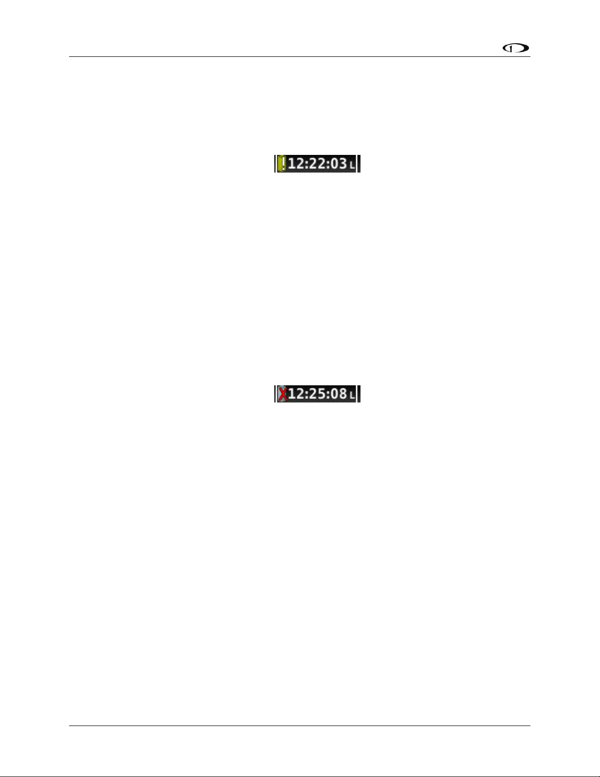
SV-D700, SV-D1000 and SV-D1000T Operation
o The self-test routine has not discovered abnormal behavior. Backup battery self-
tests are performed automatically every time master power is removed on the
ground (after a flight, for example) while the 30-second “power lost” timer is
counting down.
Needs test:
Figure 7 - Backup Battery Test Needed
SkyView has determined that the backup battery should be tested using the manually-
actuated Backup Battery Test. This can be because:
o It has been one year since the last full Backup Battery Test. See the SkyView
System Installation Guide for instructions on how to perform this test.
o The 30 second automatic battery self-check that is performed when master
power is removed during a normal shutdown did not complete properly at least
3 consecutive times. Perform the Backup Battery Test per the SkyView System
Installation Guide.
Fault/test Failed
Figure 8 - Backup Battery Test Failed
A fault has been detected because of one of the following conditions:
o The battery is no longer connected.
o A battery test has failed. The battery may need to be replaced. Contact Dynon
Technical Support for more information.
3-12 SkyView Pilot’s User Guide - Revision S

SkyView’s PFD requires data from an SV-ADAHRS-20X module. Synthetic Vision
further requires valid GPS data.
The heading/track, altitude, and vertical speed bugs are used to control the
SkyView Autopilot.
4. PFD Operation
One of the main functions of SkyView is its Primary Flight Display (PFD) with Synthetic Vision.
This chapter highlights the layout of the PFD page, its symbology, and contains instructions for
adjusting bugs.
PFD Page Layout
The PFD Page as shown in Figure 9 displays important flight information and Synthetic Vision.
Figure 9–SkyView PFD
The primary information shown on the PFD includes:
Synthetic Vision
Airspeed Indicator with Airspeed Bug and Airspeed Trend Rate
Attitude Indicator with Extreme Pitch Warning Indicators (Pitch Warning Indicators not
shown in Figure 9)
Flight Path Marker
Altimeter with Altitude Bug, Altitude Trend Rate, Barometer Setting, and Density
Altitude
Vertical Speed Indicator with Vertical Speed Bug
SkyView Pilot’s User Guide - Revision S 4-1

PFD Operation
Heading Indicator/Directional Gyro with Heading Bug
Slip/Skid Ball
Angle of Attack Indicator (not shown in Figure 9)
OAT
Wind Information (not shown in Figure 9)
The PFD in Figure 9 is a basic depiction and does not include any HSI or autopilot information.
GPS Signal Source
SkyView’s PFD contains display elements – such as Synthetic Vision, ground speed, and the HSI that depend on GPS information to work. Reference the GPS Source section in the SV-MAP-270
Navigation Mapping Software chapter of this guide for information about how SkyView utilizes
and prioritizes the available GPS sources that are used for this purpose.
PFD Symbology
Bugs
The SkyView PFD makes use of airspeed, altitude, vertical speed, minimum descent altitude,
and heading (or track) bugs. Note that the altitude, vertical speed, and heading (or track) bugs
are used for autopilot control if Autopilot servos are installed. Instructions for setting bugs are
detailed in subsequent sections of this guide.
The airspeed, altitude, and vertical speed bugs are located above their respective tapes and the
heading (or track) bug is located to the lower left of the Magnetic Heading Indicator/ Directional
Gyro.
You can toggle the display state of bugs using the following procedure. Ensure that bugs that
are used as control mechanisms for autopilot axes (i.e., HDG ALT, IAS, and VS) are available on
at least one display or knob control panel. If you have multiple displays in your aircraft, you can
toggle the bugs on each independently.
1. Press PFD while on the Main Menu.
2. Press BUGS.
3. Press HDG, ALT, IAS, VS, CRS or MDA to toggle the display state of each respective bug.
If a bug label is highlighted, it will show up on the PFD and in the joystick menu.
4. Press BACK to return to the PFD Menu.
A bug is only adjustable if it is on and it is an option in the Joystick Menu. Bugs that are turned
off are displayed as “- - - “with their respective units (e.g., “- - - FT” for an altitude bug).
When all bugs are turned on, all bugs are available in the Joystick Menu as illustrated in Figure
10.
4-2 SkyView Pilot’s User Guide - Revision S

PFD Operation
Figure 10–All Bugs On
For example, if the Minimums bug (MDA) is off, it is not an option in the Joystick Menu as
illustrated in Figure 11. The same is true for other bugs.
Figure 11–MDA Bug Off
If all bugs are off, none of them show up in the Joystick Menu as illustrated in Figure 12. Also
note how the heading bug is displayed (i.e., “- - - HDG” above the BACK label).
Figure 12–All Bugs Off
SkyView Pilot’s User Guide - Revision S 4-3

PFD Operation
Figure 13–Example Airspeed Indicator
Figure 14 – Example V speeds
Figure 15–Vne as TAS
Airspeed Indicator
The Airspeed Indicator is displayed on the left side of the
PFD and incorporates an airspeed tape with a digital
readout, true airspeed (TAS), airspeed trend indicator,
and airspeed bug. Figure 13 is an example SkyView
Airspeed Indicator.
Units can be set to miles per hour, nautical miles per hour
(knots), or kilometers per hour. Reference the SkyView
System Installation Guide for instructions on how to
change the displayed units.
The airspeed tape displays indicated airspeed including
gray, white, green, yellow, and red ranges
to provide a graphical representation of
aircraft speed in relation to the aircraft's
limits. These ranges are controlled by
setting the airspeed limitations for the
aircraft. Performance speeds (Vx, Vy and
Va) are displayed as a letter on the right
side of the airspeed tape. Refer to the SkyView System Installation Guide for
instructions on how to configure the airspeed limitation color thresholds.
Airspeed will display “---” at zero through 20 knots, at which point it will become alive. Once
alive, it will read down to 15 knots. Below 15 knots, “---” will again be displayed.
The indicated airspeed (IAS) digits scroll up and down, simulating an analog Airspeed Indicator.
The rate of change of the digits provides a sense of the increase or decrease in speed.
The airspeed trend indicator (ATI) is displayed as a magenta bar on the airspeed tape. It grows
proportionally in the direction of the rate of change (acceleration or deceleration). The ATI is
scaled to indicate a 6-second airspeed trend which means that if the
acceleration is kept constant, the airspeed will end up at the number
indicated at the end of the trend line after 6 seconds have passed.
True airspeed (TAS) is digitally displayed at the bottom of the airspeed tape. If
configured with a GPS, Ground Speed (GS) is also displayed under the True
Airspeed.
In some aircraft, Vne (red line) is limited by TAS instead of IAS. When SkyView
is configured to indicate Vne as TAS, the red airspeed range will dynamically
adjust so that the TAS limit is what starts the red airspeed range. Additionally,
a red marker is shown at the IAS that Vne would be at when at sea-level on a
standard day, which is when TAS equals IAS. This lets you quickly see the
difference between your current Vne as TAS and Vne as IAS. In the example
4-4 SkyView Pilot’s User Guide - Revision S

PFD Operation
shown here, the Vne is configured to be based on a TAS of 190. However, because the aircraft is
at altitude, that TAS occurs at a lower IAS. In this case, you can see that the red range has been
lowered to an IAS of 173, which is where the TAS has reached its limit of 190.
Airspeed Bug
The airspeed bug is displayed in cyan on the airspeed tape and its associated digital readout is
displayed at the top of the Airspeed Indicator.
To set the airspeed bug:
1. Enter the Joystick Function Menu.
2. Move the joystick up or down to highlight (IAS).
3. Click the joystick or move it left or right to close the menu (this is optional).
(IAS) will now display just above that joystick. The airspeed bug setting on the PFD will be
outlined to signal that it is selected. Turn the joystick to adjust the airspeed bug. Note that
while the airspeed bug is changing, its display window lights up in cyan to draw your attention
to it. You may also synchronize the bug to current airspeed by pressing and holding the joystick
to the left or right for 2 seconds or middle (½ second click). After the bug is synchronized an “IAS
SYNC” message will appear above the knob.
Attitude Indicator
Attitude indicator symbology is displayed on PFD and incorporates a roll scale with roll pointers
and a zero pointer reference, pitch scale with horizon lines, and water line symbology. Figure 16
is an example SkyView attitude indicator.
Figure 16–Example Attitude Indicator
The roll scale contains tick marks at 10, 20, 30, and 60 degrees and larger white triangles at 0
and 45 degrees. The roll pointer (small yellow triangle on the bottom side of the roll scale)
SkyView Pilot’s User Guide - Revision S 4-5

PFD Operation
Figure 17–
Example Flight
Path Marker
points to your current bank angle. The roll scale will rotate 360 degrees. When the aircraft is
wings level, the roll pointer aligns with the roll scale zero point. The water line symbology also
indicates wings level flight.
The pitch scale has tick marks in 2.5 degree increments and every 10 degree tick mark provides
a horizon line across the width of the screen. If the displayed pitch on the screen requires
adjustment to match the view outside, use the Flight Angle Pitch Adjust Page in the In Flight
Setup Menu (IN FLIGHT SETUP MENU > FLIGHT ANGLE PITCH ADJUST…). The pitch may be
adjusted to a maximum of ±20 degrees.
The extended zero pitch line features heading markers every 30 degrees to help maintain
directional awareness when attention is being paid to the attitude indicator.
Attitude Rate Limit
SkyView’s ADAHRS will operate normally at rotational rates of up to 150 degrees per second in
any axis. If the aircraft’s rotational rate exceeds 150 degrees per second – as can happen in a
well-developed spin or when performing aggressive aerobatic maneuvers – the PFD page will
annunciate “ATTITUDE RECOVERING”. During this time, SkyView’s attitude indication may be
degraded and other instruments should be used to maintain safe flight.
After straight and level flight is restored for a few seconds, the ATTITUDE RECOVERING message
will disappear. Full performance of the attitude indication is restored. This requires no
additional action by the pilot.
GPS Assist
In the event of airspeed loss (due to icing or other blockage) an accurate attitude is maintained
if there is an accurate GPS ground speed source. When in this mode, a magenta GPS ASSIST
message is displayed on the PFD and the ground speed is displayed below the indicated
airspeed (IAS). If the connectivity with the GPS fails while in GPS assist mode, the attitude
continues to be displayed, using the last known GPS ground speed as a reference. This mode is
flagged on the horizon with a yellow CROSS CHECK ATTITUDE message. In the very rare case
that this sequence of events occurs, the ADAHRS’ attitude accuracy is reduced; use other
references in the aircraft to cross-check against the SkyView display.
Note that due to a limitation of the SV-GPS-250 hardware, it cannot be used for GPS Assist
above 415 knots ground speed if it is being used as the GPS source
Flight Path Marker
The flight path marker as shown in Figure 17 is an icon that is superimposed on
the PFD. It depicts the actual trajectory that the aircraft is flying through space. In
contrast, the attitude indicator displays the direction that the aircraft is pointed.
The flight path marker is extremely helpful in correlating and distinguishing
between aircraft attitude and flight path, giving the pilot a better understanding
of what the aircraft is doing. Given this, the marker can also be a valuable aide
for avoiding terrain when used with Synthetic Vision.
4-6 SkyView Pilot’s User Guide - Revision S

PFD Operation
The flight path marker can be enabled or disabled through the setup menus. See the SkyView
System Installation Guide for information about this setting. In order to calculate and display
the Flight Path Marker, SkyView requires an indicated Airspeed that is not zero or a GPS ground
speed of more than 25 kts. The flight path marker also uses vertical speed, magnetic heading,
GPS ground speed and ground track to calculate its guidance.
Several examples of Flight Path Marker behavior:
If the aircraft’s nose is pitched up, but the marker stays on the horizon, this indicates
that the aircraft is not climbing or descending. You will see this behavior during slow
flight.
If the aircraft is neither climbing nor descending, the flight path marker will align with
the zero pitch line. Many aircraft do not cruise at an exactly level attitude. In this case, it
is normal to have a slightly pitched up or pitched down attitude indication, even though
the flight path marker indicates the aircraft is indicating no vertical trajectory.
If the marker is to the left or right of the attitude indicator’s aircraft symbol, this
indicates that the path over the ground is different than the direction the aircraft is
pointing. This depicts the effects of wind or a slip attitude.
If the aircraft is climbing out of a canyon and the marker is above the terrain ahead, this
indicates that the aircraft, at its current trajectory, will clear that terrain.
If the aircraft is climbing out of a canyon and the marker is overlaid on the terrain
ahead, this indicates that the aircraft, at its current trajectory, will impact the terrain.
If the marker is pointed at a runway threshold during an approach, that is where you will
be when you land if you keep the same approach path to the runway.
SkyView Pilot’s User Guide - Revision S 4-7

PFD Operation
Figure 18–Example Altimeter
Altimeter
The altimeter is displayed on the right side of the PFD. It
incorporates an altitude tape and digital readout, Density
Altitude (DA), barometer setting, and altitude bug. Figure
18 is an example SkyView altimeter.
The altitude tape displays 200 units above and below the
current altitude digital readout. Each tick represents 25
units, with every 50 unit tick drawn slightly longer to
differentiate them. Units can be set to feet or meters.
Reference the SkyView System Installation Guide
instructions on how to change the displayed units.
The digital readout scrolls up and down in the manner of
an analog altimeter. The rate of change of the digits
provides a sense of the increase or decrease in altitude.
An altitude trend indicator based on current vertical
speed is represented as a magenta bar on the altimeter.
It grows proportionally as your climb or descent rate
increases/decreases. The altitude trend indictor is scaled to indicate a 6-second altitude trend.
This means that if current rate of altitude change is kept constant, the altitude will end up at
the number indicated at the end of the trend line after 6 seconds have passed.
DA will display “----” if an OAT probe is not connected to the SkyView ADAHRS module. Since
relative humidity is not readily available to SkyView in flight, density altitude is calculated using
an approximation. The results of SkyView’s DA computation will closely match a traditional
handheld E6B.
Barometer Setting
To change the barometer setting:
1. Enter the Joystick Function Menu.
2. Move the joystick up or down to highlight (BARO).
3. Click the joystick or move it left or right to close the menu (this is optional).
(BARO) will now display just above that joystick. The barometer setting on the PFD will be
outlined to signal that it is selected. Turn the joystick to adjust the barometer setting. Note that
while the barometer setting is changing, its display window lights up in cyan to draw your
attention to it.
To quickly sync the barometer, press and hold the joystick to the left or right for 2 seconds or
middle (½ second click). When BARO is synchronized a message will appear above the knob. If
none of the conditions below are met the altimeter will not synchronize and “NO SYNC” will
appear in the altimeter box on the PFD. The table below details how the BARO setting is
synchronized:
4-8 SkyView Pilot’s User Guide - Revision S

PFD Operation
With ADS-B Installed
Without ADS-B Installed
On the Ground:
Adjusts the altimeter based on the current GPS Altitude. After the
(BARO) is synchronized a GPSALT message will appear in the altimeter
box on the PFD.
In the Air:
Adjusts the altimeter based on the
METAR of the flight plan's
destination airport if within 20nm.
If there is no flight plan waypoint or
it is too far away then the altimeter
is set to the nearest ADS-B METAR
within 100nm with a valid altimeter
setting. After the (BARO) is
synchronized a SYNC message will
appear in a window above the knob
and the airport identifier will
appear in the altimeter box on the
PFD.
Adjusts the altimeter to the
standard pressure setting (i.e.,
29.92 in Hg, 1013 mbar, or 760
mm Hg).
Above 18,000 ft
indicated
altitude
Resets the altimeter to standard pressure altitude for use in the flight
levels (i.e., 29.92 in Hg, 1013 mbar, or 760 mm Hg).
Altitude Bug
The altitude bug is displayed in cyan on the altitude tape and its associated digital readout is
displayed at the top of the altimeter. The altitude bug is used as a target for the pitch axis of the
SkyView Autopilot when a pitch axis servo is installed.
The reaction of the autopilot to an altitude bug change depends on the state of the pitch axis,
its armed mode of operation, and the current state of the aircraft. See the Autopilot Operation
chapter for more information about how the autopilot uses the altitude bug.
To set the altitude bug:
1. Enter the Joystick Function Menu.
2. Move the joystick up or down to highlight (ALT).
3. Click the joystick or move it joystick left or right to close the menu (this is optional).
(ALT) will now display just above that joystick. The altitude bug setting on the PFD will be
outlined to signal that it is selected. Turn the joystick to adjust the altitude bug. Note that while
the altitude bug is changing, its display window lights up in cyan to draw your attention to it.
SkyView Pilot’s User Guide - Revision S 4-9

PFD Operation
Figure 19 - MDA Bug
Figure 20 - MDA Bug Detail
You can synchronize the altitude bug with the current altitude by pressing and holding the ALT
joystick to the left or right for 2 seconds or middle (½ second click). After the bug is synchronized
an “ALT SYNC” message will appear above the knob.
Altitude Alerter
SkyView can be configured to audibly alert as the aircraft changes altitude in relation to the
altitude bug. When the bug is active, audio out is configured, and the altitude alerter is
configured, SkyView announces “APPROACHING ALTITUDE” as the aircraft flies within a chosen
amount of feet/meters of the bug. SkyView announces “LEAVING ALTITUDE” as the aircraft flies
away from the altitude bug by more than a chosen amount of feet/meters. The altitude
thresholds that trigger the two above alerts are individually configurable, and the altitude
alerter will work whether or not the autopilot is engaged. See the SkyView System Installation
Guide for details on how to configure the altitude alerter.
Minimum Descent Altitude (MDA) Bug
The Minimum Descent Altitude (MDA) Bug allows the pilot to set a bug to alert when
approaching a set altitude. This is typically used during approaches to remain aware of
approach minimums. This bug is distinct from the altitude bug, which is used to control the
autopilot.
When the MDA bug is set:
When the aircraft descends through 200 feet above the MDA bug:
o An “APPROACHING MINIMUMS” audio alert is played.
When the aircraft descends through the MDA bug:
o A “MINIMUMS” audio alert is played.
o A visual “MINIMUMS” alert is displayed on the PFD as seen below.
4-10 SkyView Pilot’s User Guide - Revision S

PFD Operation
Figure 21 – Example Vertical Speed Indicator.
Partial Screen PFD Version on Right.
Vertical Speed Indicator
The vertical speed indicator
(VSI) is displayed to the
immediate right of the
altimeter and incorporates a
vertical speed tape, vertical
speed pointer (with digital
readout), and bug. Figure 21
is an example SkyView VSI.
The VSI tape can display
±1000 units, ±2000 units, or
±4000 units. Units can be set
to feet or meters. Reference
the SkyView System
Installation Guide for
instructions on how to
change the displayed units
and the indicator scale.
The vertical speed pointer scrolls up and
down the VSI tape, simultaneously
displaying the instantaneous vertical speed in both analog and digital formats. If there is very
little or no vertical speed, the pointer appears blank. When the PFD is configured as a 40%
page, the digital vertical speed readout appears above or below the VSI tape as shown in Figure
21, but the analog sliding behavior of the pointer is the same as described above. When the
Vertical Speed Required to Destination info item is active on the Map a magenta line is drawn
on the VSI at that speed.
Figure 22 - Vertical Speed Required to Destination
Vertical Speed Bug
The vertical speed bug is displayed in cyan on the right side of the VSI tape and its associated
digital readout is displayed at the top of the VSI. This bug is also used as a target for the pitch
axis of the SkyView Autopilot. See the Autopilot Operation chapter for details.
To set the VS bug:
SkyView Pilot’s User Guide - Revision S 4-11

PFD Operation
Figure 23–Example Magnetic Heading Indicator/Directional Gyro
1. Enter the Joystick Function Menu.
2. Move the joystick up or down to highlight (VS).
3. Click the joystick or move it left or right to close the menu (this is optional).
(VS) will now display just above that joystick. The vertical speed bug setting on the PFD will be
outlined to signal that it is selected. Turn the joystick to adjust the vertical speed bug. Note that
while the vertical speed bug is changing, its display window lights up in cyan to draw your
attention to it.
You can synchronize the vertical speed bug with the current vertical speed by pressing and
holding the VS joystick to the left or right for 2 seconds or middle (½ second click).
The vertical speed bug is used by the autopilot as a target vertical speed when it is climbing or
descending. Reference the Chapter for more information regarding autopilot functionality,
symbology, and operation information.
Magnetic Heading Indicator/
Directional Gyro
The Magnetic Heading Indicator/
Directional Gyro is displayed on the
lower center of the PFD and
incorporates a magnetic heading
compass rose, magnetic heading
digital display, turn rate indicator,
ground track GPS pointer, heading
bug, and heading bug digital display.
Figure 23 is an example SkyView
Magnetic Heading Indicator/
Directional Gyro.
The compass rose displays in
heading-up orientation. The cardinal
points are displayed as letters, and
30 degree increments are displayed
numerically without the trailing zero
(e.g., 330 degrees is displayed as 33). The numeric display at the top of the compass rose
indicates magnetic heading.
The turn rate indicator is displayed as a
curved magenta bar along the top, outside curve of the compass rose. The bar grows in the
direction that the aircraft is currently turning and is anchored at the arrow of the numeric
display. The minor tick marks to the immediate right and left of the numeric display arrow
represents a half-standard-rate-turn. The major tick marks to the left and right of the minor tick
marks represent a standard rate turn of 3 degrees per second.
The ground track GPS pointer is displayed as a magenta triangle on the inner edge of the
compass rose.
4-12 SkyView Pilot’s User Guide - Revision S

PFD Operation
Figure 24 - HSI Example: GPS
Figure 25 - HSI Example - Localizer
Heading/Track Bug
If your SkyView system includes an autopilot, the heading (HDG) bug is replaced by a track (TRK)
bug when the autopilot is flying in GPS ground track (TRK) mode. The bug is displayed in cyan
on the inner edge of the compass rose. The digital display of the bug is displayed to the lower
left of the compass rose.
To set the heading/track bug:
1. Enter the Joystick Function Menu.
2. Move the joystick up or down to highlight (HDG) or (TRK).
3. Click the joystick or move it left or right to close the menu (this is optional).
(HDG) or (TRK) will now display just above that joystick. The heading/track bug setting on the
PFD will be outlined to signal that it is selected. Turn the joystick to adjust the heading/track
bug. Note that while the heading/track bug is changing, its display window lights up in cyan to
draw your attention to it.
You can synchronize the heading/track bug to the current heading or track by pressing and
holding the joystick to the left or right for 2 seconds or middle (½ second click).
HSI
When a valid NAV or GPS source is connected to your SkyView system, its data can be displayed
on and around the heading indicator in a standard HSI presentation. Refer to the SkyView
System Installation Guide for details on how to connect and configure these data sources. The
following sections describe the HSI display elements.
HSI Source
There are two primary types of sources, GPS and NAV radio. Anytime a GPS is being used as an
HSI source, all of the HSI data is colored magenta. When a radio is being used as the source, its
data is in green. To the right of the heading indicator, a textual info item describes the data
source of the HSI. It can be any of GPS, NAV (VOR), BC (back course) or LOC (localizer).
Additionally, each GPS or radio source either has a custom name or is numbered – depending
SkyView Pilot’s User Guide - Revision S 4-13

PFD Operation
on how those devices are configured within SkyView - to prevent confusion in systems that
have multiple navigational devices. SkyView’s own navigation mapping capability is always
labeled “SKYVIEW”. The GPS waypoints are displayed in HSI info area for SKYVIEW and ARINC
navigators such as the GNS and GTN. To cycle through the available sources, press HSI SRC in
the PFD Menu.
Course Indicator
Figure 26 - HSI Course Indicator
The course indicator has an arrow at its end which points to the currently selected course.
When a GPS source is selected, course direction is automatically by the programmed route.
When a NAV radio source is selected, the course direction can be set either on the radio or via
the course (CRS) joystick function on SkyView, depending on the NAV radio that is connected.
The course indicator is fixed to the rotation of the heading indicator, so it is easy to see which
way you must turn to get on course. When tuned to a LOC, course should be set to the runway
heading via the joystick CRS function. Courses are remembered for each navigation source, this
is especially helpful when switching between VOR and ILS or GPS and ILS sources. You may also
synchronize the CRS to point at the station (when tuned to a VOR only) by pressing and holding
the joystick to the left or right for 2 seconds or middle (½ second click). After the course is
synchronized a “CRS SYNC” message will appear above the knob.
Note that when the Garmin SL30 is tuned to a LOC/ILS frequency, it disables its own OBS knob.
Course Deviation Indicator (CDI)
Figure 27 - HSI CDI
The CDI indicates how far to the left or right you are from the selected course. When in NAV
mode, full scale deviation indicates ten degrees of deviation from the VOR radial that has been
chosen as the course. When tuned to a localizer, full scale represents 2.5 degrees of deviation.
When following a GPS course, full scale represents 5 nautical miles of deviation. When on
course, the course indicator and the CDI make a solid line, making it easy to see when there is
little error in your aircraft's position. Unlike a CDI indicator found in basic aircraft, the CDI
4-14 SkyView Pilot’s User Guide - Revision S

PFD Operation
Figure 29 - HSI Bearing 1 Pointer
Figure 30 - Bearing 1 Pointer with Distance
Figure 31 - HSI Bearing 2 Pointer
Figure 32 – Bearing 2 Pointer with Distance
needle on an HSI rotates with the heading indicator and course indicator. By turning the aircraft
towards the CDI needle you reduce your deviation.
To/From Indicator
Figure 28 - HSI To Indication
Because an HSI rotates the course line on top of the heading indicator, the to/from indicator
always points at the physical VOR/LOC transmitter, or towards the GPS waypoint. If it is
pointing the same direction as the arrow at the end of the course line, then that is a "to"
indication. If it is pointing the opposite direction of the arrow at the end of the course line, then
that is a "from" indication.
Bearing Pointers
These arrows show you the bearing directly to a radio station or waypoint–in other words, the
track that you would need to fly to go directly to it. BRG 1 is yellow in color and is depicted with
a single arrow head when displayed on the HSI display. BRG 2 is orange in color and has a
double arrow head. There is also a textual information item for each bearing pointer that
describes its source (eg. SKYVIEW, NAV1, etc.) and the distance from that source in available.
Distance is only shown when only one bearing source is selected. Each of the bearing pointers
can be cycled between all available bearing sources by pressing BRG 1 or BRG2 in the PFD
Menu.
Note that some radios, such as the Garmin SL30, provide information about standby
frequencies that can be loaded into bearing pointer locations. These are only available for
standby VORs that are within range. They are labeled as SBY bearing pointers.
SkyView Pilot’s User Guide - Revision S 4-15

PFD Operation
Figure 38 -
Wind Vector
Figure 34 - HSI GPS Info
Figure 35 - HSI NAV Info
(LOC Example)
Figure 36 - Virtual DME
Figure 37 - OBS Mode Active
NAV radios tuned to a LOC/ILS frequency do not provide bearing information due to the nature
of the localizer radio signal.
Glideslope/VNAV Indicator
Figure 33 - HSI Glide Slope
This only appears when tuned to an ILS or a GPS with vertical navigation output. When
displaying an ILS glideslope, full deflection is 0.5 degrees.
HSI Info Items
Textual info items that provide additional data about the HSI source are displayed to the right
of the HSI display. The information available depends on the data being provided by the HSI
source. Examples of info items that may be displayed include DTW (distance to waypoint), ID
(VOR identifier), and frequency. When a NAV radio decodes the identifier for a frequency,
SkyView displays it in the HSI info area and tries to match the the identifier to the same one in
its aviation database. When it finds a match, it displays Virtual-DME (non-certified) distance in
magenta. Note that ARINC-connected devices like the 430/GTN do not decode identifiers, and
therefore SkyView cannot calculate Virtual-DME for those radios.
Wind Vector
Wind vector information is located just above the OAT display on the PFD. The
winds aloft arrow indicates the wind direction relative to your current direction of
flight. The wind strength, direction, and cross wind component are also textually
provided. If SkyView cannot make an accurate winds aloft calculation, the
arrow is not displayed and the numbers are replaced by dashes. The display of
winds aloft requires an active GPS connection and an OAT probe. In very light
winds, the wind speed number is not displayed, although the arrow is. Note
that due to a limitation in the SV-GPS-250 hardware, winds information will not be available
above 415 knots ground speed if it is being used as the GPS source.
4-16 SkyView Pilot’s User Guide - Revision S
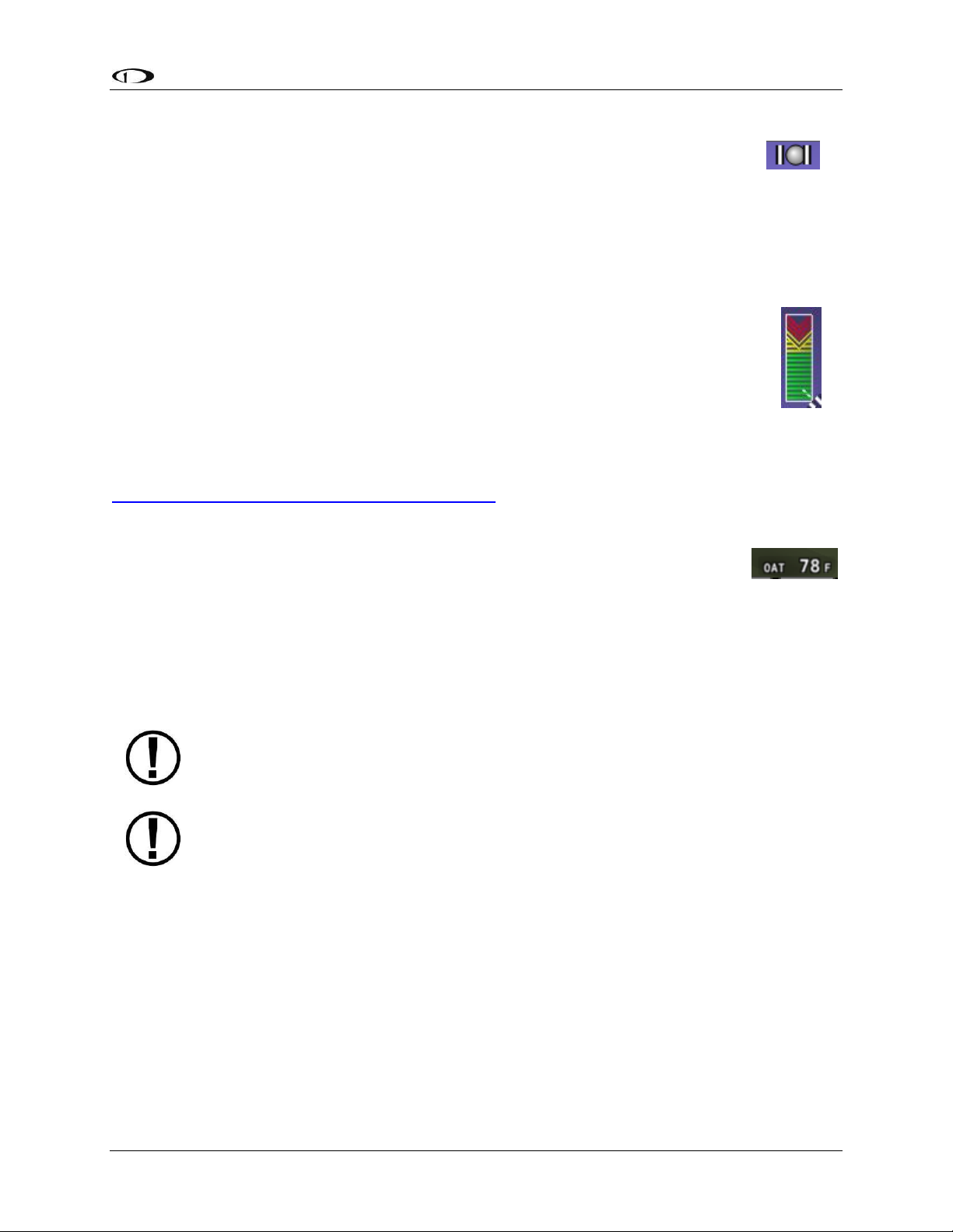
PFD Operation
Synthetic Vision depictions of terrain, runways, obstacles, and other information
are meant as informational aids only. These depictions should not be used as the
primary means for obtaining situational awareness of these features in flight.
Terrain data is obtained from third party sources. Dynon cannot independently
verify the accuracy of terrain data at all geographical points.
Figure 39–
Example
Slip/Skid Ball
Figure 40–
Example AOA
Indicator
Figure 41–
Example OAT
Slip/Skid Ball
The action of the slip/skid ball simulates an analog slip/skid ball and provides a
visual representation of lateral acceleration. When the ball is within the two
vertical lines, the aircraft is in coordinated flight. Figure 39 is an example
SkyView slip/skid ball.
Angle of Attack Indicator
The Angle Of Attack (AOA) Indicator will display only when a Dynon AOA/Pitot probe
has been properly installed and calibrated. During normal flight, the AOA Indicator
will display green. As the AOA approaches and then reaches critical, the green and
yellow bars will disappear, leaving only red. Figure 40 is an example SkyView AOA
indicator.
A thorough explanation of AOA and the principles of operation of Dynon's AOA
Pitot probe are beyond the scope of this guide. Detailed information about AOA
and Dynon's approach to AOA is available at
www.dynonavionics.com/docs/SkyView_AoA.html.
OAT
Outside air temperature (OAT) as shown in Figure 41 is displayed in the very
lower-right corner of the PFD. Units can be set to degrees Fahrenheit or degrees
Celsius. Reference the SkyView System Installation Guide for instructions on
how to change the displayed units. If OAT is not valid (i.e., disconnected or
damaged), then "OAT ---" is displayed.
Synthetic Vision (SYNVIS)
When valid GPS data is available and Synthetic Vision is licensed on a SkyView display, the PFD
features integrated Synthetic Vision. Synthetic Vision displays the terrain directly ahead of the
aircraft. Terrain is graphically represented in sectional chart color variations which represent
topographical elevations and water features. Terrain is textured with a subtle checkerboard
pattern to aid in identifying aircraft movement.
You may toggle the Synthetic Vision system off or on at any time. Press PFD on the Main Menu,
then press MODE and then press SYNVIS. Additionally, SkyView offers the ability to show
synthetic vision in “wide” mode that shows more of the peripheral view. Similar to wide angle
SkyView Pilot’s User Guide - Revision S 4-17

PFD Operation
lens camera in order to show more of the peripheral view, objects will also appear farther
away. To adjust the view Press PFD on the Main Menu, then press MODE and then press WIDE.
The following are examples of SkyView Synthetic Vision.
Figure 42 – SkyView Synthetic Vision View with Runways
Figure 43 - SkyView Synthetic Vision Normal View
4-18 SkyView Pilot’s User Guide - Revision S

PFD Operation
Figure 44 - SkyView Synthetic Vision Wide View
Runways on Synthetic Vision
Runways are depicted at airports for which runway information is available in the US only. See
the Moving Map Operation section for more information about aviation data availability. Note
that in many cases, the information in the Synthetic Vision depictions of runways may not
match the actual physical markings seen in real life. In fact, in many cases, the Synthetic Vision
depictions show more information about them. The following information is shown on
Synthetic Vision runways:
Runway edge lines
Runway centerline
Runway numbers
Runway thresholds / displaced thresholds
Aiming point markings: two white strips drawn 1000’ after the threshold on runways
4000’ and longer
Runway width threshold markings: drawn immediately after the runway threshold,
these groups of parallel lines visually indicate the width of the runway in the following
manner according to runway width:
o 0’-59’ wide: no lines
o 60’-74’ wide: 4 lines
o 75’-99’ wide: 6 lines
o 100’-149’ wide: 8 lines
o 150’-199’: 10 lines
o 200’+: 12 lines
Obstacles on Synthetic Vision
Obstacles are only depicted when the Navigation Mapping Software is licensed or in its 30 flight
hour free introductory trial mode. See the SV-MAP-270 Navigation Mapping Software section
for more information about map licensing and obtaining obstacle data.
Obstacles are only shown on Synthetic Vision if their highest point is within 1000 feet below
your aircraft’s GPS altitude. If the highest point of an obstacle is within 100 feet below your
SkyView Pilot’s User Guide - Revision S 4-19

PFD Operation
Traffic information is informational only, and does not relieve the pilot-in-command
of his or her responsibility to see and avoid traffic.
The graphical depiction of traffic is only displayed when Synthetic Vision is turned
on via the PFD>SYNVIS menu option. However, the yellow textual “TRAFFIC” alert
message on the PFD page is always shown when Traffic Advisories are known and
traffic is enabled.
current GPS altitude to anywhere above you, it will be red. If the highest point of the obstacle is
between 100 and 1000 feet below your current GPS altitude, the obstacle will be yellow. This is
the same color scheme used on the Map Page as described in the Topography with Terrain
Proximity Alerts Section.
Obstacles are shown at their actual height above the ground. In other words, if the flight path
marker is above the top of an obstacle in the Synthetic Vision version, your aircraft should clear
it in real life as well.
The tower symbology used to denote different types of obstacles is the same as used in the
Moving Map depiction. See the Moving Map Symbology section of this guide for more
information.
Traffic on Synthetic Vision
When a device that can receive traffic information is installed and configured, traffic can be
displayed within the Synthetic Vision display to improve situational awareness.
Figure 45 - Traffic Display on Synthetic Vision
4-20 SkyView Pilot’s User Guide - Revision S

PFD Operation
Traffic is displayed as reported by the device sending it to SkyView. The precision
and accuracy of the location of traffic targets may vary from device to device, and
this may impact how accurately the position is represented on the SkyView display.
For example: TIS traffic updates, such as those received by the SV-XPNDR-26X, may
be anywhere from 2-12 seconds old due to radar latency and other technical
factors. Be sure to understand the traffic-detection capabilities of your traffic
device thoroughly so you understand how to best interpret the position of the
traffic displayed on SkyView.
Traffic displayed on the PFD page can be configured to include just Traffic
Advisories (TA), all targets, or no targets. See the SkyView System Installation Guide
for information on how to configure how traffic is displayed.
Figure 46 - Traffic Advisory on
Synthetic Vision
Figure 47 - Proximity Advisory on
Synthetic Vision
Figure 48 - Non Threat on Synthetic
Vision
Traffic targets are displayed using the same symbols that are used on the Map Page display of
traffic. See the traffic section in the SV-MAP-270 Navigation Mapping Software section for
complete descriptions of the types of targets that may be shown. Unlike the Map Page display,
however, relative altitude is not provided numerically on Synthetic Vision. Instead, relative
altitude is depicted by having the traffic symbols appear either above or below the zero pitch
line, just like they would be if you were looking at traffic out the window. For example, in the
figure above, all of the traffic targets being displayed are above our current altitude. Similarly,
traffic targets that are shown to the left or right of the center of the attitude indicator are not
directly ahead of you.
Note that traffic is not visually scaled for distance. In other words, targets always appear the
same size on the Synthetic Vision depiction, no matter how far away they are. However, yellow
Traffic Advisory Targets (threats) are displayed larger than the diamond shaped Proximity
Advisory Targets and Non-Threat Targets to accentuate their increased importance.
Additionally, yellow Traffic Advisory targets contain a number within them that represents how
far away they are (in miles, nautical miles, or kilometers, depending on your system setup) from
your aircraft. The yellow Traffic Advisory target in Figure 49, for example, is 3 miles away, to the
left, above, and descending.
Figure 49 - Traffic Alert
SkyView Pilot’s User Guide - Revision S 4-21

PFD Operation
When a Traffic Advisory target is present, a yellow Traffic Alert Message appears on the PFD
Page near the top of the IAS tape. Note that Traffic Advisory targets behind your aircraft will
generate alerts. They can be seen on the Map Page, but will not be visible on the Synthetic
Vision display as Synthetic Vision only shows the view in front of the aircraft.
Extreme Pitch Warning Indicators
The SkyView PFD shows large red arrows as pitch warning indicators in extreme attitudes (i.e.,
45 degrees or greater pitch up or down). These indicators point to the horizon and indicate
which way to maneuver to attain a level attitude. Indicators are accompanied with a small sliver
of sky or ground bordered with a white dashed horizon line, depending on the current attitude.
The pitch warning indicators can be enabled or disabled through the setup menus. See the
SkyView System Installation Guide for information about this setting. Figure 50 illustrates the
pitch up warning arrows with the slivers of ground.
Figure 50–Extreme Pitch Warning Indicator Arrows
Six-Pack Presentation
In firmware version 10.0 or later, SkyView includes the traditional six-pack analog presentation
of flight instruments as well as the EFIS tape-based display. SkyView’s “six-pack” flight
instrumentation mode lets you fly the gauges you’re used to if you’re new to glass. After flying
in the six-pack mode, try out the “EFIS” style as you get comfortable: changing the presentation
is just a few buttons away.
4-22 SkyView Pilot’s User Guide - Revision S

PFD Operation
Figure 51 - Analog PFD with Synthetic Vision
Figure 52 - Analog PFD without Synthetic Vision
SkyView Pilot’s User Guide - Revision S 4-23

PFD Operation
To turn on the six-pack, SynVis, or EFIS presentation go to the PFD Menu > MODE and select the
layers to turn on either EFIS or SIX-PACK with or without SYNVIS. All the same information is
displayed on the six-pack and EFIS tapes and the six-pack format respects all the same settings.
All of the information boxes for Density Altitude, True Airspeed, Autopilot alert banners, Flight
Director, and bugs, etc. appear just like they do for the EFIS tapes. However, EFIS tapes are
required to view the Extreme Pitch Warning Indicators. The six-pack presentation can be turned
off completely in the Setup Menu, see the SkyView System Installation Guide for details.
4-24 SkyView Pilot’s User Guide - Revision S

PFD Operation
ADAHRS (Flight Instrument) Redundancy and Cross-Checking
SkyView systems support multiple SV-ADAHRS-20X modules for redundancy and manage failure
scenarios by automatically switching to backup modules should an ADAHRS completely fail.
Additionally, in the event that multiple ADAHRS disagree, the display will annunciate this with
an on-screen alert that calls out which parameter(s) are not the same on all ADAHRS.
Parameters that are continuously cross-checked include attitude (pitch and roll), magnetic
heading, G Meter, turn coordinator (slip/skid ball), airspeed, and altitude.
Figure 53 - ADAHRS Cross-Checking Disagreement
Once SkyView has annunciated a cross-check comparison problem, press COMPARE to see both
ADAHRS side-by side. The ADAHRS that was previously displayed on the PFD is labeled
“ACTIVE”, while the one that was not previously being displayed - but which was being used as
the cross-check reference – will be labeled as “STANDBY”. Additionally, the labels “PRIMARY”
and “ALTERNATE” designate which ADAHRS is normally displayed when both are in agreement
and neither is disabled.
SkyView Pilot’s User Guide - Revision S 4-25

PFD Operation
Figure 54 - ADAHRS Cross-Check Comparison
Once you have determined which ADAHRS is incorrect, press DISABLE to tell SkyView not to use
it for the duration of the flight:
Figure 55 - ADAHRS Cross-Check Comparison (one ADAHRS disabled)
4-26 SkyView Pilot’s User Guide - Revision S

PFD Operation
Figure 56 - ADAHRS Cross-Check Comparison – six-pack
Press exit to return to normal operation. The PFD will annunciate that only a single ADAHRS is
available for use:
Figure 57 - Single ADAHRS Mode Flag
If, after you’ve entered the ADAHRS comparison screen, you do not disable an ADAHRS, a red
warning and ADAHRS CROSS CHK ERROR alert will persist in the Message Alert Area (above
button 8). To go back to the ADAHRS comparison screen to disable an ADAHRS, see the below
instructions:
ADAHRS Source Selection and Configuration
Enter the ADAHRS Source Selection Page: IN FLIGHT SETUP MENU (press/hold buttons 7/8)>
ADAHRS SOURCE SELECTION…).
If you are on the ground, this will be under SETUP MENU > PFD SETUP > ADAHRS SOURCE
SELECTION.
SkyView Pilot’s User Guide - Revision S 4-27

PFD Operation
ADAHRS Status
The ADAHRS labeled ACTIVE is the one that is being displayed on the PFD.
An ADAHRS labeled STANDBY is being used for cross-checking, but it is not being displayed on
the PFD.
PRIMARY / ALTERNATE ADAHRS Selection
The ADAHRS labeled PRIMARY is the one that will be preferentially chosen by SkyView as the
active ADAHRS.
An ADAHRS labeled ALTERNATE is one that is available to be used in the event of a failure or
problem with the primary ADAHRS. However, it normally won’t be chosen for display on the
PFD unless the primary ADAHRS has failed or has manually been disabled.
To change which ADAHRS is the PRIMARY ADAHRS, highlight an ALTERNATE ADAHRS and press
the PRIMARY button to elevate it to PRIMARY status.
To disable an ADAHRS until SkyView is next powered up, simply highlight it with the joystick and
press the DISABLE button.
To see the same comparison screen that is presented when a cross-check error occurs, press
the COMPARE button at the bottom of the display.
Press BACK to exit the ADAHRS Source Selection Page or press EXIT to return to the Main Menu.
Either of these actions will save the ADAHRS source settings.
4-28 SkyView Pilot’s User Guide - Revision S

PFD Operation
PFD Menu
The PFD Menu is accessible from the Main Menu by pressing PFD (MAIN MENU > PFD). Users
can reset the baro, toggle Synthetic Vision on or off, and configure the bearing and NAV
sources.
Back
Press BACK to return to the Main Menu.
G Meter
Press G METER to toggle the G Meter on and off. When the G Meter is displayed, it replaces the
HSI/Compass Rose, though numerical magnetic heading above the HSI area remains. The G
Meter shows an analog “needle” that indicates the instantaneous G loading of the aircraft.
Depending on how the G Meter is configured, the analog range may have yellow and/or red
caution ranges configured to visually indicate aircraft G limits are being approached.
Instantaneous G information is also shown digitally in the center of the gauge.
Figure 58 - G Meter on PFD
The smaller digital numbers above and below the larger instantaneous G number are the
maximum and minimum Gs that the aircraft has experienced since the G Meter was last reset.
Press PFD > RESET G to manually reset the G Meter. The G Meter may also be set up to
automatically reset the min/max G readings every time SkyView starts up.
The G Meter can also be configured to “pop up” automatically under certain conditions. When
configured this way, the G Meter will appear automatically when the aircraft’s instantaneous G
loads exceed thresholds that have been selected. Once the G Meter has appeared, it will
remain on the display until the instantaneous aircraft G loading falls back below those
thresholds.
See the SkyView System Installation Guide for further information about G Meter configuration.
SkyView Pilot’s User Guide - Revision S 4-29

PFD Operation
SkyView’s Navigation Mapping Software course information can be displayed on
the SkyView HSI display when it is navigating to an active waypoint. It is always the
SKYVIEW source.
As this button is used frequently for IFR flight with the Autopilot, and is duplicated
in the Autopilot menu for convenience.
MODE
Figure 59 - PFD Display Mode Selection Options
Enter the Mode menu to switch between EFIS tapes and Six-Pack primary flight instrument
presentations, buttons that are grey are turned on. You can also turn Synthetic Vision on and
off, and set SynVis to normal or wide view.
Bearing Source 1 (BRG 1)
Press this button to cycle through the available bearing sources for the first bearing needle.
HSI Source (HSI SRC)
Press this button to cycle the HSI through the different navigation data sources that are
connected to the SkyView system (e.g., GPS 0-4, NAV 1-4, or custom names that may be
configured). Other than SKYVIEW, which is sourced from SkyView’s own Navigation Mapping
Software, these are all external navigation devices such as other portable GPS units (such as the
Garmin 496), panel mounted IFR GPS systems (such as the Garmin 430), and panel-mounted
navigation radios (such as the Garmin SL30). In SkyView firmware version 10.0+, pilots can
change the displayed names of external GPS and NAV radios to custom names (e.g. GPS 1 could
become “GTN650”, for example). These names appear on the PFD HSI Info Item, and for ARINC
IFR GPSs such as the GTN and GNS series, in the Flight Plan menu as well (see Navigation
Mapping Software features for more details). Reference the SkyView System Installation Guide
for more information regarding external serial navigation device installation, configuration and
naming.
Note that using the HSI SRC button to toggle the HSI source does not affect what is displayed on
the SkyView map: It normally displays the flight plan from SkyView’s own GPS mapping
capabilities. However, note that from within the MAP Menu there exists a feature that allows
one to display flight plans from external IFR GPS devices on the map.
Bearing Source 2 (BRG 2)
Press this button to cycle through the available bearing sources for the second bearing needle.
4-30 SkyView Pilot’s User Guide - Revision S

PFD Operation
The clock is part of the Top Bar which is always displayed regardless of the screen
layout.
Figure 62 - Up Timer
Figure 63 –Down Timer
Figure 64 - Down Timer Expiring
Figure 60–Example SkyView Clock
Bugs
Enter the Bugs Menu to configure which bugs are on or off. Reference the PFD Symbology Bugs
Section for more information.
Messages (Text Varies)
The Message Alert Area is always present above the rightmost button and contains important
SkyView messages and alerts.
Top Bar
The Top Bar contains a clock, as well as status information for Autopilot, Transponder, SkyView
Backup Battery and COM Radio. Clock behavior is described here. All other Top Bar behavior is
covered in the relevant chapter of this guide.
The clock is always displayed centered at the top of the screen in all screen display modes on
the Top Bar in 24 hour/military format. Time is initially sourced from a GPS feed and is only
displayed when valid GPS data is being received or if (primary or
battery) power has been maintained continuously since valid
GPS data was received. If there has never been an initial GPS
time set or time has been lost due to loss of power,”--:--:--“ is
displayed. When valid GPS data is received again, time will be
displayed.
Reference the How to Configure the Top Bar Section of this guide for instructions on how to
configure the Top Bar.
Up/Down Timers
A configurable count up/down timer can be found by going to TOOLS > TIMER.
Figure 61 - Timer Menu
Once the TIMER menu is entered, the clock in the top bar displays TIMER information instead of
the local or UTC clock that is normally shown. Leaving the timer menu will restore the clock if a
timer is not running.
SkyView Pilot’s User Guide - Revision S 4-31

PFD Operation
To operate the timer once in the TIMER menu:
MIN and SEC knobs: Turn to set the time
BACK: Leaves the timer menu and returns you to the Main Menu
ZERO: Resets the timer to zero
LAST: Resets a DOWN timer to the last value it was set to before it was started
DOWN/UP: Toggles the timer mode. Both count-up and count down timers are
available.
o When a DOWN timer reaches zero, an audible “timer expired” message is played
(if audio output is connected), the timer flashes white for a few seconds, and a
“timer expired” alert is annunciated in the message alert area. Press button 8 to
view and acknowledge this alert. If a DOWN timer is not reset, the timer will
continue to count down negatively.
o When the UP timer is running, it will stop at 99:59 minutes.
RUN: Turns the timer on and off. RUN is highlighted when the timer is on.
SkyView Knob Control Panel Operation
The SV-KNOB-PANEL SkyView knob control panel adds three additional dedicated knobs to the
SkyView system for the most frequently adjusted bugs. One knob is dedicated to each of the
Altitude Bug (ALT), Altimeter Setting (BARO) and Heading/Track Bug (HDG/TRK) on the primary
flight display. These knobs behave exactly like the SkyView joystick knobs do when they are set
to these functions: turn them to adjust the value they control. Press and hold them to
synchronize the ALT and HDG/TRK bugs to the aircraft’s current altitude or heading/track. Press
and hold BARO set the altimeter setting to either the nearest METAR (when ADS-B is available
in-flight), to standard pressure (29.92 inHg or 1013 millibars) (when at/above 18k feet or no
ADS-B on board), or to make the altimeter match GPS altitude (when on the ground).
4-32 SkyView Pilot’s User Guide - Revision S

This chapter references the Engine Page. This page should have been configured
during SkyView installation. Reference the SkyView System Installation Guide for
more information.
The three Engine Pages (100%, 50%, and 20%) should have been configured during
installation. The appearance of the 20% and 50% Engine Pages are not scaled down
versions of the 100% Engine Page. They are unique layouts and must be laid out
individually.
5. EMS Operation
This chapter describes SkyView EMS functionality and a few of the advanced ways to use it to
monitor the health and operation of your engine.
Engine Page Layout
The Engine Page as shown in Figure 65 displays important engine parameters acquired using an
SV-EMS-220 module, its sensors, and other advanced engine monitoring features.
Figure 65–Example 50% SkyView Engine Page
Its appearance is determined using the Screen Layout Editor under the EMS Setup Menu and
should have been configured during installation. All EMS widgets that have assignable color
ranges, can include: red, yellow, green, black, blue, white, purple, cyan, and orange, for
SkyView Pilot’s User Guide - Revision S 5-1

EMS Operation
Engine warning alerts are only triggered when their respective sensors are
configured as self-clearing or latching alarms. If a sensor’s alarm is configured as
off, no alert will trigger, even if that sensor’s measurement enters a range defined
as red. Reference the SkyView System Installation Guide for more information
regarding alarm configuration.
Engine parameters only trigger alerts in the Message Notification Area and
Message Window when they enter their “red” ranges. In other words, “yellow”
caution ranges for engine parameters do not trigger alerts. Yellow caution ranges,
however, are visually annunciated via yellow highlighting on the Engine Page.
customization. For more information regarding the Screen Layout Editor, reference the SkyView
System Installation Guide.
The green markings on pitch/roll/rudder trim indications, if they exist, nominally depict the
take-off position markings as defined during calibration.
Combined CHT/EGT Gauge
The combined CHT/EGT Gauge shown in Figure 66 displays all of the engine’s CHTs and EGTs in
one compact gauge. EGTs are displayed numerically down the right side of the gauge. They are
represented graphically by the solid yellow/green/red bar graph. CHTs are displayed
numerically on the left side of the gauge. They are graphically represented by the white “tick
marks” that overlay the EGT bars. When caution or alarm points are red, this tick mark changes
colors with the numbers. This representation allows all CHTs and EGTs to be displayed in a way
that affords quick comparison of their values, whether raw data or a graphical comparison is
preferred.
Figure 66 - Combined CHT/EGT Gauge
Rotax 912 Behavior
SkyView can be configured to adjust the oil temperature and tachometer gauges for the Rotax
912 engine dynamically to reflect limitations that Rotax specifies for that engine. When this
5-2 SkyView Pilot’s User Guide - Revision S

EMS Operation
behavior is turned on (per the SkyView System Installation Guide), the tachometer and oil
temperature behave in the following ways:
Tachometer for Rotax 912:
When OIL TEMP < 120ºF, the TACHOMETER displays these ranges:
0-1400 and 4000-6000 RPM in RED
1400-1800 and 2500-4000 RPM in YELLOW
1800-2500 RPM in GREEN
When OIL TEMP > 120ºF, the TACHOMETER displays different ranges:
0-1400 and 5800-6000 RPM in RED
1400-1800 and 5500-5800 RPM in YELLOW
1800-5500 RPM in GREEN
The alarm type for the tachometer is the “self-clearing” type.
Oil Temperature Gauge for Rotax 912:
When OIL TEMP < 190ºF, the OIL TEMP gauge displays these ranges:
100-120 and 230-266ºF in YELLOW
120-190ºF in GREEN if OIL TEMP has been above 190ºF “more recently” than OIL TEMP was
below 120ºF; otherwise 120-190ºF is displayed in BLACK OUTLINED IN WHITE
190-230ºF in GREEN
266-280ºF in RED.
When OIL TEMP is > 190ºF, the OIL TEMP gauge will display different ranges:
100-120 and 230-266ºF in YELLOW
120-230ºF in GREEN
266-280ºF in RED
The alarm type for oil temperature is the “self-clearing” type.
Engine Menu
LEAN
The engine monitor provides multiple methods to assist you in setting the mixture of your
engine for various functions. The first, and most basic, is to just watch the EGT display as the
engine is richened or leaned. You can watch for the EGTs to peak and then richen or lean as
desired from that point. The engine monitor also includes a leaning function to automate this
process.
SkyView Pilot’s User Guide - Revision S 5-3

EMS Operation
To activate leaning mode, press LEAN. With this mode activated, LEAN highlights, and the label
“LEAN” is displayed underneath the EGT bars to clearly differentiate it from the normal
operating mode. This is depicted in Figure 67.
Figure 67–Entering Lean Mode
As each cylinder peaks, the cylinder numbers on the left side of the EGT bars are replaced by a
number indicating the cylinder peak sequence, followed by the difference from its peak
temperature (on combined EGT/CHT graphs pages, this information replaces the EGT
temperature itself due to space constraints). Given this information, you may set your mixture
more accurately to achieve a given EGT delta value on either the rich or lean side of peak EGT.
This is depicted in Figure 68.
Figure 68–EGTs Peaking
After the last cylinder peaks during a leaning operation the difference in fuel flow between the
first and last cylinder peaks is displayed. If the fuel flow decreases, it is shown as Lean of Peak. If
fuel flow increases, it is shown as Rich of Peak. This is depicted in Figure 69.
5-4 SkyView Pilot’s User Guide - Revision S

EMS Operation
Figure 69–Lean of Peak
To exit the Lean mode, press LEAN again; the EGT/CHT display then returns to its normal state.
For best results, lean carefully by making small adjustments and allowing some time for
temperatures to stabilize before leaning further. In addition to the EGT temperatures, you can
also watch the fuel flow rate and CHT temperatures. Carefully read and follow your engine
manufacturer’s leaning recommendations for best performance.
On some engines, when given the proper set of inputs, the EMS can also calculate lean-of-peak
or rich-of-peak operation in real time. To do this, the EMS needs access to OAT, MAP, RPM,
Altitude and fuel flow, engine horsepower setting, engine redline setting, and be used on a
normally aspirated Lycoming or Continental engines. This information is based on Lycoming and
Continental power charts and is updated in real time. The leaning information has four states:
LOP, ROP, and PK (Peak), and PK? (Peak Unknown). This information can be used to determine
when it is safe to lean the engine, and if the current operating state is near peak or not. While
this information is based on published charts, you should independently verify via manual
leaning that this data matches your install and engine. If the EMS does not have all of the
information it needs to calculate the peak state, PK? (Peak Unknown) is shown.
FUEL
The FUEL menu primarily contains controls for adjusting the fuel computer. See the dedicated
Fuel Computer section for details on fuel computer operation.
CLR TMR
Press CLR TMR to reset both the Engine Trip Timer and the Flight Trip Timer to 0 hours. See the
Timers section for more information on timer functions.
Timers
SkyView has internal tach, Hobbs, and other timers that each run at different times. EMS timers
are available for placement on the Engine Pages via the Screen Layout Editor. For more
information regarding the Screen Layout Editor, reference the SkyView System Installation
Guide.
Engine timers are displayed at 1/10 hour increments.
SkyView Pilot’s User Guide - Revision S 5-5

EMS Operation
The Fuel Remaining, Fuel Used, Fuel Efficiency, Fuel at Waypoint, and Range values
are not directly measured. These values are calculated based upon measured flow
rates and user input of fuel quantity. Do not use these values as primary indicators.
Tach Time - labeled TACH when displayed on an Engine Page - is a measure of engine time
normalized to a cruise RPM. The cruise RPM parameter must be set properly in the system
setup to generate a correct tach time
Hobbs Time - labeled HOBBS when displayed on an Engine Page - is a simple timer that runs
whenever the oil pressure is above 15 PSI or the engine is above 200 RPM. It essentially runs
when the engine does.
The Engine Run Timer - labeled RUN TIME when displayed on an Engine Page - is a Hobbs style
timer that records the time your engine has been running during your current flight. It resets
the first time the engine is started after SkyView is powered on. This allows you to view your
previous flight’s Engine Run Time any time before you start your engine before a flight.
The Engine Trip Timer - labeled TRIP RUN when displayed on an Engine Page - is a Hobbs style
timer that records the time your engine has been running. Unlike the Hobbs time, it can be
reset by pressing ENGINE > CLR TMR.
The Total Air Timer - labeled AIR TOTAL when displayed on an Engine Page - runs any time that
SkyView determines that the aircraft is in flight. SkyView uses the presence of significant
airspeed or GPS speed to decide whether the aircraft is flying. This timer can only be reset or
adjusted in the Aircraft Information menu within SkyView Setup. See the SkyView System
Installation Guide for information about using SkyView’s Setup Menu.
The Air Timer - labeled AIR TIME when displayed on an Engine Page - runs any time SkyView
determines the aircraft is in flight. SkyView uses the presence of significant airspeed or GPS
speed to decide whether the aircraft is flying. Resets as SkyView detects that the aircraft has
transition to “in the air” This time is also optionally used to calculate the Switch Fuel Tank
Reminder.
The Air Trip Timer - labeled AIR TRIP when displayed on an Engine Page -runs any time that
SkyView determines that the aircraft is in flight, just like the Total Flight Timer. Unlike the Total
Air Timer, it can be reset by pressing ENGINE > CLR TMR.
A Switch Fuel Tank Reminder can be configured to alert the pilot to switch their fuel tanks at a
set time or fuel usage interval (based on the fuel computer’s fuel calculations). When enabled,
it will periodically annunciate a “Switch Fuel Tank” alert message and audio alert. There is no
visible counter for this timer. See the SkyView System Installation Guide for details on
configuring this reminder.
Fuel Computer
By using the optional fuel flow sensor and GPS information together, SkyView can generate and
display different info items that pertain to your aircraft’s computed fuel state and performance.
5-6 SkyView Pilot’s User Guide - Revision S

EMS Operation
In Dual Engine installations SkyView’s fuel computer computations may or may not
be combined between displays, depending on the configuration. See the Dual
Engine Monitoring section below for details.
To obtain accurate data, you must reset the fuel computer every time you add fuel
to the aircraft. SkyView can assist with this through the Fuel Auto Detect setting
described in this section.
They are available for placement on the Engine Pages via the Screen Layout Editor. For more
information regarding the Screen Layout Editor, reference the SkyView System Installation
Guide.
The Fuel Remaining info item (displayed as FUEL REM) displays the current amount of fuel
computed on board, based on your input of the aircraft’s starting fuel state and the amount of
fuel that has the fuel flow sensor has seen flow through it.
The Fuel Used info item (displayed as GALS USED) displays the amount of fuel that has been
used during your flight. Note that Fuel Used resets itself when the unit detects that oil pressure
has exceeded 15 PSI for the first time after being powered on. This allows you to view the fuel
used value from your last flight before engine start.
The Time Remaining info item (displayed as TIME REM) displays how much time is estimated
remaining before the aircraft is out of fuel.
The Fuel Efficiency info item (displayed as NM/GAL) displays how efficiently the aircraft is using
fuel with respect to the speed it is traveling over the ground (this also can be displayed as
MI/GAL, KT/GAL, KM/LTR).
The Fuel at Waypoint info item (displayed as WPT GAL) displays how much fuel will remain at
the next waypoint. This info item uses the current HSI navigation source for waypoint
information, and only displays information when there is a waypoint being navigated to. It
assumes you are flying directly at the waypoint and does not adjust for non-direct flights.
The Fuel Range info item (displayed as RANGE) displays the distance the aircraft can travel at its
current GPS ground speed before it is out of fuel.
Fuel Menu (Adjusting the Fuel Computer)
Fuel computer adjustments are made under the ENGINE > FUEL menu. When FUEL is pressed,
the window in Figure 70 is displayed:
SkyView Pilot’s User Guide - Revision S 5-7

EMS Operation
Beware that the value that SkyView adjusts the fuel computer when MATCH is used
is only as accurate as your fuel level sensor measurements.
Figure 70–Fuel Computer and Fuel Menu
“Fuel Computer Quantity Adjustment” is the amount of fuel that you have told the fuel
computer to presently add or subtract from the previous total fuel state.
“Current Fuel Computer Quantity” is the total amount of fuel on board as far as the fuel
computer knows. This is the number that ultimately needs to be correct in order for the
fuel computer to accurately perform its calculations.
“Measured Fuel (In-Tank Sensors)” is the amount of fuel measured by the resistive or
capacitance senders, if installed. If these are well-calibrated, then the Total Fuel and the
Measured Fuel lines should be very close to each other.
There are a few different ways to adjust the fuel computer’s fuel state:
While the FUEL menu is displayed, turn the FUEL knob to add or subtract fuel. This is
limited to adjustments that set the Total Fuel to between 0 and the total fuel capacity as
defined in the Setup Menu.
Press FULL to have SkyView recall a previously programmed amount of fuel which
represents the full fuel load of the aircraft. See the SkyView System Installation Guide
for information about how to set this value.
Press PRESET to have SkyView recall a previously programmed amount of fuel which
represents different fuel loading besides “full”. This is commonly used in aircraft that
have visual tabs in the tanks to easily fill to a non-full but well-defined fuel state. See the
SkyView System Installation Guide for information about how to set this value.
Press MATCH to have SkyView automatically add/subtract the appropriate amount of
fuel so that Total Fuel matches the Measured Fuel value that the physical fuel tank
sensors are measuring. Press ACCEPT to confirm the new displayed Total Fuel and exits
the FUEL menu,
Press CANCEL to discard any changes made to the Total Fuel and exit the FUEL menu.
Auto Fuel Detect
The fuel computer can optionally be configured to detect when fuel has been added while
SkyView was off, as would be the case during a normal refueling operation. When configured to
detect fuel additions, SkyView will automatically display the FUEL menu upon startup as a
5-8 SkyView Pilot’s User Guide - Revision S

EMS Operation
reminder to adjust the fuel computer, along with a FUEL MISMATCH message to indicate that
the fuel measured by the in-tank fuel quantity sensors does not closely match the fuel
computer’s fuel remaining value.
Dual Engine Monitoring
For aircraft with two engines, SkyView can be configured to monitor both engines when two
SV-EMS-22X modules are installed. This requires two or more SkyView displays in the system, as
each EMS module’s information is displayed on one display exclusively. In this set up each
engine is monitored independently on a single display.
One exception to the above is that SkyView’s flow-based fuel computer feature can be
configured in one of two ways: In one configuration, it will totalize all fuel and usage
throughout the aircraft – as you’d want when there is a single combined fuel system in the
aircraft. Alternatively, it can compute each engine’s fuel totals and usage quantities separately,
as you’d want if each engine were served by a completely independent fuel system. In either
case, the instantaneous fuel flow reading will be indicative of the current fuel usage of the
corresponding engine. The following info items will either be based on either the total fuel in
the aircraft or the total fuel per fuel system: Fuel Remaining, Fuel Used, Fuel Efficiency, Fuel at
Waypoint, and Range values.
In a dual engine system, the following timers are running when either engine is running: Run
Time, Total Air Time, Trip Run, Air Trip, and Air Timer. However, the Hobbs and Tach timers are
tied to the individual engine.
See the SkyView System Installation Guide for more details on setup and configuration of dual
engine monitoring.
VP-X Operation
Dynon SkyView can interface with the Vertical Power VP-X System to provide robust monitoring
and control of your electrical system via your SkyView system. In order to use this feature, a
Vertical Power VP-X system is required, along with software license for the VP-X features within
SkyView.
VP-X License Information
The VP-X software features are enabled on Dynon SkyView by purchasing a VP-X license code
from Dynon Avionics and entering it into your SkyView system. Only one VP-X license is needed
in a SkyView system, no matter how many displays are attached. That license is applied to only
one display, but that display stores the license information for the entire system. In normal use,
license information is shared with all displays connected via SkyView Network to allow the VP-X
features to be operated on any display in the system.
Information about purchasing a license, installing a VP-X license on a SkyView system, and
configuring SkyView to properly interface with the VP-X can be found by referencing BOTH the
Dynon SkyView System Installation Guide and the Vertical Power VP-X manuals.
SkyView Pilot’s User Guide - Revision S 5-9

EMS Operation
VP-X SkyView Interface Overview
SkyView’s VP-X page provides the ability for SkyView to view and control the following features
of the VP-X:
Show a list of all configured channels on the VP-X, including the starter, alternator, trim,
and flap channels.
Show the status of each circuit, whether on or off or faulted (and type of fault).
Total current draw of all circuits.
View the current draw, in amps, of each circuit, down to 1/10 of an Amp.
Reset a faulted circuit.
Show graphical electrical system diagram, including battery, alternator and system
currents, main bus voltage and aux aircraft battery voltage (if any).
Allow manual control of each individual circuit, including trim and flaps.
Display of trim and flaps position.
Pitch trim speed, as a percentage of maximum speed.
Display VP-X system faults.
On the Engine Page: Widgets for VP-X measured battery voltage, VP-X measured starter
status, and VP-X fault status can be added to any of the EMS pages via the EMS SETUP >
SCREEN LAYOUT EDITOR.
Displaying the VP-X Page
The VP-X page is displayed on-demand by pressing MAIN MENU > ENGINE > VP-X. In addition to
bringing up the VP-X page alongside the Engine Page, this will also bring up the VP-X menu
along the bottom of the display. Once in the VP-X menu, pressing BACK will both close the VP-X
page and back out of the VP-X menu.
Because the VP-X page is part of the Engine Page, the Engine Page must be visible on the
display that you are trying to access the VP-X page on. The ENGINE page can be toggled on and
off on a display by pressing MAIN MENU > SCREEN > EMS PG.
The Engine Page dynamically resizes to accommodate the VP-X page alongside of it. If all of the
PFD, Engine, and Map Pages were being displayed when the VP-X page is toggled on, the Map
Page will automatically be removed to accommodate the VP-X page. When you turn the VP-X
page off, the Map Page will automatically be re-opened.
5-10 SkyView Pilot’s User Guide - Revision S

EMS Operation
Figure 71 - VP-X Page with Fault
Graphical Electrical System Diagram
The top portion of the VP-X page depicts the following information about your aircraft’s
electrical system graphically:
Center, bottom (Vertical Power logo): Total current draw of all circuits in the system.
Yellow cautions and red warning levels are triggered at the values specified during
setup.
Upper left: Main and auxiliary (if installed) alternators. The status of the alternator, as
well as the amount of current (in Amps) it is producing is displayed. Current will not be
displayed if an amps shunt is not installed and connected to SkyView. Yellow cautions
and red warning levels are triggered at the values specified during setup. Additionally, if
SkyView detects airspeed but not an active alternator, a fault will be generated.
Upper/lower Right: Main and auxiliary (if installed) aircraft batteries. Displays voltage of
the aircraft batteries, as well as the amount of current flowing into or out of the
batteries. Current will not be displayed if an amps shunt is not installed and connected
to SkyView. When current is available, an arrow next to the Amps reading depicts
whether the battery is charging or discharging by the way that it is pointing. An arrow
pointing towards the battery implies that current is flowing into the battery. In other
words, it is charging. Yellow cautions and red warning levels are triggered at the values
specified during setup.
Lower left: Fault. Displayed when VP-X detects fault in a circuit, system overvoltage,
system overcurrent, and other failures. Look at all elements on the VP-X page to identify
the specific error.
Power Circuit List
The bottom ¾ of the VP-X page depicts the status of all circuits that have been configured and
are enabled in the VP-X setup process.
The center column displays the name of the circuit.
SkyView Pilot’s User Guide - Revision S 5-11

EMS Operation
The column to the left of the circuit name is blank when the circuit is turned off, displays a
green checkmark when it is turned on, and displays a red “X” when there is a fault condition.
The column to the right of the circuit depicts contextual information about the circuit.
Nominally, this is the current draw - in Amps - for circuits that are powered on.
If the circuit is in a fault condition, the fault condition is described. Possible fault conditions for
circuits include:
OVERV: Over Voltage Limit (alternator only)
SHORT: Shot Circuit
OVERC: Over Current
OPEN: Open Circuit
Additional information that is only displayed for flaps/trim includes:
RUNWY: Runaway trim or flaps
ACTVE: Actively moving trim or flaps
DSABL: Trim or flaps disabled
Circuit Control
Whenever the VP-X page is being displayed, the joystick underneath that page lets you highlight
and select each circuit. Simply rotate or move the joystick up and down to select a circuit. If a
fault exists, the first faulted circuit will be automatically highlighted.
When a circuit is selected the menu at the bottom of the SkyView screen automatically changes
to allow control of the circuit.
All Circuits
RESET button: Press this button to reset any circuit that has a fault condition that the
VP-X will allow to be reset. This button will be grayed out and unavailable if the circuit is
not in a fault condition.
Flaps and Trim Circuit Controls
UP and DOWN buttons:
o For Elevator Trim: Moves the elevator trim up or down as described in the VP-X
documentation. This button can be held down for continuous trim movement.
o For Flaps: Moves flaps up or down as described in the VP-X documentation.
Depending on the VP-X configuration, a single quick press of the UP or DOWN
button may move the flaps to a preconfigured angle or notch of flaps. Or, it may
only move the flaps momentarily. This button can be held down for continuous
trim movement.
LEFT and RIGHT buttons:
o For Roll Trim: Moves the roll trim left or right as described in the VP-X
documentation. This button can be held down for continuous trim movement.
5-12 SkyView Pilot’s User Guide - Revision S

EMS Operation
Power Circuits
ON and OFF buttons: Press these buttons to turn a circuit or device on or off on
demand. These buttons are not available if the circuit is in a fault condition. ON and OFF
override the physical VP-X switch for the circuit (if configured) until the relevant VP-X
physical switch is toggled.
SkyView Pilot’s User Guide - Revision S 5-13


6. Transponder Operation
Dynon Avionics offers two transponder modules that can be connected to SkyView. When
installed and configured, SkyView displays gain an integrated transponder that is controlled
directly from the SkyView display.
The SV-XPNDR-262 is a Class 2 Mode S transponder that is limited to use beneath 15,000 feet
and under 175 knots. The SV-XPNDR-261 is a Class 1 Mode S transponder that can be used
above those limitations. Throughout this manual, they are often referred to together as the SVXPNDR-26X for instructions that apply to both versions. Be sure that your aircraft is operated
within the limitations of the transponder model that is installed in your aircraft.
When connected to a capable GPS, the SV-XPNDR-26X will output ADS-B OUT messages via its
1090ES capability.
The SV-XPNDR-26X transponder is controlled using the SkyView’s on-screen menu system. This
allows the transponder to be mounted separately from the instrument panel, and reduces the
amount of panel space taken by the transponder. SkyView also provides pressure altitude
directly to the transponder, eliminating the need for a separate altitude encoder.
Transponder Status
When the transponder is installed and configured, the Top Bar will display transponder status
as shown in the following figure:
Figure 72 - Transponder Status Area in Top Bar
The transponder status area is comprised of the following status elements:
Squawk Code: This code is transmitted when the transponder is in a broadcast mode.
Transponder Mode: Displays the current operating mode and status of the transponder.
Modes in which the transponder will reply to interrogations are colored green, while
other modes, such as standby and errors, are in yellow or red. The different modes
possible include:
SkyView Pilot’s User Guide - Revision S 6-1

Transponder Operation
When connected properly, third party transponders such as the Garmin GTX 330
and GTX 327 can provide status as described above. However, they cannot be
controlled from the SkyView display as the SV-XPNDR-26X can.
a. SBY: The transponder is on, but will not reply to any interrogations. This is the
mode that the transponder is in when none of the modes below are active.
b. GND: The transponder will respond to Mode S ground interrogations from
surface movement radar.
c. AUTO (replaces GND, above): Available when the transponder is configured to
automatically switch between ALT/GND automatically (see the SkyView System
Installation Guide for details). When AUTO is selected, the transponder will
automatically switch between ALT and GND modes - reflected in the transponder
status in the top bar – using a combination of GPS and air data changes.
d. ON: The transponder will respond to all interrogations, but altitude reporting is
suppressed.
e. ALT: The transponder will respond to all interrogations.
f. IDT: Displayed while the transponder is broadcasting an ident after the IDENT
button is pressed at ATC’s request.
g. Big red “X” (covering entire transponder status area): Indicates an error, either
with the transponder itself or in the communication between the transponder
module and SkyView. The transponder is not responding to interrogations. Check
the wiring and settings between the transponder module and SkyView if you are
authorized to maintain your aircraft. Contact Dynon Technical Support for
further assistance.
Reply Status: The reply indicator illuminates when the transponder replies to
interrogations.
Transponder Menu
Figure 73 - Transponder Menu Example
When the Dynon SV-XPNDR-26X transponder module is installed and configured, the
Transponder Menu becomes accessible from the Main Menu by pressing XPNDR (MAIN MENU
> XPNDR). All transponder operation can be accomplished from this menu. There is no
dedicated or separate control panel needed (or available).
6-2 SkyView Pilot’s User Guide - Revision S

Transponder Operation
Note that there are some situations when the selected transponder mode may be
different from the status annunciated in the Transponder Status Area. For example,
if you select ALT mode, but there is a squat switch installed, it will keep the
transponder in GND mode until the aircraft has become airborne. The requested
ALT mode would then be activated.
1200:
VFR code in the USA
7000:
VFR code commonly used in
Europe.
7500:
Hijack code
7600:
Loss of communications
7700:
Emergency code
BACK
Press BACK to return to the Main Menu.
GND
Press to set the transponder to ground mode. In ground mode, the transponder will respond to
Mode S ground interrogations from surface movement radar. When active, the GND button will
remain highlighted in this menu, and GND is annunciated in the transponder status area in the
Top Bar. When the transponder is in ground mode, pressing GND again will turn ground mode
off and put the transponder in standby mode.
ON
Press to set the transponder to respond to all interrogations, but with altitude reporting
suppressed. When active, the ON button will remain highlighted in this menu, and ON is
annunciated in the transponder status area in the Top Bar. When the transponder is on in this
mode, pressing ON again will turn put the transponder in standby mode.
ALT
Press to set the transponder to respond to all interrogations with altitude reporting. When
active, the ALT button will remain highlighted in this menu, and ALT is annunciated in the
transponder status area in the Top Bar. When the transponder is on in this mode, pressing ALT
again will turn put the transponder in standby mode.
CODE
Press to type in a squawk code. If you make a mistake while typing a squawk code, stop typing
and after a few seconds the CODE menu will exit automatically without changing the squawk
code. Codes that are standardized include:
SkyView Pilot’s User Guide - Revision S 6-3

Transponder Operation
If you are operating within the United States, there may be a service bulletin which
applies to your transponder, please see the Service Bulletins section of our website
for more information.
VFR
Press to quickly tune the VFR squawk code. This is usually 1200 in the US and 7000 in Europe.
Refer to the Installation Guide to set the VFR code that this button tunes. Once pressed, the
VFR button will remain highlighted until the transponder code is changed to show that you are
in VFR mode. Press the button while VFR is highlighted to return the transponder to the last
code tuned.
IDENT
Press to ident when requested to “ident” by ATC. “IDT” will be displayed in the Transponder
Status Area for the next 18 seconds as the transponder sends the ident signal. Note that if a
button is pressed to change the transponder mode or to turn it off, that action will be delayed
until the ident transmission completes.
Reported Pressure Altitude
At times it may be useful to know the altitude that is being reported to the transponder. Since
SkyView sends pressure altitude to the SV-XPNDR-26X, setting BARO to 29.92 will display the
pressure altitude being transmitted to the transponder in the normal SkyView altitude display
on the PFD page.
ADS-B OUT Transmissions
If SkyView has a valid GPS signal and a SV-XPNDR-26X module is installed and working, it
automatically provides ADS-B output at the appropriate integrity level for the GPS signal being
used.
ADS-B OUT transmissions that meet the 2020 FAA ADS-B equipment mandate require that a
TSO 146c GPS signal be directly provided from the GPS to a capable ADS-B device (such as the
SV-XPNDR-26X). For this purpose, a dedicated serial input is provided on the SV-XPNDR-26X
module that allows an appropriate GPS receiver serial output to be connected directly to the
SV-XPNDR-26X. As of this software version, the SV-XPNDR-26X is certified to TSO C166a. The
FAA has recently mandated TSO C166b for NextGen implementations, and a TSO-C166b
software upgrade for the transponder is planned. The current SV-XPNDR-26X is compatible
with Aviation format GPS outputs, used by Bendix/King, Garmin and others, as well as some
high-end GPS modules not likely to be used in a homebuilt or LSA aircraft. The popular Aviation
format output will not meet all the integrity requirements of the FAA NextGen system, and
therefore our TSO C166b software will include additional GPS interfaces as they become
available. This means that currently, the SV-XPNDR-26X’s ADS-B transmissions are not at a high
enough integrity level to meet the FAA’s 2020 ADS-B equipment mandate.
6-4 SkyView Pilot’s User Guide - Revision S

Transponder Operation
Refer to the SkyView System Installation Guide for information on connecting a TSO 146c GPS
directly to the SV-XPNDR-26X for this compliance.
Flight Plan Codes
ICAO Flight Plans
If your aircraft is equipped with a Dynon Mode-S transponder, a certified GPS navigator, and
that navigator is connected directly to the transponder to provide certified GPS position for
ADS-B Out functionality, the appropriate ICAO Surveillance Equipment Code is "EB1". The E
adds ADS-B credit, and the B1 indicates that you are 1090 OUT.
If you do not have a certified GPS navigator on board, but do have a Dynon Mode-S
transponder, the appropriate ICAO Surveillance Equipment Code is "S".
FAA Flight Plans
If your aircraft is equipped with a Dynon Mode-S transponder and an IFR certified GPS
navigator, you may file /G, which indicates that you have at least a Mode C transponder and
RNAV capability with GNSS (GPS).
If your aircraft does not have an IFR certified GPS navigator, but you do have a Dynon Mode-S
transponder, you should file /U to indicate you have at least a Mode C transponder.
SkyView Pilot’s User Guide - Revision S 6-5


SkyView’s Moving Map requires valid GPS and terrain data to function as a real
time, look down topographical map. Aviation data is further required to show
airspaces, airports, airport identifiers and other features overlaid on top of the
map. More information about these three requirements is contained in this
chapter.
Use of the Navigation Mapping Software beyond an initial 30 flight hour free trial
period requires the purchase of a Navigation Mapping Software license. This
section contains detailed information about how this purchase is made and the
software activated in your SkyView system.
Starting with SkyView Software version 11.0, the Moving Map functions are
temporarily unavailable immediately after boot up while the databases are loading.
This change allows SkyView to power on substantially quicker so that you can utilize
the EMS and PFD pages as quickly as possible. A message will appear on the map
“MAP UNAVAILABLE WHILE DATABASES LOADING” and the map will be available
once the message clears.
7. SV-MAP-270 Navigation Mapping Software
This chapter outlines what users should expect from SkyView’s Navigation Mapping Software
capabilities and also covers operations that are specific to this function.
Starting with SkyView software version 3.0, the SV-MAP-270 Navigation Mapping Software is
available for purchase ($500 MSRP). The Navigation Mapping Software replaces the free trial of
the map that was previously available.
In place of the unlimited free trial period that existed prior to version 3.0, all SkyView systems
now have a 30 flight hour free trial of the Navigation Mapping Software that allows you to try it
out before you purchase it. After the 30 flight hour free trial period expires, the MAP menu and
all navigation, mapping, and other features that are displayed on the map page, including
traffic, weather and the depiction of databases will cease to be available until a Navigation
Mapping Software License is activated. Additionally, all other features that rely on
aviation/obstacle databases, such as the depiction of runways and obstacles on Synthetic
Vision, are also unavailable without a Navigation Mapping Software License.
License Information
The SV-MAP-270 Navigation Mapping Software license is activated by purchasing a Dynon
Avionics SV-MAP-270 license code and entering it into your SkyView system. Only one
Navigation Mapping Software license is needed in a SkyView system, no matter how many
displays are attached. That license is applied to only one display, but that display stores the
license information for the entire system. In normal use, license information is shared with all
SkyView Pilot’s User Guide - Revision S 7-1

SV-MAP-270 Navigation Mapping Software
displays connected via SkyView Network to allow the Navigation Mapping Software to be
operated on any screen.
Checking License Status
If the MAIN MENU > MAP menu can be entered on every display in the system and SkyView
doesn’t present the “MAP TRIAL MODE” message when the Map Page is first displayed on boot,
Navigation Mapping Software is licensed for use in your aircraft.
If Navigation Mapping Software is not available, then either the system is not licensed or there
is no valid aviation database in the system. To determine which of these is the case, check the
status of the license in the Setup Menu under SETUP MENU > LOCAL DISPLAY SETUP > LICENSE.
See the SkyView System Installation Guide for more details about using Setup to check licenses.
In some cases, SkyView may display one of the following messages when the Map Page is first
displayed after boot:
LICENSED DISPLAY OFFLINE - XX HOURS REMAIN: The system is licensed, but the display
that actually stores the license is not currently connected. If the display that stores the
license is not returned to the system when this countdown expires, the display will
revert to an unlicensed state. This feature is intended to allow the map to continue to
function in the event that the display that stores the license fails or is out of the airplane
for repair.
MAP TRIAL MODE - XX HOURS REMAIN: The system is not licensed, but the Navigation
Mapping Software is in its 30 free flight hour introductory trial period. At the end of this
period, the map will cease to function until a license is purchased. Note that this timer is
only checked on boot. If it expires during a flight, the Navigation Mapping Software will
remain available for the remainder of that flight.
MAP TRIAL MODE – TRIAL EXPIRED: The system is not licensed, and the Navigation
Mapping Software has used all of the 30 free flight hour introductory trial period. This
message will appear once at boot to notify the pilot when the 30 hours were finished
during the previous flight.
Features Overview
Once licensed, the following features are enabled as long as SkyView has the appropriate high
resolution terrain database installed for the region of the world that you are flying in, and an
aviation database installed.
Use of MAP menu and features, including:
o Display of airport, airspace, obstacles, and other aviation data that is available
(capabilities depend on available databases and other installed equipment).
o Display of basemap features, including roads, city names, railroads, rivers, and
political boundaries.
o All Navigation Mapping Software features available via the MAP menu.
o Display of obstacles and runways on Synthetic Vision (if Synthetic Vision is
licensed).
7-2 SkyView Pilot’s User Guide - Revision S

SV-MAP-270 Navigation Mapping Software
o All future updates to the SV-MAP-270 Navigation Mapping Software product
(databases may incur additional costs).
o Display of geo-referenced procedure charts and airport diagrams from Seattle
Avionics and PocketFMS.
o Display of enroute charts from Seattle Avionics.
o Display of any Traffic and Weather
Purchasing and Installing a Navigation Mapping Software License
A license can be purchased in one of two ways:
1. Call Dynon Avionics directly at 425-402-0433 with your SkyView display model (SV-
D1000 or SV-D700) and serial number (as displayed on the case sticker, or in SETUP
MENU > LOCAL DISPLAY SETUP > DISPLAY HARDWARE INFORMATION). An SV-MAP-270
Navigation Mapping Software License Code can be purchased for the entire aircraft you
wish to enable the Navigation Mapping Software on. This six character License Code is
then entered in SETUP MENU > LOCAL DISPLAY SETUP > LICENSE > LICENSE CODE. If you
have more than one display in the aircraft, choose one to install it onto and provide
information for only that display. Once any display is licensed, all connected displays in
the Aircraft can use the Navigation Mapping Software.
2. An SV-MAP-270 SkyView Navigation Mapping Software Certificate may be purchased
from Dynon Avionics or any authorized Dynon Avionics retailer. This certificate can be
redeemed for a license code that can be entered in SETUP MENU > LOCAL DISPLAY
SETUP > LICENSE > LICENSE CODE. To redeem a certificate simply follow the instructions
on the certificate itself. Similar to the above, you will need to redeem your certificate by
visiting license.dynonavionics.com with your SkyView display model and serial number
ready. Alternatively, you can call Dynon Avionics directly at 425-402-0433 to redeem a
certificate.
Databases and Charts
SkyView utilizes a variety of databases to display information on the Moving Map and present
options for navigation. These include:
Terrain data: High, low, and very low resolution terrain database data is used to display
the topographic map. Available worldwide for free from Dynon Avionics.
Aviation data: Airports, nav aids, airspace, airport information, etc. Available for free for
US customers from Dynon. Jeppesen and PocketFMS data available for all other
customers worldwide.
Obstacles data: Available for free for US customers from Dynon. Jeppesen and
PocketFMS data available for all other customers worldwide.
Basemap/Cultural Data: Database is available for free for all customers from Dynon
worldwide.
Procedure Charts and Airport Diagrams: Available from chart data providers such as
Seattle Avionics and PocketFMS.
Enroute Charts: Available from chart data providers such as Seattle Avionics.
SkyView Pilot’s User Guide - Revision S 7-3

SV-MAP-270 Navigation Mapping Software
Viewing Information about Installed Databases
The Installed Databases Page (SETUP MENU > LOCAL DISPLAY SETUP > INSTALLED DATABASES)
allows users to see the databases installed on their equipment as well as their respective
versions and expiration dates. The sections below outline the various databases that are
installed in SkyView.
Terrain Data
SkyView uses high resolution terrain data to display the base topographic map on the Map
Page, as well as to display Synthetic Vision on the PFD page. SV-D1000s and SV-D700s ship
preloaded with high resolution terrain data for North America (includes the continental United
States, part of Alaska, most of Canada, Mexico, part of Central America, and the West Indies).
Dynon offers downloadable high resolution terrain data files for other regions of the world on
its website at www.dynonavionics.com/docs/terrain.html.
To update the terrain data in a SkyView display, download the appropriate file onto a USB flash
drive (a 4 GB drive is included with every SkyView display) and then reference the Loading
Databases Section of this guide for instructions on how to import the file onto a SkyView
display.
Aviation/Obstacle Databases
Aviation and obstacle databases are used to display airports, runways, nav aids, airspace,
obstacles, and other aviation data on the Moving Map. It also allows SkyView to provide
detailed information about aviation features. SkyView can also provide navigation to these
aviation features.
US Customers Only - Free Dynon Aviation and Obstacle Data
US Aviation and Obstacle data is available free-of-charge for US customers. Go to
downloads.dynonavionics.com, to download these databases to a USB memory stick. Reference
the Loading Databases section below of this guide for instructions on how to import the file
onto a SkyView display. Aviation data is updated every 28 days. Obstacle data is updated every
56 days. Once the installed Aviation and/or Obstacle databases are out of date a message will
appear on the Map page at power up stating for example: “MAP AVIATION DATABASE EXPIRED
ON 13-OCT-2012.” Once you enter the MAP menu, this message can be cleared until the next
power-up.
Worldwide Customers - PocketFMS AeroData Subscriptions with Obstacles and Visual
Reporting Points
The PocketFMS Foundation has been providing worldwide aeronautical data since 2003.
AeroData is professionally maintained and updated for SkyView every 28 days, and is available
as a yearly subscription including obstacles for €119. Coverage encompasses Europe, North
7-4 SkyView Pilot’s User Guide - Revision S

SV-MAP-270 Navigation Mapping Software
U.S. & Canada
United Kingdom
Europe (except UK),
Middle East, Africa
and Asia
Australia
Toll-Free:
1-866-498-0213
Direct:
1-303-328-4030
Toll-Free:
0 (800) 085 5377
Direct:
+44 129 384 2400
Toll-Free:
0 800 5377 3736
Direct:
+49 6102 5070
Direct:
+61 261 202 999
America (including Canada), Australia, and New Zealand. It includes Aviation data (including
visual reporting points) and obstacle data.
Note that this subscription does not include charts/airport diagrams. To obtain both AeroData
and European charts, a PocketFMS Frequent Flyer subscription is required. This costs €150 (€31
more than AeroData alone). If you were a PocketFMS Dynon AeroData subscriber when
charting support was released in Dec 2013, your account received a complementary upgrade to
a full Frequent Flyer subscription, which includes charts, for the duration of your existing
subscription. See the section on Charts and Airport Diagrams further along in this chapter for
additional information.
To order and download PocketFMS AeroData, visit their website at
www.pocketfms.com/dynon/
Worldwide Customers - Jeppesen NavData® and Obstacle Data Services
Aviation and Obstacle for customers outside the US is available from Jeppesen. Only one
update or annual subscription purchase is needed per airplane. To purchase Jeppesen data:
Visit www.JeppDirect.com/viewavionics for data subscription information from
Jeppesen for your SkyView display.
To order service, please call Jeppesen at:
Reference the Loading Databases section below of this guide for instructions on how to
Additional technical support from Jeppesen can be found online at
http://www.jeppesen.com/support/technical-support.jsp
Loading Databases
1. Download database file(s) from downloads.dynonavionics.com, Jeppesen, or
SkyView Pilot’s User Guide - Revision S 7-5
import the file onto a SkyView display.
PocketFMS.
a. If you’ve downloaded data from the Dynon website or PocketFMS: Copy the file
onto your USB flash drive. The file must be in the root directory of the drive in
order to be recognizable by the display.
b. If you’ve purchased data from Jeppesen: It is important that the Jeppesen JSUM
program is used to place the Jeppesen data on the USB memory stick that will be

SV-MAP-270 Navigation Mapping Software
The FAA, PocketFMS, and Jeppesen periodically publish Aviation Data updates. It is
the pilot’s responsibility to stay current with these updates and keep their
equipment up to date.
used to load the data onto SkyView. If you manually copy Jeppesen data onto a
USB memory stick, it will not load onto your SkyView system.
2. Insert the USB flash drive into one of the display’s USB sockets.
3. Go to the Load Files Wizard (SETUP MENU > SYSTEM SOFTWARE > LOAD FILES…).
4. Select a file and press LOAD to load the file onto the system.
5. Exit Setup
6. In SkyView systems that have more than one display, aviation and obstacle databases
are automatically synchronized to other connected displays provided that those displays
are connected via Ethernet. If they are, and you have the Map Page up on other
displays, you may see a SYNCHRONIZING DATABASES message appear as this process
occurs. If you do not have your displays connected via Ethernet, simply load the
database to each screen individually.
Base Map and Cultural Data
Base map and Cultural data is available free-of-charge for all customers worldwide. This
database contains and roads, city names, railroads, rivers, and political boundaries. Like the
terrain database, it is partitioned into different regions. Download the basemap database for
your region from the Dynon website.
Go to downloads.dynonavionics.com to download the above databases to a USB memory stick.
Reference the Loading Databases section below of this guide for instructions on how to import
the file onto a SkyView display.
Removing Databases
SkyView automatically removes databases when new ones are installed. They can also be
removed manually by going to SETUP MENU > LOCAL DISPLAY SETUP > INSTALLED DATABASES.
Highlight the database you wish to remove, and then press the REMOVE button.
Geo-Referenced Procedure Charts and Airport Diagrams
US Procedure Charts
Support for US Approach/Departure Procedure charts (commonly called plates) and US airport
diagrams from Seattle Avionics was added in SkyView 7.0. Support for enroute charts was
added to SkyView in version 10.0. US Data is available from Seattle Avionics:
Geo-referenced Approach/Departure Procedure Charts.
Geo-referenced Airport Diagrams. Includes all FAA airport diagrams and approximately
5000 Flight Guide airport diagrams.
7-6 SkyView Pilot’s User Guide - Revision S

SV-MAP-270 Navigation Mapping Software
Note that the USB memory stick that came with your SkyView display does not
have sufficient storage to be used for storing procedure charts, airport diagrams
and enroute charts.
Enroute Charts, including VFR sectional/world area/terminal area charts (that are each
automatically shown based on map zoom) and both IFR Low and High charts.
European Procedure Chart Options
European procedure charts (commonly called plates) are available from PocketFMS. Support for
European charts and airport diagrams was added to SkyView in version 7.1. The data sets vary
from country to country. In addition to procedure charts and airport diagrams, the visual
approach, landing, and area charts critical to flight in Europe are available for many countries.
We encourage you to contact PocketFMS directly to best understand what exact charts are
offered in your area.
Procedure Chart/Airport Diagram/Enroute Charts Database Storage via USB
Unlike other databases that are stored in SkyView’s internal drive, all charts and airport
diagrams, because of their large size, must be stored on a USB memory stick that remains
connected to SkyView during use.
To utilize this feature, you'll need a suitable USB memory stick for each SkyView display in the
aircraft. Dynon Avionics recommends 16 GB or larger USB memory sticks.
USB memory sticks such as the SanDisk Cruzer Fit series are so short and light that they actually
could be mistaken for a USB port "cap". When connected to SkyView's USB harness, rear USB
ports, or other panel-mounted ports, they protrude only a few millimeters from the USB port.
These are available from retailers such as Amazon for under $15 each:
http://amzn.com/B005FYNSZA.
Purchasing and Using Seattle Avionics ChartData (US Customers)
US Seattle Avionics Charts
Geo-referenced ChartData is available to Dynon Avionics customers with unprecedented pricing
though a unique sponsorship agreement between Dynon and Seattle Avionics. All of the Seattle
Avionics approach/departure procedure charts, as well as FAA and Flight Guide airport
diagrams available in the US, and enroute charts are all available for a flat fee of $99 per year.
This includes all available VFR and IFR data in one flat rate. Only one subscription is needed per
airplane.
Preparing USB Memory Sticks for Use (Seattle Avionics customers only)
If you are using Seattle Avionics as your chart data provider (either US or European data), these
instructions apply to you. If you are using PocketFMS as a charting provider, this section does
not apply to you.
SkyView Pilot’s User Guide - Revision S 7-7

SV-MAP-270 Navigation Mapping Software
After obtaining a USB memory stick, for use with Seattle Avionics’ Data Manager chart
downloader application, it must be prepared by creating a special folder in the root, or base
folder, of the USB memory stick drive. To accomplish this in most modern versions of Microsoft
Windows:
Connect your USB memory stick to your PC.
The USB memory stick should appear as a drive under My Computer or Computer menu
item in the start menu. Double click on that drive.
If there is a “New Folder” button visible, press that. Otherwise, right-click within the
empty drive and select “New”, and then “Folder”.
If you are subscribing to US ChartData from Seattle Avionics:
o Name this folder SkyViewUS . This folder must be all one word, and the S, V, and
US in SkyViewUS must all be capitalized.
If you are subscribing to European ChartData from Seattle Avionics
o Name this folder SkyViewEU . This folder must be all one word, and the S, V, and
EU in SkyViewEU must all be capitalized.
Repeat this process for each USB memory stick you have. One is needed for each
SkyView display in your system.
Your USB memory stick(s) are now prepared for use with Seattle Avionics Data Manager
application, which downloads charts from the internet and copies them onto your USB
memory stick(s).
7-8 SkyView Pilot’s User Guide - Revision S

SV-MAP-270 Navigation Mapping Software
Note that SkyView only allows one USB memory stick to be connected to a display
at a time. Any other USB memory stick – such as the one that you normally use for
SkyView software and database updates – must be disconnected from your
Figure 74 - Seattle Avionics Download Manager
Purchasing Seattle Avionics ChartData (US)
To purchase ChartData, go to http://www.seattleavionics.com/dynon and follow the
instructions on the Seattle Avionics website to purchase and install Seattle Avionics ChartData
on your USB memory stick(s) that have been prepared per the above procedure.
After you have installed ChartData to your USB memory sticks, simply connect them to your
SkyView display(s) to enable charting capabilities. The USB memory stick(s) must be left
connected to your SkyView display(s) during normal use for charts to be available.
SkyView Pilot’s User Guide - Revision S 7-9

SV-MAP-270 Navigation Mapping Software
SkyView system before connecting your ChartData-equipped USB sticks.
However, it should be noted that you CAN use your ChartData-equipped memory
sticks to install software updates and other SkyView-supported Databases as you
normally would.
Note that SkyView only allows one USB memory stick to be connected to a display
at a time. Any other USB memory stick – such as the one that you normally use for
SkyView software and database updates – must be disconnected from your
SkyView system before connecting your chart-equipped USB sticks.
Purchasing and Using PocketFMS Charts with a Frequent Flyer Membership (Europe
only)
To provide chart data in Europe, Dynon Avionics has partnered with PocketFMS. To purchase
chart data from Pocket FMS, go to www.pocketFMS.com/dynon and purchase a Frequent Flyer
membership.
Frequent Flyer membership, which includes AeroData, charts (including Pooleys in the UK),
airport diagrams, and visual approach, landing, and area charts, costs €150 per year. This is only
€31 more than the existing SkyView AeroData-only subscription (which remains available).
Additionally, if you are a PocketFMS AeroData subscriber as of the release of European charts
prior to Dec 2013, your account will be upgraded to a Frequent Flyer subscription for the
duration of your existing subscription. Note that neither German DFS charts nor Swiss SkyGuide
VFR Plates are included in this price, but they are available at additional cost.
Once you have registered and paid for your Frequent Flyer membership, you will have a
registered email address and a registration number. Record this information in a safe place as
you will need it to “unlock” the EasyVFR PC application used to download charts.
Downloading and Using PocketFMS EasyVFR to obtain charts
After you’ve purchased a PocketFMS Frequent Flyer Membership, the PocketFMS EasyVFR
application for PC can be downloaded from www.pocketFMS.com/dynon.
A tutorial on how to use EasyVFR is available from Dynon Avionics at
http://www.dynonavionics.com/docs/support_software_SkyView_Charts_PocketFMS.html.
Also, PocketFMS has their own tutorials available along the left side of their
http://www.pocketfms.com/dynon/ site ("Dataset Installation" and "Plates Installation")
If you have multiple SkyView displays, you will need to create a memory stick for use with each
display. To accomplish this, simply insert another USB memory stick and repeat from the
“Dynon Export” step above.
After you have installed the charts to your USB memory sticks with EasyVFR, simply connect
them to your SkyView display(s) to enable charting capabilities. The USB memory stick(s) must
be left connected to your SkyView display(s) during normal use for charts to be available.
7-10 SkyView Pilot’s User Guide - Revision S
 Loading...