

Page 1

Pilot’s User Guide
Document 102949-002, Revision B
For use with firmware version 15.2
December 2017
Copyright © 2009-2017 by Dynon Avionics, Inc.
Permission to print this document is granted to third parties
Page 2

Page 3

Contact Information
Dynon Avionics, Inc.
19825 141st Place NE
Woodinville, WA 98072
Phone: 425-402-0433 – 8:00 AM – 5:00 PM (Pacific Time) Monday – Friday
Dynon Avionics Technical Support available 7:00 AM–4:00 PM (Pacific Time) Monday – Friday
Email (Support): support@dynonavionics.com (Sales) sales@dynonavionics.com.
Fax: 425-984-1751
Dynon Avionics offers online sales, extensive support, and frequently updated information on its products via its
Internet sites:
• www.dynonavionics.com – Dynon Avionics primary web site; including:
• docs.dynonavionics.com – Current and archival documentation.
• downloads.dynonavionics.com – Software downloads.
• support.dynonavionics.com – Support resources.
• store.dynonavionics.com – Dynon Avionics’ secure online store for purchasing all Dynon Avionics products 24
hours a day.
• forum.dynonavionics.com – Dynon Avionics’ Internet forum where Dynon Avionics customers can interact
with each other and Dynon Avionics. A key feature of the forum is that it allows the exchange of diagrams,
photos, and other types of files.
• newsletter.dynonavionics.com – Dynon Avionics’ email newsletter.
• preflight.dynonavionics.com – A collection of educational articles, tips, news, and “behind the panel”
information about Dynon Avionics and its products.
• register.dynonavionics.com – Register your Dynon Avionics product.
Copyright
2008-2016 Dynon Avionics, Inc. All rights reserved. No part of this document may be reproduced, copied, transmitted, disseminated or
stored in any storage medium, for any purpose without the express written permission of Dynon Avionics. Dynon Avionics hereby grants
permission to download a single copy of this document and of any revision to this document onto a hard drive or other electronic storage
medium to be viewed for personal use, provided that such electronic or printed copy of this document or revision must contain the complete
text of this copyright notice and provided further that any unauthorized commercial distribution of this document or any revision hereto is
strictly prohibited.
Information in this document is subject to change without notice. Dynon Avionics reserves the right to change or improve its products and to
make changes in the content without obligation to notify any person or organization of such changes. Visit the Dynon Avionics website
(www.dynonavionics.com) for current updates and supplemental information concerning the use and operation of this and other Dynon
Avionics products.
Page 4

iv SkyView HDX Pilot’s User Guide – Revision B
Limited Warranty
Dynon Avionics warrants this product to be free from defects in materials and workmanship for three
years from date of shipment. Dynon Avionics will, at its sole option, repair or replace any components
that fail in normal use. Such repairs or replacement will be made at no charge to the customer for parts
or labor performed by Dynon Avionics. The customer is, however, responsible for any transportation
cost and any costs that are incurred while removing, reinstalling, or troubleshooting the product. This
warranty does not cover failures due to abuse, misuse, accident, improper installation or unauthorized
alteration or repairs.
THE WARRANTIES AND REMEDIES CONTAINED HEREIN ARE EXCLUSIVE, AND IN LIEU OF ALL OTHER
WARRANTIES EXPRESSED OR IMPLIED, INCLUDING ANY LIABILITY ARISING UNDER WARRANTY OF
MERCHANTABILITY OR FITNESS FOR A PARTICULAR PURPOSE, STATUTORY OR OTHERWISE. THIS
WARRANTY GIVES YOU SPECIFIC LEGAL RIGHTS, WHICH MAY VARY FROM STATE TO STATE AND IN
COUNTRIES OTHER THAN THE USA.
IN NO EVENT SHALL DYNON AVIONICS BE LIABLE FOR ANY INCIDENTAL, SPECIAL, INDIRECT OR
CONSEQUENTIAL DAMAGES, WHETHER RESULTING FROM THE USE, MISUSE OR INABILITY TO USE THIS
PRODUCT OR FROM DEFECTS IN THE PRODUCT. SOME STATES AND COUNTRIES DO NOT ALLOW THE
EXCLUSION OF INCIDENTAL OR CONSEQUENTIAL DAMAGES, SO THE ABOVE LIMITATIONS MAY NOT
APPLY TO YOU.
Dynon Avionics retains the exclusive right to repair or replace the instrument or firmware or offer a full
refund of the purchase price at its sole discretion. SUCH REMEDY SHALL BE YOUR SOLE AND EXCLUSIVE
REMEDY FOR ANY BREACH OF WARRANTY.
These instruments are not intended for use in type certificated aircraft at this time. Dynon Avionics
makes no claim as to the suitability of its products in connection with FAR 91.205.
Dynon Avionics’ products incorporate a variety of precise, sensitive electronics. SkyView products do not
contain any field/user-serviceable parts. Units found to have been taken apart may not be eligible for
repair under warranty. Additionally, once a Dynon Avionics unit is opened up, it is not considered
airworthy and must be serviced at the factory.
Page 5

SkyView HDX Pilot’s User Guide – Revision B v
Revision History
Revision
Revision Date
Description
A
October 2016
Initial release
B
December 2017
System Software version 15.1 and 15.2
Changed: Autopilot disconnect button behavior in expert mode
Changed: Corrected typos on pages 5-10, 8-3, 8-8, 8-16
Changed: HITS vertical guidance
Changed: Transponder auto mode defaults to ALT
Changed: Autopilot operation on back course
Changed: OAT out of range displays --New: SV-ADSB-472 operational documentation
Changed: Checklist items are scrolled with the cursor
New: Airport flags
Changed: Weight and balance supports metric
Changed: Weight and balance displays zero-fuel calculations
Changed: Estimated time elapse (ETE) to waypoint uses minutes and seconds
New: 912iS fault list
Changed: Com panel ATC button ignores on-ground/in-air
Changed: Six pack altimeter has 1000 and 10000 indicators
New: Yaw damper
Table 1 – SkyView HDX Pilot's User Guide Revision History
Page 6

Page 7

SkyView HDX Pilot’s User Guide – Revision B vii
Table of Contents
Contact Information ..................................................................................................................................................... iii
Copyright ...................................................................................................................................................................... iii
Limited Warranty .......................................................................................................................................................... iv
Revision History ............................................................................................................................................................. v
1. Introduction 1-1
Before You Fly ............................................................................................................................................................. 1-1
Warning ...................................................................................................................................................................... 1-1
Video Training ............................................................................................................................................................. 1-1
About this Guide ......................................................................................................................................................... 1-1
Dynon Avionics Product Registration ......................................................................................................................... 1-2
2. SkyView HDX System Overview 2-1
Displays – SV-HDX800 and SV-HDX1100 ..................................................................................................................... 2-1
Flight Data Modules – SV-ADAHRS-200, SV-ADAHRS-201, and SV-MAG-236 ............................................................ 2-4
GPS Receivers – SV-GPS-250 and SV-GPS-2020 .......................................................................................................... 2-5
Engine Data Modules – SV-EMS-220 and SV-EMS-221 ............................................................................................... 2-6
Autopilot – Servos ...................................................................................................................................................... 2-6
Autopilot Control Panel – SV-AP-PANEL ..................................................................................................................... 2-6
Transponders – SV-XPNDR-261 and SV-XPNDR-262 ................................................................................................... 2-6
ADS-B Receiver – SV-ADSB-470/472 ........................................................................................................................... 2-6
Com Radios – SV-COM-C25 and SV-COM-X83 ............................................................................................................ 2-7
Intercom – SV-INTERCOM-2S ..................................................................................................................................... 2-7
Knob Panel – SV-KNOB-PANEL .................................................................................................................................... 2-7
SkyView Video Input Adapter ..................................................................................................................................... 2-7
SkyView Wi-Fi Adapter ............................................................................................................................................... 2-7
External Controls, Indicators, Jacks, etc. .................................................................................................................... 2-8
3. SkyView HDX Display Operation 3-1
Display Layout ............................................................................................................................................................. 3-1
Basic Display Operation Procedures ........................................................................................................................... 3-2
Screen Content ........................................................................................................................................................... 3-4
Button and Knob Operation ....................................................................................................................................... 3-4
Main Menu (Buttons) Navigation ............................................................................................................................... 3-6
SkyView HDX Touch Features ..................................................................................................................................... 3-8
Configuring the Layout of Your SkyView HDX Display ................................................................................................ 3-9
Selecting Split Screen Layout .................................................................................................................................... 3-14
Swap Between Two Screens ..................................................................................................................................... 3-17
Reversion Mode ........................................................................................................................................................ 3-17
Behavior of ENGINE BOTTOM BAND ........................................................................................................................ 3-18
Display of External Video Device .............................................................................................................................. 3-18
MENU Page ............................................................................................................................................................... 3-19
Top Bar (Status Bar) .................................................................................................................................................. 3-20
SETUP Menu Navigation ........................................................................................................................................... 3-22
Non-Menu Operations (“Hidden” Functions) ........................................................................................................... 3-25
4. PFD Operation 4-1
PFD Page Layout ......................................................................................................................................................... 4-1
PFD TOOLS Menu Page ............................................................................................................................................... 4-2
PFD Symbology ........................................................................................................................................................... 4-3
Page 8

Table of Contents
viii SkyView HDX Pilot’s User Guide – Revision B
SV-KNOB-PANEL – Panel Operation.......................................................................................................................... 4-32
ADAHRS (Flight Instrument) Redundancy and Cross-Checking ................................................................................ 4-33
5. MAP and VFR GPS Navigator Operation 5-1
Databases and Charts ................................................................................................................................................. 5-1
GPS Source .................................................................................................................................................................. 5-5
Moving Map Page Layout ........................................................................................................................................... 5-5
Moving Map Symbology ............................................................................................................................................. 5-7
Button ............................................................................................................................................................. 5-28
NRST Button.............................................................................................................................................................. 5-28
INFO Button .............................................................................................................................................................. 5-29
FPL Button ................................................................................................................................................................ 5-29
MENU > MAP CONTROLS .......................................................................................................................................... 5-29
Navigation and Flight Planning ................................................................................................................................. 5-30
VNAV: Vertical Navigation ....................................................................................................................................... 5-43
Weather and TFR Information .................................................................................................................................. 5-71
Weather Options Controls ........................................................................................................................................ 5-73
Glide Ring .................................................................................................................................................................. 5-81
6. ENGINE Operation 6-1
Engine Page Layout ..................................................................................................................................................... 6-1
Rotax 912 Behavior ..................................................................................................................................................... 6-3
ENGINE Menu ............................................................................................................................................................. 6-4
LEAN (Lean Assist Mode Control) ............................................................................................................................... 6-4
FUEL (Fuel Computer Control) .................................................................................................................................... 6-6
CLR TMR (System Timers Control) .............................................................................................................................. 6-9
FAULTS (Rotax 912iS only) ........................................................................................................................................ 6-10
VP-X Operation ......................................................................................................................................................... 6-10
7. Transponder Operation 7-12
Transponder Status .................................................................................................................................................. 7-12
Transponder Control Page ........................................................................................................................................ 7-13
Reported Pressure Altitude ...................................................................................................................................... 7-16
ADS-B OUT Transmissions ........................................................................................................................................ 7-16
Flight Plan Codes ...................................................................................................................................................... 7-17
8. Autopilot Operation 8-1
Autopilot Safety Features ........................................................................................................................................... 8-1
Simplified or Expert Controls ...................................................................................................................................... 8-2
Top Bar Autopilot Status Area .................................................................................................................................... 8-2
Other Autopilot Status Information ........................................................................................................................... 8-3
Auto-Trim.................................................................................................................................................................... 8-6
Yaw Damper ............................................................................................................................................................... 8-7
Simplified Autopilot Operation and Controls ............................................................................................................. 8-7
Expert Autopilot Operation and Controls ................................................................................................................. 8-16
Missed Approach (Go around) .................................................................................................................................. 8-29
SkyView Autopilot Control Panel Operation............................................................................................................. 8-30
9. Com Radio Operation 9-1
Com Control Panel Overview ...................................................................................................................................... 9-1
COM RADIO Control Page ........................................................................................................................................... 9-2
SkyView Top Bar Com Radio Status Overview ............................................................................................................ 9-2
Using your SkyView Com Radio .................................................................................................................................. 9-3
Page 9

Table of Contents
SkyView HDX Pilot’s User Guide – Revision B ix
Loading Airports to the SkyView Com Radio .............................................................................................................. 9-8
Using the TWR, ATIS, GND, and ATC Buttons ........................................................................................................... 9-11
Other Status Information ......................................................................................................................................... 9-12
External Flip/Flop ...................................................................................................................................................... 9-13
Dual Com Radios ....................................................................................................................................................... 9-14
10. Utility Tools 10-1
CHECK LIST - Checklists ............................................................................................................................................. 10-1
WEIGHT BAL – Weight and Balance .......................................................................................................................... 10-2
MAINT LOG – Maintenance Log ............................................................................................................................... 10-3
11. Operations if Avionics Power is Lost / SV-BAT-320 Backup Battery 11-1
Loss of Avionics Power While In Flight ..................................................................................................................... 11-1
Loss of Avionics Power On Ground ........................................................................................................................... 11-2
On SV-BAT-320 Backup Battery – Operational Subsystems ..................................................................................... 11-2
Not Powered by SV-BAT-320 Backup Battery ........................................................................................................... 11-3
SV-BAT-320 Charging and Testing ............................................................................................................................ 11-3
12. Messages and Alerts 12-1
Loss of Information ................................................................................................................................................... 12-1
Message, Caution, and Warning Alerting System..................................................................................................... 12-1
Prompts Requiring Interaction ................................................................................................................................. 12-4
Audio Alerts .............................................................................................................................................................. 12-4
Inhibited Alerts ......................................................................................................................................................... 12-5
Messages, Alerts, and Audio Alert Details ................................................................................................................ 12-5
13. Appendix: License Information 13-1
Page 10

Page 11

SkyView HDX Pilot’s User Guide – Revision B 1-1
1. Introduction
Thank you for purchasing the Dynon Avionics SkyView HDX system! This section provides some
important cautionary information and general usage instructions for this guide.
The printed version of this guide is in grayscale. Some figures and diagrams contain important
color information. Reference the electronic version of this guide to view it in color.
Before You Fly
We strongly recommended that you read this entire guide before attempting to use SkyView in
flight. Additionally, we encourage you to spend time on the ground familiarizing yourself with
the operation of the system. While first learning to use the system in the air, we recommend
you have a backup pilot with you in the aircraft. Finally, we encourage you to keep this guide in
the aircraft with you at all times. This document is designed to give you quick access to
information that might be needed in flight. In a flying situation, it is your responsibility to use
the system and the guide prudently.
Warning
Dynon Avionics’ products incorporate a variety of precise, sensitive electronics. SkyView
products do not contain any field/user-serviceable parts. Units found to have been taken apart
may not be eligible for repair under warranty. Additionally, once a Dynon Avionics unit is
opened up, it is not considered airworthy and must be serviced at the factory.
Video Training
This guide is intended to familiarize a new SkyView HDX pilot with the basics of operating a
SkyView system. No printed (or electronic) guide such as this can substitute for “seeing it in
action”, and thus Dynon Avionics aims to provide various instructional videos, including a
complete SkyView operations course – see www.dynonavionics.com/videos. These videos help
new owners quickly learn the basics so they can safely start flying with the system. Also, current
SkyView owners can gain in-depth knowledge of many of the more advanced or complex
features.
About this Guide
This guide helps you configure and get acquainted with SkyView HDX’s many functions and
facilitates quick access to vital information. If you have a SkyView SE, or SkyView Classic/Touch
system, this is not the correct guide for those products. Each has its own dedicated guide: the
SkyView SE Pilot’s User Guide, and the SkyView Pilot’s User Guide, available at
docs.dynonavionics.com. For detailed technical and installation information, refer to the
SkyView Classic / SE / HDX System Installation Guide, also available at docs.dynonavionics.com.
This guide is revised, at a minimum, several times per year, usually coinciding with the release
of a new version of SkyView firmware, or introduction of new SkyView-related products from
Page 12

Introduction
1-2 SkyView HDX Pilot’s User Guide – Revision B
Dynon Avionics or partner companies. This revision reflects the features available as part of the
firmware version stated on the cover page. If your SkyView HDX system currently has an earlier
firmware version, some features may not be available for use on your SkyView system (until
you update its firmware).
Printing This Guide
To reduce waste and confusion resulting from outdated information in print, Dynon Avionics no
longer provides this guide in printed form. The latest, most up-to-date and most complete
version of this guide – and all Dynon Avionics documentation – is always available at
docs.dynonavionics.com. Rather than printing this guide on a home printer (typically, with
relatively expensive inkjet printing) we recommend that you take the PDF file of this guide to be
printed at a large office supply retailer that provides printing services. The statement on the
cover of this guide: Permission to print this document is granted to third parties. should be
sufficient permission to do so.
It is also handy to have the electronic version on your tablet computer as reference as you can
perform keyword searches, and the electronic version includes figures and diagrams that
contain important color information. For example, we have found that the free “iBooks”
application that can be installed on Apple iPad tablet computers can import this guide’s PDF file
for easy reference. Similar PDF reader applications are available for Android devices.
In the electronic (.PDF) version of this guide, page and section references in the Table of
Contents and elsewhere act as hyperlinks taking you to the relevant location in the guide. The
latest electronic version (.PDF) of this guide may be downloaded from our website at
docs.dynonavionics.com.
This guide discusses the most common operation scenarios. If you have an operational issue
that is not discussed in this guide, you can find additional operational information on Dynon
Avionics’ internet sites:
• forum.dynonavionics.com – Dynon Avionics’ Online Customer Forum is a resource for
Dynon Avionics customers to discuss installation and operational issues relating to
Dynon Avionics products. The Forum is especially useful for pilots with uncommon
aircraft or unusual installation issues. For customers that cannot call Dynon Avionics
Technical Support during our normal business hours, the Forum is a convenient way to
interact with Dynon Avionics Technical Support. The Forum allows online sharing of
wiring diagrams, photos, and other types of electronic files.
Dynon Avionics Product Registration
Please take a moment to register your Dynon Avionics SkyView system at
register.dynonavionics.com. Registering your product with Dynon Avionics ensures that your
contact information is up-to-date. This helps verify product ownership, can expedite warranty
claims, and allows us to notify you in the event a service bulletin is published for your product.
You can also optionally sign up to receive other Dynon Avionics news and product
announcements. Dynon Avionics will not share your contact information with third parties.
Page 13

Introduction
SkyView HDX Pilot’s User Guide – Revision B 1-3
The following icons are used in this guide.
This icon denotes information that merits special attention.
This icon denotes a helpful tip.
Page 14

Page 15

SkyView HDX Pilot’s User Guide – Revision B 2-1
2. SkyView HDX System Overview
This section provides a general overview of the various parts of SkyView HDX as well as a theory
of operation. The information in this section serves as a reference only and helps familiarize
you with the inner workings of the units. It should not be used for diagnostic or reparative
work.
Dynon Avionics provides periodic firmware updates that enable new functionality.
Reference the SkyView Classic / SE / HDX System Installation Guide for instructions
on how to update firmware on SkyView equipment.
Displays – SV-HDX800 and SV-HDX1100
This guide refers to the SV-HDX800 and SV-HDX1100 as displays.
Functions
Each SkyView HDX display can act as a Primary Flight Display (PFD) with Synthetic Vision, an
Engine Monitoring System (EMS), and a Moving Map in a variety of customizable screen
layouts. Data is sourced from various connected modules and devices. Subsequent sections in
this guide address PFD, Engine, and Moving Map functions in more detail.
Power
SkyView displays require between 10 and 30 volts DC for operation. See the SkyView Classic /
SkyView SE / SkyView HDX System Installation Guide for details on power consumption.
SkyView systems have robust power protection that allows the SkyView system to be powered
on during engine start.
SV-BAT-320 Backup Battery
If an SV-BAT-320 Backup Battery is installed, a SkyView HDX display can be powered up without
energizing the avionics bus, such as to monitor engine parameters during engine start. If
avionics power is lost in flight, a properly operating SV-BAT-320 can provide power to a SkyView
HDX display, SkyView Network modules, and an SV-GPS-250/2020 GPS receiver for at least 60
minutes. The SV-BAT-320 is automatically (re)charged by the SkyView HDX display during flight.
Refer to Section 10 of this manual for more information about use of the SV-BAT-320 and
operation when using the SV-BAT-320 to power the SkyView system.
Note that the following Dynon Avionics SkyView units are not powered by the
SkyView HDX display / SV-BAT-320, and thus these units will not function if ship’s
power / avionics power is lost in flight:
• SkyView servos – Autopilot (AP)
• SV-COM-C25 / SV-COM-X83 COM Radio
• SV-ADSB-470/472 ADS-B Receiver
• SV-XPNDR-261 / SV-XPNDR-262 Transponder
Page 16

SkyView HDX System Overview
2-2 SkyView HDX Pilot’s User Guide – Revision B
SkyView Network
SkyView modules such as the SV-ADAHRS-20X (provides flight instrument data), SV-EMS220/221 (provides engine instrument data), SV-ARINC-429 (for communication with IFR
GPS/NAV/COM devices), SV-COM-C25/X83 (COM Radio), SV-KNOB-PANEL, SV-AP-PANEL and
Autopilot servos use Dynon Avionics’ redundant SkyView Network to communicate with
SkyView HDX displays.
The SkyView Network is designed to continue to work properly in the event of wiring or module
faults by utilizing multiple power pathways and a redundant data network. In fact, SkyView can
annunciate wiring issues as they are discovered, often while preserving full system functionality
until troubleshooting can be performed on the ground. These alerts are presented in SkyView
HDX’s alerting system, which is described in a later section of this guide.
RS-232 Serial
SkyView HDX displays have five RS-232 serial ports for connection to compatible equipment.
SkyView modules which use RS-232 serial communications include the SV-GPS-250/2020 GPS
receivers, SV-ADSB-470/472 ADS-B receiver, and SV-XPNDR-261/262 transponders. All serial
ports are wired into the SkyView Display Harness (SV-HARNESS-D37). All serial ports have
configurable baud rates and data formats for use as general purpose inputs and outputs.
USB
SkyView HDX displays have three USB ports. Two are built into the back of the display and one
is wired into the SkyView Display Harness for convenience. USB ports are used for transferring
files (firmware updates and backups, database updates, configuration file uploads and
downloads), the optional SkyView Wi-Fi Adapter, and optional SkyView Video Adapter. These
devices must be plugged into the display before power on and remain plugged in for the full
flight. Reference the SkyView Classic / SE / HDX System Installation Guide for instructions on
how to use the USB ports for the operations mentioned above.
When using a USB flash drive with a computer file system, only one USB flash drive is
recognized at one time by the SkyView HDX display. If a second USB flash drive is plugged in,
the second one will not be recognized by the display until the first USB flash drive is removed,
and the second USB flash drive is re-inserted.
USB Flash Drive
Each SkyView HDX display ships with a Dynon Avionics labeled USB flash drive; however, there
is nothing unique about this USB flash drive (other than the label). Any appropriate size USB
flash drive may be used with SkyView HDX. If Procedure Charts, Airport Diagrams and Enroute
Charts are used, a USB flash drive with those database files must reside in one of the display’s
three USB ports while in operation (the files are not transferred to SkyView HDX’s internal
storage).
Page 17

SkyView HDX System Overview
SkyView HDX Pilot’s User Guide – Revision B 2-3
SkyView HDX Displays
The SV-HDX800 uses a 7-inch, 1280 x 800 pixel, 1200+ nit TFT active matrix capacitive multitouch LCD screen. The SV-HDX1100 display is a 10.1-inch, 1280 x 800 pixel, 1350+ nit TFT active
matrix capacitive multi-touch LCD screen. SkyView displays utilize LED backlighting technology
for increased lifespan, more uniform brightness, superior dimmability, and reduced power
consumption.
SkyView HDX displays are capable of automatic screen backlight level management. Reference
the SkyView Classic / SE / HDX System Installation Guide for instructions on how to enable this
feature.
Displays Are Synchronized
If you have multiple SkyView HDX displays in your aircraft, actions such as setting BARO, BUGS,
engaging the Autopilot, or acknowledging warnings only need to be performed on one display
(or control panel) and that action is synchronized throughout the SkyView HDX system.
Some settings such as individual screen layout and map range level are deliberately not
synchronized between multiple SkyView HDX displays.
Buttons, Knobs and Touch Interface
User interaction takes place via the two knobs, two buttons integrated into the knobs, and
eight buttons along the bottom of the SkyView HDX display’s bezel and via touch gestures on
the display screen itself.
Data Logging
SkyView HDX displays record and store flight information in several datalogs which can be
exported for analysis by the owner, and a high-resolution datalog which can is used by Dynon
Avionics for troubleshooting. To configure the data recording rate and other parameters of the
datalog, refer to the SkyView Classic / SE / HDX System Installation Guide.
Synthetic Vision (SynVis)
When valid GPS data is available, and a high-resolution terrain database for the appropriate
region is loaded, the PFD features integrated Synthetic Vision. Synthetic Vision displays the
terrain directly ahead of the aircraft. Terrain is graphically represented in sectional chart color
variations which represent topographical elevations and water features. Terrain is textured
with a subtle checkerboard pattern to aid in identifying aircraft movement.
GPS Moving Map and VFR GPS Navigator
SkyView HDX features a robust GPS moving map and VFR GPS navigator. Aviation and Obstacle
data can be displayed, as well as VFR and IFR enroute charts, procedure charts (plates), and
airport diagrams. Go to http://dynonavionics.com/downloads to find links to the various
sources of aviation / obstacle data and chart data.
Page 18
SkyView HDX System Overview
2-4 SkyView HDX Pilot’s User Guide – Revision B
Flight Data Modules – SV-ADAHRS-200, SV-ADAHRS-201, and SV-MAG-236
This guide uses SV-ADAHRS-20X to refer to both the SV-ADAHRS-200 and the SVADAHRS-201. The SV-ADAHRS-200 and SV-ADAHRS-201 are identical in
performance and are designed to work together as a redundant ADAHRS solution.
An SV-ADAHRS-200 must be installed in your SkyView system use an SV-ADAHRS-
201.
The primary flight instruments on your SkyView PFD are generated using a group of calibrated
sensors built into the SV-ADAHRS-20X ADAHRS module. All sensors are solid state – that is,
there are no moving parts. These sensors include accelerometers, which measure forces in all
three directions; rotational rate sensors, which sense rotation about all three axes; pressure
transducers for measuring air data; and magnetometers on all three axes for measuring
magnetic heading.
Due to the sensitivity of the SkyView ADAHRS to magnetic interference, some aircraft
installations are better served by mounting the SV-ADAHRS-20X within the specified center of
gravity box and installing an SV-MAG-236 Remote Magnetometer well away from any dynamic
magnetic interference – and possibly outside the center of gravity box specified for the
ADAHRS. If an SV-MAG-236 is installed, its magnetometer provides magnetic heading data to
the system, and data from the integrated magnetometer(s) in the SV-ADAHRS-20X are
disregarded.
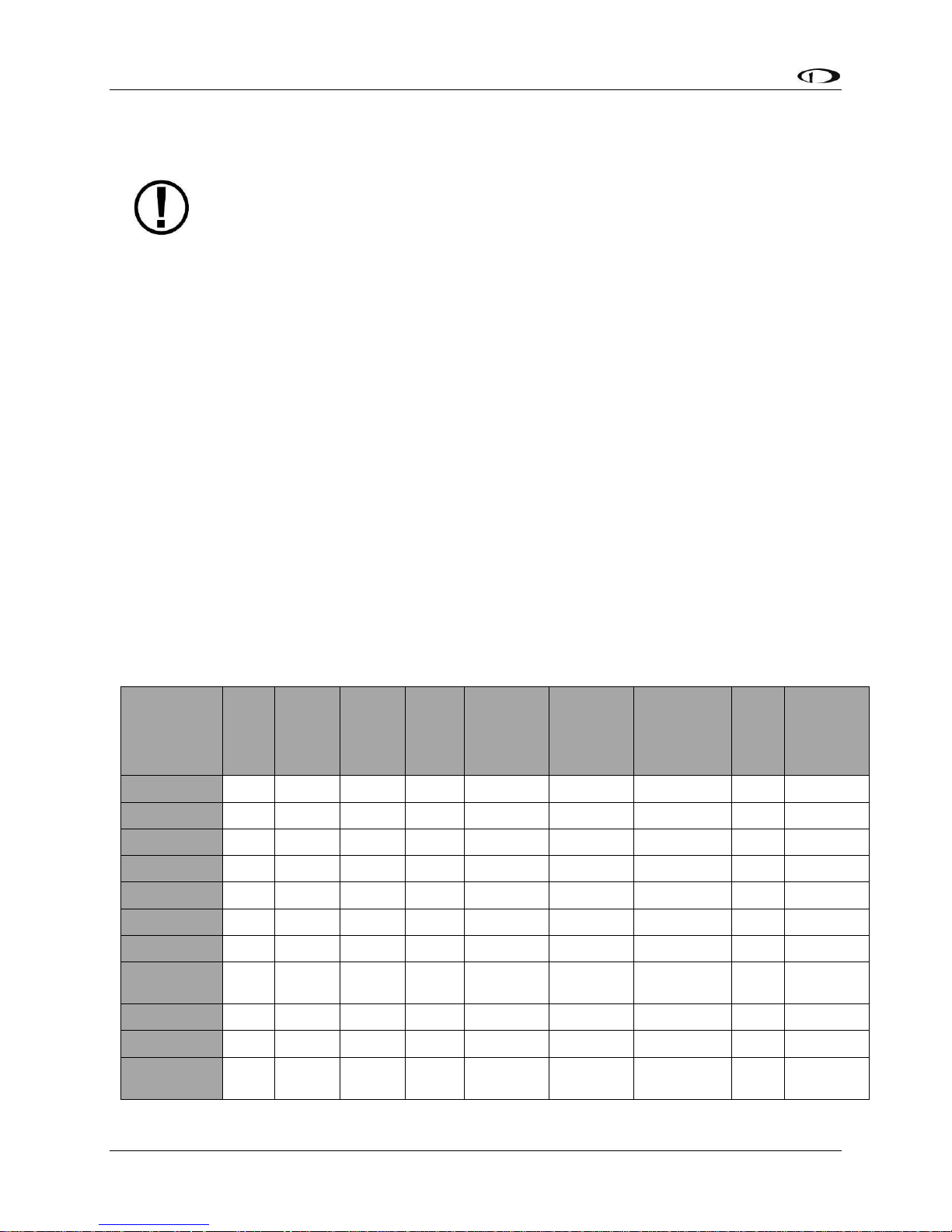
Table 2 describes which inputs and sensors are used within the ADAHRS module to generate
the different displayed instruments.
GPS
Pitot
Static
AOA
Magne-
tometers
Rate
Sensors
Accele-
rometers
OAT
External
Magne-
tometer
Ball
✓
Altitude
✓
Airspeed
✓ ✓
AOA
✓ ✓
Turn Rate
✓
✓
✓
✓
Heading
✓
✓
✓**
✓
✓ ✓
Attitude
✓*
✓
✓
✓
✓
Density
Altitude
✓ ✓
TAS
✓
✓
✓
Winds
✓ ✓ ✓
✓**
✓
✓
Flight Path
Marker
✓ ✓ ✓** ✓ ✓ ✓
Page 19
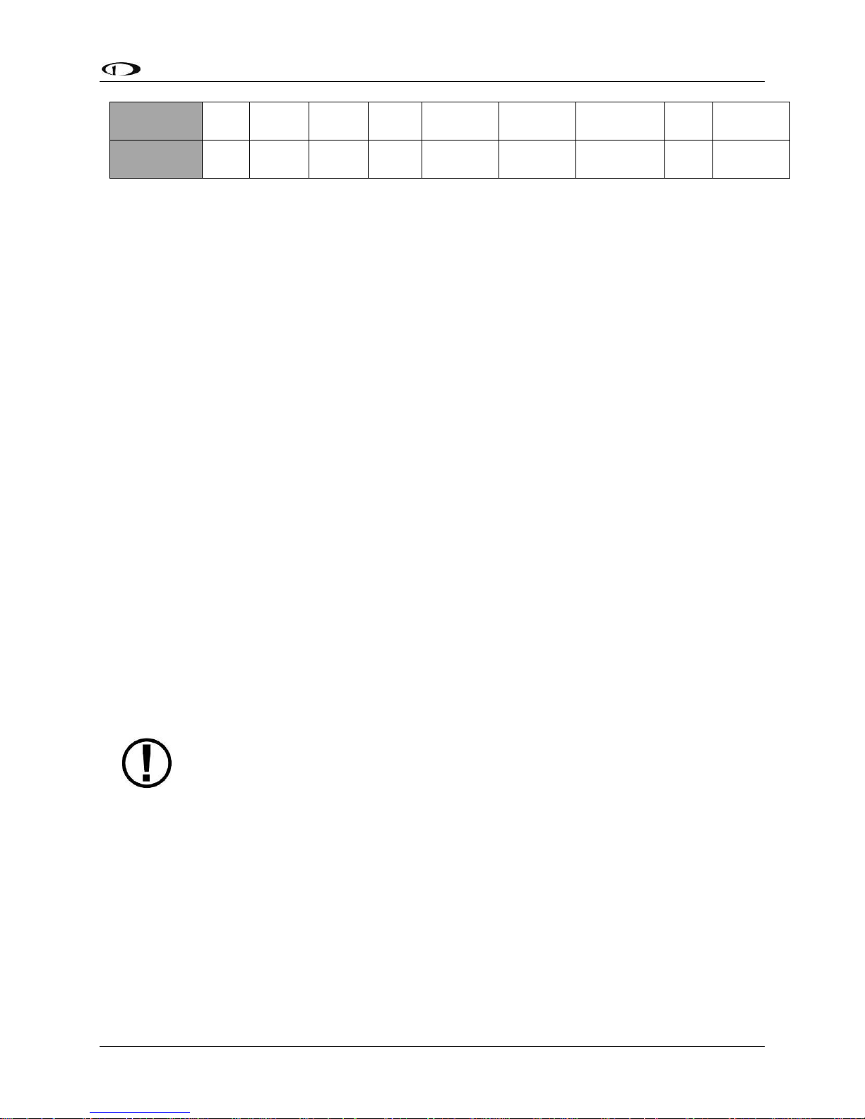
SkyView HDX System Overview
SkyView HDX Pilot’s User Guide – Revision B 2-5
Synthetic
Vision
✓ ✓ ✓ ✓** ✓ ✓ ✓
Ground
Speed
✓
Table 2 – Instruments and Sensors
(*GPS only used when airspeed from pitot and static is not available)
(** SV-ADAHRS-20X Magnetometer deactivated when SV-MAG-236 is installed)
Attitude Calculation
The SkyView artificial horizon display (attitude) is generated via a complex algorithm using a
multitude of sensors as described in Table 2. In normal operation SkyView uses airspeed to
provide superior attitude accuracy. Should airspeed become unavailable due to inadvertent
blockage of the pitot system, GPS ground speed will be used as an attitude aid. GPS ASSIST will
be annunciated on the PFD when this mode is in effect.
Compass Accuracy Effects on Synthetic Vision, Map Performance, and Autopilot
It is critical that the magnetic heading be as accurate as possible for optimal Synthetic Vision
and Moving Map performance. The SV-ADAHRS-20X – and SV-MAG-236 if included in the
system – must be installed correctly, calibrated, and operating well in all attitudes. However, it
is important to note that magnetic heading is not used to aid attitude determination under any
circumstance.
GPS Receivers – SV-GPS-250 and SV-GPS-2020
The SV-GPS-250 and SV-GPS-2020 GPS modules are externally mounted GPS receivers designed
specifically for use with SkyView systems. Both modules are powered by the SkyView HDX
display (and thus will provide position updates when the SkyView HDX display is operating on
battery backup power). Each module outputs GPS data to SkyView in NMEA format and
automatically sets the time on the SkyView HDX display.
To improve positional accuracy, both the SV-GPS-250 and the SV-GPS-2020 receive
Wide Area Augmentation System (WAAS) GPS correction signals (where WAAS is
available). The ability to receive WAAS GPS correction signals does not allow the SV-
GPS-250 or SV-GPS-2020 to be used as a primary navigation source in an IFR
environment where a TSO’d WAAS GPS may be required.
The SV-GPS-2020 became available in early 2016 and provides position updates 4x/second. In
the US, the SV-GPS-2020 GPS receiver is qualified to serve as the required GPS position source
for purposes of meeting the FAA 2020 ADS-B Out mandate. It must be installed in a SkyView
system together with the SV-XPNDR-261 Class 1 Mode-S transponder (see below for more
information) for full ADS-B Out compliance.
Page 20

SkyView HDX System Overview
2-6 SkyView HDX Pilot’s User Guide – Revision B
Engine Data Modules – SV-EMS-220 and SV-EMS-221
The engine gauges on your SkyView Engine Page are generated from the data acquired by the
SV-EMS-220 or SV-EMS-221 Engine Monitoring module and their connected sensors. These
modules support popular four and six-cylinder engine installations and can measure a variety of
engine and environmental parameters such as RPM, manifold pressure, oil temperature and
pressure, exhaust gas temperature (EGT), cylinder head temperature (CHT), fuel levels for
multiple tanks, voltage, current, fuel pressure, fuel flow, carburetor air temperature, coolant
pressure and temperature, flap and trim potentiometers, external contacts, and general
purpose temperature sensors.
Autopilot – Servos
Dynon Avionics SV32, SV42, and SV52 servos enable the operation of SkyView’s integrated
autopilot system. Refer to the SkyView Classic / SE / HDX System Installation Guide for more
information about Dynon Avionics autopilot servos. SkyView HDX can only control Dynon
Avionics servos.
Autopilot Control Panel – SV-AP-PANEL
The SV-AP-PANEL is an optional panel-mounted module that affords dedicated controls for the
SkyView AP’s Expert Mode. The SV-AP-PANEL includes dedicated buttons for engaging the
Flight Director, Autopilot, and all modes including setting up fully-coupled approaches, VNAV,
IAS Hold, and mode sequencing (provided that the necessary IFR navigation sources are
installed in the aircraft). It also has a LEVEL button to immediately return the aircraft to straight
and level flight.
Auto-trim
A secondary function of the SV-AP-PANEL is that it can control one or two electric trim control
motors (replaces a conventional “relay deck”). If this function is installed, the SkyView HDX
Autopilot, when engaged, can also provide automatic trim control – Auto-trim.
Transponders – SV-XPNDR-261 and SV-XPNDR-262
The SV-XPNDR-261 (Class 1) and SV-XPNDR-262 (Class 2) are TSO’d remote mounted Mode-S
transponder modules that, in addition to their transponder capability, contain ADS-B Out
capability via 1090 ES, and TIS traffic input capability (US Only). Note: Only the Class 1 SV-
XPNDR-261 meets the 2020 mandate for ADS-B Out.
ADS-B Receiver – SV-ADSB-470/472
The SV-ADSB-470 and SV-ADSB-472 receive traffic and weather information from the Automatic
Dependent Surveillance – Broadcast (ADS-B) system. ADS-B data allows integrated traffic and
NEXRAD weather data to be displayed on your SkyView HDX display. The SV-ADSB-470 is a 978
MHz (UAT Band) receiver, while the SV-ADSB-472 is a dual band 978 MHz/1090 MHz receiver.
Page 21

SkyView HDX System Overview
SkyView HDX Pilot’s User Guide – Revision B 2-7
Currently the UAT Band is only used in the US.
Com Radios – SV-COM-C25 and SV-COM-X83
The SV-COM-C25 is an integrated VHF Com Radio for SkyView consisting of two modules: the
SV-COM-PANEL, and the SV-COM-425. The SV-COM-C25 has 25 kHz channel spacing and is
intended primarily for aircraft operating in the US. The SV-COM-X83 is an integrated VHF Com
Radio consisting of two modules, the SV-COM-PANEL, and the SV-COM-T8. The SV-COM-X83
has 8.33 kHz channel spacing required for European pilots. Both the SV-COM-C25 and SV-COMX83 can tune frequencies by querying an aviation database installed in SkyView HDX.
Intercom – SV-INTERCOM-2S
The SV-INTERCOM-2S is a two-place stereo intercom that is designed to pair perfectly with your
SkyView System and SkyView Com Radio. It has stereo inputs for SkyView audio alerts, stereo
music, and multiple other mono muting and non-muting inputs.
Knob Panel – SV-KNOB-PANEL
The SV-KNOB-PANEL is an optional panel-mounted module for SkyView. This control panel has
three knobs dedicated to the most common SkyView bug functions – ALT, BARO, and HDG/TRK.
This module is particularly useful in systems with the SkyView autopilot installed. Note that
these bugs can also be adjusted from the SkyView HDX display.
SkyView Video Input Adapter
The optional SkyView Video Input Adapter enables the display of a video signal (must be SVideo or Composite) on your SkyView HDX display in a 50% window (replaces the non-PRIMARY
CONTENT window). If a 100% window is selected, when a video signal is displayed, the 100%
window will be reduced to a 50% window while the video signal is displayed. The SkyView
Video Input Adapter must be inserted into one of the two USB plugs on the back of the SkyView
HDX display during system power-on and while operating.
SkyView Wi-Fi Adapter
The optional SkyView Wi-Fi Adapter allows supported devices, such as Apple iPhones and iPads,
with supported apps, such as ForeFlight, to exchange data with SkyView HDX. For example, you
can compose a flight plan (or, multiple flight plans) in ForeFlight, and after you get to your
plane, ForeFlight can send a flight plan to SkyView. The SkyView Wi-Fi Adapter must be inserted
into one of the two USB plugs on the back of the SkyView HDX display during system power-on
and while operating. For proper function, each display in a SkyView HDX system must be
equipped with a Wi-Fi adapter.
For current devices and apps compatible with SkyView HDX / SkyView Wi-Fi Adapter, see
http://www.dynonavionics.com/skyview-wifi-adapter.php.
Page 22

SkyView HDX System Overview
2-8 SkyView HDX Pilot’s User Guide – Revision B
External Controls, Indicators, Jacks, etc.
The primary harness for each SkyView HDX display provides inputs or outputs for external
buttons, switches, indicators, jacks, etc. Some of these are required (such as Servo Disconnect /
CWS), while others provide optional additional functionality.
As part of your familiarization with your SkyView HDX system, you should identify these
additional controls on your panel or elsewhere in your cabin, and how they interact with your
SkyView HDX system. For additional detail, please reference the SkyView Classic / SE / HDX
System Installation Guide, Appendix K: Switches, etc. External to SkyView Units.
This list does not reference power control breakers, switches, or semi-automated power
control systems such as ADVANCED Control Module or VP-X.
• Autopilot (Servos):
o Servo Disconnect / Control Wheel Steering (CWS) Button
• Heated AOA/Pitot Probe:
o Heated Pitot Off / Failed Warning Indicator
• SV-AP-PANEL (Electric Trim):
o (These controls may be integrated into a “Hat Switch”)
o Pilot Trim Controls: Up, Down, Left, Right
o Copilot Trim Controls: Up, Down, Left, Right
• SV-COM-425 / X83:
o Copilot Headset Jacks
o Copilot Push-To-Talk (PTT) Button (Likely integrated into the stick)
o Pilot Headset Jacks
o Copilot Push-To-Talk (PTT) Button (Likely integrated into the stick)
o Active / Standby Frequency Flip/Flop Button
• SV-D600 / SV-D700 / SV-D900 / SV-D1000 / SV-D1000T / SV-HDX800 / SV-HDX1100:
o Autopilot GO AROUND Button
o Autopilot SV-BUTTON-LEVEL (LEVEL Button)
o SV-KNOB-DIMMER (Dim Control Knob)
o USB Jacks (one per display)
• SV-EMS-220 / 221:
o Master EMS Warning Indicator
• SV-INTERCOM-2S:
o Copilot Push-To-Talk (PTT) Button (Likely integrated into the stick)
o Copilot Headset Jacks
o Music In Jack
o Pilot Push-To-Talk (PTT) Button (Likely integrated into the stick)
o Pilot Headset Jacks
o Radio Select (Transmit) Switch
• SV-XPNDR-261/262:
Page 23

SkyView HDX System Overview
SkyView HDX Pilot’s User Guide – Revision B 2-9
o Standby Switch
o Ident Button
Page 24

Page 25
SkyView HDX Pilot’s User Guide – Revision B 3-1
3. SkyView HDX Display Operation
After reading this section, you should be familiar with basic SkyView HDX display operation. For
details regarding specific procedures, refer to the PFD, EMS, and Moving Map operation
sections.
The SkyView SV-HDX800 and SV-HDX1100 displays are identical in functionality and
presentation. The only difference between the two units is the size of the screen.
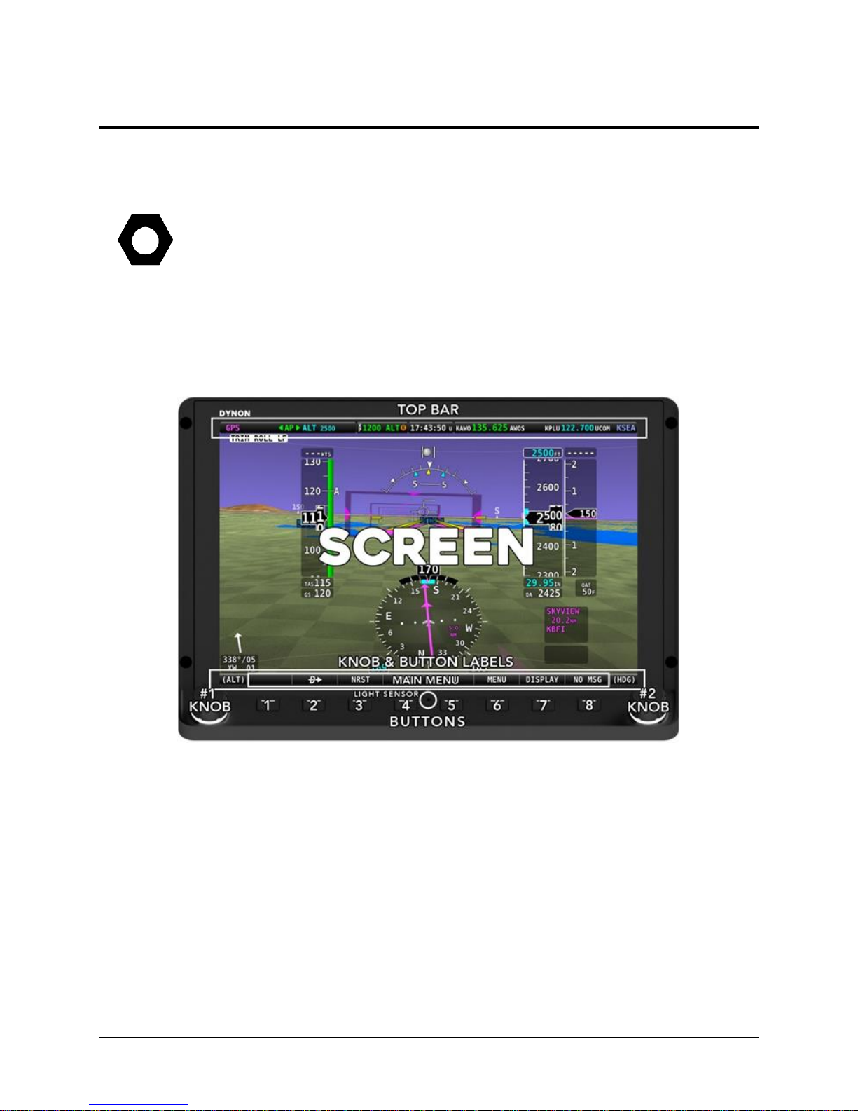
Display Layout
The following image shows the front of a SkyView SV-HDX1100 10” display and its important
parts. Note that the layout of the SkyView SV-HDX800 7” display is the same, just scaled down
for the smaller size of the display.
Figure 1 – SkyView HDX Display Front Bezel Layout (SV-HDX1100 shown)
The structure surrounding the lighted LCD screen itself is referred to as the bezel. All tactile
controls for the system are located on the tilted shelf at the bottom of the bezel. On that shelf
are located 8 buttons, two knobs and an integrated light sensor, whose functions are described
below.
The LCD screen contains three main regions, described from top to bottom:
• The Top Bar – also referred to as the status bar – is user configurable and displays
important contextual information. The status bar will display clock time or a timer
(when running), autopilot status, battery status (when an issue requiring attention is
detected), transponder status, and Com Radio status.
Page 26
SkyView HDX Display Operation
3-2 SkyView HDX Pilot’s User Guide – Revision B
• The largest, central portion of the screen presents PFD, Engine, and Moving Map data,
configuration information, menu and feature control pages, and many system
messages. Its layout is user configurable. Detailed instructions on how to configure the
layout of your screen are presented in a later section of this manual.
• Knob and button labels are arranged across the bottom of the display in a menu bar.
Knob and button functionality is contextual based on what is on screen, and these labels
show the user the current function. For example, the (MAP) label above the right knob
in Figure 1 – SkyView HDX Display Front Bezel Layout (SV-HDX1100 shown) shows that
manipulating that knob will affect what the user can see on the Moving Map page.
Throughout this manual, the buttons are referred to by their relative numbered
position, counting from left to right. Button 1 is the left-most button, and Button 8
is the right-most button.
The bottom menu bar initially displayed once the system is fully powered on is
referred to as the Main Menu.
Each SkyView HDX display has an integrated light-detecting sensor in the front bezel. This light
sensor can be used for automatic backlight level management. Reference the SkyView Classic /
SE / HDX System Installation Guide for instructions on how to configure the display for
automatic backlight level management.
Basic Display Operation Procedures
This subsection covers basic operation procedures for displays. Detailed instructions for various
setup menus and individual menu items are described in the SkyView Classic / SE / HDX System
Installation Guide.
How to Turn the System On or Off
The following table summarizes the procedures for toggling SkyView system power states.
SkyView System
Displays
Toggle SkyView System Power
One display
Toggle primary power state - OR
Toggle display power by pressing and holding button 1
Multiple displays
Toggle primary power state - OR
Toggle all displays off or on by pressing and holding
button 1 on each display.
Table 3 – How to Toggle SkyView System Power State
Page 27
SkyView HDX Display Operation
SkyView HDX Pilot’s User Guide – Revision B 3-3
In the first seconds after turning a SkyView display on, you may see momentary display artifacts
such as multicolored lines and/or flashes of light as the display initializes. This is normal.
How to Manually Adjust the Backlight Brightness or Dim Level
SkyView HDX’s display backlighting is controlled by its ambient light sensor to actively adjust
the brightness based on the current lighting conditions in the cockpit. The brightness is
synchronized across multiple displays and SkyView network panel mounted modules (Com
Radio, Knob Control Panel and AP Control Panel).
If, however, you find that the displays are too bright or not bright enough for you, you can
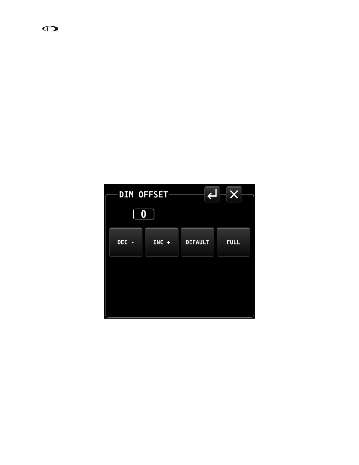
adjust the brightness by selecting DISPLAY (Button 7) on the Main Menu, then touching the DIM
OFFSET icon on the screen. The DIM OFFSET menu, shown in the figure below, allows you to
manually choose an offset from the default brightness values based on current ambient
lighting. This lets you fine tune the brightness of the display to your preference, while still
allowing SkyView to adjust for changing lighting conditions.
Figure 2 – DIM OFFSET control page
To decrease or increase the backlight brightness press DEC- or INC+ icons, respectively.
Alternately, to adjust the backlight brightness with the knob, touch the “value box” (shown in
Figure 2 as “0”) , then rotate the left knob (if the DIM OFFSET menu is displayed on the left side
of the display) or the right knob or rotate the right knob (if the DIM OFFSET menu is displayed
on the right side of the display).
The current offset appears in a window above the DIM knob. Touch the DEFAULT icon to quickly
reset the offset to zero. Touch the FULL icon to quickly set the offset to its maximum. Press the
EXIT icon (“X”) located in the upper right corner of the DIM OFFSET menu to exit.
Page 28

SkyView HDX Display Operation
3-4 SkyView HDX Pilot’s User Guide – Revision B
SkyView will not dim the display to a level that would cause it to be illegible for the ambient
lighting conditions.
On boot up, depending on your SkyView settings, the dimming offset will either be reset to zero
or retained from the previous session. See the SkyView Classic / SE / HDX System Installation
Guide for further information about the brightness settings.
Optionally, the brightness of the SkyView HDX (and the panel mounted modules) can be
adjusted by an external dim control. Also optionally, SkyView HDX’s ambient light sensor can
control other (not manufactured by Dynon Avionics) panel units (and other devices). See the
SkyView Classic / SE / HDX System Installation Guide for details on these options.
Screen Content
Each SkyView HDX display can present many combinations of several types of content:
Primary content – these items are selectable as 100% screen content:
• PFD: A presentation of primary flight instruments and other useful information.
• Engine: combination of engine and aircraft system instruments and fuel computer
data.
• Moving Map: computer-generated GPS moving map with navigation information.
Optional content – these items are available in a 50% wide split content window:
• PFD
• Engine
• Moving Map
• Video: optional display of video from an external camera source (requires optional
USB Video Input Adapter)
Menu and Feature Control pages:
• Many different Icon-based menu pages for controlling various SkyView HDX
features, optional components, and the content of the primary pages.
Setup Menus:
• In-Flight and System Setup pages used for controlling the overall configuration and
behavior of the SkyView system.
Controlling the content and layout of the display is described in later section of this manual.
Button and Knob Operation
Buttons and knobs are used for various functions including powering the unit on and off,
entering and navigating menus, selecting or activating features, and adjusting values.
Page 29
SkyView HDX Display Operation
SkyView HDX Pilot’s User Guide – Revision B 3-5
Button Behaviors
Buttons generally require a single action, that is, to momentarily press and release the button.
Pressing the button will provide a distinct tactile click feedback to the pilot. The click occurs
when the button is fully depressed, but the commanded action does not occur until the button
is released.
When a button is pressed in this manner, a function or action denoted by the label above the
button is invoked. Button labels are contextual and may change dependent on menus and
feature control pages the pilot selects.
A button has a function if there is a label above it. If there is no label, there is no function.
Some buttons have an additional behavior when the button is pressed and held down for 2
seconds. This action is called press-and-hold. An example is Button 1. Press-and-hold action
on Button 1 will power a SkyView HDX display either on or off, depending on its current state.
Additional press-and-hold behaviors for other buttons are described elsewhere in this manual.
Typically press-and-hold behaviors have no on-screen label denoting the action to be
performed. Rather, they are called upon for infrequently used special-purpose actions.
Button labels are called out in all capital letters such as BACK, EXIT, FINISH, and
CLEAR. This guide directs users to press a button by using its label. For example,
when this guide asks you to press FINISH, it is asking you to press the button with
the FINISH label above it.
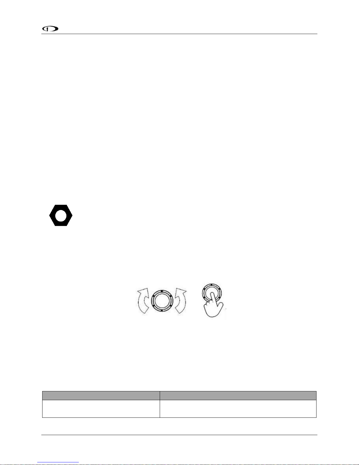
Knob Behaviors
Knobs can be rotated both directions and pushed. The current knob function is indicated by the
label above the knob. Knob function is contextual and can change when the contents of the
screen is changed by the pilot.
Figure 3 – Knob Rotation and Pushbutton Actions
On some screen pages with both vertical lists and a horizontal group of tabs, one or both knobs
can exhibit a push-hold-and-rotate behavior which controls horizontal scrolling of the cursor
across tabs on some feature pages.
The following table summarizes knob behavior is various contexts:
Desired Action
Knob Behavior
Adjust Bug (HDG, ALT, etc)
or BARO value
Rotate knob (labeled with respective function)
Page 30
SkyView HDX Display Operation
3-6 SkyView HDX Pilot’s User Guide – Revision B
Change Map scale
Rotate knob (labeled MAP)
Scroll vertically through a list
(on text menus or data pages)
Rotate knob (labeled CURSR)
Scroll horizontally across tabs on the
NRST or INFO page
Push-Hold-and-Rotate knob (labeled CURSR)
Choose items on icon-based menu and
feature control pages:
• Activate and/or move cursor
• Rotate knob (labeled CURSR)
• Select menu or feature icons
• Push knob (labeled CURSR)
Navigate text menus:
(ie: In-flight Setup; System Setup)
• Move cursor to desired item
• Rotate knob (labeled CURSR)
• Select menu item:
• Push knob (labeled CURSR)
• Retreat to prior menu:
• Push-and-hold knob (for at least ½ second)
Edit a data field:
(ie: Airport ID on INFO page)
• Begin editing:
• Push knob (labeled CURSR)
• Adjust selected character
• Rotate knob (labeled CURSR)
• Advance to next character
• Push knob (labeled CURSR)
• Retreat to prior character
• Push-and-hold knob for at least ½ second
• End editing:
• Touch another field to edit, or select any of
the available action items on the page (eg:
EXIT (menu or icon), ACCEPT, RETURN icon)
Table 4 – Knob Operation Summary
Main Menu (Buttons) Navigation
After the display turns on you will see a screen like the one shown below.
Page 31

SkyView HDX Display Operation
SkyView HDX Pilot’s User Guide – Revision B 3-7
Figure 4 – Displaying Main Menu bar at bottom of screen
This guide refers to the labels above the buttons at the bottom of the screen as the Main Menu
bar, or simply Main Menu. The Main Menu at the bottom of the SkyView HDX screen is quite
simple and intuitive. Four of the seven MAIN MENU buttons – , NRST, INFO, and FPL – are
related to airport information, flight planning, and VFR GPS navigation. Use of these four Main
Menu items is discussed in detail in the MAP and VFR GPS Navigator Operation section.
The following functions are available on the Main Menu bar:
• (blank) – No function
• – Direct-To: Opens the INFO menu for easy access to select and confirm
information about a potential destination.
• NRST – Nearest: Opens a list of various navigational data, such as airports, fixes,
navaids, etc. which may be used as flight plan waypoints, plus other information. Each
list is sorted by proximity to either the aircraft’s position or the position of the panning
cursor on the moving map.
• INFO: Opens the Info page, providing access to all available information for a
designated airport, including optional weather data.
• FPL – Flight Plan: Opens SkyView’s currently entered flight plan.
• MENU – Opens a Menu page providing access to many configuration options, features
and utility functions.
Page 32

SkyView HDX Display Operation
3-8 SkyView HDX Pilot’s User Guide – Revision B
• DISPLAY – Opens a menu page allowing control of the main screen contents and
additional display layout options.
• NO MSG / MESSAGE / CAUTION / WARNING – System Messages. Provides access to a
pop-up page displaying system messages, alerts and warnings. This menu item will be
labeled as “NO MSG” when there are no messages or warnings.
SkyView HDX Touch Features
SkyView HDX was designed with an intuitive and comprehensive touch interface while still
maintaining a full complement of tactile controls. This design assures the pilot has effective use
of all necessary controls in a demanding cockpit environment, especially in turbulence. Even
the physical design of the HDX bezel and button/knob control shelf has been optimized to
assure comfortable use in a bumpy cockpit.
In almost every instance of touchable items or controls, there are tactile controls to accomplish
the same action. Two exceptions to this design objective exist on the Map page, where touch
gestures are the only method for panning the map display and for maximizing/minimizing the
area of the screen occupied by the map. Especially in the case of map panning, the touch
gesture has proven to be more effective in turbulence than nearly any tactile control.
Touch gestures are available throughout the HDX system. They serve as primary methods of
selecting and controlling certain features and actions, as well as providing shortcuts to features
otherwise accessed through various menus.
On the PFD and Map screen pages, touch gestures easily discovered by the pilot simply
touching the screen. On the Map in particular, you will discover many touch gestures familiar
from use of other touch-screen devices such as tablets and smart phones. Touchable regions
and the actions they control are described in greater detail in the respective sections of this
manual covering the PFD and Map.
SkyView HDX also presents many menus, informational pages and feature control pages that
are easily navigated using touch gestures. Many visual clues will alert the pilot to the presence
of touchable gestures. These include graphical icons, selectable tabs, and editable fields, each
with a 3-dimensional shaded box appearance similar to command buttons and boxes on other
computing devices. Touch gestures and touchable items on any given screen page are
described in detail in the respective sections of this manual covering each feature or menu
page.
When “Show Touches” is enabled (in SETUP): a circle, illustrated in
Figure 5 at right, appears at the point of touch contact on the screen
and remains under your finger until contact is removed. This allows
you to see exactly where your finger is making contact with the
objects on the screen. Reference the SkyView Classic / SE / HDX
System Installation Guide for details on enabling or disabling “Show
Touches”.
Figure 5
Show Touches
Enabled
Page 33

SkyView HDX Display Operation
SkyView HDX Pilot’s User Guide – Revision B 3-9
Configuring the Layout of Your SkyView HDX Display
SkyView HDX displays can be configured to present many combinations of PFD, MAP, and
ENGINE data. Other screen components include the presentation of engine instruments along
the bottom of the screen, and a vertical column of GPS navigational data which can be
displayed on the right or left of the display depending on selected layout options. The process
for selecting and arranging these various screen components is described in detail below.
If your instrument panel contains multiple SkyView HDX displays, the layout of each display can
be configured independently.
SkyView HDX can only display data from installed modules. For example, if an SVEMS-220/221 module is not installed, ENGINE and ENGINE BOTTOM BAND will not
be selectable.
In aircraft that have SkyView HDX pre-installed by the aircraft manufacturer, the
SkyView HDX screen layouts may be pre-configured, with changes to the screen
layout restricted. For example, your SkyView HDX display may not offer the option
for the PFD window to not be displayed. Thus for factory-installed SkyView HDX
systems, you may need to contact your aircraft manufacturer to assist you in
changing the screen layout.
Page 34

SkyView HDX Display Operation
3-10 SkyView HDX Pilot’s User Guide – Revision B
Cockpit Role of Each Display
A thorough understanding of this section is critical to using a single or multiple
HDX displays effectively in the cockpit. Please read this section carefully!
Establishing the screen layout for SkyView HDX displays begins with the pilot choosing a cockpit
role for each display in the system. The cockpit role assigned to the display will define the
content of the 100% page when that layout is selected. The cockpit roles from which you may
choose are:
• PFD: Primary Flight Display
• MAP: GPS Moving Map
• ENGINE: Engine Monitoring System
You will also choose whether to present engine instruments in a horizontal band across the
bottom of the display, referred to as the Engine Bottom Band, a key distinguishing
characteristic of the HDX display compared to earlier SkyView systems.
Defining the Default Screen Layout
To define the default layout of a SkyView HDX display (that is displayed when powered up),
select DISPLAY (Button 7) on the Main Menu. Next, tap the SETUP icon at the lower right corner
of the DISPLAY page. The DISPLAY LAYOUT page will appear, as shown below.
Figure 6 – DISPLAY LAYOUT page
The cockpit role for the display, also referred to as Primary Content, is selected in the top row
of buttons on the DISPLAY LAYOUT page. A white box with the title “PRIMARY CONTENT”
Page 35

SkyView HDX Display Operation
SkyView HDX Pilot’s User Guide – Revision B 3-11
groups the three options. The item selected will define the cockpit role and Primary Content of
the display.
Selecting items or command buttons on SkyView HDX’s touchable menu pages can
be accomplished in either of two ways:
• Touch the command button for the desired item. Command buttons are
square or rectangular boxes populated with a text label and sometimes also
with a graphical icon denoting the function, feature or menu controlled by
that button. In Figure 6 above, PFD, MAP, EMS, etc. are command buttons.
• Activate a movable cursor box by rotating the knob labeled CURSR. When
activated, the cursor is denoted by a white box which will form a border
around the selected command button or editable field. Once the desired
item is surrounded by the cursor box, press the knob to select that item.
Throughout SkyView HDX’s menu pages, a green bar at the top of a command
button (such as the PFD command button in Figure 6 above) denotes that the
function of the command button is selected/active. An unlit/no color bar in the
command button (such as the MAP command button in Figure 6 above) denotes
that the function of the command button is not selected/not active.
Next, select whether the primary content should be displayed on the left or right side of the
SkyView HDX display when you choose to split the screen 50% / 50%. That selection is made
from the buttons on the bottom row of the DISPLAY LAYOUT menu page in the box titled
“PRIMARY SIDE”. Select either LEFT or RIGHT. In Figure 6 above, LEFT is selected, with PFD as
the Primary Content.
Finally, choose your preference for three separate items on the middle row of the DISPLAY
LAYOUT menu page:
• SPLIT AT BOOT:
o Set to OFF to have a 100% wide presentation of the selected primary content
displayed at bootup.
o Set to ON to have the display arranged as 50% / 50% windows at bootup.
• MAP INFO COLUMN:
o Set to ON to have the MAP INFO COLUMN displayed.
o Set to OFF for the MAP INFO COLUMN to not be displayed at bootup.
• ENGINE BOTTOM BAND:
o Set to ON to have the ENGINE BOTTOM BAND displayed at bootup.
o Set to OFF to have the ENGINE BOTTOM BAND not displayed at bootup.
Note that selecting ON will override ENGINE being selected as PRIMARY
CONTENT or SPLIT CONTENT (see below).
Page 36

SkyView HDX Display Operation
3-12 SkyView HDX Pilot’s User Guide – Revision B
The figures below show the recommended default DISPLAY LAYOUT selections for a single
SkyView HDX display and the resulting screen presentation.
Figure 7 – DISPLAY LAYOUT (Recommended for single display system)
Figure 8 – Recommended single display layout (Settings shown in Figure 7)
These next figures show the recommended default DISPLAY LAYOUT selections for dual
SkyView HDX displays, with the resulting SkyView HDX displays following.
Page 37

SkyView HDX Display Operation
SkyView HDX Pilot’s User Guide – Revision B 3-13
Figure 11 – Dual display layout – Pilot display (Settings shown in Figure 9)
Figure 10– Dual display
configuration – Copilot display
Figure 9 - Dual display
configuration – Pilot display
Page 38

SkyView HDX Display Operation
3-14 SkyView HDX Pilot’s User Guide – Revision B
Figure 12 – Dual display layout – Copilot display (Settings shown in Figure 10)
Selecting Split Screen Layout
Once the default, or startup, display layout has been defined for each display in the aircraft, you
will choose to periodically change the display layout on the ground or in flight, perhaps
switching between the 100% window and 50%/50% split windows to provide additional
information useful in various phases of flight.
Changes to the display layout other than selecting primary content and the optional
components described previously are made using the DISPLAY page, accessed by pressing
DISPLAY (Button 7) on the Main Menu, as shown below.
Figure 13 – DISPLAY page
Page 39

SkyView HDX Display Operation
SkyView HDX Pilot’s User Guide – Revision B 3-15
With PFD as the Primary Content of your display, select the MAP icon in the SPLIT CONTENT on
the DISPLAY page to add a 50% wide map page to your screen, as shown below.
Figure 14 – 50% PFD / 50% MAP with ENGINE BOTTOM BAND
On the DISPLAY menu page, four items are grouped together in a white box titled SPLIT
CONTENT. The items available in the SPLIT CONTENT box include:
• PFD
• ENGINE
• MAP
• VIDEO
• VP-X
The first three items are not selectable (greyed out) if the same item is already designated as
Primary Content on that display. VIDEO is only selectable if an optional USB Video Adapter is
installed and a properly configured video source is connected. VP-X is only selectable if VP-X is
licensed and installed.
When ENGINE is selected as the SPLIT CONTENT, a 50% engine page is presented. By default,
this page will show engine and aircraft system instruments not already presented on the
ENGINE BOTTOM BAND. An example of the 50% ENGINE split content is shown in Figure 15.
Page 40

SkyView HDX Display Operation
3-16 SkyView HDX Pilot’s User Guide – Revision B
Figure 15 – 50% PFD / 50% ENGINE with ENGINE BOTTOM BAND
If you choose not to use the ENGINE BOTTOM BAND configuration, the 50% ENGINE split
content might become your primary source of engine instruments. In that case you will need to
modify the layout of that page using the EMS SETUP > SCREEN LAYOUT EDITOR in System
Setup.
Returning to Full Screen Layout
To return the display to the 100% layout, select DISPLAY (Button 7) on the Main Menu, then tap
the FULL icon at the top of the DISPLAY page.
Page 41

SkyView HDX Display Operation
SkyView HDX Pilot’s User Guide – Revision B 3-17
Swap Between Two Screens
A swap function typically used to transfer roles of pilots between two screens was added in
SkyView Software version 15.1. If the system has exactly two displays, then the layout of each
display can be swapped back and forth between the two displays.
Figure 16 – DISPLAY menu showing the SWAP button
Reversion Mode
In multi-display SkyView systems, you can specify a reversion mode that automatically changes
the screen configuration to a specific layout when only one display remains powered on.
If reversion mode is enabled and active (other display(s) offline), the following display layout
settings to be displayed can be selected in Setup. This behavior applies equally whether all but
one display in your system has failed, or if you turn on one SkyView display before all others (as
some customers do to see engine instruments before engine start):
• Primary Pane
• Split Content
• Engine Bottom Band
• Primary Side
• Map Info Column
Page 42

SkyView HDX Display Operation
3-18 SkyView HDX Pilot’s User Guide – Revision B
Behavior of ENGINE BOTTOM BAND
The ENGINE BOTTOM BAND is functionally divided into two halves, left and right. The half
underlying the Primary Side of the screen – as selected on the DISPLAY LAYOUT page – is known
as the protected half. The default arrangement of the ENGINE BOTTOM BAND has the required
engine instruments positioned in this portion of the band to assure they normally remain in the
pilot’s view.
Menu and feature control pages activated by the pilot will occupy 50% width of the screen on
the non-primary side, and many require the full height of the screen. When the ENGINE
BOTTOM BAND is enabled, those menu and feature control pages requiring the full screen
height will overwrite the unprotected side of the bottom band, again assuring the most critical
instruments remain in the pilot’s view.
An example of the ENGINE BOTTOM BAND being over-written by the MENU icon page is shown
below.
1.
Figure 17 – ENGINE BOTTOM BAND partial over-written by MENU page
Display of External Video Device
If the optional SkyView Video Input Adapter is installed, VIDEO is one of the SPLIT CONTENT
options on the DISPLAY page. When an external video device, such as a nose camera or belly
camera, is connected and properly configured, the video can be activated by selecting DISPLAY
(Button 7) on the Main Menu, then selecting the VIDEO icon in the SPLIT CONTENT group.
Page 43

SkyView HDX Display Operation
SkyView HDX Pilot’s User Guide – Revision B 3-19
If the ENGINE BOTTOM BAND is active when video is selected, the video page will over-write
the unprotected have of the bottom band. The figure below shows a display with the video
page active.
Figure 18 – optional VIDEO shown in Split Content pane
MENU Page
Button 6 on the Main Menu bar at the bottom of the screen is labeled MENU. Selecting this
item will open an icon-based MENU page for accessing various system controls, sub-menus, and
other tools.
Figure 19 – MENU page
Page 44

SkyView HDX Display Operation
3-20 SkyView HDX Pilot’s User Guide – Revision B
All the items on the MENU page are briefly described below. The function of each item will be
discussed in greater detail in appropriate sections of this manual.
• Top Row – CONTROLS:
o AUTOPILOT: Control panel for autopilot operation
o XPNDR – Transponder: Control panel for setting transponder codes and transmitting
modes
o TIMER: Control panel for a count-up/count-down timer
o Com RADIO: Control panel for the Dynon Com radio
• Second Row:
o PFD TOOLS: Controls for selecting features and display modes for the PFD
o ENGINE TOOLS: Controls for engine and fuel related features
• Third Row – MAP CONTROLS:
o LAYERS: Menu for selecting layer for presentation on the moving map; eg: topography
(terrain), and optional charts (VFR sections, Hi/Lo IFR enroute charts, etc.)
o WEATHER: Controls for the presentation of ADS-B IN weather data on the map and
airport information pages
o USER WAYPOINTS: Controls for managing user-defined navigation waypoints
• Fourth Row – TOOLS:
o CHECK LIST: Menu of user-created check lists
o WEIGHT BAL – Weight and Balance: Customizable weight and balance calculator
o MAINT LOG – Maintenance Logs: Customizable list of aircraft maintenance deadlines,
pilot currency items, etc.
Top Bar (Status Bar)
The Top Bar is the row of information presented across the top of the screen. The middle
portion of the Top Bar always presents a clock or timer, regardless of display layout. Three
other areas of the Top Bar will enunciate the status of Autopilot, Transponder and Com Radio,
provided these optional devices are installed and properly configured.
Each of these four enunciation areas are also touchable and, when touched, opens a control
panel for the respective device. Only clock behavior is described here. The function of the
other three devices enunciated in the Top Bar behavior is covered in respective sections of this
guide.
The clock is always displayed centered at the top of the screen in all screen display modes on
the Top Bar in 24 hour/military format. The time reference can be selected in System Setup to
display either UTC or local time (based on a local offset from UTC).
Time is initially sourced from a GPS feed and is only displayed
when valid GPS data is being received or if (primary or battery)
power has been maintained continuously since valid GPS data
Figure 20 – Example SkyView Clock
Page 45

SkyView HDX Display Operation
SkyView HDX Pilot’s User Guide – Revision B 3-21
was received. If there has never been an initial GPS time set or time has been lost due to loss of
power,”--:--:--“ is displayed. When valid GPS data is received again, time will be displayed.
Reference the SkyView Classic / SE / HDX System Installation Guide for instructions on how to
configure the Top Bar.
Count-Up/Count-Down Timer
The Top Bar clock can be temporarily repurposed to present a configurable count up/down
timer. The Timer function is selected either by touching the clock portion of the Top Bar, or by
selecting MENU (Button 6) on the Main Menu bar, then selecting the TIMER icon to present the
TIMER control page.
While the TIMER page is displayed, the clock in the top bar displays TIMER information instead
of the local or UTC clock that is normally shown. Leaving the timer menu will restore the clock if
a timer is not running. Examples of the timer display are shown below.
Figure 21 – Up Timer
Figure 22 – Down Timer
Figure 23 – Down Timer Expiring
The TIMER page includes the following controls:
• RUN: Touching the RUN icon will start the timer.
• STOP: Touching the STOP icon will stop the timer.
• UP: Touch the UP icon to toggle the timer to count up.
• DOWN: Touch the DOWN icon to toggle tie timer to count down.
• ZERO: Resets the TIME field to zero.
• LAST: When DOWN is selected, the LAST icon resets the TIME field to the last value it
was set to before it was started.
• Editable TIME field: The TIME field is only editable when DOWN is selected. It
establishes the starting value for the count-down timer. Touch the Time field to begin
editing. The “minutes” character will become highlighted. Change the value by rotating
the knob labeled “CURSR”. Select the “seconds” character in the time value by pushing
the knob or touching the field again.
o When a DOWN timer reaches zero, an audible “timer expired” message is played
(if audio output is connected), the timer flashes white for a few seconds, and a
“timer expired” alert is annunciated in the message alert area. Press button 8 to
view and acknowledge this alert. If a DOWN timer is not reset, the timer will
continue to count down negatively.
o When an UP timer is running, it will stop at 99:59 minutes.
Page 46

SkyView HDX Display Operation
3-22 SkyView HDX Pilot’s User Guide – Revision B
Figure 24 – TIMER control page
If the TIMER page is closed while the timer is running, the TIMER will continue to be displayed
in the TOP BAR. It will continue to be displayed until the TIMER page is opened again and the
timer is stopped. Any time the TIMER page is closed while the timer is stopped, the TOP BAR
will return to displaying the normal clock.
SETUP Menu Navigation
The SkyView HDX system relies on a series of setup menus for configuring the system for initial
use and for defining the behavior of various features and components. These setup items are
not accessed directly by any of the standard menus or pages. Rather, all setup items are
available in System Setup, which is accessed by concurrently pressing-and-holding Buttons 7+8
for approximately two seconds.
When the aircraft is stationary on the ground, this button combination will change the entire
display to present the SETUP MENU screen, shown below.
Page 47

SkyView HDX Display Operation
SkyView HDX Pilot’s User Guide – Revision B 3-23
Figure 25 – System SETUP MENU
While the SETUP MENU is displayed, none of the regular display contents are available to the
pilot. Use of System Setup is fully covered in the SkyView Classic / SkyView SE / SkyView HDX
System Installation Guide.
Some portion of System Setup items are useful or necessary to the pilot in flight. Those items
have been added to an IN FLIGHT SETUP MENU. This menu is also accessed by concurrently
pressing-and-holding Buttons 7 and 8. The system will detect the aircraft’s flight state and
present the appropriate menu to the pilot. An example of the IN FLIGHT SETUP MENU is shown
below.
Page 48

SkyView HDX Display Operation
3-24 SkyView HDX Pilot’s User Guide – Revision B
Figure 26 – IN FLIGHT SETUP MENU
Note that the bottom item in the IN FLIGHT SETUP MENU provides access to the full screen
SETUP MENU. When in flight pilots should only choose this item carefully and deliberately.
Navigation of both the In Flight and System setup menus is identical. As each menu page is
displayed, the top item in the list will be highlighted by a white cursor bar. Move the cursor up
or down to the desired item by rotating either knob (labeled “CURSR”). Select the desired item
by pushing the knob. The next menu – referred to as a sub-menu – will be displayed.
In the case of the IN FLIGHT SETUP MENU, each successive sub-menu will replace the previous
menu and will be presented only in the 50% wide non-primary side of the screen. In the fullscreen System SETUP MENUs, the current menu is presented in the left half of the screen, and
the prospective sub-menu in the right half. When a menu selection is made by pushing the
knob, the selected sub-menu will move to the left half of the screen, and a new menu will
appear on the right.
In both the IN FLIGHT and System setup menus, pushing-and-holding the knob for one second
will return to the previous menu. Both menu systems also make use of the bottom menu bar to
present some navigation selections, such as BACK and EXIT.
The following table summarizes menu navigation IN FLIGHT and System setup menu navigation.
Page 49

SkyView HDX Display Operation
SkyView HDX Pilot’s User Guide – Revision B 3-25
Desired Menu Action
User Action
Enter the Setup Menu
Simultaneously press and hold buttons 7 and 8
(if airspeed is greater than zero, you will enter the
In Flight Setup Menu)
Scroll through different menus
Turn either knob
Enter menu
Push either knob
Return to previous menu
Push-hold either knob (saves settings)
OR
Press BACK (saves settings)
OR
Press CANCEL (does not save settings)
Save adjusted value
Press ACCEPT
Reset adjustable value
Press DEFAULT
Save settings and return to Main
Menu
Press EXIT
Table 5 – Menu Navigation Summary
Non-Menu Operations (“Hidden” Functions)
The HDX display relies on a few button operations to perform actions that are not indicated to
the pilot through on-screen labels or other markings. One of those unlabeled button
operations was described above for accessing SETUP menus.
The table below explains available non-labeled button operations.
Page 50

SkyView HDX Display Operation
3-26 SkyView HDX Pilot’s User Guide – Revision B
Button(s)
Action
Pre-condition
Result
N/A
Apply power to
display(s)
N/A
Display powers ON
N/A
Disconnect power to
display(s); turn off
avionics circuit
breaker or power
switch
SV-BAT-320 Backup
Battery Installed,
aircraft is in flight:
Warning is displayed:
“POWERING DOWN IN 30
SECONDS”.
Press Button 8 to acknowledge
Display remains powered ON
(for duration of SV-BAT-320)
SV-BAT-320 Backup
Battery Installed,
aircraft is stationary:
Warning is displayed:
“POWERING DOWN IN 30
SECONDS”.
Within 30 seconds, press
Button 8 to acknowledge.
If Button 8 is not pushed within
30 Display remains powered
ON (for duration of SV-BAT-
320)
SV-BAT-320 Backup
Battery Not Installed
Display powers off
1
Push for approx. 2
seconds
If display is OFF
powers display ON.
If display is on
powers display OFF.
1+2+5
Push simultaneously
and release
Reboots display; equivalent to
powering off and on again.
2+7
Push simultaneously
and release
If USB flash drive is
plugged in
records “screenshot” file to the
USB flash drive. Message:
SCREENSHOT SAVED TO USB
DRIVE
If no USB flash drive
plugged in
Message: SCREENSHOT
MISSING USB DRIVE
7+8
Push simultaneously
for approx. 2
seconds
If in flight
opens
IN FLIGHT SETUP MENU
If stationary
opens
SETUP MENU
Table 6 – Non-Menu Operations (“Hidden” Functions)
Page 51

SkyView HDX Pilot’s User Guide – Revision B 4-1
4. PFD Operation
This section explains the layout of the PFD page, including the Synthetic Vision (SynVis)
functions, PFD symbology, and explains how to adjust the various bugs.
Synthetic Vision depictions of terrain, runways, obstacles, and other information
are meant as informational aids only. These depictions should not be used as the
primary means for obtaining situational awareness of these features in flight.
The terrain data displayed in SkyView HDX is obtained from third party sources.
Dynon Avionics cannot independently verify the accuracy of terrain data at all
geographical points.
SkyView HDX’s PFD requires data from an SV-ADAHRS-20X module.
SkyView HDX’s display of Synthetic Vision, ground speed, and HSI requires valid GPS
data.
PFD Page Layout
The PFD page, as shown in the figure below, displays important flight information and Synthetic
Vision.
Figure 27 – SkyView PFD
Page 52

PFD Operation
4-2 SkyView HDX Pilot’s User Guide – Revision B
The primary information shown on the PFD includes:
• Synthetic Vision
• Airspeed Indicator, Airspeed Bug, and Airspeed Trend Rate
• Attitude Indicator with Extreme Pitch Warning Arrows (not shown in Figure 27; see
Figure 74 for an illustration of the Extreme Pitch Warning Arrows).
• Flight Path Marker
• Altimeter with Altitude Bug, Altitude Trend Rate, Barometer Setting, and Density
Altitude
• Vertical Speed Indicator with Vertical Speed (VS) BUG
• Heading Indicator/Directional Gyro with Heading (HDG) BUG
• Slip/Skid Ball
• Angle of Attack Indicator
• OAT
• Winds Aloft magnitude and vector
PFD TOOLS Menu Page
Many components of the PFD are selected and controlled on the PFD TOOLS menu. Access this
menu by selecting MENU (Button 6) on the Main Menu, then selecting the PFD TOOLS icon on
the second row of that menu. The PFD TOOLS menu page is shown below.
Figure 28 – PFD TOOLS menu page is shown
Each of the options on the PFD TOOLS menu is discussed in more detail in later sections of this
manual.
Page 53

PFD Operation
SkyView HDX Pilot’s User Guide – Revision B 4-3
PFD Symbology
Bugs
The SkyView PFD uses the following bugs to control the SkyView AP (if Dynon Avionics servos
are installed to provide Autopilot functionality).
• Altitude (ALT)
• Barometer (BARO)
• Course (CRS)
• Heading (HDG) / Track (TRK)
• Indicated Airspeed (IAS)
• Minimum Descent Altitude (MDA)
• Vertical Speed (VS)
See Figure 28
BUGS
Knob
Function
Menufor the locations on the PDF of the various BUGS.
How to Enter the BUGS Knob Function Menu
Knob Function menus for each knob are used to specify which bug or parameter the
knob adjusts if turned. For example, Knob 1 could be set to adjust the heading bug
and Knob 2 could be set to adjust the Altitude bug.
Figure 28 shows the Knob Function menu when all possible bugs and functions of
the SkyView HDX are enabled (via the BUGS on the PFD TOOLS page) and selectable
for use. Depending on which bugs you have enabled, the BUGS Knob menu on your
SkyView HDX display may contain fewer items than shown in Figure 28.
To change the function of a knob:
1. Push on the desired knob to open the Knob Function menu.
2. Rotate the knob to highlight the preferred Knob Function.
3. Push on the knob a second time to change the Knob Function.
To select which BUGS are enabled for selection on the BUGS Knob, select MENU
(Button 6) on the Main Menu, then select the PFD TOOLS icon, then BUGS icon. On
the BUGS menu page, select/deselect the various BUGS per your preferences.
NOTE: The selection of active bugs on the KNOB function list is a local display
setting. That is, changing the bugs included in the KNOB function list on one display
will have no effect on the contents of the KNOB function list other SkyView HDX
displays in the aircraft.
If the MAP window is displayed, the knob closest to the MAP is labeled (MAP) and
is used to change the scale of the MAP page.
Figure 29
BUGS
Knob
Function
Menu
Page 54

PFD Operation
4-4 SkyView HDX Pilot’s User Guide – Revision B
To change the function of a knob using touch, merely tap the element on screen for which you
wish to assign function control to the knob. For example, to change the knob function to BARO
bug, touch the BARO window on screen to re-assign the knob function to BARO bug. Touching
the bug value box will only have effect if that bug is active in the KNOB function list.
Figure 30 – Touchable on-screen regions that change Knob BUG Function; See Below for Legend
Legend for Figure 30 – Touchable on-screen regions that change Knob BUG Function; See Below
for Legend:
1 – IAS (Indicated Air Speed)
2 – ALT (Altitude)
3 – VS (Vertical Speed)
4 – HDG (Heading; same as 7)
5 – MDA (Minimum Descent Altitude)
6 – BARO (Barometer)
7 – HDG (Heading; same as 4)
8 – CRS (Course)
When the 100% PFD window is used, touching the screen element will change the
function of the Left knob. When a 50% / 50% window is used, the function of the
knob on the side of the PFD is changed.
Page 55

PFD Operation
SkyView HDX Pilot’s User Guide – Revision B 4-5
Airspeed Indicator
The Airspeed Indicator is displayed on the left side of the
PFD and incorporates an airspeed tape with a digital
readout, true airspeed (TAS), airspeed trend indicator,
and airspeed bug. Figure 30 is an example Airspeed
Indicator.
Units can be set to miles per hour, nautical miles per hour
(knots), or kilometers per hour. Reference the SkyView
Classic / SE / HDX System Installation Guide for
instructions on how to change the displayed units.
The airspeed tape displays indicated airspeed including
gray, white, green, yellow, and red ranges
to provide a graphical representation of
aircraft speed in relation to the aircraft's
limits. These ranges are controlled by
setting the airspeed limitations for the
aircraft. Performance speeds (Vx, Vy and
Va) are displayed as a letter on the right
side of the airspeed tape. Reference the
SkyView Classic / SE / HDX System Installation Guide for instructions on how to
configure the airspeed limitation color thresholds.
Airspeed will display “---” at zero through 20 knots, at which point it will become live. Once live,
it will display airspeeds down to 15 knots. Below 15 knots, “---” will again be displayed.
The indicated airspeed (IAS) digits scroll up and down, simulating an analog Airspeed Indicator.
The rate of change of the digits provides a sense of the increase or decrease in speed.
The airspeed trend indicator is displayed as a magenta bar on the airspeed tape. It grows
proportionally in the direction of the rate of change (acceleration or deceleration). The airspeed
trend indicator is scaled to indicate a 6-second airspeed trend which means
that if the acceleration is kept constant, the airspeed will end up at the
number indicated at the end of the trend line after 6 seconds have passed.
True Airspeed (TAS) is digitally displayed at the bottom of the airspeed tape.
If configured with a GPS, Ground Speed (GS) is also displayed under the True
Airspeed.
In some aircraft, Vne (Redline) is limited by TAS instead of IAS. When
configured to indicate Vne as TAS, the Red airspeed range will dynamically
adjust so that the TAS limit is what starts the red airspeed range. Additionally,
a Red marker is shown at the IAS that Vne would be at when at sea-level on a
standard day, which is when TAS equals IAS. This lets you quickly see the
difference between your current Vne as TAS and Vne as IAS. In the example
Figure 31 – Example
Airspeed Indicator
Figure 32 – Example V speeds
Figure 33 – Vne as TAS
Page 56

PFD Operation
4-6 SkyView HDX Pilot’s User Guide – Revision B
shown here, the Vne is configured to be based on a TAS of 190. However, because the aircraft is
at altitude, that TAS occurs at a lower IAS. In this case, you can see that the red range has been
lowered to an IAS of 173, which is where the TAS has reached its limit of 190.
Airspeed Bug
The airspeed bug is displayed in cyan (light blue) on the airspeed tape and its associated digital
readout is displayed at the top of the Airspeed Indicator.
To set the airspeed bug:
1. Enter the Knob Function Menu.
2. Rotate the knob to move the cursor up or down to highlight (IAS).
3. Push the knob to close the menu (this is optional; the menu will close after
approximately 5 seconds). This step assigns that knob to IAS BUG.
(IAS) will now display just above that knob. The airspeed bug setting on the PFD will be outlined
to signal that it is selected. Turn that knob to adjust the airspeed bug. Note that while the
airspeed bug is changing, its display window lights up in cyan to draw your attention to it.
An alternate method of setting the Airspeed bug is to synchronize the bug to
current airspeed by pushing the knob for ½ second. After the bug is synchronized
an “IAS SYNC” message will appear above the knob.
Attitude Indicator
Attitude indicator symbology is displayed on PFD and incorporates a roll scale with roll pointers
and a zero bank angle reference, pitch scale with horizon lines, and water line symbology.
Figure 34 is an example SkyView attitude indicator.
Figure 34 – Example Attitude Indicator
Page 57

PFD Operation
SkyView HDX Pilot’s User Guide – Revision B 4-7
The roll scale contains tick marks at 10, 20, 30, and 60 degrees and larger white triangles at 0
and 45 degrees. The roll pointer (small yellow triangle on the bottom side of the roll scale)
points to your current bank angle. The roll scale will rotate 360 degrees. When the aircraft is
wings level, the roll pointer aligns with the roll scale zero point. The water line symbology also
indicates wings level flight.
The pitch scale has tick marks in 2.5-degree increments, and every 10-degree tick mark provides
a horizon line across the width of the screen. If the displayed pitch on the screen requires
adjustment to accurately depict the aircraft’s attitude in level cruise flight, use the Flight Angle
Pitch Adjust Page in the In Flight Setup Menu (IN FLIGHT SETUP MENU > FLIGHT ANGLE PITCH
ADJUST…). The pitch may be adjusted to a maximum of ±20 degrees.
NOTE: the Flight Angle Pitch Adjustment is only intended to adjust for minor
differences in the aircraft’s attitude at various weights or CG locations. It is not
intended to compensate for an ADAHRS which is improperly oriented with the
aircraft’s longitudinal axis.
The extended zero pitch line features heading markers every 30 degrees to help maintain
directional awareness when attention is being paid to the attitude indicator.
Attitude Rate Limit
SkyView HDX’s ADAHRS will operate normally at rotational rates of up to 150 degrees per
second in any axis. If the aircraft’s rotational rate exceeds 150 degrees per second – as can
happen in a well-developed spin or when performing aggressive aerobatic maneuvers – the PFD
page will annunciate “ATTITUDE RECOVERING”. During this time, SkyView HDX’s attitude
indication may be degraded and other instruments should be used to maintain safe flight.
After straight and level flight is restored for a few seconds, the ATTITUDE RECOVERING message
will disappear. Full performance of the attitude indication is restored. This requires no
additional action by you.
GPS Assist
In the event of airspeed loss (due to icing or other blockage) an accurate attitude is maintained
if there is an accurate GPS ground speed source. When in this mode, a magenta GPS ASSIST
message is displayed on the PFD and the ground speed is displayed below the indicated
airspeed (IAS). If the connectivity with the GPS fails while in GPS assist mode, the attitude
continues to be displayed, using the last known GPS ground speed as a reference. This mode is
flagged on the horizon with a yellow CROSS CHECK ATTITUDE message. In the very rare case
that this sequence of events occurs, the ADAHRS’ attitude accuracy is reduced; use other
references in the aircraft to cross-check against the SkyView display.
Note that due to a limitation of the SV-GPS-250/2020 hardware, it cannot be used for GPS
Assist above 415 knots ground speed if it is being used as the GPS source
Page 58

PFD Operation
4-8 SkyView HDX Pilot’s User Guide – Revision B
Flight Path Marker
The flight path marker as shown in Figure 34 is an icon that is superimposed on
the PFD. It depicts the actual trajectory that the aircraft is flying through space. In
contrast, the attitude indicator displays the direction that the aircraft is pointed.
The flight path marker is extremely helpful in correlating and distinguishing
between aircraft attitude and flight path, giving you a better understanding of
what the aircraft is doing. Given this, the marker can also be a valuable aide for
avoiding terrain when used with Synthetic Vision.
The flight path marker can be enabled or disabled through the setup menus. Reference the
SkyView Classic / SE / HDX System Installation Guide for information about this setting. To
calculate and display the Flight Path Marker, SkyView HDX requires an indicated airspeed that is
not zero or a GPS ground speed of more than 25 kts. The flight path marker also uses vertical
speed, magnetic heading, GPS ground speed and ground track to calculate its guidance. The
flight path marker will not appear if any of these sources are unavailable.
Several examples of Flight Path Marker behavior:
• If the aircraft’s nose is pitched up, but the marker stays on the horizon, this indicates
that the aircraft is not climbing or descending. You will see this behavior during slow
flight.
• If the aircraft is neither climbing nor descending, the flight path marker will align with
the zero-pitch line. Many aircraft do not cruise at an exactly level attitude. In this case, it
is normal to have a slightly pitched up or pitched down attitude indication, even though
the flight path marker indicates the aircraft is indicating no vertical trajectory.
• If the marker is to the left or right of the attitude indicator’s aircraft symbol, this
indicates that the path over the ground is different than the direction the aircraft is
pointing. This depicts the effects of wind or a slip attitude.
• If the aircraft is climbing out of a canyon and the marker is above the terrain ahead, this
indicates that the aircraft, at its current trajectory, will clear that terrain.
• If the aircraft is climbing out of a canyon and the marker is overlaid on the terrain
ahead, this indicates that the aircraft, at its current trajectory, will impact the terrain.
• If the marker is pointed at a runway threshold during an approach, that is where you will
be when you land if you keep the same approach path to the runway.
Altimeter
The altimeter is displayed on the right side of the PFD. It incorporates an altitude tape and
digital readout, Density Altitude (DA), barometer setting, and altitude bug. Figure 35 is an
example SkyView HDX altimeter.
The altitude tape displays 200 units above and below the current altitude digital readout. Each
tick represents 25 units, with every 50-unit tick drawn slightly longer to differentiate them.
Figure 35 –
Example Flight
Path Marker
Page 59

PFD Operation
SkyView HDX Pilot’s User Guide – Revision B 4-9
Units can be set to feet or meters. Reference the SkyView Classic / SE / HDX System Installation
Guide instructions on how to change the displayed units.
The digital readout scrolls up and down in the manner of an analog altimeter. The rate of
change of the digits provides a sense of the increase or decrease in altitude.
An altitude trend indicator based on current vertical speed is represented as a magenta bar on
the altimeter. It grows proportionally as your climb or descent rate increases/decreases. The
altitude trend indictor is scaled to indicate a 6-second altitude trend. This means that if current
rate of altitude change is kept constant, the altitude will end up at the number indicated at the
end of the trend line after 6 seconds have passed.
DA will display “----” if an OAT is not valid. Since relative humidity is not readily available to
SkyView in flight, density altitude is calculated using an approximation. The results of SkyView
HDX’s DA computation will closely match a traditional handheld E6B.
Setting Barometer (BARO)
To change the barometer setting:
1. Enter the Knob Function Menu.
2. Rotate the knob up or down to highlight (BARO).
3. Push the knob to close the menu (this is optional; the menu will close after
approximately 5 seconds). This step assigns that knob to BARO BUG.
(BARO) will now display just above that knob. The barometer setting on the PFD will be outlined
to signal that it is selected. Rotate the BARO BUG knob to adjust the barometer setting. Note
that while the barometer setting is changing, its display window lights up in cyan to draw your
attention to it.
Figure 36 – Altimeter
Page 60

PFD Operation
4-10 SkyView HDX Pilot’s User Guide – Revision B
If your panel has the optional SV-KNOB-PANEL Knob Panel installed, simply rotate
the SV-KNOB-PANEL’s BARO knob to adjust the BARO BUG.
To quickly sync the Barometer BUG (see Table 7 below for synchronization criteria), push and
hold the knob (½ second click).
If your panel has the optional SV-KNOB-PANEL Knob Panel installed, simply push
and hold the BARO knob (½ second click) to sync the Barometer BUG (see Table 7
below for synchronization criteria).
When BARO is synchronized, a BARO RESET message will appear above the knob.
If none of the conditions below are met the altimeter will not synchronize and “NO SYNC” will
appear in the altimeter box on the PFD. Table 7 below details how the BARO setting is
synchronized:
With SV-ADSB-470/472 Installed
Without SV-ADSB-470/472
Installed
On the Ground:
Adjusts the altimeter based on the current GPS Altitude. After the
(BARO) is synchronized a GPSALT message will appear in the altimeter
box on the PFD.
In the Air:
Adjusts the altimeter based on the
METAR of the flight plan's
destination airport if within 20nm.
If there is no flight plan waypoint or
it is too far away then the altimeter
is set to the nearest ADS-B METAR
within 100nm with a valid altimeter
setting. After the (BARO) is
synchronized a SYNC message will
appear in a window above the knob
and the airport identifier will
appear in the altimeter box on the
PFD.
Adjusts the altimeter to the
standard pressure setting (i.e.,
29.92 in Hg, 1013 mbar, or 760
mm Hg).
Above 18,000
ft indicated
altitude
Resets the altimeter to standard pressure altitude for use in the flight
levels (i.e., 29.92 in Hg, 1013 mbar, or 760 mm Hg).
Table 7 – Conditions for Synchronizing BARO BUG
Altitude BUG
The Altitude BUG is displayed in cyan (light blue) on the altitude tape and its associated digital
readout is displayed at the top of the Altimeter. The Altitude BUG is used as a target for the
Pitch axis of the SkyView HDX Autopilot when a pitch axis servo is installed.
Page 61

PFD Operation
SkyView HDX Pilot’s User Guide – Revision B 4-11
The reaction of the Autopilot to changing the Altitude BUG depends upon:
• The state of the AP’s Pitch axis, and
• The AP’s armed mode of operation, and
• The current state of the aircraft.
See the Autopilot Operation section later in this guide for more information about
how the Autopilot uses the Altitude BUG.
To set the Altitude (ALT) BUG:
1. Enter the Knob Function Menu.
2. Rotate the knob to highlight (ALT).
3. Push the knob to close the menu (this is optional; the menu will close after
approximately 5 seconds). This step assigns that knob to ALT BUG.
(ALT) will now display just above that knob. The Altitude BUG setting on the PFD will be
outlined to signal that it is selected. Turn the knob to adjust the Altitude BUG. Note that while
the Altitude BUG is changing, its display window lights up in cyan to draw your attention to it.
If your panel has the optional SV-KNOB-PANEL Knob Panel installed, simply rotate
the SV-KNOB-PANEL’s ALT knob to adjust the ALT BUG.
To quickly sync the Altitude BUG with the current altitude, press and hold the ALT knob (½
second click).
If your panel has the optional SV-KNOB-PANEL Knob Panel installed, simply push
and hold the ALT knob (½ second click) to sync the Altitude BUG with the current
altitude.
After the Altitude BUG is synchronized an “ALT SYNC” message will appear above the knob.
Altitude Alerter
SkyView HDX can be configured to audibly alert as the aircraft changes altitude in relation to
the Altitude BUG. When the Altitude BUG is active, audio out is configured, and the altitude
alerter is configured, an audio alert of “APPROACHING ALTITUDE” is spoken as the aircraft flies
within a user-selectable distance of the setting of the Altitude BUG. Similarly, an audio alert of
“LEAVING ALTITUDE” is spoken as the aircraft flies away from the setting of the Altitude BUG by
more than a user-selectable distance. The altitude thresholds that trigger the two above alerts
are individually configurable/ The altitude alerter function is not dependent on the state of the
Autopilot (engaged, vs not engaged). See the SkyView Classic / SE / HDX System Installation
Guide for details on how to configure the altitude alerter.
Minimum Descent Altitude (MDA) BUG
The Minimum Descent Altitude (MDA) BUG allows you to set a bug to alert when approaching a
set altitude. This is typically used during approaches to remain aware of approach minimums.
This bug is separate from the altitude bug, which is used to control the autopilot.
Page 62

PFD Operation
4-12 SkyView HDX Pilot’s User Guide – Revision B
When the MDA BUG is set:
• When the aircraft descends through 200 feet above the MDA bug:
o An “APPROACHING MINIMUMS” audio alert is spoken.
• When the aircraft descends through the MDA bug:
o A “MINIMUMS” audio alert is spoken.
o A visual “MINIMUMS” alert is displayed on the PFD as seen in the figure below.
0Figure 37 – MDA Bug and “MINIMUMS” Alert
Vertical Speed Indicator
The Vertical Speed Indicator (VSI) is displayed to the immediate right of the Altimeter and
incorporates a vertical speed tape, vertical speed pointer (with digital readout), and bug. Figure
37 is an example SkyView HDX VSI.
The VSI tape can display ±1000 units, ±2000 units, or ±4000 units. Units can be set to feet or
meters. Reference the SkyView Classic / SE / HDX System Installation Guide for instructions on
how to change the displayed units and the indicator scale.
Figure 38 – Example Vertical Speed Indicator.
Partial Screen PFD Version on Right.
Page 63

PFD Operation
SkyView HDX Pilot’s User Guide – Revision B 4-13
The vertical speed pointer scrolls up and down the VSI tape, simultaneously displaying the
instantaneous vertical speed in both analog and digital formats. If there is very little or no
vertical speed, the pointer appears blank. When the PFD is configured as a 50% page, the digital
vertical speed readout appears above or below the VSI tape as shown in Figure 37, but the
analog sliding behavior of the pointer is the same as described above. When the Vertical Speed
Required to Destination info item is active on the Map a magenta line is drawn on the VSI at
that speed.
Figure 39 – Vertical Speed Required to Destination
Vertical Speed BUG
The Vertical Speed BUG is displayed in cyan on the right side of the VSI tape and its associated
digital readout is displayed at the top of the VSI. The Vertical Speed BUG is used by the Autopilot
as a target vertical speed when it is climbing or descending (when a Pitch axis servo is installed).
To set the VS BUG:
1. Enter the Knob Function Menu.
2. Rotate the knob to highlight (VS).
3. Push the knob to close the menu (this is optional; the menu will close after
approximately 5 seconds). This step assigns that knob to (VS).
(VS) will now display just above that knob. The Vertical Speed BUG setting on the PFD will be
outlined to signal that it is selected. Rotate the knob to adjust the Vertical Speed BUG. Note
that while the vertical speed bug is changing, its display window lights up in cyan to draw your
attention to it.
You can synchronize the vertical speed bug with the current vertical speed by pushing and
holding the VS knob (½ second click).
After the Vertical Speed BUG is synchronized, a “VS SYNC” message will appear above the knob.
Page 64

PFD Operation
4-14 SkyView HDX Pilot’s User Guide – Revision B
Magnetic Heading Indicator/ Directional Gyro
The Magnetic Heading Indicator/ Directional Gyro is displayed on the lower center of the PFD
and incorporates a magnetic heading compass rose, magnetic heading digital display, turn rate
indicator, ground track GPS pointer, heading bug, and heading bug digital display. Figure 39 is
an example SkyView Magnetic Heading Indicator/ Directional Gyro.
The compass rose displays in heading-up orientation. The cardinal points are displayed as
letters, and 30-degree increments are displayed numerically, in 10 degree multiples, (e.g., 330
degrees is displayed as 33). The numeric display at the top of the compass rose indicates
magnetic heading. If magnetic heading is unavailable, for example due to a magnetometer
failure, GPS ground track is displayed at the top, as shown below.
Figure 40 – Example Magnetic
Heading Indicator/Directional Gyro
Figure 41 – GPS Track
substitute for Magnetic
Heading
Page 65

PFD Operation
SkyView HDX Pilot’s User Guide – Revision B 4-15
The turn rate indicator is displayed as a curved magenta bar along the top, outside curve of the
compass rose. The bar grows in the direction that the aircraft is currently turning and is
anchored at the arrow of the numeric display. The minor tick marks to the immediate right and
left of the numeric display arrow represents a half-standard-rate-turn. The major tick marks to
the left and right of the minor tick marks represent a standard rate turn of 3 degrees per
second.
The ground track GPS pointer is displayed as a magenta triangle on the inner edge of the
compass rose.
Heading/Track Bug
If your SkyView HDX system includes an Autopilot, the Heading (HDG) BUG is replaced by a
Track (TRK) BUG when the autopilot is flying in GPS ground track (TRK) mode. The bug is
displayed in cyan on the inner edge of the compass rose. The digital display of the bug is
displayed to the lower left of the compass rose.
To set the Heading / Track BUG:
1. Enter the Knob Function Menu.
2. Rotate the knob to highlight (HDG) or (TRK).
3. Push the knob to close the menu (this is optional; the menu will close after
approximately 5 seconds). This step assigns that knob to HDG or TRK.
(HDG) or (TRK) will now display just above that knob. The Heading / Track BUG setting on the
PFD will be outlined to signal that it is selected. Turn the knob to adjust the Heading / Track
BUG. Note that while the heading/track bug is changing, its display window lights up in cyan to
draw your attention to it.
If your panel has the optional SV-KNOB-PANEL Knob Panel installed, simply rotate
the SV-KNOB-PANEL’s HDG/TRK knob to adjust the Heading or Track BUG.
You can synchronize the Heading / Track BUG to the current Heading or Track by pushing and
holding the knob (½ second click).
If your panel has the optional SV-KNOB-PANEL Knob Panel installed, simply push
and hold the HDG/TRK knob (½ second click) to synchronize the Heading / Track
BUG to the current Heading or Track.
After the Heading BUG or Track BUG is synchronized, a “HDG SYNC” or “TRK SYNC” message,
respectively, will appear above the knob.
Page 66

PFD Operation
4-16 SkyView HDX Pilot’s User Guide – Revision B
HSI
When a valid NAV or GPS source is connected to your SkyView HDX system, its data can be
displayed on and around the heading indicator in a standard HSI presentation. Refer to the
SkyView Classic / SE / HDX System Installation Guide for details on how to connect and
configure these data sources. The following sections describe the HSI display elements.
HSI Source
There are two primary types of sources: GPS and NAV radio. When a GPS is being used as an HSI
source, HSI data generated by that source is colored magenta. When a NAV radio is being used
as the source, its data is in green. To the right of the heading indicator, a textual info item
describes the data source of the HSI. It can be any of:
• GPS
• NAV (VOR)
• BC (back course)
• LOC (localizer)
• SKYVIEW
Additionally, each GPS or NAV radio source either has a custom name or is numbered
(depending on how those devices are configured within SkyView) to reduce confusion in
systems that have multiple navigational devices. SkyView HDX’s own navigation mapping
capability is always labeled “SKYVIEW”. The GPS waypoints are displayed in HSI info area for
SKYVIEW and external GPS navigation sources.
To cycle through the available sources of HSI data, you can either:
• Select MENU (Button 6) on the Main Menu, then select the PFD TOOLS icon, then select
the HSI SRC icon. Repeated touches of the HSI SRC icon will cycle through the available
HSI data sources. Or,
Figure 43 – HSI Example: GPS
Figure 42 – HSI Example: Localizer
Page 67

PFD Operation
SkyView HDX Pilot’s User Guide – Revision B 4-17
• Touch the HSI SRC data block near the lower right corner of the PFD and beneath the
Altimeter. Repeated touches of the HSI SRC data block will cycle through the available
HSI data sources.
Back course tracking under autopilot will only work if the NAV radio has a back
course mode that reverses sensing. For example, the SL30 has this in the form of
the BC button.
Course Indicator
The course indicator has an arrow at its end which points to the currently selected
course. When a GPS source is selected, course direction is automatically by the
programmed route. When a NAV radio source is selected, the course direction can be
set either on the NAV radio or via the Course (CRS) knob function on SkyView HDX
(depending on the NAV radio that is connected). The Course indicator is fixed to the
rotation of the heading indicator, so it is easy to see which way you must turn to get on
course. When tuned to a LOC, course should be set to the runway heading via the knob
CRS function. Courses are remembered for each navigation source, this is especially
helpful when switching between VOR and ILS or GPS and ILS sources.
You may also synchronize the CRS bug value to point at the station (when tuned
to a VOR only) by pushing and holding the knob (½ second click), providing the
CRS function is currently assigned to the knob. After the Course is synchronized a
“CRS SYNC” message will appear above the knob.
When a Garmin SL30 COM / NAV radio is connected to SkyView HDX, when tuned
to a LOC / ILS frequency, its own OBS knob is disabled.
Course Deviation Indicator (CDI)
The CDI indicates how far to the left or right you are from the selected course.
When in NAV mode, full scale deviation indicates ten degrees of deviation from the
VOR radial that has been chosen as the course. When tuned to a localizer, full scale
represents 2.5 degrees of deviation. When following a GPS course, full scale
represents 5 nautical miles of deviation. When on course, the course indicator and
the CDI make a solid line, making it easy to see when there is little error in your
aircraft's position. Unlike a CDI indicator found in basic aircraft, the CDI needle on
an HSI rotates with the heading indicator and course indicator. By turning the
aircraft towards the CDI needle you reduce your deviation.
To/From Indicator
Because an HSI rotates the course line on top of the heading indicator, the to/from
indicator always points at the physical VOR/LOC transmitter, or towards the GPS
waypoint. If it is pointing the same direction as the arrow at the end of the course
line, then that is a "to" indication. If it is pointing the opposite direction of the
arrow at the end of the course line, then that is a "from" indication.
Figure 44
HSI Course
Indicator
Figure 45
HSI CDI
Figure 46
HSI To
Indication
Page 68

PFD Operation
4-18 SkyView HDX Pilot’s User Guide – Revision B
Bearing Pointers
Figure 47 – HSI Bearing 1 Pointer
Figure 48 – Bearing 1 Pointer with Distance
Figure 49 – HSI Bearing 2 Pointer
Figure 50 – Bearing 2 Pointer with Distance
Bearing Pointer arrows show you the bearing directly to a radio station or waypoint–in other
words, the track that you would need to fly to go directly to it. BRG 1 is Yellow in color and is
depicted with a single arrow head when displayed on the HSI display. BRG 2 is Orange in color
and has a double arrow head. There is also a textual information item for each bearing pointer
that describes its source (eg. SKYVIEW, NAV1, etc.) and the distance from that source in
available. Distance is shown only when a single bearing source is selected and the bearing
source does not match the HSI source. Each of the bearing pointers can
be cycled between all available bearing sources by pressing BRG 1 or
BRG2 in the PFD Menu. As shown in Figure 50 at right, press the MENU
button in the Main Menu, then tap the PFD TOOLS icon, then tap the
BRG 1 or BRG 2 icons to select Bearing 1 or Bearing 2 respectively.
Repeated taps on the BRG 1 or BRG 2 icons will select (appears on the
HSI) or de-select (does not appear on the HSI) each bearing.
Figure 51
Bearing Pointer Selector
in PFD TOOLS
Page 69

PFD Operation
SkyView HDX Pilot’s User Guide – Revision B 4-19
Some radios, such as the Garmin SL30, provide information about standby
frequencies that can be loaded into bearing pointer locations. These are only
available for standby VORs that are within range and are labeled as SBY bearing
pointers.
NAV radios tuned to a LOC/ILS frequency do not provide bearing information due to the nature
of the localizer radio signal.
Glideslope/VNAV Indicator
A glideslope indicator, as depicted in Figure 52 below, will appear immediately to the right of
the HSI when the selected HSI is transmitting valid vertical guidance data, such as a NAV radio
tuned to an ILS or a GPS with vertical navigation output.
Figure 52 – HSI Glide Slope
When displaying an ILS glideslope, full deflection of the vertically moving indicator bar is 0.5
degrees.
HSI Info Items
Figure 53 – HSI GPS Info
Figure 54
HSI NAV Info
(LOC Example)
Figure 55 – Virtual DME
Figure 56
OBS Mode
Active
Textual info items that provide additional data about the HSI source are displayed to the right
of the HSI display, and right of the glideslope indicator if it is shown. The information available
depends on the data being provided by the HSI source. Examples of info items that may be
displayed include DTW (distance to waypoint), ID (VOR identifier), and frequency. When a NAV
radio decodes the identifier for a frequency, SkyView displays it in the HSI info area and tries to
match the identifier to the same one in its aviation database. When it finds a match, it displays
Virtual-DME (non-certified) distance in magenta.
Page 70

PFD Operation
4-20 SkyView HDX Pilot’s User Guide – Revision B
Devices that are connected via ARINC-429 (via the SkyView SV-ARINC-429 ARINC429 interface module) such as the Garmin 430 and the Garmin GTN series do not
decode identifiers, and thus SkyView cannot calculate Virtual-DME for those radios.
Wind Vector
As shown in Figure 56, wind vector information is located just above the OAT
display on the PFD. The winds aloft arrow indicates the wind direction relative to
your current direction of flight. The wind strength, direction, and cross wind
component are also textually provided. If SkyView is unable to calculate winds
aloft, the arrow is not displayed and the numbers are replaced by dashes. The
display of winds aloft requires an active GPS connection and an OAT probe. In
very light winds, the wind speed number is not displayed, although the arrow is.
The Wind Vector will not appear if the SV-ADAHRS-20X, SV-MAG-236, GPS, or OAT is not
functional.
Slip/Skid Ball
The action of the Slip / Skid ball simulates an analog Slip / Skid ball and provides a
visual representation of lateral acceleration. When the ball is within the two
vertical lines, the aircraft is in coordinated flight. Figure 57 is an example
SkyView slip/skid ball.
Angle of Attack Indicator
The Angle Of Attack (AOA) Indicator will display only when a Dynon Avionics
AOA/Pitot probe has been properly installed and calibrated. If “CAL?” is displayed, the
AOA calibration procedure has not been performed – reference the SkyView Classic /
SE / HDX System Installation Guide for information about performing the AOA
calibration procedure.
During normal flight, the AOA Indicator will display green. As the AOA
approaches and then reaches critical, the green and yellow bars will disappear,
leaving only red. Figure 58 is an example SkyView HDX AOA indicator.
A thorough explanation of AOA and the principles of operation of Dynon
Avionics’ AOA Pitot probe are beyond the scope of this guide. Detailed information about AOA
and Dynon Avionics’ approach to AOA is available at
www.dynonavionics.com/docs/SkyView_AoA.html.
OAT
Outside Air Temperature (OAT) as shown in Figure 59 is displayed below the
Vertical Speed (VS) scale. Display of OAT can be set to °F or °C – reference the
SkyView Classic / SE / HDX System Installation Guide for instructions on how to
change the displayed units. If OAT is not valid (i.e., out of range, disconnected
or damaged), then “OAT – – –“ is displayed.
Figure 58
Example
Slip/Skid Ball
Figure 59
Example AOA
Indicator
Figure 60
Example OAT
Figure 57
Wind Vector
Page 71

PFD Operation
SkyView HDX Pilot’s User Guide – Revision B 4-21
Synthetic Vision (SYNVIS)
Synthetic Vision depictions of terrain, runways, obstacles, and other information
are meant as informational aids only. These depictions should not be used as the
primary means for obtaining situational awareness of these features in flight.
Terrain data is obtained from third party sources. Dynon Avionics cannot
independently verify the accuracy of terrain data at all geographical points.
When valid GPS data is available, and high resolution terrain databases are loaded for the
appropriate region, SkyView HDX’s PFD features integrated Synthetic Vision. Synthetic Vision
displays the terrain directly ahead of the aircraft. Terrain is graphically represented in sectional
chart color variations which represent topographical elevations and water features. Terrain is
textured with a subtle checkerboard pattern to aid in identifying aircraft movement.
As shown in Figure 60, display of Synthetic Vision may be enabled or disabled at any time by
selecting MENU (Button 6) on the Main Menu, then selecting the PFD TOOLS icon, then the
SYNVIS icon.
SkyView offers the ability to show the PFD and/or Synthetic Vision in “Wide View” which
displays additional peripheral view. When Synthetic Vision is disabled (SYNVIS icon not lit),
enabling or disabling WIDE VIEW changes the perspective of the PFD. When Synthetic Vision is
enabled, enabling or disabling WIDE VIEW changes the perspective of both Synthetic Vision and
the PFD.
Similar to using a wide angle camera lens to show more of the peripheral view, when WIDE
VIEW is enabled objects shown in Synthetic Vision and the PFD will also appear farther away.
As shown in Figure 61, display of WIDE VIEW may be enabled or disabled at any time by pushing
the MENU button on the Main Menu, then tapping the PFD TOOLS icon, then the WIDE VIEW
icon.
Terrain Alerting can provide additional situational awareness of terrain. Terrain that is relatively
close to the aircraft that SkyView HDX considers an immediate threat is colored Red. Terrain
that is relatively close to the aircraft that SkyView HDX considers potentially a threat is colored
Yellow. See “Obstacles on Synthetic Vision” later in this section for an explanation of the
Figure 61 - SYNVIS Enable/Disable
Figure 62 - WIDE VIEW Enable/Disable
Page 72

PFD Operation
4-22 SkyView HDX Pilot’s User Guide – Revision B
algorithm used in Terrain Alerting, which is different from algorithm used for MAP terrain
alerting, which is based on vertical proximity of terrain.
As shown in Figure 62, display of TERRAIN ALERT may be enabled or disabled at any time by
selecting MENU (Button 6) on the Main Menu, then selecting the PFD TOOLS icon, then the
TERRAIN ALERT icon. Terrain alerting is inhibited when the aircraft is on the ground.
Figure 64 – SkyView HDX Synthetic Vision – Normal View
Figure 63 - TERRAIN ALERT Enable/Disable
Page 73

PFD Operation
SkyView HDX Pilot’s User Guide – Revision B 4-23
Figure 65 – SkyView HDX Synthetic Vision – Terrain Alert
Highway In The Sky (HITS) on Synthetic Vision
In software version 15.0 or later, when a Flight Plan is engaged, either with, or without
Autopilot, Highway In The Sky (HITS) indicators (rectangles) can optionally be displayed in
Synthetic Vision of the PFD. HITS is most useful for “hand steering” a Flight Plan when Autopilot
is not installed or not engaged.
HITS will show the (VFR-oriented) Vertical Guidance that SkyView generates. All other altitude
guidance is at the altitude bug, even when an external flight plan is being shown. HITS is
intended to be used for enroute flight and during SkyView-generated Vertical Guidance.
Display of HITS can be toggled on and off at any time by selecting MENU (Button 6) on the Main
Menu, then selecting the PFD TOOLS icon, then the HITS icon, shown below. Note that SYNVIS
must be enabled to display HITS.
Figure 66 - Highway In The Sky Enable/Disable
Page 74

PFD Operation
4-24 SkyView HDX Pilot’s User Guide – Revision B
Figure 67 – Highway In the Sky (HITS)
Runways on Synthetic Vision
Runways are depicted at airports for which runway information is available in the US only. See
the Moving Map Operation section for more information about aviation data availability. Note
that in many cases, the information in the Synthetic Vision depictions of runways may not
match the actual markings of the physical runway. In fact, in many cases, the Synthetic Vision
depictions show more information about them. The following information is shown on
Synthetic Vision runways:
• Runway edge lines
• Runway centerline
• Runway numbers
• Runway thresholds / displaced thresholds
• Aiming point markings: two white strips drawn 1000’ after the threshold on runways
4000’ and longer
• Runway width threshold markings: drawn immediately after the runway threshold,
these groups of parallel lines visually indicate the width of the runway in the following
manner according to runway width:
o 0’-59’ wide: no lines
o 60’-74’ wide: 4 lines
o 75’-99’ wide: 6 lines
o 100’-149’ wide: 8 lines
o 150’-199’: 10 lines
Page 75

PFD Operation
SkyView HDX Pilot’s User Guide – Revision B 4-25
o 200’+: 12 lines
Figure 68 – SkyView HDX Synthetic Vision With Runways
Flight Plan Airports and Waypoints on Synthetic Vision
When a Flight Plan is active, airports and waypoints are shown in SynVis as flags.
Obstacles on Synthetic Vision
Obstacles are only shown on Synthetic Vision if their highest point is within 1000 feet below
your aircraft’s GPS altitude. If the highest point of an obstacle is within 100 feet below your
current GPS altitude to anywhere above you, it will be displayed in Red. If the highest point of
the obstacle is 100 - 1000 feet below your current GPS altitude, the obstacle will be displayed in
Yellow. This is the same color scheme (but not the same algorithm for determining the coloring
of the displayed object) used on the MAP Page, as described in the Topography with Terrain
Proximity Alerts Section.
Obstacles are shown at their actual height above the ground. In other words, if the flight path
marker is above the top of an obstacle in the Synthetic Vision version, your aircraft is on a path
to clear the physical object.
The tower symbology used to denote different types of obstacles is the same as used in the
Moving Map depiction. See the Moving Map Symbology section of this guide for more
information.
Page 76

PFD Operation
4-26 SkyView HDX Pilot’s User Guide – Revision B
Traffic on Synthetic Vision
When a device capable of receiving traffic information is installed and configured, traffic can be
displayed within the Synthetic Vision display to improve situational awareness.
Figure 69 – SkyView HDX Synthetic Vision Traffic Alert
Traffic information is informational only, and does not relieve you-in-command of
his or her responsibility to see and avoid traffic.
The graphical depiction of traffic is only displayed when Synthetic Vision is enabled.
However, the yellow textual “TRAFFIC” alert message on the PFD page (shown in
Figure 69 to the right of the IAS window, and Figure 73 below) is always shown
when Traffic Advisories are received, and traffic is enabled (reference the SkyView
Classic / SE / HDX System Installation Guide, TRAFFIC SETUP for additional
information).
Traffic is displayed as reported by the device sending it to SkyView HDX. The
precision and accuracy of the location of traffic targets may vary from device to
device, and this may impact how accurately the position is represented on the
SkyView HDX display. For example: TIS traffic updates, such as those received by
the SV-XPNDR-261/262, may be anywhere from 2-12 seconds old due to radar
latency and other technical factors. Be sure to understand the traffic-detection
capabilities of your traffic device thoroughly so you understand how to best
interpret the position of the traffic displayed on SkyView.
Traffic targets are displayed using the same symbols that are used on the Map Page display of
traffic. See the Traffic section in the MAP and VFR GPS Navigator Operation section for
Page 77

PFD Operation
SkyView HDX Pilot’s User Guide – Revision B 4-27
complete descriptions of the types of targets that may be shown. Unlike the Map Page display,
however, relative altitude is not provided numerically on Synthetic Vision. Instead, relative
altitude is depicted by having the traffic symbols appear either above or below the zero-pitch
line, just like they would be if you were looking at traffic out the window. For example, in the
figure above, a non-threat airborne traffic target is being displayed above the aircraft’s current
altitude. Similarly, traffic targets that are shown to the left or right of the center of the attitude
indicator are not directly ahead of you.
Traffic displayed on the PFD page can be configured to include just Traffic
Advisories (TA), all targets, or no targets. See the SkyView Classic / SE / HDX System
Installation Guide for information on how to configure how traffic is displayed.
Note that traffic is not visually scaled for distance. In other words, targets always appear the
same size on the Synthetic Vision depiction, no matter how far away they are. However, yellow
Traffic Advisory Targets (threats) are displayed larger than the diamond shaped Proximity
Advisory Targets and Non-Threat Targets to accentuate their increased importance.
Figure 70 – Traffic Advisory on
Synthetic Vision
Figure 71 – Proximity Advisory on
Synthetic Vision
Figure 72 – Non Threat on
Synthetic Vision
Additionally, yellow Traffic Advisory targets contain a number within them that represents how
far away they are (in miles, nautical miles, or kilometers, depending on your system setup) from
your aircraft. The yellow Traffic Advisory target in Figure 73, for example, is 3 miles away, to the
left, above, and descending.
Figure 73 – Traffic Alert
When a Traffic Advisory target is present, a yellow Traffic Alert Message appears on the PFD
Page near the top of the IAS tape. Note that Traffic Advisory targets behind your aircraft will
generate alerts. They can be seen on the Map Page, but will not be visible on the Synthetic
Vision display as Synthetic Vision only shows the view in front of the aircraft.
Extreme Pitch Warning Indicators
SkyView HDX’s PFD can display large red arrows as pitch warning indicators in extreme
attitudes (i.e., 45 degrees or greater pitch up or down). These indicators point to the horizon
and indicate which way to maneuver to attain a level attitude. Indicators are accompanied with
a small sliver of sky or ground bordered with a white dashed horizon line, depending on the
current attitude. The pitch warning indicators can be enabled or disabled; reference the
SkyView Classic / SE / HDX System Installation Guide for information about this setting.
Page 78

PFD Operation
4-28 SkyView HDX Pilot’s User Guide – Revision B
Figure 74 shows the pitch up warning arrows with the slivers of ground.
Figure 74 – Extreme Pitch Warning Indicator Arrows
Airport Flags on Synthetic Vision
Airport Flags is symbology on the PFD representing the location of airports in your field of
vision. They can be enabled and disabled through the PFD TOOLS menu item.
Figure 75 – Airport Flag on PFD
Page 79

PFD Operation
SkyView HDX Pilot’s User Guide – Revision B 4-29
Six-Pack Presentation
As an alternative to the EFIS tape-based display, SkyView HDX can display a traditional Six-pack
analog presentation of flight instruments. If you’re new to flying with a “glass panel”, SkyView
HDX’s Six-Pack presentation on the PFD lets you fly the gauges you’re used to. After flying in the
Six-pack presentation, try out the “EFIS” style as you get comfortable: changing the
presentation is just a few buttons away.
With the exception that the Flight Path Marker is not displayed on in the Six-Pack presentation,
the EFIS presentation and the Six-pack presentation display the same information on the PFD –
only the presentation style is different. The Six-pack presentation respects all settings used to
configure the EFIS presentation – units, etc. All information boxes for Density Altitude, True
Airspeed, Autopilot alert banners, Flight Director, and bugs, etc. appear the same as in the EFIS
presentation.
Figure 76 below illustrates the Six-pack presentation with Synthetic Vision enabled (in the
background).
Figure 76 – Six Pack PFD Presentation, Synthetic Vision Enabled
Page 80

PFD Operation
4-30 SkyView HDX Pilot’s User Guide – Revision B
Figure 77 below illustrates the Six-pack presentation with Synthetic Vision disabled (Gray
background).
Figure 77 – Six Pack PFD Presentation, Synthetic Vision Disabled
The Six-pack presentation on the PFD may be enabled or disabled at any time by selecting
MENU (Button 6) on the Main Menu, then selecting the PFD TOOLS icon, then the SIX-PACK
icon. For easier viewing of the Six-pack presentation, display of Synthetic Vision can be enabled
or disabled in the same menu.
In SkyView software version 15.1, indicators for 1000 and 10000 feet were added to more
emulate a mechanical gauge. For example, here is 4500 feet depicted on the new instrument:
Page 81

PFD Operation
SkyView HDX Pilot’s User Guide – Revision B 4-31
The Extreme Pitch Warning Indicator Arrows (Figure 74 above) can only be
displayed when the EFIS presentation is enabled on the PFD.
If you have the Six-Pack presentation enabled on the PFD, the Extreme Pitch
Warning Indicator Arrows (Figure 74 above) will not be displayed.
G Meter
A G Meter can be displayed on the PFD. When enabled, the G Meter replaces the HSI / Compass
Rose in both the PFD presentation (Figure 77 below) and the Six-pack presentation (Figure 78
below) of the PFD. Note that when the G Meter is displayed, the numerical magnetic heading
above the HSI area remains displayed.
The G Meter shows an analog needle that indicates the instantaneous G loading of the aircraft.
Depending on how the G Meter is configured, the analog range may have yellow and/or red
caution ranges configured to visually indicate aircraft G limits are being approached.
Instantaneous G information is also shown digitally in the center of the gauge.
As shown in Figure 79 at right, display of the G Meter in place of the HSI / Compass Rose on the
PFD may be enabled or disabled at any time by selecting MENU (Button 6) on the Main Menu,
then selecting the PFD TOOLS icon, then the G METER icon.
The smaller digital numbers above and below the larger instantaneous G number are the
maximum and minimum Gs that the aircraft has experienced since the G Meter was last reset.
Figure 78 – G Meter in EFIS Presentation PFD
Figure 79 – G Meter in Six-Pack Presentation PFD
Figure 80 - G Meter Enabled/Disabled
Page 82

PFD Operation
4-32 SkyView HDX Pilot’s User Guide – Revision B
The Minimum and Maximum Gs displayed on the G Meter can be manually reset at any time.
As shown in Figure 80, select MENU (Button 6) on the Main Menu, then select the
PFD TOOLS icon, then the RESET G icon.
The G Meter can also be configured with a number settings, including:
• Automatically display the G meter at a particular G.
• Restore the HSI / Compass Rose at a particular G (when the G Meter is displayed)
• Displayed range of Gs
• Ranges (colors) of Gs
• Automatically reset the Minimum and Maximum Gs displayed on the G Meter when
SkyView HDX boots up
Reference the SkyView Classic / SE / HDX System Installation Guide for details about configuring
the G Meter to your preferences.
SV-KNOB-PANEL – Panel Operation
The SV-KNOB-PANEL, available in both Horizontal and Vertical versions (shown below) is an
optional control panel that add dedicated knobs for the most commonly used BUGS. The three
knobs on the SV-KNOB-PANEL are the most frequently adjusted BUGS - Altitude Bug (ALT),
Barometer (BARO), and Heading/Track Bug (HDG/TRK).
Figure 82 – SV-KNOB-PANEL – Horizontal version
Figure 81 - Reset G Meter
Page 83

PFD Operation
SkyView HDX Pilot’s User Guide – Revision B 4-33
Figure 83 – SV-KNOB-PANEL – Vertical version
Unlike the knobs on the SkyView HDX display, the SV-KNOB-PANEL’s knobs are dedicated
functions; eg, the BARO knob will always control BARO. Some pilots prefer having singlepurpose dedicated controls for these frequently used functions.
The SV-KNOB-PANEL’s knobs behave exactly like the SkyView HDX display’s (multipurpose)
knobs behave when set to these functions:
• Turn them to adjust the value of the function,
• Press and hold ALT to synchronize the ALT bug to the aircraft’s current altitude,
• Press and hold HDG/TRK to synchronize the HDG/TRK bugs to the aircraft’s current
heading / track,
• Press and hold BARO to:
o Set the altimeter setting to either the nearest METAR (when ADS-B is available
in-flight), or
o Set standard pressure (29.92 inHg or 1013 millibars when at/above 18k feet or
no ADS-B on board)
o Make the altimeter match GPS altitude (when on the ground)
The dedicated knobs on the SV-KNOB-PANEL allow the multipurpose knobs on the SkyView HDX
display to be used for other functions, such as MAP range, CRS BUG, IAS BUG, VS BUG, or MDA
BUG.
ADAHRS (Flight Instrument) Redundancy and Cross-Checking
Normally, the SV-ADAHRS-200 will be assigned by the SkyView HDX system as
“PRIMARY / ACTIVE and the SV-ADAHRS-201 will be assigned as ALTERNATE /
STANDBY. However, your SkyView HDX system may assign the SV-ADAHRS-201 as
“PRIMARY / ACTIVE. This “reversal” does not affect performance of your SkyView
HDX system – the SV-ADAHRS-201 is functionally equivalent to the SV-ADAHRS-200.
Page 84

PFD Operation
4-34 SkyView HDX Pilot’s User Guide – Revision B
If you wish to change the “role” of the two units (for example, make the SVADAHRS-200 the PRIMARY unit, reference the SkyView Classic / SE / HDX System
Installation Guide for details.
For flight data to be displayed, a SkyView HDX system must have a SV-ADAHRS-200 ADAHRS
(Air Data Attitude Heading Reference System) module. For redundancy, SkyView HDX systems
also support the installation of a SV-ADAHRS-201 Backup / Standby ADAHRS module. The
SkyView HDX system continuously monitors the two units and compares their respective flight
data.
If the SV-ADAHRS-200 fails completely, and an SV-ADAHRS-201 is installed, SkyView HDX will
switch to using the SV-ADAHRS-201 for flight data.
If an SV-ADAHRS-200 has failed and an SV-ADAHRS-201 is providing flight data, the
flight can continue normally as there is no functional difference between the SVADAHRS-200 and the SV-ADAHRS-201. The only difference between the two units is
that the SkyView HDX system requires the presence of an SV-ADAHRS-200 prior to
the installation of an SV-ADAHRS-201.
If there is a significant difference in:
• Airspeed
• Altitude
• Attitude (pitch and roll)
• G Meter
• Magnetic heading (compass)
• Turn coordinator (slip / skid ball)
…between the SV-ADAHRS-200 and SV-ADAHRS-201, SkyView HDX will annunciate that there is
a significant difference between the two units (see Figure 84 below) and show the COMPARE
button, which, when pressed, will display a side-by-side comparison of the flight data from each
unit.
If there is a significant difference in flight data between the SV-ADAHRS-200 and
SV-ADAHRS-201 ADAHRS modules, SkyView HDX does not make a decision about
which ADAHRS module is accurate, nor does it automatically switch to using the
secondary module. It is the pilot’s responsibility and task to decide which unit is
providing accurate flight data and to switch the PFD to use that unit’s flight data.
Page 85

PFD Operation
SkyView HDX Pilot’s User Guide – Revision B 4-35
Figure 84 – ADAHRS Cross-Checking Disagreement
Once SkyView has annunciated a cross-check comparison problem, press COMPARE to see
flight data from both units side-by side. The ADAHRS that was previously displayed on the PFD
is labeled “ACTIVE”, while the one that was not previously being displayed – but which was
being used as the cross-check reference – will be labeled as “STANDBY”. Additionally, the labels
“PRIMARY” and “ALTERNATE” designate which ADAHRS is normally displayed when both are in
agreement and neither is disabled.
Figure 85 – ADAHRS Cross-Check Comparison (EFIS Presentation)
Page 86

PFD Operation
4-36 SkyView HDX Pilot’s User Guide – Revision B
Once you have determined which ADAHRS is incorrect, press DISABLE under the unit with the
incorrect flight data. This disables the unit for the remainder of the flight.
If the unit that you disabled was the ALTERNATE / STANDBY unit, the only effect will be that
SkyView HDX will not perform cross-checking between the two units.
If the unit that you disabled is the PRIMARY / ACTIVE unit, the unit that was ALTERNATE /
STANDBY will now be ALTERNATE / ACTIVE and SkyView HDX will display the flight data from
that unit.
Figure 86 – ADAHRS Cross-Check Comparison (one ADAHRS disabled)
Figure 87 – ADAHRS Cross-Check Comparison – Six-pack Presentaion)
Page 87

PFD Operation
SkyView HDX Pilot’s User Guide – Revision B 4-37
Press EXIT to return to normal operation. The PFD will annunciate that only a single ADAHRS is
available for use:
Figure 88 – Single ADAHRS Mode Flag
If you are in flight, and you pushed the COMPARE button, but did not disable one of the
ADAHRS units (just pushed the EXIT button), a red warning and ADAHRS CROSS CHK ERROR
alert will persist in the Message Alert Area (above button 8).
To go back to the ADAHRS comparison screen to disable an ADAHRS:
• Push buttons 7+8. This opens the IN FLIGHT SETUP MENU.
• Select ADAHRS SOURCE SELECTION
• The side-by-side view of the two unit’s flight data will be displayed
• Push the DISABLE button under the unit with incorrect flight data
• Push the EXIT button to return to the normal PFD display.
Page 88

Page 89

SkyView HDX Pilot’s User Guide – Revision B 5-1
5. MAP and VFR GPS Navigator Operation
This section outlines what users should expect from SkyView HDX’s Moving Map system and
covers operations that are specific to this function.
SkyView HDX’s MAP requires valid GPS and terrain data to function as a real time,
look down topographical map. Aviation data is further required to show airspaces,
airports, airport identifiers and other features overlaid on top of the map. More
information about these three requirements is contained in this section.
MAP functions are temporarily unavailable immediately after boot up while the
databases are loading. This allows SkyView HDX to display its primary screen
substantially quicker so that you can utilize the ENGINE and PFD pages as quickly as
possible. A message will appear on the map “MAP UNAVAILABLE WHILE
DATABASES LOADING” and the map will be available once the message clears.
Features Overview
The following features are enabled when SkyView HDX has the appropriate high resolution
terrain database installed for the region of the world you are flying in, and an aviation database
installed:
• Display of airport, airspace, obstacles, and other available aviation data (capabilities
depend on available databases and other installed equipment).
• Display of base-map features, including roads, city names, railroads, rivers, and political
boundaries.
• VFR GPS Navigation features, including airport information and multi-leg flight planning.
• Display of obstacles and runways on Synthetic Vision.
• Display of geo-referenced procedure charts and airport diagrams (if optional chart data
is available).
• Display of enroute charts (if optional chart data is available).
• Display of any TIS Traffic (if SV-XPNDR-261/262 or other compatible Transponder is
installed, and in a TIS service area)
• Display of ADS-B Traffic and Weather (if SV-ADSB-470/472 ADS-B Receiver is installed,
and in an ADS-B service area).
• The ability to send and receive Flight Plans with ForeFlight and other supported aviation
applications (if SkyView Wi-Fi Adapter is installed).
Databases and Charts
SkyView utilizes a variety of databases to display information on the Moving Map and to
present options for navigation. These include:
• Aviation data: Airports, navaids, airspace, airport information, etc.
• Obstacles data: Obstacles of interest to pilots.
Page 90

MAP and VFR GPS Navigator Operation
5-2 SkyView HDX Pilot’s User Guide – Revision B
• Terrain data: High, low, and very low resolution terrain database data is used to display
the topographic map and Synthetic Vision.
• Base-map: Additional cultural features such as cities, railroads, etc. when such
information is available (not every city, railroad, etc. is shown).
• Stadium TFR (Temporary Flight Restrictions): US Temporary Flight Restrictions for
Stadiums.
• Language Databases: (Not supported in SkyView HDX as of firmware v15.0)
• Instrument Procedure Charts (requires optional data).
• Airport Taxi Diagrams (requires optional data).
• Enroute Charts (requires optional data).
For information on SkyView HDX databases / updates, including other providers’
database and chart / diagrams products, see http://dynonavionics.com/downloads.
Viewing Information about Installed Databases
If a database is expired, a message will be displayed upon bootup. To check the status of
databases:
• Press-and-hold Buttons 7+8 (SETUP MENU) > LOCAL DISPLAY SETUP > INSTALLED
DATABASES.
This page lists all databases installed on that SkyView HDX display, with respective versions and
expiration dates.
Figure 89 – INSTALLED DATABASES Page
Page 91

MAP and VFR GPS Navigator Operation
SkyView HDX Pilot’s User Guide – Revision B 5-3
For details on updating SkyView HDX databases, reference the SkyView Classic / SE
/ HDX System Installation Guide.
Aviation / Obstacle Databases
Like paper charts, Aviation / Obstacle databases are valid only for specific periods
and thus expire. It is your responsibility to stay current with these updates and
keep the SkyView HDX system up to date.
SkyView HDX uses aviation and obstacle databases to display airports, runways, nav aids,
airspace, obstacles, and other aviation data on the Moving Map and Synthetic Vision. Aviation
and obstacle databases also allow SkyView HDX to provide detailed information about aviation
features. SkyView HDX can also provide navigation to these aviation features.
Aviation / Obstacle databases for US pilots are provided by Dynon Avionics.
Aviation / Obstacle databases for regions outside the US are provided by other
providers – see http://dynonavionics.com/downloads.
Terrain Databases
SkyView HDX displays use high resolution terrain databases to display topographic features on
the MAP, as well as to display Synthetic Vision on the PFD. High Resolution Terrain Databases
are partitioned by region.
All SkyView HDX displays are shipped with high resolution terrain databases for North America
(includes the continental United States, part of Alaska, most of Canada, Mexico, part of Central
America, and the West Indies). If you are outside the US, your SkyView HDX display may have
already been loaded with high resolution terrain databases for your region by an aircraft
manufacturer or other reseller of Dynon products.
All available high resolution terrain databases can be downloaded at
http://dynonavionics.com/downloads.
Base-Map (Cultural Data) Database
The SkyView Base-Map (Cultural Data) database contains and roads, city names, railroads,
rivers, and political boundaries. The SkyView Base-Map database is partitioned by region.
All SkyView HDX displays are shipped with the Base-Map database for North America (includes
the continental United States, part of Alaska, most of Canada, Mexico, part of Central America,
and the West Indies). If you are outside the US, your SkyView HDX display may have already
been loaded with the Base-Map database for your region.
Page 92

MAP and VFR GPS Navigator Operation
5-4 SkyView HDX Pilot’s User Guide – Revision B
All available Base-Map databases can be downloaded at
http://dynonavionics.com/downloads.
Stadium TFR Database
(US Only) FAA Temporary Flight Restrictions (TFRs) for stadiums were formerly broadcast
through the ADS-B system, but no longer.
All SkyView HDX displays are shipped with the Stadium TFR database. If you are outside the US,
the Stadium TFR database may have been removed from your SkyView HDX display.
Geo-referenced Procedure and Enroute Charts and Airport Diagrams
SkyView HDX supports display of various chart types, including US Approach / Departure
Procedure charts (commonly called plates), Enroute Charts, and Airport Diagrams. Dynon
Avionics does not supply this data, but various vendors worldwide provide these charts for
different regions in a format compatible for display on SkyView HDX.
Details on available vendors and available chart / diagram data, including costs /
subscription information is available at http://dynonavionics.com/downloads.
USB Flash Drive Considerations for Charts / Diagrams
Because of their size (scanned bitmap images), procedure and enroute charts and airport
diagrams cannot be stored in SkyView HDX’s internal memory. Rather, they are stored on a
USB flash drive plugged into a USB port on the SkyView HDX display. The USB flash drive must
be at least 16 GB.
Each SkyView HDX display (on which you wish to display procedure and enroute charts and
airport diagrams) must have its own USB flash drive with procedure and enroute charts and
airport diagrams data (plugged in).
If you are plugging a USB flash drive into a USB jack on your panel, consider using a “Sandisk
Cruzer Fit”. This USB flash drive is so short and light that it could be mistaken for a USB port
"cap", only protruding a few millimeters from the USB jack.
Note that the USB flash drive that came with your SkyView display may not have sufficient
storage to be used for storing procedure and enroute charts and airport diagrams; Dynon
Avionics has provided USB flash drives of sizes 4 GB, 8 GB, and most recently 16 GB.
Note that a SkyView HDX display only allows one USB flash drive to be connected at a time. To
display procedure and enroute charts and airport diagrams, any other USB flash drive – such as
the one that you normally use for SkyView software and database updates – must be
disconnected from the SkyView HDX display before plugging in the USB flash drive containing
procedure and enroute charts and airport diagrams.
Page 93

MAP and VFR GPS Navigator Operation
SkyView HDX Pilot’s User Guide – Revision B 5-5
GPS Source
The SkyView Classic / SE / HDX System Installation Guide contains comprehensive instructions
for physically installing, electrically connecting, and configuring a GPS device to work in a
SkyView system. This guide assumes these steps have been properly executed. You should be
familiar with the information in the SkyView Classic / SE / HDX System Installation Guide
regarding this topic.
SkyView HDX’s Moving Map display depends on the system having a valid GPS source. In the
event of the failure of the primary GPS source used to display the Moving Map, SkyView will
automatically use other available GPS sources that are configured in the system. SkyView
determines which GPS source to use by using the following prioritized list of GPS sources:
POS 1 GPS 1GPS 2GPS 3GPS 4POS 2POS 3POS 4
See the SkyView Classic / SE / HDX System Installation Guide for more information on setting up
GPS sources.
While SkyView HDX can receive and utilize GPS position data from any connected
GPS device transmitting in proper format, those position data are updated at a rate
of only 1 Hz (once per second). Even when another high-integrity GPS source is
connected to SkyView – such as a WAAS IFR GPS navigator – it is preferable to
install the Dynon Avionics SV-GPS-250 or SV-GPS-2020 as the primary position
source. These GPS receivers provide position updates to the SkyView HDX display
at 5 Hz (5 times per second), resulting in the best possible performance of Synthetic
Vision and the moving map.
If you need to check the status of your GPS source in flight, press-and-hold Buttons 7+8 (IN
FLIGHT SETUP MENU) > GPS FIX STATUS.
If you need to check the status of your GPS source when not in flight, press-and-hold Buttons
7+8 (SETUP MENU) > LOCAL DISPLAY SETUP > GPS FIX STATUS.
Moving Map Page Layout
The Moving Map Page as shown in Figure 90 displays a real-time topographical map in Track Up
or North Up mode (depending on user setting). The map is sourced from a database that is
stored inside the display and correlated to your current position using a GPS feed.
Page 94

MAP and VFR GPS Navigator Operation
5-6 SkyView HDX Pilot’s User Guide – Revision B
Figure 90 – SkyView Moving Map
The following items are displayed on the Moving Map Page shown in Figure 90:
• Topography (terrain and bodies of water) with Terrain Proximity Alerting
• Default Aircraft Icon with Ground Track Line
• Distance Circle and Range
• Heading Arc, Current Ground Track, Heading Bug, True North Marker
• Configurable Info Items. Examples include GPS Ground Speed (SPEED), GPS Altitude
(ALTITUDE), Distance to Waypoint (DTW), and Bearing to Waypoint (BTW).
• Course line (only displayed when actively navigating to an aviation waypoint)
• Airports with runways (if known)
• Obstacles
• Airspace (with floors/ceilings)
• Navigation aids, such as VORs, NDBs, and Fixes
• Active Flight Plan
SkyView HDX uses a map projection that does not distort distance. This means that
the courses – which are the ideal “great circle” routes – appear as straight lines on
the screen.
Page 95

MAP and VFR GPS Navigator Operation
SkyView HDX Pilot’s User Guide – Revision B 5-7
Moving Map Symbology
Topography with Terrain Proximity Alerts
SkyView HDX’s Terrain Proximity Alerting should not be
used as the primary terrain avoidance tool. It should be
used as an aide with primary navigation instruments,
charts, and other tools.
Moving Map terrain is displayed in sectional chart color variations,
representing various topographical elevations. Major bodies of water
are displayed as solid blue.
The SkyView Moving Map also adds in-air Terrain Proximity Alerting,
based on GPS Altitude:
• Yellow terrain default setting is between 100 and 1000 feet below the aircraft's current
GPS altitude.
• Red terrain default setting is within 100 feet below or above the aircraft's current GPS
altitude.
• These altitude thresholds can be adjusted to suit your preference. See the SkyView
Classic / SE / HDX System Installation Guide for details.
• The Yellow/red terrain alert coloration does not appear on the map until the aircraft is
in flight.
Aircraft Icon with Ground Track Line
The aircraft icon as shown in the figure below represents your aircraft on the Moving Map
Page. The ground track line represents the projected ground track of the aircraft. The aircraft
icon in the figure below denotes that SkyView has obtained a GPS fix, and points in the
magnetic heading of the aircraft. When GPS communication is present, but a fix has not been
obtained, a question mark (?) shows up on top of the icon. In North Up, the plane symbol will
rotate with the compass heading. In Track Up, the compass rose and plane will rotate with the
compass heading.
There is also a pilot-configurable option to overlay the ground track line with distance and time
prediction marks. The time/distance prediction marks show where the aircraft will be over the
ground, for example in 10 nautical miles and/or in 5 minutes based on current speed. You may
configure the time and distance shown in MAP SETUP. In flight, press-and-hold Buttons 7+8 (IN
FLIGHT SETUP MENU) > MAP SETUP > TRACK LINE OPTIONS. If not in flight, press-and-hold
Buttons 7+8 (SETUP MENU) > MAP SETUP > TRACK LINE OPTIONS.
The Altitude Intercept Arc is also drawn on the ground track line (on Terrain, Enroute Charts,
and Procedure Charts). Based on the aircraft’s current vertical speed and ground speed, the
Altitude Intercept Arc shows the position over the ground the aircraft will be when it intercepts
the altitude bug. It will not show if the vertical speed is not in agreement with the altitude bug,
for example if the aircraft is descending but the bug is set above the present altitude. Also, if
Figure 91 – Topography
with Terrain Proximity
Page 96

MAP and VFR GPS Navigator Operation
5-8 SkyView HDX Pilot’s User Guide – Revision B
you’re within 100 ft of the altitude bug or if the arc is close enough to touch the aircraft icon, it
is not displayed.
Figure 92 – Default Aircraft Icon
Figure 93 – Ground Track Line
Figure 94 – Altitude Intercept Arc
Figure 95 – Time and Distance Prediction Marks
Optional Aircraft Icon Symbols
The Aircraft Icon on SkyView HDX’s Moving Map and HSI can be changed from the default to
any of the following icons:
Cub Crafters
Czech
Sport
Default
Fighter
Flight
Design
Helicopter
High
Wing
Jet
Jumbo
Low Wing 1
Pipistrel
Pusher
Twin
Vans
Figure 96 – Additional Aircraft Icons
Page 97

MAP and VFR GPS Navigator Operation
SkyView HDX Pilot’s User Guide – Revision B 5-9
Reference the SkyView Classic / SE / HDX System Installation Guide instructions on how to
change the displayed Aircraft Icon Symbol.
Distance Circle
The distance shown on the map between the aircraft icon and the inner circular ring is the
distance between them. The distance between the aircraft and the outer Ground Track Arc is
twice this distance.
Figure 97 – Distance Circle
This distance is displayed in the middle of the right side of the Map Page, near the Distance
Circle. Turn the (MAP) knob to adjust the range of the map (zoom in/zoom out). Whether
twisting clockwise or counterclockwise zooms in is user-adjustable.
If in flight, press-and-hold Buttons 7+8 (IN FLIGHT SETUP MENU) > MAP SETUP > MAP MODE >
INC MAP RANGE > CLOCKWISE | COUNTERCLOCKWISE. If not in flight, press-and-hold Buttons
7+8 (SETUP MENU) > MAP SETUP > MAP MODE > INC MAP RANGE > CLOCKWISE |
COUNTERCLOCKWISE.
Range level can be adjusted between 0.3 and 1200 nautical miles. Distance units can be set to
miles, nautical miles, or kilometers. Reference the SkyView Classic / SE / HDX System
Installation Guide instructions on how to change the displayed units.
Ground Track Arc, Current Ground Track and Marker, Heading Bug, North Marker,
and Course Line
The ground track arc as shown in Figure 98 is centered on the current ground track.
Page 98

MAP and VFR GPS Navigator Operation
5-10 SkyView HDX Pilot’s User Guide – Revision B
Figure 98 – Ground Track Arc
The current ground track as shown in Figure 99 is displayed in two ways: the digital readout and
the white ground track line. The border around the digital readout is normally magenta when
based on the GPS ground track. When the aircraft is not moving fast enough for SkyView to
reliably determine the ground track direction, magnetic heading is used instead. In this case,
the border around the digital readout will be white.
Figure 99 – Current Ground Track
The heading bug as shown in Figure 100 is represented with a cyan marker. When moving the
heading bug, a cyan colored lubber line that extends from the aircraft to the bug is displayed as
well. Reference the Heading/Track Bug Section for instructions on how to adjust the heading
bug.
Figure 100 – Heading Bug
Page 99

MAP and VFR GPS Navigator Operation
SkyView HDX Pilot’s User Guide – Revision B 5-11
The north marker as shown in Figure 101 is represented with a yellow arrow marked with an
“N” and points to True North.
Figure 101 – North Marker
The magenta course line shown in Figure 102 appears whenever the Moving Map is navigating
to an active waypoint. It is the shortest path between the two points that it connects on the
map.
Figure 102 – Course Line
Flight Plan Legs
Flight plan legs appear in the Moving Map display whenever a flight plan has been activated.
The magenta line corresponds to the current leg of the Flight Plan and subsequent legs are
shown in white. Legs prior to the current leg are not shown. See the Flight Planning section of
this guide for more information about creating and working with flight plans.
Page 100

MAP and VFR GPS Navigator Operation
5-12 SkyView HDX Pilot’s User Guide – Revision B
Figure 103 – Flight Plan Legs
Obstacles
SkyView HDX’s Moving Map represents obstacles using the same symbology found on sectional
charts, as shown in Figure 104 – Obstacles on the Map and Figure 105 – FAA Sectional Chart
Obstruction Key. Only high-intensity lighted obstacles are shown as lit.
The geographic location of the obstacle is represented by the tip on single icons and the point
directly between the tips of group icons.
Obstacles are only shown on the Moving Map if their highest point is within 1000 feet below
your aircraft’s GPS altitude. If the highest point of an obstacle is within 100 feet below your
current GPS altitude to anywhere above you, it will be red. If the highest point of the obstacle is
between 100 and 1000 feet below your current GPS altitude, the obstacle will be yellow. This is
the same color scheme mentioned in the Topography with Terrain Proximity Alerts Section.
Figure 104 – Obstacles on the Map
 Loading...