

Page 1

Dynon OAT Installation and Usage Guide
Dynon Avionics
Revised August 30, 2005
Thank you for your purchase of the Dynon Avionics True Airspeed/Density Altitude
OAT probe. The following instructions will give you the information you need to install
and use the probe. Keep in mind that this probe is designed specifically to work with the
EFIS-D10. Do not expect it to work properly with another OAT or TAS/Density Altitude
system.
Tools and Materials Required
• Dynon Avionics OAT probe/cable with nylon nut and washer.
• Drill with 3/8” bit
• Dynon Avionics EDC-D10 remote compass module.
• 2 machined D-sub pins
• D-sub pin crimp tool
• Loctite
Software Required
The Dynon Avionics OAT probe requires you to have EFIS-D10 software version 01.09
(or later) loaded onto your EFIS-D10. Load this version of the software onto your EFISD10 with EDC-D10 connected before you attempt to use your OAT probe. Instructions
for loading new software onto your EFIS-D10 can be found at
www.dynonavionics.com/downloads.
Installation
Mount Location
It is important that the OAT probe be mounted somewhere on the skin of the airplane
where it will not be affected by heat sources (sun, engine, airplane interior, etc). The
OAT probe must also be mounted at a distance such that you do not have to extend the
supplied cabling to reach the EDC-D10 remote compass module. The ideal location
would receive no heat from the aircraft engine or any other source in the airplane body.
While this may be impractical, it is a good idea to mount the probe as far away from heat
sources as possible.
Mounting Instructions
After the mounting location has been determined, drill a 3/8” hole in the skin at the
desired location. Clip the zip-tie off the coil of cable attached to the OAT probe. String
the nylon washer down the cable and over the threaded end of the OAT probe. From
outside the skin of the airplane, insert the cable first and then the threaded end of the
OAT probe. From within the skin of the airplane, gently pull the cable until the threaded
8/30/2005 OAT Installation and Usage Guide page 1 of 3
Page 2
end of the OAT probe pokes through the hole. Thread the nylon nut down the cable and
up to the threaded end of the OAT probe. Spread some loctite around the threads of the
OAT probe. Twist the nut onto the threads of the OAT probe and tighten.
Wiring Instructions.
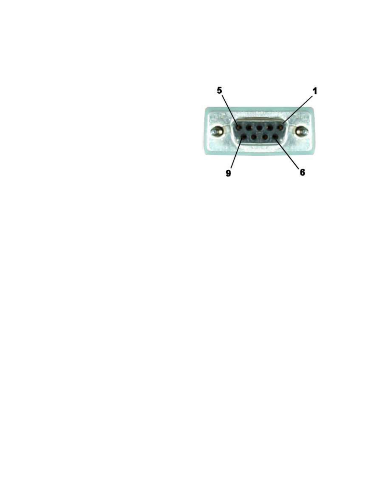
Once you have physically mounted the OAT
probe, route its attached cable to the EDCD10 remote magnetic compass module. Crimp
female pins onto the yellow and red wires, but
leave the blue wire/shield combination bare.
Plug the yellow wire into pin 2 on the female
D9 connector which mates with the EDC-D10.
Plug the red wire into pin 7. Connect the blue
wire/shield combination to the same ground
which feeds the EDC-D10 through pin 1. The
front of the female connector is pictured at right. You will be pushing the pins into the
back of this connector.
WARNING: DO NOT CONNECT WHILE THE EFIS IS
POWERED!
OAT/TAS/DA Display
Once you have uploaded the latest version of software onto your EFIS-D10 and installed
the OAT sensor, you can view data obtained from it. To display the data from the OAT
probe, bring up the menu system and navigate to the INFO menu (MORE > INFO).
Select the side of the screen that you wish to display TAS/DA information on (LEFT or
RIGHT). Push the button labeled OAT. The values for outside air temperature, density
altitude and true airspeed should display in the format seen below. Temperature is
displayed in degrees Celsius, density altitude in feet, and true airspeed in knots.
Example:
OAT 25C
09960FT
090 KTS
Calibration and Adjustment
With no calibration or adjustment, it is possible for the OAT sensor to read as much as 5
degrees Celsius off the actual value. Therefore, it may be necessary to adjust the
displayed air temperature value to compensate for this. To make this adjustment, you
must enter the menu system and proceed through the following set of button presses:
MORE > SETUP > MORE > MORE > OATADJ
8/30/2005 OAT Installation and Usage Guide page 2 of 3
Page 3

This will display the OAT adjustment menu. Now, press INC or DEC to increase or
decrease the currently displayed OAT value.
It is important to make this adjustment when the air surrounding the OAT probe is at a
known temperature. This can be achieved with a standard thermometer or another OAT
sensor on your plane. Adjust the displayed OAT until it agrees with your independent
temperature reference.
Troubleshooting
OAT value fluctuates wildly
If the OAT probe is improperly wired, the EFIS-D10 will not receive a valid signal from
it. Verify that the three wires coming from the OAT probe are wired exactly as described
in the Wiring Instructions section above.
OAT value is consistently high/low
You need to adjust the displayed OAT value to correct for sensor inaccuracies. Follow
the instructions in the Calibration and Adjustment section above.
INFO items will not allow display of OAT/TAS/DA
The menu system prevents access to the outside air temperature-based information when
either the EDC-D10 is not properly connected to the EFIS-D10 or the OAT probe is not
properly connected to the EDC-D10. First, make sure that the EDC-D10 can
communicate with the EFIS-D10 by moving a headphone speaker around near the EFISD10. If the EDC-D10 is properly connected the heading should not change. If this is the
case, the problem is with the connection of the OAT probe to the EDC-D10. Verify that
the wiring matches that described in the wiring section above.
8/30/2005 OAT Installation and Usage Guide page 3 of 3
 Loading...