

Page 1

EFIS-D10A
Installation Guide
This product is not approved for installation in type certificated aircraft
P/N 100341-000, Revision J
For use with firmware version 5.4
August, 2010
Copyright © 2003-2010 by Dynon Avionics, Inc.
Page 2

Page 3

Contact Information
Dynon Avionics, Inc.
19825 141
st
Place NE
Woodinville, WA 98072
Phone: (425) 402-0433 - 7:00 AM – 5:00 PM (Pacific Time) Monday - Friday
Fax: (425) 984-1751
Dynon Avionics offers online sales, extensive support, and continually-updated information on its products via its
Internet sites:
www.dynonavionics.com/support
docs.dynonavionics.com
– Current and archival documentation.
downloads.dynonavionics.com
support.dynonavionics.com
store.dynonavionics.com
wiki.dynonavionics.com
– Dynon’s secure online store for purchasing all Dynon products 24 hours a day.
– Dynon Avionics’ Documentation Wiki provides enhanced, extended,
–Dynon Avionics primary web site; including:
– Software downloads.
– Support resources.
continuously-updated online documentation contributed by Dynon employees and customers.
forum.dynonavionics.com
– Dynon Avionics’ Internet forum where Dynon customers can interact and
receive Dynon technical support outside of telephone support hours. A key feature of the forum is that it
allows the exchange of diagrams, photos, and other types of files.
newsletter.dynonavionics.com
blog.dynonavionics.com
– Dynon’s email newsletter.
– Dynon’s blog where you can find new and interesting Dynon-related content.
Copyright
2003-2010 Dynon Avionics, Inc. All rights reserved. No part of this manual may be reproduced, copied, transmitted, disseminated or stored in
any storage medium, for any purpose without the express written permission of Dynon Avionics. Dynon Avionics hereby grants permission to
download a single copy of this manual and of any revision to this manual onto a hard drive or other electronic storage medium to be viewed for
personal use, provided that such electronic or printed copy of this manual or revision must contain the complete text of this copyright notice and
provided further that any unauthorized commercial distribution of this manual or any revision hereto is strictly prohibited.
Information in this document is subject to change without notice. Dynon Avionics reserves the right to change or improve its products and to
make changes in the content without obligation to notify any person or organization of such changes. Visit the Dynon Avionics website
(www.dynonavionics.com
products.
) for current updates and supplemental information concerning the use and operation of this and other Dynon Avionics
Limited Warranty
Dynon Avionics warrants this product to be free from defects in materials and workmanship for three years from date of shipment. Dynon
Avionics will, at its sole option, repair or replace any components that fail in normal use. Such repairs or replacement will be made at no charge
to the customer for parts or labor. The customer is, however, responsible for any transportation cost. This warranty does not cover failures due to
abuse, misuse, accident, improper installation or unauthorized alteration or repairs.
THE WARRANTIES AND REMEDIES CONTAINED HEREIN ARE EXCLUSIVE, AND IN LIEU OF ALL OTHER WARRANTIES
EXPRES
SED OR IMPLIED, INCLUDING ANY LIABILITY ARISING UNDER WARRANTY OF MERCHANTABILITY OR FITNESS
FOR A PARTICULAR PURPOSE, STATUTORY OR OTHERWISE. THIS WARRANTY GIVES YOU SPECIFIC LEGAL RIGHTS, WHICH
MAY VARY FROM STATE TO STATE.
IN NO EVENT SHALL DYNON AVIONICS BE LIABLE FOR ANY INCIDENTAL, SPECIAL, INDIRECT OR CONSEQUENTIAL
DAMA
GES, WHETHER RESULTING FROM THE USE, MISUSE OR INABILITY TO USE THIS PRODUCT OR FROM DEFECTS IN
THE PRODUCT. SOME STATES DO NOT ALLOW THE EXCLUSION OF INCIDENTAL OR CONSEQUENTIAL DAMAGES, SO THE
ABOVE LIMITATIONS MAY NOT APPLY TO YOU.
Dynon Avionics retains the exclusive right to repair or replace the instrument or firmware or offer a full refund of the purchase price at its sole
discretion. SUCH REMEDY SHALL BE YOUR SOLE AND EXCLUSIVE REMEDY FOR ANY BREACH OF WARRANTY.
T
hese instruments are not intended for use in type certificated aircraft at this time. Dynon Avionics makes no claim as to the suitability of its
products in connection with FAR 91.205.
Dynon Avionics’ products incorporate a variety of precise, calibrated electronics. Except for replacing the optional internal backup battery in
EFIS-based products per the installation guide, our products do not contain any field/user-serviceable parts. Units that have been found to have
been taken apart may not be eligible for repair under warranty. Additionally, once a Dynon Avionics unit is opened up, it will require calibration
and verification at our Woodinville, WA offices before it can be considered airworthy.
Page 4

Page 5

Table of Contents
Contact Information......................................................................................................................................................iii
Copyright......................................................................................................................................................................iii
Limited Warranty .........................................................................................................................................................iii
1. 1-1 Introduction
OEM Installations...................................................................................................................................................... 1-1
Warning ..................................................................................................................................................................... 1-1
About this Guide........................................................................................................................................................ 1-2
Menu Descriptions..................................................................................................................................................... 1-2
2. 2-1 Wiring Overview
Recommended Wiring Practices................................................................................................................................2-1
Power Requirements.................................................................................................................................................. 2-1
25-Pin Female EFIS Harness..................................................................................................................................... 2-2
3. 3-1 Instrument Installation
Selecting a Remote Compass Module Location ........................................................................................................ 3-1
EDC-D10A Communication Cable ........................................................................................................................... 3-2
Power Inputs.............................................................................................................................................................. 3-3
Serial Communication Cable..................................................................................................................................... 3-4
SL30 and/or GPS connection..................................................................................................................................... 3-5
Altitude Encoder Wiring ........................................................................................................................................... 3-8
Audio Alert Output...................................................................................................................................................3-10
Dynon Smart Avionics Bus (DSAB) Wiring............................................................................................................3-11
Panel Location and Mounting...................................................................................................................................3-12
Connecting Static & Pitot Lines ...............................................................................................................................3-14
4. 4-1 EFIS Calibration and Configuration
Ensuring Proper Installation ...................................................................................................................................... 4-1
Setting Zero Pitch (In flight)...................................................................................................................................... 4-1
Compass Heading Calibration ................................................................................................................................... 4-1
Configure Airspeed Color Thresholds....................................................................................................................... 4-7
5. 5-1 DSAB Configuration
Network Concepts ..................................................................................................................................................... 5-1
Example Networks .................................................................................................................................................... 5-2
Initial Setup ............................................................................................................................................................... 5-4
Network Status .......................................................................................................................................................... 5-5
6. 6-1 Autopilot Installation and Configuration
Additional Information and Updates ......................................................................................................................... 6-1
DSAB Firmware Compatibility................................................................................................................................. 6-2
Compass Calibration Critical For Certain AP Modes................................................................................................ 6-2
Autopilot System Electrical Installation .................................................................................................................... 6-3
Servo Mechanical Installation ................................................................................................................................... 6-6
AP74 Mechanical Installation...................................................................................................................................6-11
Firmware Upgrades Required For AP Functionality ................................................................................................6-13
AP Servo Configuration ...........................................................................................................................................6-14
AP74 Configuration..................................................................................................................................................6-30
7. 7-1 Appendix
Appendix A: Ongoing Maintenance and Troubleshooting........................................................................................ 7-1
Appendix B: Dynon OAT Probe Installation and Usage........................................................................................... 7-7
EFIS-D10A Installation Guide v
Page 6

Table of Contents
Appendix C: HS34 Installation and Configuration...................................................................................................7-10
Appendix D: Dynon AOA/Pitot Installation and Calibration ...................................................................................7-24
Appendix E: Encoder Serial-to-Gray Code Converter Installation...........................................................................7-32
Appendix F: Replacing the EFIS-D10A battery pack ..............................................................................................7-35
Appendix G: Weights...............................................................................................................................................7-36
Appendix H: EFIS-D10A Specifications..................................................................................................................7-36
vi EFIS-D10A Installation Guide
Page 7

1. INTRODUCTION
This manual provides information about the physical, electrical, and plumbing installation of the
EFIS-D10A, EDC-D10A and optional AOA pitot probe purchased from Dynon Avionics.
Additionally, this guide deals with setting up the installation-dependant firmware options.
Because you may not have purchased all the components, you need only read through the
relevant sections of this guide. Information about the operation of this instrument can be found
in the EFIS-D10A Pilot’s User Guide.
The EFIS-D10A uses solid-state sensor technology to give an accurate and easy-to-understand
display. To ensure accuracy in its readings, it is very important that you install the instrument
correctly and perform the specified calibration steps. This installation guide will help you
through that process.
OEM Installations
If your EFIS-D10A is installed by an OEM distributor, you may find that you are unable to
access some menus and settings. Some Dynon distributors customize various areas of the EFISD10A firmware to maintain a consistent pilot experience and minimize integration issues across
a large number of installations. Currently, OEMs can customize access levels to the following
settings on Dynon systems: EMS GLOBAL setup menu, EMS SENSOR setup menu, fuel
calibration, trim calibration, flaps calibration, GPS/NAV setup menu, screen configurations, data
logging, and checklists/data panels. OEM distributors have the option of customizing some or all
of these areas. Please contact your aircraft’s manufacturer if you have any questions about how
your unit has been customized.
Warning
Dynon Avionics’ products incorporate a variety of precise, calibrated electronics. Except for
replacing the optional internal backup battery in EFIS-based products per the installation guide,
our products do not contain any field/user-serviceable parts. Units that have been found to have
been taken apart may not be eligible for repair under warranty. Additionally, once a Dynon
Avionics unit is opened up, it will require calibration and verification at our Woodinville, WA
offices before it can be considered airworthy.
EFIS-D10A Installation Guide 1-1
Page 8

Introduction
About this Guide
In the electronic (.PDF) version of this manual, page and section references in the Table of
Contents and elsewhere act as hyperlinks taking you to the relevant location in the manual. The
latest version of this manual is available on the Dynon Avionics website at
docs.dynonavionics.com.
The following icons are used in this guide:
Any text following this icon describes functionality available only with the HS34 HSI
Expansion Module connected to your system.
Any text following this icon describes functionality available only with the AP74
Autopilot Interface Module connected to your system.
Any text following this icon describes functionality that is possible when multiple Dynon
Avionics products are networked together via the Dynon Smart Avionics Bus (DSAB).
Any text following this icon refers to a setting or situation which merits particularly close
attention.
Menu Descriptions
Throughout this guide, the “>“ character is used to indicate entering a deeper level of the menu
system. For example, “EFIS > SETUP > VRSION” indicates entering the EFIS menu, pressing
MORE, then pressing SETUP, and then pressing VRSION to enter the firmware version menu.
Note that the MORE button is not shown in the sequence, since pressing MORE reveals more
options in the same level of the menu system.
1-2 EFIS-D10A Installation Guide
Page 9

2. WIRING OVERVIEW
Please follow these instructions explicitly as improper wiring can result in permanent damage to
your instrument and/or the accompanying sensors.
All electrical power and EFIS-specific lines interface with the EFIS-D10A via the female 25-pin
D-sub connector on the back of the instrument. Ensure that the unit powers on and that all
indicators display expected values before completing the final physical assembly.
Recommended Wiring Practices
For all electrical connections, use correct wiring techniques, taking care to properly
insulate any exposed wire. A short circuit between any of the wires may cause damage to
the EFIS-D10A and/or your aircraft. Make all connections to your harness before
plugging it into any of the components of the system. Do not make connections while
power is applied at any point in the system.
Dynon Avionics sells a wiring harness for all connections to the EFIS-D10A. The harness is
made up of 22 AWG wire and meet Mil Standard MIL-W-22759/16 (Tefzel insulation). If you
have opted not to purchase this harness, please refer to the provided wiring diagrams for
construction information. We recommend that all wire you use also meets Mil Standard MIL-W22759/16; all wire supplied by Dynon Avionics (with the exception of thermocouple wire, which
uses FEP insulation) meets this specification.
When using any pre-manufactured harness, verify that each pin has continuity with the expected
wire on the wiring diagram. This test can be easily done with a multimeter. When verifying
harnesses, use the wiring charts and diagrams in this guide as your ultimate authority on pin
function (for any harness) and wire color (for harnesses purchased from Dynon Avionics).
Route all wiring such that there are no spots where it could chafe or break. Use appropriate strain
relief at all junctions between wires and connectors. We recommend that you secure all wires at
regular intervals along wiring runs to accommodate vibration effects.
All connections on the EFIS female 25-pin harness are described in the Instrument Installation
section on page 3-1.
Power Requirements
22 AWG wire is normally sufficient for the power supply and ground lines, but we recommend
that you consult a wire sizing chart and determine the size required for the wire routing in your
particular aircraft. Ensure that the power lines include a circuit breaker or an appropriately sized
fuse for the wire you select. Power is fed to the EFIS-D10A via pins in the female D-25
connector as shown on the 25-Pin Female EFIS Harness diagram on page 2-2.
The EFIS-D10A system-wide power requirement is 8 watts typical and 13 watts maximum. On
a 12-volt system, this translates to about 1 amp of maximum current draw. On a 24-volt system,
this translates to about 0.5 amp maximum current draw. Normally, a 2-amp circuit breaker or
fuse is sufficient.
EFIS-D10A Installation Guide 2-1
Page 10
Wiring Overview
25-Pin Female EFIS Harness
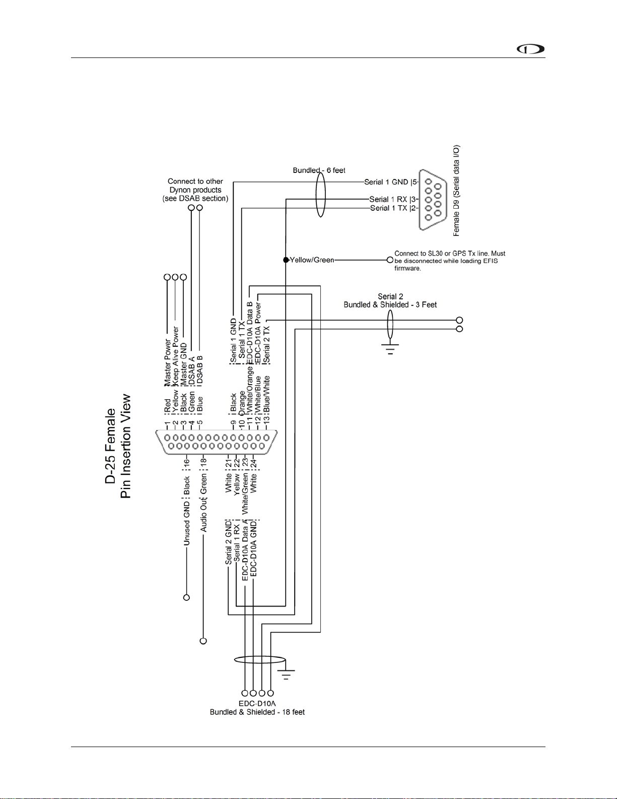
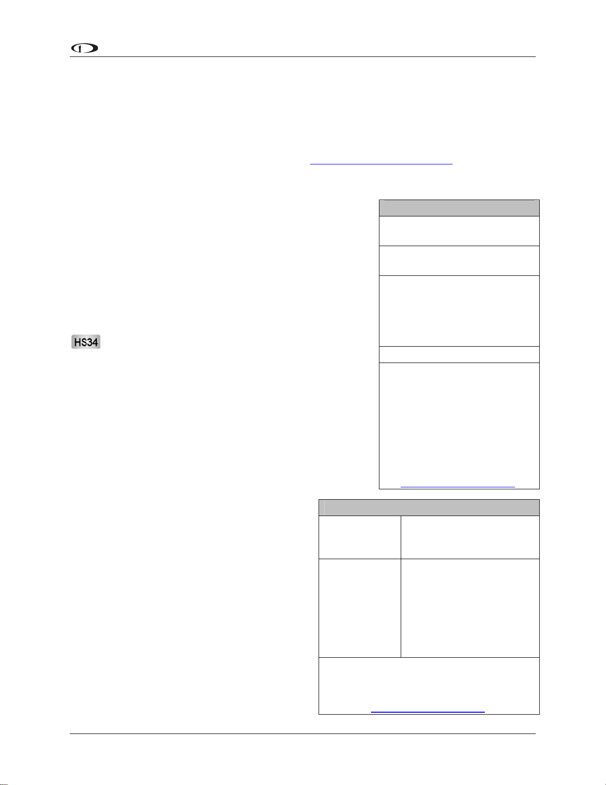
Below is the wiring diagram of the EFIS 25-pin female harness. If you purchased your harness
from Dynon Avionics, it is color coded according to the chart on the following page. Unless
noted otherwise, all wires are 3 feet long on the Dynon-provided harness.
2-2 EFIS-D10A Installation Guide
Page 11

Wiring Overview
The pin assignments for the female 25-pin harness are repeated below. Note that the pin numbers
are labeled on the face of both the female and male connector. Each connection on the harness
supplied by Dynon is color-coded. These colors are listed in the following chart.
Female
DB25
Pin #
1 Red Master Power (10-30 volts) Page 3-3
2 Yellow
3 Black Master Ground Page 3-3
4 Green DSAB-A Page 3-11
5 Blue DSAB-B Page 3-11
6 N/A No Connect
7 N/A No Connect
8 N/A No Connect
9 Black (bundled) PC Serial Ground Page 3-4
10 Orange (bundled)
11
12
13
14 N/A No Connect
15 N/A External Backup Power Page 3-3
16 Black Ground
17 N/A No Connect
18 Green Audio out Page 3-10
19 N/A No Connect
20 N/A No Connect
21
22 Yellow (Bundled)
23
24 White EDC-D10A GND Page 3-1
25 N/A No Connect
Dynon Harness Wire
Color
White/Orange (Red on some
harnesses)
White/Blue (Black on some
harnesses)
Blue/White (black on some
harnesses)
White (Bundled in Encoder
cable)
White/Green (Green on some
harnesses)
Function Details
Keep Alive Power (10-30 volts,
always on)
EFIS-D10A Transmit / PC Serial
Receive (RS-232)
EDC-D10A Data B
EDC-D10A Power (12V)
Serial Encoder Transmit (RS-232)
Serial Encoder Ground
EFIS-D10A Receive / PC Serial
Transmit (RS-232)
EDC-D10A Data A
Page 3-3
Page 3-4
Page 3-1
Page 3-1
Page 7-32
Page 7-32
Page 3-4
Page 3-1
EFIS-D10A Installation Guide 2-3
Page 12
Wiring Overview
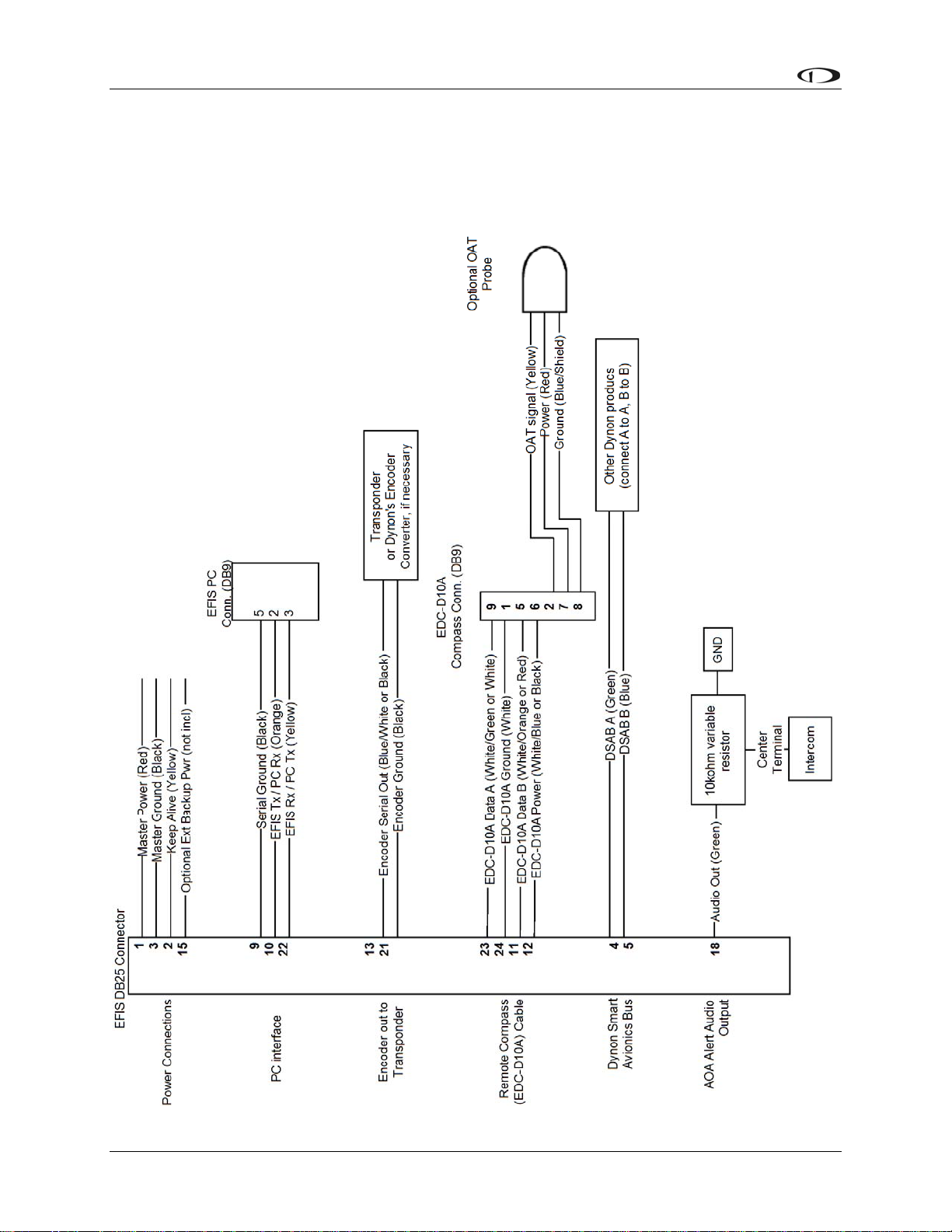
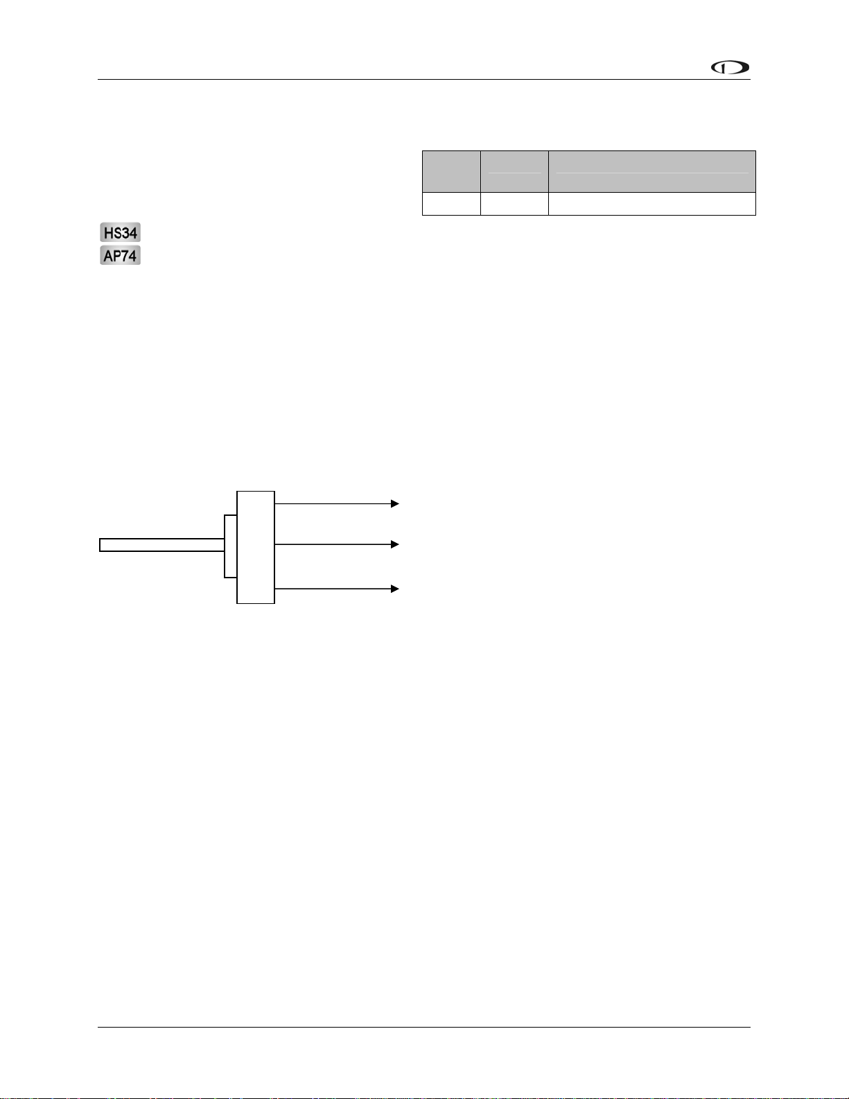
WIRING SYSTEM OVERVIEW
The following block diagram depicts the basic layout of the EFIS DB25 electrical connections
and is for reference only. Read the specific instructions for each connection prior to installation.
The colors shown refer to the Dynon-supplied EFIS harness.
2-4 EFIS-D10A Installation Guide
Page 13
3. INSTRUMENT INSTALLATION
This section provides you with the information needed to physically and electrically install the
EFIS-D10A.
Selecting a Remote Compass Module Location
Finding a good location for the EDC-D10A
remote compass module is critical to an
accurate EFIS-D10A heading display. Keep
in mind that calibration can compensate for
small static magnetic fields superimposed
upon the earth’s field; it cannot take
into account dynamic effects like
AC currents, non-constant DC
currents and non-stationary ferrous
material (e.g., an electric turn
coordinator). Use the following
suggestions to help you find a good
location for your EDC-D10A.
Keep the EDC-D10A away
from any source of magnetic fields (such
as electrical equipment and currentcarrying wires) and ferrous material.
Move a handheld compass throughout the
space surrounding your location to get a
rough idea of the suitability of your
chosen location. If the needle deviates
significantly from magnetic north in any
given area, that location would not be
ideal for the EDC-D10A.
The EDC-D10A can be mo unted
anywhere in the aircraft (away from
magnetic interference) such that its pitch
is as close to that of the EFIS-D10A as
possible. It does not need to be
directly along any axis of the EFISD10A. It should be mounted with the
long axis parallel to the wings, the
electrical connector facing toward the
front of the plane, and the mounting
tabs on the bottom. The bracket used
to hold the EDC-D10A must hold th
EDC-D10A at the same pitch, roll,
and yaw as the EFIS-D10A with
EFIS-D10A Installation Guide 3-1
e
Side view of EDC-D10A, tabs mounted
down and aligned within 1 degree of pitch
Connector forward and
tabs mounted down
with EFIS-D10A
Connector toward
direction of flight
Page 14
Instrument Installation
respect to the airframe. We recommend that you use an electronic level, if available, t
make sure the EDC-D10A is alignedo with the EFIS-D10A to better than 1 degree.
All mounting hardware needs to be made from non-ferrous material such as aluminum,
plastic, or brass. Many stainless steel screws are magnetic. If the item is attracted to a
magnet, it should not be used in the installation. The EDC-D10A needs to be mounted in
a location as free from magnetic interference as possible. This means keeping the EDCD10A away from any ferrous nuts, bolts, and screws, aircraft tubing, as well as from
wires or devices carrying any appreciable current such as strobe light wiring, autopilot
servos, or other electronics.
EDC-D10A Communication Cable
DO NOT ATTEMPT TO POWER UP THE EFIS-D10A WITH THE EDC CABLE
LEADS EXPOSED (UNSHEATHED) AND NOT INSTALLED IN THE DB9
CONNECTOR. SHORTING THESE CONNECTIONS WILL CAUSE DAMAGE TO
THE UNIT.
Like the RS-232 PC Communication cable, the EDC-D10A communications cable terminates in
a standard female DB9 connector. While they look similar, do not plug the EDC cable into a PC
or vice versa. The following table outlines the four connections that must be made to ensure
proper communication between the EFIS-D10A and the EDC-D10A remote compass module.
The Dynon-supplied harness colors are listed, as well.
EFIS
DB25 pin#
11 5 EDC Data B White/Orange (or Red)
12 6 EDC Power White/Blue (or Black)
23 9 EDC Data A White/Green (or Green)
24 1 EDC Ground White
The EDC cable in the harness supplied by Dynon consists of 4 conductors, surrounded by a
metal shield and white insulation. These 4 wires are terminated with crimped female D-sub pins
wrapped in plastic tubing. If you are building your own cable, we recommend that you use
shielded cable as well.
With the 25-pin EFIS harness disconnected from the EFIS-D10A, carefully cut or pull the
tubing off the 4 D-sub pins.
Route the cable to the EDC-D10A mounting location chosen according to the instructions
above.
Install the female pins in the correct holes on the included DB9 connector, according to
the chart above. Note that Dynon has shipped harnesses with different colors for the
EDC cable; determine your connections using the two sets of colors in the table above.
Install the back shell around the DB9 connector.
Correct wiring installation can be easily verified once completed. Power on the EFIS-D10A with
the EDC-D10A connected to it. Observe the displayed heading and then hold one of the
earpieces of a headset near the front of the EFIS-D10A. If the EDC-D10A is correctly wired, you
should see no change in the displayed heading when the headset earpiece and its magnetic
EDC
DB9 pin# Function Wire color
3-2 EFIS-D10A Installation Guide
Page 15

Instrument Installation
speaker is near the EFIS-D10A. If you see a substantial change in heading, there is a
communication problem between the EFIS-D10A and the EDC-D10A.
The metal shield around the EDC communication cable is connected to the short black/white
wire emanating from the DB25. Connect this wire to ground close to the EFIS-D10A, ideally the
panel.
Power Inputs
The EFIS-D10A has three separate power inputs, located on the DB25 EFIS connector. Of the
three, only Master Power is required to operate the instrument. The other two inputs provide
redundancy. Below is a table that explains the three inputs and their purposes. All three of these
inputs share a common ground signal, wired to pin 3 on the EFIS connector.
EFIS
DB25
pin#
1 Master
2 Keep Alive
3 Master
15 External
Function EFIS DB25
Power
Power
Ground
Backup
Power
Description
wire color
Red Provides primary power to the instrument. The
EFIS-D10A will switch on upon application of
power. Connect to a switched power source. Will
not be adversely affected by engine cranking.
Yellow A very low current power input which is only
used if both Master and External Backup Power
are not applied. Keep Alive draws just enough
current to keep the clock running. It draws less
than 1 milliamp of current when not charging the
internal backup battery.
Dynon Avionics recommends not connecting the
Keep Alive wire when the EFIS-D10A has an
internal battery installed or is connected to a GPS.
Keep Alive is only used in installations with no
battery or GPS to keep the clock running when
the unit is powered off.
Black Connect to ground. Must carry as much as 2
amps.
(Not wired in
Dynon
harness)
Will operate the EFIS-D10A only if Master
Power is not present. The transition from Master
Power to External Backup Power will bring up a
warning, requiring you to press ACK within 30
seconds to keep the unit operating. This warning
will also display when transitioning from either
Master or External Backup to Internal Battery
power.
EFIS-D10A Installation Guide 3-3
Page 16

Instrument Installation
Serial Communication Cable
More Information Is Available Online: Serial communication to non-Dynon devices,
and interfacing of other devices in general can be involved and detailed. This Installation
Guide is intended to provide general installation advice for the most common devices and
situations. Dynon’s Documentation Wiki provides enhanced, extended, frequently
updated online documentation contributed by Dynon employees and customers at
wiki.dynonavionics.com.
The EFIS-D10A has one RS-232 serial port that can be used for several purposes. This serial
port can only be configured for one purpose at a time.
The EFIS Serial port (DB25) is used for:
Connecting to a PC, and using the Dynon Avionics Product Support Program to perform
firmware upgrades, configure checklists, and download internal logs. The Help Files of
the Support Program provide detailed instructions on these functions. The latest version
of the Product Support Program is available on the Dynon web site at
downloads.dynonavionics.com.
Connecting serial devices such as a GPS receiver or an SL30.
“Streaming” real-time EFIS flight data to an external serial device for recording. For data
formats and other information, see the Appendix in the EFIS-D10A Pilot’s User Guide.
Note that for the purposes of logging data, version 5.0 of EFIS-D10A firmware added
internal data logging and retrieval via the Dynon Product Support Program.
When an optional HS34 Expansion Module is connected to your Dynon DSAB network,
all GPS and NAV radios must be connected to it. This simplifies the connection and
usage of multiple serial devices. The HS34 also provides interfaces to non-serial devices
such as those with only analog and ARINC-429 interfaces.
PC USB CONNECTION
If you do not have a serial port on your PC, you may use a USB-to-Serial adapter to connect the
EFIS-D10A to your PC’s USB port. You may purchase an adapter from us, Radio Shack, or
many computer stores. If you are using Windows 2000 or XP, ensure that the adapter driver CD
is inserted in your PC before plugging the adapter into the USB port for the first time. If you are
using Windows Vista, ensure that you are connected to the Internet and do not use the driver
CD; the operating system will download the correct driver. Also, do not have your EFIS-D10A
plugged into the USB-to-Serial adapter while installing the driver.
EFIS SERIAL HARNESS
On the EFIS 25-pin wiring harness
available from Dynon, there are three
wires bundled together, terminating in a
standard DB9-pin female connector. This
cable is 6’ long and pre-assembled for
connection to a PC-based laptop. Route
this cable to a convenient location that can
EFIS
DB25
Pin#
9 5 Black Signal ground
10 2 Orange EFIS-D10A transmit /
22 3 Yellow EFIS-D10A receive /
DB9
Pin#
Wire
Color
RS-232 Function
device receive
device transmit
3-4 EFIS-D10A Installation Guide
Page 17
Instrument Installation
be accessed whenever you need to update your product’s firmware or checklists.
If you did not purchase a harness from Dynon, obtain a 9-pin D-sub connector and make the
three connections shown in the table.
To verify proper communication between the EFIS-D10A and the PC, use the Dynon Avionics
Product Support Program’s “Detect Firmware Version” function. Download the latest version of
the Support Program from the Dynon Web Site at download.dynonavionics.com.
SL30 and/or GPS connection
Depending on the number and types of Dynon units you own,
you have several options for connecting a GPS unit and/or
Garmin/Apollo SL30 to your Dynon system. The GPS can be
used as a data source for the EFIS, HSI, and Fuel pages, as
well as Dynon’s EFIS-based Autopilot. The SL30 can be
used as a VOR, localizer, or ILS (localizer + glideslope)
source for the HSI. If you wish to connect a GPS and/or
SL30 to your Dynon system, read the section below which
corresponds to your set of Dynon products.
If your system has an HS34, it is required that all
GPS and NAV devices are connected to the HS34.
The EFIS-D10A does not support directly connected
GPS and NAV devices when an HS34 is installed in
the system. Refer to the HS34 Installation and
Configuration section on page 7-10 for device
connection details.
To use the GPS-related features on your EFIS and/or EMS,
your GPS must output either “aviation format” or the
following NMEA sentences in its serial stream: $GPRMC,
$GPRMB, $GPGGA, and one of $GPBOD or
$GPAPB. You must also have a supported cable
that exposes your GPS’s serial transmit line. If
you own a Garmin 430 or 530, in the
UNITS/MAGVAR option, set the MAGVAR to
AUTO. The EFIS-D10A auto-detects most
GPSs, but may require a manual setting for
some. This is true for communication with at
least the Garmin 480 and maybe others such as
the GX50, and GX60, and Bendix/King Skymap
IIIc. From the EFIS menu, enter SETUP >HSI
>EFIS_SERIAL; from the EMS menu enter
SETUP >GLOBAL >EMS SERIAL. In that
menu select the INPUT to be AVIATION and
the BAUD RATE to be 9600.
GPS units with limited functionality
AnywhereMap Does not output all needed
Garmin
(Apollo) GNS
480
A frequently updated list of compatible GPS
units and settings is available at our
GPS units known to work
AvMap EKP-IV (v2.06.116R,
NMEA set to “processed”)
Bendix/King Skymap (set to
AR NAV 9600 output)
Garmin
96, 96c, 150XL, 195, 196, 295,
296, 396, 400*, 420*, 430*,
430W*, 496, 500*, 520*,
530*, 530W*, GX60, GX65
Lowrance handhelds
* Do not output time over
serial; ARINC connection via
HS34 required to receive time.
A frequently updated list of
compatible GPS units and
settings is available at our
Documentation Wiki at
wiki.dynonavionics.com.
sentences. Time output is
wrong.
Possibly works with latest
Dynon product firmware,
but untested. Requires
manual configuration. See
note at left. Fully
compatible via ARINC
into optional HS34.
Documentation Wiki at
wiki.dynonavionics.com.
EFIS-D10A Installation Guide 3-5
Page 18

Instrument Installation
The following connection schemes assume that the external devices share a common ground
with the Dynon product(s). If your GPS is battery powered, and not normally connected to
aircraft ground, you must connect the ground pin on its serial output to a ground common to the
EFIS-D10A.
When a Dynon product is connected to a GPS, it will synchronize its Zulu clock to the time
reported by the GPS. However, some GPSs, such as the Garmin 430 and 530, do not report time
in their serial output stream. Dynon products have no way to synchronize to these GPSs’ clocks.
Read the section below that corresponds to your configuration of Dynon products. All EFISbased product configurations direct you to connect your external device to PC serial receive (pin
22) on your Dynon EFIS product. You may make this connection at any point between pin 22 on
the EFIS DB25 and pin 3 on the connected DB9 EFIS/PC connector. If you purchased your
harness from Dynon Avionics, it may have a yellow/green wire provided for this purpose.
IF YOU OWN ONLY AN EFIS-D10A OR EFIS-D100
Connect the GPS or SL30 transmit line into pin 22 on the DB25 connector. This is the same
Serial Rx line that is used for firmware updates. You will need a way to disconnect this when
you plug your EFIS into a PC for firmware updates and checklists.
If you have both a GPS unit and an SL30, you will need to wire the two transmit lines to a 3-way
switch; connect the output of the switch into pin 22 on the EFIS harness. You will use this switch
to toggle between GPS, SL30 and a disconnected state. The HSI auto-detects the switched
instrument and will change modes automatically.
IF YOU OWN TWO EFIS-ONLY UNITS
When 2 EFIS-only units are connected via DSAB, only the DSAB Bus Master’s serial port is
active.
If you have only one serial device (GPS or SL30), connect its transmit line to pin 22 on the
DB25 connector of the EFIS that you have chosen to be the Bus Master. This is the same Serial
Rx line that is used for firmware updates. You will need a way to disconnect this when you plug
your EFIS into a PC for firmware updates and checklists.
If you have both a GPS unit and an SL30, you have two options:
Wire the 2 devices’ transmit lines to a switch, allowing you to select the serial device active
on the HSI screen.
Do not connect the two EFIS units together via DSAB. You may then wire one device to one
EFIS’ pin 22, and the other device to the other EFIS. Of course, the EFIS devices would be
independent and unable to share GPS or SL30 data.
You will need a way to disconnect both lines when you plug your EFIS into a PC for firmware
updates and checklists.
IF YOU OWN ONLY AN EMS-D10 OR EMS-D120
We recommend that you only connect a GPS to an EMS-only system; without the magnetic
heading from an EFIS, the HSI page will not be functional. Connect the GPS transmit line to pin
19 on the EMS DB37 connector. This connection will give you fuel endurance information
3-6 EFIS-D10A Installation Guide
Page 19

Instrument Installation
(range, MPG, etc) on the fuel page and GPS information only (track, ground-speed, course, etc)
on the HSI page. There is no need to break this connection when doing PC updates.
IF YOU OWN AN EMS AND AN EFIS (NOT FLIGHTDEK-D180)
First, ensure that your EMS and EFIS are connected as described in Dynon Smart Avionics Bus
(DSAB) Wiring on page 3-11.
If you only have either the GPS or SL30 (but not both), connect the GPS or SL30 transm
it line to
pin 19 on the EMS DB37 connector. This is labeled “Aux Serial Receive.” With either a GPS or
an SL30 connected, you are able to display an HSI on either product; with a GPS connected, you
are able to display EMS fuel economy displays.
If you have a GPS and an SL30, connect the GPS to pin 19 on the EMS DB37 connector.
Connect the SL30 to pin 22 on the EFIS DB25 connector. This will allow you to flip between
GPS and SL30 inputs. You can use either the SL30 or GPS as the NAV source on the EFIS
product. You will need to disconnect the SL30 from the EFIS when doing software updates.
IF YOU OWN ONLY A FLIGHTDEK-D180
Connect the SL30 unit to pin 22 on the EFIS DB25 connector, and the GPS to pin 19 on the
EMS DB37 connector. You can display either source on the HSI using the softkeys. You will
need to disconnect the SL30 from the EFIS when doing software updates.
IF YOU OWN A FLIGHTDEK-D180 AND AN EFIS
Connect the SL30 unit to pin 22 on the FlightDEK’s EFIS connector (vertical DB25) and the
GPS to pin 19 on the EMS DB37 connector. You can display either source on the HSI, and you
can display either on the standalone EFIS as well (provided you have connected the DSAB A &
B lines from the FlightDEK-D180 to the standalone EFIS product). You will need to disconnect
the SL30 from the FlightDEK-D180 when doing software updates.
Do not connect any serial devices to the secondary EFIS device. It will only display data from
the serial devices connected to the master FlightDEK-D180.
EFIS-D10A Installation Guide 3-7
Page 20
Instrument Installation
Altitude Encoder Wiring
The EFIS-D10A outputs its altitude
measurements in one of four standard serial
outputs and is readable by many modern
transponders. The EFIS-D10A will function
properly whether or not this altitude encoder
functionality is used. To use the EFISD10A‘s altitude encoder functionality,
simply wire the 2 encoder connections
(GND and Encoder Transmit) from the
DB25 connector to their respective connections on
your transponder.
Per ATC/FAA requirements, the serial encoder output
of the EFIS-D10A reports pressure altitude, which, by
definition, is indicated altitude when the baro is set to
29.92. So, when you set your EFIS-D10A‘s baro
adjustment to 29.92, its indicated altitude will match
the altitude that is being reported to your transponder.
If your transponder requires parallel Gray
code input, and you wish to use the EFISD10A as your altitude encoder, you will need
to purchase Dynon Avionics’ Encoder Serialto-Parallel Converter. Please refer to page 732 for more information on the installation of
this option.
EFIS
DB25
pin# Function Wire color
Encoder
13
21 Ground White
serial
transmit
Blue/White
(or black)
There are four different serial formats used by
transponders. The EFIS-D10A can output any of these formats. To select which format the EFISD10A sends out its serial encoder output port, you must choose the appropriate format via the
menu system. When the menu system is displayed, enter the MORE > SETUP > MORE >
ALTENC. When in the Altitude Encoder Setup menu, you can toggle the resolution of the output
between 10 and 100 feet; this accommodates some transponders which can input and display
altitude in 10 foot increments. In this menu, you can also select between the four different output
formats, which are described below.
Dynon’s supplied EFIS harness has a serial altitude encoder cable which consists of 2
conductors, surrounded by a metal shield and white insulation. Dynon has shipped harnesses
with different colors for Encoder serial transmit line. Determine your connections using the table
at right. Connect the Encoder serial transmit to your transponder’s serial input or to Dynon’s
Serial-to-Parallel Converter as described in the Encoder Serial-to-Gray Code Converter
llation section on page 7-32 in the Appendix.
Insta
3-8 EFIS-D10A Installation Guide
Page 21

Instrument Installation
SERIAL ALTITUDE FORMATS
There are four formats used by serial transponders. Choose the correct format for your
transponder in the ALTENC menu, using the FRMAT button.
Format 1
Used By
Baud rate
Format
Example message
Format 2
Used By
Baud rate
Format
Example message
Format 3
Used By
Baud rate
Format
Example message
Dynon Encoder Serial-to-Parallel Converter, Garmin AT
(formerly UPS Aviation Technologies)
1200
#AL, space, +/-sign, five altitude bytes, T+25, checksum,
carriage return
#AL +05200T+25D7[CR]
Magellan
1200
$MGL, +/- sign, five altitude digits, T+25, checksum, carriage
return
$MGL+05200T+25E3[CR]
Northstar, Garmin
2400
ALT, space, five altitude bytes, carriage return
ALT 05200[CR]
Format 4
Used By
Baud rate
Format
Example message
Garmin GTX330 (set on Icarus input), Garmin GTX327 (set
on Icarus input), Garmin GTX328, Icarus, Trimble
9600
ALT, space, five altitude bytes, carriage return
ALT 05200[CR]
EFIS-D10A Installation Guide 3-9
Page 22
Instrument Installation
Audio Alert Output
The EFIS-D10A has an audio alert output for
sounding AOA and altitude alarms through
an intercom or audio panel.
DB25
pin#
18 Green EFIS Audio Alert Output
Color Function
If you have purchased and installed an HS34 and/or an AP74, we recommend that you
only connect the HS34 audio output or AP74 audio output (but not both) to your audio
panel. The HS34 or AP74 audio output provides voice and tone outputs for both EMSand EFIS-related alerts. When the HS34 or AP74 audio output is connected, it is not
necessary to connect the audio outputs of other Dynon Avionics devices. Connecting the
HS34 audio output and the AP74 audio output in parallel will result in distorted audio.
Refer to the HS34 Wiring section on page 7-10 for more information.
Connect the alarm output from the EFIS-D10A to the outside terminal of a 10 kΩ variable
resistor (not included). Ensure that audio outputs are connected similar to the following diagram.
The 10 kΩ variable resistor can be obtained from Radio Shack (P/N 271-1715) or other
electronics suppliers.
Outside terminal
Center terminal
Outside terminal
To EFIS-D10A Audio
Alert Out
To intercom/audio
panel auxiliary input.
To ground
To set the volume of the AOA alarm, you will need your EFIS-D10A powered on and the alarm
output wired as described above. Enter the EFIS menu by pressing any button (except the
leftmost or rightmost) beneath an EFIS page. Press MORE > SETUP > MORE > MORE >
MORE > AOAALM. In that menu, press the TEST button. While the button is held down, the
AOA alarm will sound. Adjust the variable resistor until the volume in the intercom or audio
panel is at an acceptable level.
3-10 EFIS-D10A Installation Guide
Page 23
Instrument Installation
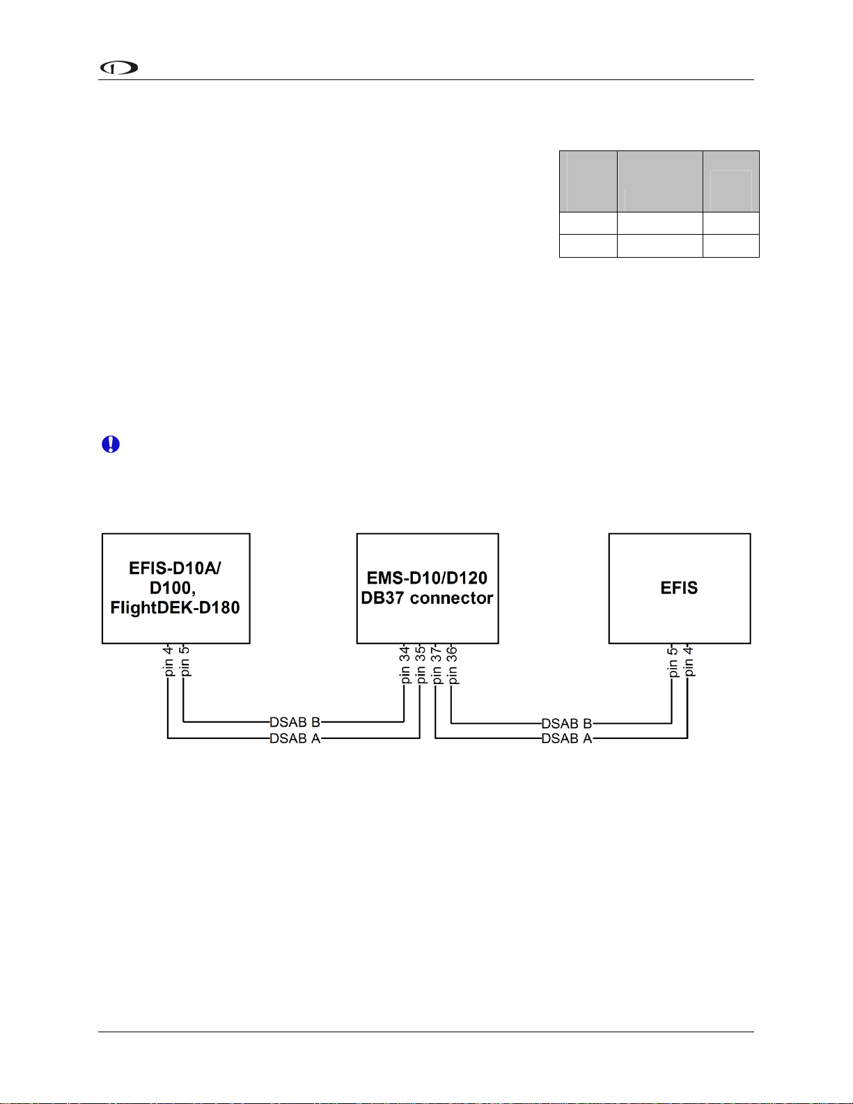
Dynon Smart Avionics Bus (DSAB) Wiring
The Dynon Smart Avionics Bus is the only way Dynon
products can communicate with one another, providing features
such as data sharing and alarm notification. DSAB is a multidrop bus, meaning several devices can be connected to the same
2 wires. If you have an EMS and EFIS product connected via
their serial ports through a null modem, you should disconnect
this legacy interface.
You must connect the DSAB A connection (pin 4) on the EFIS DB25 female harness to the
DSAB A connection for the next device in the chain. Do likewise for the DSAB B connection
(pin 5). Some products – like the EFIS series and the HS34 – have only one pair of DSAB
connections on the back connector; other products – like the EMS series – have two pairs, for
wiring convenience. If you have 3 or more devices in your system, and one of them is an EMSseries product, we recommend that you locate it in the middle of your wiring scheme as shown
below. This eliminates the need to splice two wires together.
EFIS
DB25
pin#
Function
4 DSAB-A Green
5 DSAB-B Blue
Wire
color
Wherever possible, ensure that the two DSAB wires (DSAB A and B) are run as a
twisted pair. This minimizes the system’s susceptibility to electrical noise.
Refer to the DSAB Configuration chapter on page 5-1 for detailed instructions on configuring
your DSAB network.
EFIS-D10A Installation Guide
3-11
Page 24
Instrument Installation
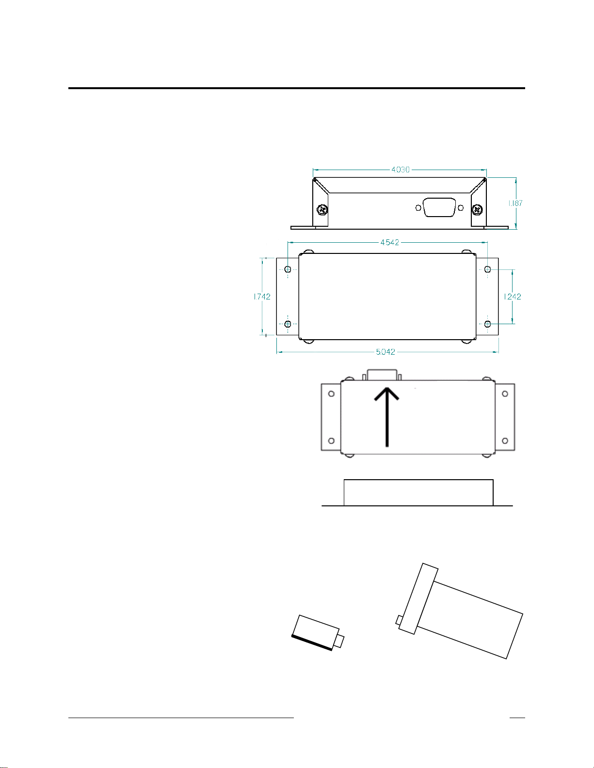
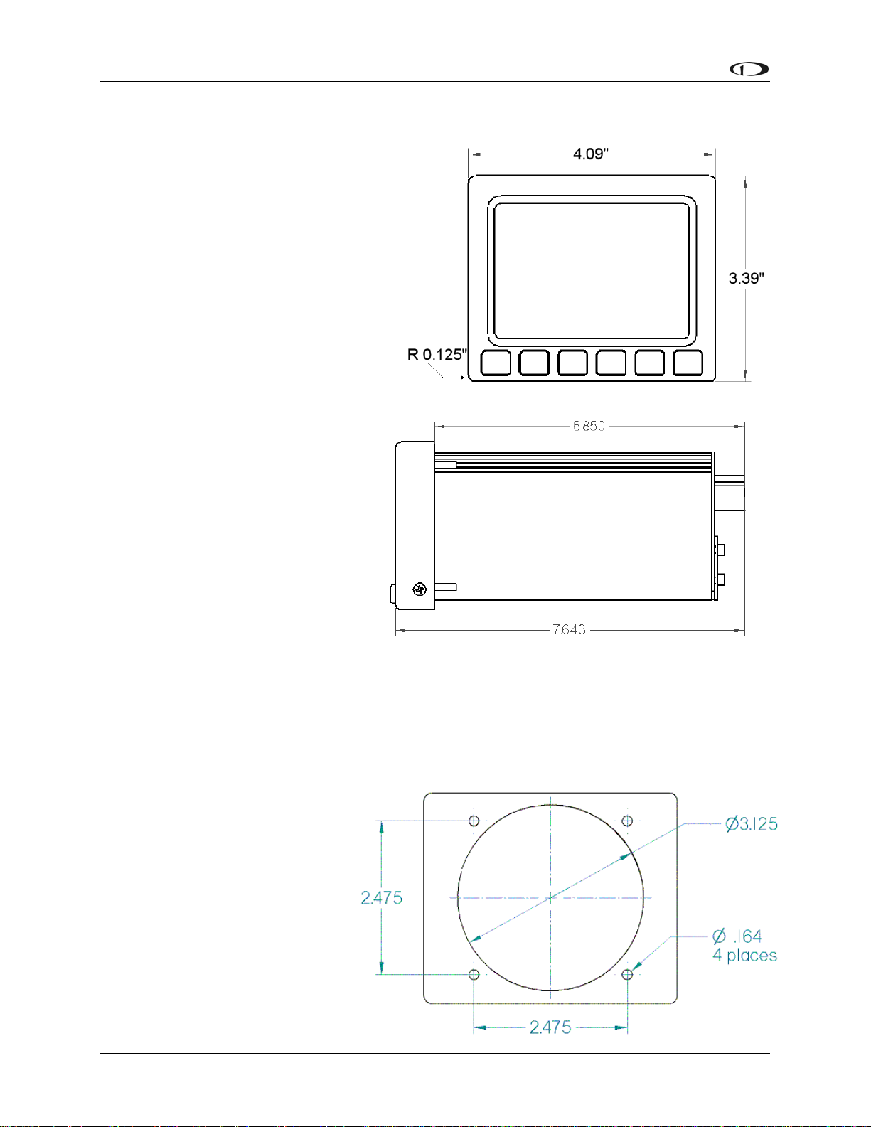
Panel Location and Mounting
The diagram at right shows the outside
dimensions of the front bezel of the EFISD10A. Note that the instrument is about
seven inches deep and the supplied
harness extends three inches more. Use
the dimensions (in inches) found on the
diagram to plan for the space required by
the instrument. Take the following
considerations into account when s
a mounting location for the EFIS-D10
electing
A.
Avoid placing
the instrument near heater
vents or any source of extremely hot or
cold air. Keep in mind that the air
surrounding the EFIS-D10A during
operation may be no warmer than 50
C to ensure accurate operation. Plan a
panel location that allows convenient
viewing of the instrument with no
obstruction. When flying straight an
d
level, the panel angle from vertical
may not be greater than +/- 30
degrees. The unit must also be p
arallel
to the roll axis of the aircraft (although
not necessarily located along it), and
have no significant roll angle in the
panel. The firmware supports an adju
stm
ent for panel tilt, but not for mounting errors in yaw or
roll. Correct attitude performance depends on mounting the EFIS-D10A square with the
direction of flight.
You have two optio
ns for mounting the EFIS-D10A into your panel: standard or flush. You may
use the optional flush-mount bracket, allowing the face of the EFIS-D10A to be flush with your
panel. If you opted to receive the
flush mount bracket, please skip to
Option 2 below. If you opted not
to receive this bracket and wish to
perform the standard install,
follow the options in Option 1
below.
OPTION 1: NO MOUNTING
BRA
CKET
U e
sing this option, you will b
mounting the EFIS-D10A direc
tly
into your panel. The front bezel of
3-12 EFIS-D10A Installation Guide
Page 25
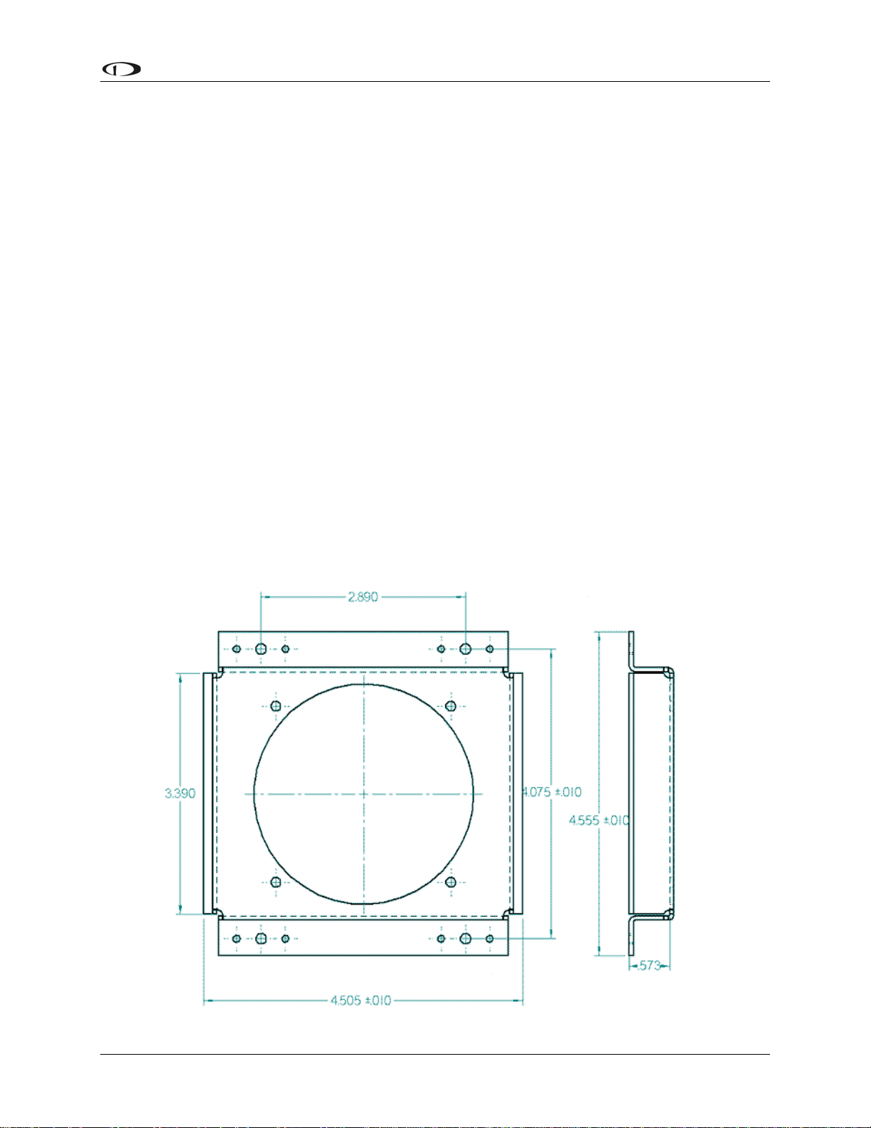
Instrument Installation
the unit will extend beyond the plane of your panel by 0.8”.
Installation of the EFIS-D10A main unit should only be completed once all other physical and
electrical installations have been performed. This will ensure that last-minute adjustments will
not have to be made with the EFIS-D10A mounted in the panel.
The diagram above shows the dimensions expected for the proper installation of the EFIS-D10A
into your panel using no mounting bracket. All units are in inches. Push the EFIS-D10A through
the main panel hole. The four studs on the back of the EFIS-D10A will fit into the four mounting
holes having dimensions listed in the diagram. Place one of the four supplied washers on each
stud before pushing the EFIS-D10A into place in the panel, putting the washers in between the
EFIS-D10A and the panel. Place one of the 4 supplied mounting nuts on the end of each of the 4
studs protruding from the back of the panel. Secure the nuts tightly against the panel to complete
the installation.
OPTION 2: FLUSH-MOUNT BRACKET
Make a rectangular cutout in your panel, ensuring that it allows the front panel of the EFISD10A to fit. The cutout required should have the dimensions 4.09” wide by 3.39” tall with
corner radii of 0.125”. You also need to drill four 0.164” holes in your panel at the four locations
shown on the diagram below (two above and two below the rectangular cutout). Install #6 plate
nuts on the back side of the bracket. Place one of the supplied washers onto each of the four
mounting studs on the EFIS-D10A and then slide the flush mount bracket over the EFIS-D10A.
The bracket should wrap around the bezel of the EFIS-D10A. Place one of the 4 supplied nuts on
each of the 4 studs and tighten the nuts. The EFIS-D10A/bracket can now be installed from
behind your panel using the #6 screws through the previously drilled holes.
EFIS-D10A Installation Guide 3-13
Page 26
Instrument Installation
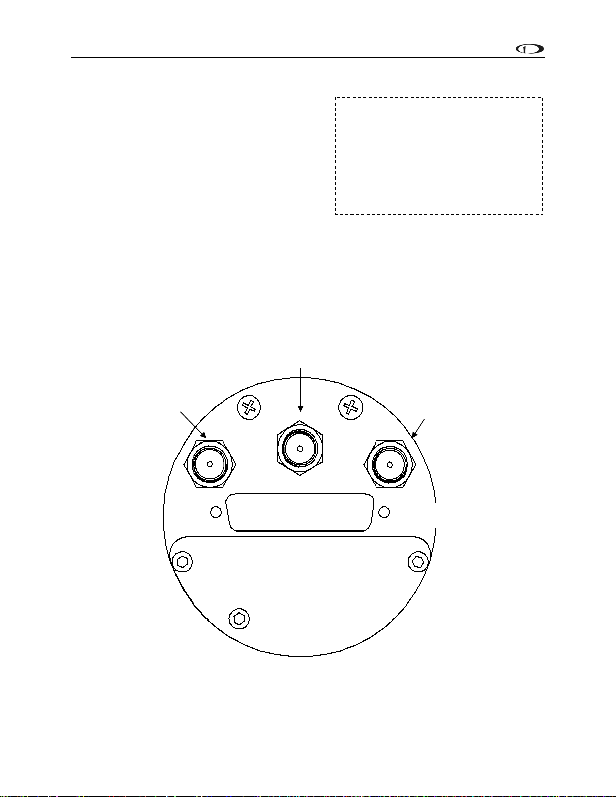
Connecting Static & Pitot Lines
The AOA, pitot, and static ports on the back of the
EFIS-D10A are equipped with 1/8” NPT Female
fittings. To attach your pitot and static lines to the
back of the EFIS-D10A, you must use standard 1/8”
NPT Male fittings at the end of each of the lines.
To install, simply connect your static and pitot
sources to the EFIS-D10A, T’ing off of existing
lines if performing a retrofit. View the following
back view diagram the placement of your pressure
lines.
Use two wrenches to both hold the brass fitting on the EFIS-D10A and secure the mating
pressure line fittings to the corresponding locations on the back of the EFIS-D10A. Do not over-
tighten or allow the brass fittings to rotate.
If you purchased Dynon’s AOA pitot tube, note that it has pitot and AOA ports on it, but not
static. You will need to provide your own source of static pressure for the EFIS-D10A and any
other instrument in your panel which requires it.
The EFIS-D10A’s attitude calculation
requires either airspeed (from pitot
and static) or GPS data. To ensure
proper operation, at least one of these
data sources must be available. We
recommend the EFIS-D10A be
connected to pitot and static systems
in all installations.
Pitot
AOA
Stati
Static
3-14 EFIS-D10A Installation Guide
Page 27

4. EFIS CALIBRATION AND CONFIGURATION
During manufacture, your EFIS-D10A underwent a comprehensive calibration, verification, and
burn-in routine that minimizes setup time and ensures that your EFIS meets Dynon’s stringent
performance specifications. To account for your individual preferences and your aircraft’s
particular setup, there are a few simple calibration and configuration steps that you must
complete before using your EFIS-D10A. This section takes you through these steps to make sure
that you have properly installed and configured your EFIS-D10A.
It is your responsibility to fly your plane safely while performing any configuration or
calibration in flight. The best scenario would include a second person to perform any
necessary steps on the unit.
Ensuring Proper Installation
Turn your unit on by energizing the aircraft power to which it is connected. Ensure that the
screen is bright and readable and that all instrument displays appear. If a desired display item is
not present, refer to the User’s Guide to use the CLUTTR feature to display the missing item.
Setting Zero Pitch (In flight)
For the purposes of this setting, level is defined as the attitude at which the aircraft’s
longitudinal axis is parallel to the ground. For most aircraft, the attitude the aircraft
assumes at normal cruise speeds will be acceptable. Additionally, this feature should not
be used to “zero out” pitch when the aircraft is at an attitude other than level. Do not
think of this adjustment as you would the parallax adjustment on a normal attitude
indicator. Instead, think of it as a calibration step which is not changed often.
With your aircraft flying straight and level, enter the EFIS > SETUP > PITCH menu. Press INC
or DEC until the horizon line intersects the center of the crosshairs. It is important that this be
done while the aircraft is level to ensure proper pitch and roll display throughout all maneuvers.
Compass Heading Calibration
This section guides you through the calibration and configuration of your magnetic heading
indication. Prior to calibrating your EFIS-D10A’s internal sensors or remote EDC-D10A, you
must configure the local magnetic inclination and magnetic intensity as described in the sections
below.
In a DSAB network, the Bus Master’s heading is used as the only heading source for all
connected instruments. However, in the event of a DSAB failure, EFIS instruments revert
to their local heading source. In a system already using a shared heading, you may still
configure and calibrate the local heading source. As soon as you bring up any of the
magnetic calibration menus (MAGINC, MAGCAL, MAGADJ, MAGINT), the heading
and DG displays switch to display the locally-derived heading indication. The display
stays on that source until exiting the magnetic configuration menu. If you do not have an
EDC-D10A connected, REMOTE COMPASS NOT DETECTED is displayed when in
any of these menus.
EFIS-D10A Installation Guide 4-1
Page 28

EFIS Calibration and Configuration
SETTING MAGNETIC INCLINATION ANGLE AND INTENSITY (REQUIRED)
To calibrate your EFIS-D10A heading, you must input your location’s current magnetic
inclination angle and intensity. Before doing this, you must obtain these two values for
the geographic location where you will be performing the calibration. Note that this
procedure only needs to be done once, prior to magnetic calibration. Moving the aircraft
to another location does not require repeating this procedure.
Obtaining Magnetic Inclination and Intensity
1. Browse to web page: www.dynonavionics.com/docs/maginfo.html. (Looking up this
information does not have to be done on a computer at the plane, with live Internet
access.)
2. The Dynon Avionics “Magnetic Inclination and Intensity” web page is updated as
needed; it contains a link to a NOAA web pages and instructions for easily finding your
local magnetic inclination and intensity by inputting your ZIP code (in the US) or your
latitude and longitude and inputting the resulting data into your Dynon EFIS.
3. Follow the instructions listed on the web page, especially clicking the “Compute
Magnetic Field Values” button at the bottom of the linked page – the values required by
your Dynon EFIS will be displayed only after clicking that button. If you are near the
equator or in the southern hemisphere, note that the inclination may be negative number.
Entering inclination and intensity into the EFIS-D10A
1. Enter the inclination setup menu by pressing any button beneath an EFIS page (except the
far left or far right hotkeys), then MORE > SETUP > MORE > MORE > MAGINC
2. Press INC or DEC to increment or decrement the displayed inclination angle. Press and
hold to change values more rapidly.
3. When the display shows the magnetic inclination angle for your location, press BACK to
leave the menu.
4. Enter the magnetic intensity setup menu by pressing any button beneath an EFIS page
(except the far left or far right hotkeys), then MORE > SETUP > MORE > MORE >
MAGINT
5. Press SEL to change the digit being incremented or decremented. Press INC or DEC to
increment or decrement the selected digit. Press and hold to change values more rapidly.
6. When the display shows the magnetic intensity for your location, press BACK to leave
the menu.
4-2 EFIS-D10A Installation Guide
Page 29

EFIS Calibration and Configuration
EFIS-D10A (INTERNAL) HEADING CALIBRATION (ON GROUND AND IN FLIGHT)
NOTE: if you own the EDC-D10A Remote Compass Module, you do not need to perform this
set of steps. Skip to the next section for calibration of the remote compass.
Because our goal is to give the EFIS-D10A a
compass that is accurate in all attitudes, our user
magnetic calibration process is more comprehensive
than that for many other products. The magnetic field
vector in North America is predominantly vertical;
this requires that any complete calibration maneuver
bank the aircraft significantly in order to accurately
map out the unique magnetic signature of your plane
in this three-dimensional field. Therefore, a large
It is crucial that compass heading
calibration be done after the unit is
completely integrated into your
panel. If the unit is calibrated away
from the panel and then inserted at
a later time, it will be improperly
biased by the unique magnetic field
characteristics of your plane.
quantity of data needs to be recorded in a variety of
attitudes. Simpler calibration processes do not perform these steps and suffer by being accurate
only at level attitudes. When properly completed, a magnetic calibration of this complexity will
produce a compass that is accurate during banked maneuvers. Note that the EDC-D10A remote
compass calibration process is not as complex because it is assumed that you have mounted it in
a more magnetically clean environment. Three dimensional calibration has already been done on
the EDC-D10A at the factory.
Before proceeding with the calibration, ensure that you have determined and entered the
magnetic inclination (dip angle) as described above.
Performing the calibration
Perform the first portion of the heading calibration on the ground in an area where you can
accurately determine magnetic North such as on a compass rose. You must also have enough
room to perform a 540 turn on the ground as described below. Turn the EFIS-D10A on and let it
warm up for 10-15 minutes before proceeding. Turn all instruments on that you would normally
be operating during a flight, including the engine.
During magnetic calibration, do not turn the power off on the EFIS-D10A. This will cause any
recorded compass calibration data to be lost; the calibration will need to be restarted.
1. Enter the EFIS calibration menu by pressing any button beneath an EFIS page (except the
far left or far right hotkeys), then MORE > SETUP > MORE > MORE > MAGCAL. You
should see a menu that reads GNDNRT, AIRRGT, and AIRLFT. If it reads NORTH,
EAST, SOUTH, and WEST, you have the EDC-D10A installed and should proceed with
the EDC-D10A heading calibration as described on the following page.
2. With the plane in the normal flight state (engine running, all instruments and avionics
on), align the plane to point as close as possible to magnetic North. Press the GNDNRT
button (the button’s text will toggle to DONE – do not press this until the maneuver is
complete) and hold the plane still for 10 seconds. After the 10 seconds of holding still,
maneuver the plane smoothly to the right through 540 degrees of heading change at a rate
of 20 to 30 seconds per 90 degrees of change; the whole maneuver should take between 2
and 3 minutes. At the end of the maneuver, the aircraft will be pointing magnetic South.
At this point, press DONE. If at any time, you make a mistake, press DONE, align the
EFIS-D10A Installation Guide 4-3
Page 30

EFIS Calibration and Configuration
aircraft to point to magnetic North and repeat the process, starting with pushing the
GNDNRT button.
3. Now proceed to take off for the in-flight part of the calibration. After reaching a safe
altitude, head the plane as close as possible to magnetic North. Press the AIRRGT button
(again, the button’s text will toggle to DONE – wait until completing the maneuver
before pressing this), and continue holding a steady North heading for 10 seconds. Then
make a 30 degree banked turn to the right for 540 degrees. The maneuver ends with the
aircraft pointing South. Fly the maneuver as smooth as possible since this will give you
better results. At the end of the maneuver, while still pointing South, press the DONE
button.
4. Maneuver the aircraft to point to magnetic North again. Press the AIRLFT button
(toggling it to DONE – again, refrain from pressing until the maneuver is complete).
Continue holding a steady heading (North) for 10 seconds, and then make a 30 degree
banked turn to the left for 540 degrees. The maneuver ends with the aircraft pointing
South. Fly the maneuver as smooth as possible since this will give you better results. At
the end of the maneuver, while still pointing South, press the DONE button.
5. At any point in the calibration, you may redo a maneuver by pressing the appropriate
button and repeating that step. The order in which you do the 3 maneuvers is not critical
as long as all three maneuvers are performed completely without cycling the power to the
EFIS-D10A.
6. When you are satisfied with the three maneuvers, press END. This will cause the EFIS-
D10A to calculate the values needed for calibration. This process can take as long as 10
minutes, during which your EFIS-D10A will appear “frozen.” A message will be
displayed onscreen: CALCULATING MAGNETIC CALIBRATION VALUES.
7. Wait for the message CALIBRATION COMPLETE before attempting to use the EFIS-
D10A or remove power. Press BACK to leave the menu.
At this point the calibration is complete. We suggest you evaluate the performance of the EFISD10A heading feature, preferably on a compass rose, and decide if the performance is acceptable
to you. If the resultant compass accuracy is not acceptable, you can either repeat the calibration
process attempting to fly the maneuvers more smoothly, or purchase, install, and calibrate the
Dynon Avionics EDC-D10A Remote Compass.
You will need to repeat this process anytime you move the EFIS-D10A to a new location in your
plane or change the magnetic or electrical characteristics of the nearby environment (i.e. adding
or removing other electrical instruments). Changing geographic location should have no effect
on your heading readings after a user calibration.
Troubleshooting
During the calibration process you may receive one of the following errors. Next to each one is
the corrective action required.
WARNING: MAGNETIC INCLINATION NOT SET. You have not entered the magnetic
inclination into the EFIS-D10A yet. Please see the “Entering the Inclination Angle” section
above.
4-4 EFIS-D10A Installation Guide
Page 31

EFIS Calibration and Configuration
ERR: NOT ENOUGH DATA FOR XXXXXX TURN. One of the 3 maneuvers did not take
enough time for the EFIS-D10A to collect enough data. Please perform just the listed
maneuver again, ensuring that you take at least 2 minutes to perform the turn.
ERR: HOLD N LONGER BEFORE XXXXXX TURN. The EFIS-D10A did not see enough
data for the 10 second north-bound section of the turn. Repeat the listed maneuver, ensuring
that you spend 10 seconds pointed north before beginning the turn.
ERR: XXXXXX 540 DEG TURN NOT COMPLETED. The EFIS-D10A did not see a
complete 540 degree turn. Repeat the listed maneuver, ensuring that you turn through the
entire 540 degrees, ending up pointed south.
EDC-D10A HEADING CALIBRATION (ON GROUND ONLY)
The procedure for in-plane calibration of the EDC-D10A involves pointing the aircraft in four
directions and taking data at each direction using the EFIS-D10A. The EFIS-D10A will then
perform some calculations to ensure an accurate calibration.
During magnetic calibration, do not turn the power off on the EFIS-D10A. This will
cause any recorded compass calibration data to be lost; the calibration will need to be
restarted.
To perform the calibration, you will need the following:
1. EFIS-D10A and EDC-D10A installed in aircraft.
2. Magnetic inclination angle and intensity properly entered into the EFIS-D10A per the
section above.
3. An accurate method of aligning the aircraft with magnetic North, East, South, and West,
such as an airport’s compass rose.
Once you have the installation completed, have verified that your EDC-D10A communicates
with the EFIS-D10A (via the headphone test described in the installation section), and have
located a suitable place to perform the calibration, perform the following steps:
1. Turn on the EFIS-D10A and allow it to warm up for at least 15 minutes before
performing the calibration.
2. Align the aircraft pointing magnetic North as closely as possible.
3. On the EFIS-D10A, enter the menu system by pressing any button beneath an EFIS page
(except the far left or far right hotkeys) and press MORE > SETUP > MORE > MORE >
MAGCAL. You should see a menu that reads NORTH, EAST, SOUTH, and WEST. If
you do not, then the EDC-D10A is not properly communicating with your EFIS-D10A.
4. Press the NORTH button; you will see the message, COLLECTING DATA FOR
NORTH along with a 15 second timer. Let the time run out before proceeding.
5. Align the aircraft pointing magnetic East as closely as possible.
6. Press the EAST button; you will see the message, COLLECTING DATA FOR EAST
along with a 15 second timer. Let the time run out before proceeding.
7. Align the aircraft pointing magnetic South as closely as possible.
EFIS-D10A Installation Guide 4-5
Page 32

EFIS Calibration and Configuration
8. Press the SOUTH button; you will see the message, COLLECTING DATA FOR
SOUTH along with a 15 second timer. Let the time run out before proceeding.
9. Align the aircraft pointing magnetic West as closely as possible.
10. Press the WEST button; you will see the message, COLLECTING DATA FOR WEST
along with a 15 second timer. Let the time run out before proceeding.
11. Press the END button. This will cause the EFIS-D10A to pause as it calculates. This
pause should last between 1-20 seconds. However, if the collected data is poor, this can
take as long as 5 minutes. A message will be displayed onscreen: CALCULATING
MAGNETIC CALIBRATION VALUES.
12. Wait for the message CALIBRATION COMPLETE before attempting to use the EFIS-
D10A or remove power. Press BACK to leave the menu.
This completes the EDC-D10A calibration process. The process can be repeated as often as
desired. The overall accuracy of the compass depends on the installation location (away from
any ferrous materials or current carrying wires or devices), the installation alignment (aligned
with the EFIS-D10A in pitch, roll, and yaw), and the calibration procedure (accurately aligning
the aircraft with North, East, West, and South and having the correct magnetic inclination angle
loaded into the EFIS-D10A). If the compass performance is not adequate for your usage, we
suggest that you investigate each of these factors and try to optimize your installation for each
factor.
If the heading shown onscreen is off by a small, but constant amount, you can change a heading
offset in the EFIS-D10A which will correct this. Orient your plane in a known direction,
preferably on a compass rose at the airport. Navigate to the Heading Adjustment menu by
pressing MORE > SETUP > MORE > MORE > MAGADJ. Increment or decrement the value of
the heading offset until the EFIS-D10A heading corresponds to the direction in which your plane
is pointed.
Troubleshooting
During the calibration process you may receive one of the following errors. Next to each one is
the corrective action required.
Message Corrective Action
You have not entered the magnetic inclination
WARNING: MAGNETIC INCLINATION
NOT SET.
into the EFIS-D10A yet. Please see the
“Entering Magnetic Intensity and Inclination
Angle” section
You have not entered the magnetic inclination
WARNING: MAGNETIC INTENSITY NOT
SET.
into the EFIS-D10A yet. Please see the
“Entering Magnetic Intensity and Inclination
Angle” section
One of the 3 maneuvers did not take enough
ERR: NOT ENOUGH DATA FOR XXXXXX
TURN
time for the EFIS-D10A to collect enough
data. Please perform just the listed maneuver
again, ensuring that you take at least 2 minutes
to perform the turn.
4-6 EFIS-D10A Installation Guide
Page 33

EFIS Calibration and Configuration
The EFIS-D10A did not see enough data for
ERR: HOLD N LONGER BEFORE
XXXXXX TURN
ERR: XXXXXX 540 DEG TURN NOT
COMPLETED
the 10 second north-bound section of the turn.
Repeat the listed maneuver, ensuring that you
spend 10 seconds pointed north before
beginning the turn.
The EFIS-D10A did not see a complete 540
degree turn. Repeat the listed maneuver,
ensuring that you turn through the entire 540
degrees, ending up pointed south.
Configure Airspeed Color Thresholds
To configure the airspeed bar color thresholds for your unit enter the EFIS > SETUP > IASCLR
menu. This displays the Airpseed Color Threshold menu. In this menu, enter the values for five
airspeed constants (Vso, Vs1, Vfe, Vno, and Vne), each of which has its own button. Enter these
values in units of knots, mph, or km/h depending on what airspeed units you are currently using
(you may change the displayed airspeed units via EFIS > SETUP > UNITS > IAS).
Perform the following steps for each airspeed constant:
1. Press SEL to select the digit you wish to increment or decrement.
2. Press DEC- or INC+ to decrement or increment the selected digit.
3. Press BACK to return to the previous menu.
You will not be able to see some of the colors until the aircraft has achieved airspeeds in
the range of each threshold.
EFIS-D10A Installation Guide 4-7
Page 34

Page 35

5. DSAB CONFIGURATION
This section introduces some concepts that are central to understanding and configuring a
network of DSAB-capable Dynon products. It then takes you through a series of simple steps to
configure your network, enabling data sharing and HS34 functionality. Do not proceed with
DSAB configuration until you perform all installation, calibration, and configuration steps for
each instrument with a display. Display-less instruments – such as the HS34 – cannot be fully
configured until DSAB is active, although their physical and electrical installation should be
complete.
Network Concepts
A few concepts must be
understood before
configuring a DSABconnected system. The
most important is that of
Dynon products as
providers of functions to
the network. These
various functions are
called roles. Some
products, such as the
HS34, only have one role
on the network; other
products can provide
multiple roles at a time.
When a device has been
assigned to provide a role
to the network, no other
device on the network can
provide that role at the
same time.
Assignable
roles by
product
Bus Master
EFIS
EMS
OAT
Compass
HS34
Autopilot
AP Control
Panel
AP
Roll/Pitch
Servo
EFIS-D10A/
EFIS-D100
EMS-D10/
EMS-D120
FlightDEK-
D180
X X
X X
X X
X X X
X X
X
X X
X
X
HS34
SV32/42/52
AP74
The table at right lists all available roles and the products which they can be assigned to. Again,
each role can be assigned to no more than one device on the network.
Another important concept is that of the Bus Master. A DSAB-connected network must have at
least one EFIS-based product (EFIS-D10A, EFIS-D100, or FlightDEK-D180), and only an EFISbased product can be assigned the Bus Master role. The Bus Master is the instrument which
manages communication on the network. Additionally, if Autopilot servos are installed, the Bus
Master is the Autopilot. While the Autopilot can be controlled from slave devices, if the Bus
Master is not present, the Autopilot will not function. If the Bus Master is turned off or fails, all
data sharing ceases, causing units to display internally-derived data only. When you first perform
DSAB network configuration on an EFIS-based instrument, that device is automatically assigned
the Bus Master role. Perform DSAB configuration on your primary EFIS-based instrument, as
the Bus Master is also the default provider for both the EFIS and Compass roles.
EFIS-D10A Installation Guide 5-1
Page 36

DSAB Configuration
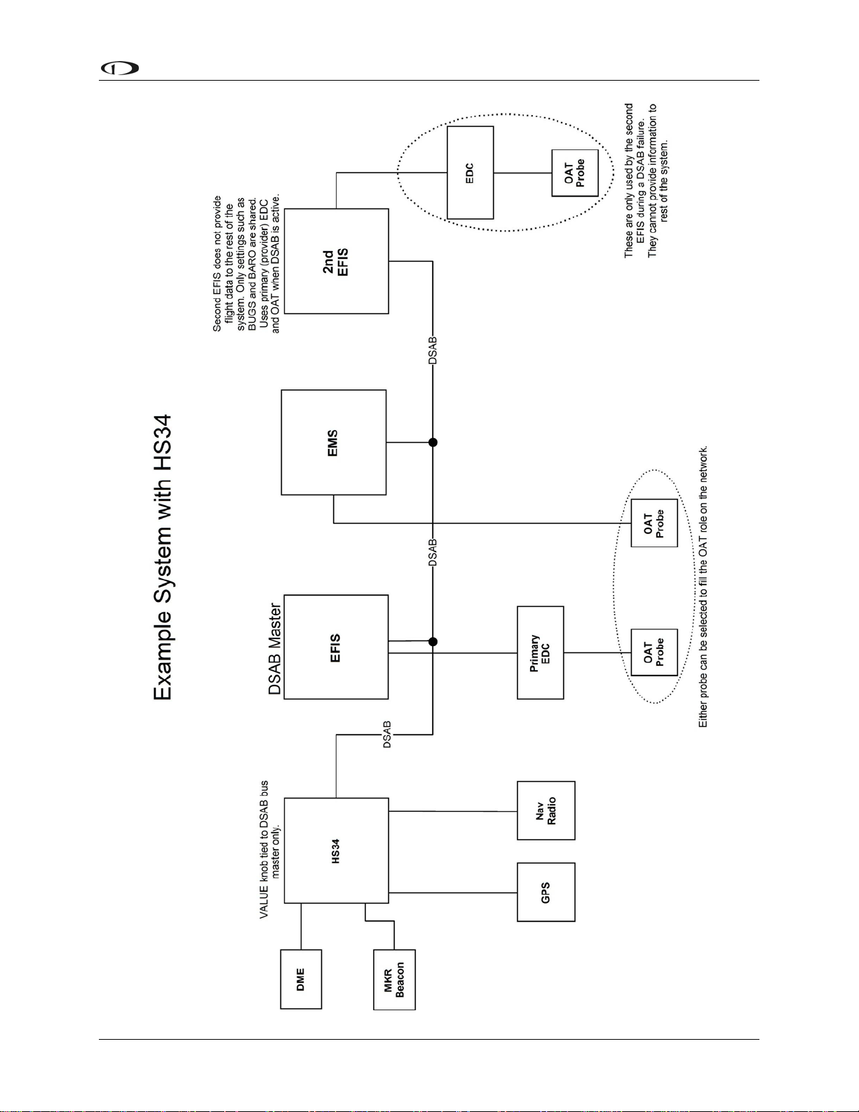
Example Networks
The following two diagrams present example DSAB-connected networks. These examples
illustrate and expand upon some of the concepts discussed above. The first diagram depicts a
system without an HS34 connected, demonstrating where NAV and GPS devices should be
connected. The second diagram depicts a system with an HS34 connected, demonstrating that all
NAV and GPS devices must be connected to the HS34. Both diagrams discuss what devices can
be assigned various roles and what happens when DSAB fails.
5-2 EFIS-D10A Installation Guide
Page 37
DSAB Configuration
EFIS-D10A Installation Guide
5-3
Page 38

DSAB Configuration
Initial Setup
As mentioned at the beginning of this chapter, configure your DSAB network only after all other
installation steps have been performed, including updating all products to the latest version of
firmware available from the Dynon Avionics web site at downloads.dynonavionics.com
begin configuration, enter the EFIS > SETUP > DSAB menu. A full-page menu appears with
three options: STATUS, CONFIGURATION, and BRIGHTNESS. Push DOWN▼ to select
CONFIGURATION and then SEL► to enter the CONFIGURATION submenu. Note that if you
press CONFIGURATION from an EMS-only product (via EMS > SETUP > DSAB), the display
prompts you to begin the configuration process from an EFIS-based product.
If this is not your first time configuring your DSAB network, a prompt appears asking if you
wish to re-configure the network. If you do not want to re-configure, press NO; otherwise, press
YES to proceed with configuration as if this is a first-time install.
The first screen in the configuration process asks you to power on all devices in the system
before pressing CONFIGURE NOW (button 1 or 2). After doing this, a second screen appears
asking you to wait while the instrument detects all other devices connected via DSAB. While
doing this, it assigns both the Bus Master and EFIS roles to itself.
During network detection, the Bus Master attempts to automatically assign as many roles as it
can. The following table describes the logic used in assigning roles for network devices.
. To
Bus Master
EFIS
EMS
OAT
Compass
AP CTRL
PANEL
HS34
How role is assigned
Auto-assigned to instrument user is configuring on.
Auto-assigned to instrument user is configuring on.
If one EMS detected, assigned automatically.
If Bus Master is EMS (i.e., FlightDEK-D180) assigned automatically.
If more than one non-bus-master EMS detected, user must assign.
If one OAT detected, assigned automatically.
If more than one OAT detected, user must assign.
Note that for an OAT to be used it must be connected to an instrument
assigned the EFIS or EMS role (i.e., if configuring DSAB on a
FlightDEK-D180 with no OAT attached, the OAT role cannot be assigned
to another instrument in the system as the FlightDEK-D180 is already
assigned both the EFIS and EMS roles).
Auto-assigned to instrument providing the EFIS/Bus Master roles.
If one AP74 detected, assigned automatically.
If more than one AP74 detected, error displayed: Not a supported
configuration.
If one HS34 detected, assigned automatically.
If more than one HS34 detected, error displayed: Not a supported
configuration.
5-4 EFIS-D10A Installation Guide
Page 39

DSAB Configuration
Roll Servo and Pitch Servo functions are automatically detected and
AP
ROLL/PITCH
SERVO
If the configuration process could not automatically assign the EMS and OAT roles (because
there are 2 or more of either type found on the network), it prompts you to assign each of them to
the instrument of your choice. It then presents a list of all instruments on the network capable of
being assigned each role. Use the DOWN▼ and UP▲ buttons to select the preferred instrument
to provide the given role. The serial number for each unit is displayed next to its product type.
Additionally, with an instrument type selected, pressing IDENT changes that instrument’s
display to a black screen with the text DSAB IDENT shown. If the instrument you wish to
identify is the one which you are currently interacting with, the line changes to read THIS UNIT.
When you have selected the preferred provider for the role, press SELECT to continue in the
process. If necessary, repeat with the next manually assigned role.
At this point, a screen is displayed, stating:
(X) DEVICES FOUND
NETWORK CONFIGURATION IS COMPLETE
assigned during Autopilot Servo Calibration process. See: EFIS > SETUP
> AP > SERVO CALIB.
More than two SV32s or SV42s is not a supported configuration.
Press FINISH to end the configuration. Press UP▲ and SEL► to view the status of all
connected DSAB devices. Press UP▲ or DOWN▼ to scroll through all the devices. Crosscheck the displayed devices against what you actually have installed and connected. Ensure that
the STATUS for each device is listed as ACTIVE.
You may repeat the configuration process as many times as you wish. Whenever you add or
remove an instrument from your network, you must redo the DSAB configuration process.
Note that the following DSAB configurations are not supported:
More than 1 FlightDEK-D180 in the network
More than 1 HS34 in the network
More than 1 AP74 in the network
More than 2 servos in the network
Network Status
The STATUS submenu displays information
on all configured devices, their serial
numbers, their roles on the network, and
their status.
The first line indicates how many devices
are configured on the network. This number
is independent of the number of devices
actually currently turned on and
communicating. It simply reports how many
instruments were present during the most
recent execution of DSAB configuration.
EFIS-D10A Installation Guide 5-5
Page 40

DSAB Configuration
The next several lines indicate the available roles that the selected instrument can provide. A “*”
is placed next to the roles that the instrument is currently providing to the network. If any of
those roles cannot be detected (e.g., the EFIS’s compass has been disconnected), a “?” is
displayed next to that role. Any given instrument in the list can have one of the following
STATUS messages:
ACTIVE – The device is communicating normally on DSAB.
STANDALONE – During configuration as Bus Master, no other DSAB devices were
found.
UPGRADE REQ – Device has a different firmware version than the Bus Master and
thus cannot communicate on DSAB.
OFFLINE – The specified device cannot communicate on DSAB or is powered off.
PEERS LOST – (Only appears on Bus Master) – The Bus Master was configured with
other DSAB devices present; however, all of them are currently offline.
If an instrument’s STATUS field displays UPGRADE REQ, PEERS LOST, or OFFLINE, all of
its provided roles are listed as not detected.
The selected instrument’s serial number is displayed, assisting in identification. Additionally,
pressing IDENT causes the selected instrument’s display to display a black screen with the text
DSAB IDENT shown. If the instrument you wish to identify is the one which you are currently
interacting with, the line changes to read THIS UNIT.
Press DOWN▼ or UP▲ to scroll through each of the other instruments configured in your
network.
5-6 EFIS-D10A Installation Guide
Page 41

6. AUTOPILOT INSTALLATION AND CONFIGURATION
Dynon Avionics’ Autopilot (AP) system is a competitively priced product for the Experimental
& Light Sport Aircraft (LSA) aircraft market. Unlike standalone AP systems, Dynon’s AP is an
enhancement to the Dynon Avionics EFIS-D10A, EFIS-D100, and FlightDEK-D180 products
(beginning with firmware version 5.0). The Dynon Avionics AP provides roll (aileron) and/or
pitch (elevator) control, leveraging the proven sensors, algorithms, and display systems of
Dynon’s modern EFIS products. Another innovative element of the Dynon Avionics AP is that
the servomotors (servos) responsible for actuating the control surfaces are “smart” devices.
Dynon’s servos not only accept commands from the AP but also report “health,” resistance to
commanded movements, motor override (or “slip”), and many other data elements back to the
EFIS. This level of communication between AP control and motors provides the pilot with an
unprecedented degree of awareness of the overall performance of the AP. Dynon currently offers
the following servo models:
Model Number Torque Attachment
SV32 Standard Arm
SV32L Long Arm
SV32C
SV42 Standard Arm
SV42L* Long Arm
SV42C
36 inch-pounds
Capstan
55 inch-pounds
Capstan
* SV42L servo is a special order item – contact Dynon Technical Support for details.
Dynon also offers the AP74 Autopilot Interface Module, which provides dedicated AP control
via panel-mounted buttons and a knob. Dynon offers mounting kits for specific airframes, which
include parts and detailed instructions. Additionally, Dynon Avionics supplies a generic
mounting kit of basic parts that provides a head start for owners of aircraft not currently
supported by our specific kits.
Additional Information and Updates
This guide provides generic mechanical installation guidelines to assist installers while
integrating the Autopilot system into many aircraft. If you purchased a plane-specific kit from
Dynon Avionics, it contains more detailed drawings and diagrams unique to your aircraft. You
can find the list of Dynon’s aircraft mounting kits on the current Price List / Order Form on
Dynon’s secure web site at store.dynonavionics.com. The drawings and installation instructions
of current Dynon Avionics aircraft mounting kits are available on the Dynon web site at
docs.dynonavionics.com
Because the Dynon Avionics Autopilot is a new product and we expect that it will be installed in
a wide variety of aircraft, Dynon’s Internet sites provide up-to-date information on installation
and operation issues:
wiki.dynonavionics.com
continuously-updated online documentation contributed by Dynon employees and customers.
.
– Dynon’s Documentation Wiki provides enhanced, extended,
EFIS-D10A Installation Guide 6-1
Page 42

Autopilot Installation and Configuration
forum.dynonavionics.com – Dynon’s Online Customer Forum is a resource for Dynon Avionics
customers to discuss installation and operational issues relating to Dynon Avionics products. The
Forum is especially useful for pilots with uncommon aircraft or unusual installation issues. For
customers that cannot call Dynon Technical Support during our normal business hours, the
Forum is a convenient way to interact with Dynon Avionics Technical Support. The Forum
allows online sharing of wiring diagrams, photos, and other types of electronic files.
Dynon will continue to develop kits and installation instructions for more aircraft based on
demand. It is also expected that aircraft manufacturers will develop their own mounting kits for
Dynon servos or offer the Dynon AP as a factory option. If Dynon does not currently offer a
mounting kit for your particular aircraft, and you would be inclined to assist in developing a kit
and documentation, please send an introductory email message about your interest to:
betatest@dynonavionics.com.
DSAB Firmware Compatibility
All Dynon instruments connected via DSAB must be running the same firmware version
(currently version 5.4). This applies to the servos and AP74 as well. Because the servos
and AP74 are updated via the DSAB Bus Master EFIS (the EFIS that you wish to control
the AP, and from which you run the CONFIGURE DSAB command), wait until
complete mechanical and electrical installation before performing the software upgrade
steps. See Firmware Upgrades Required For AP Functionality on page 6-13 for more
information.
Compass Calibration Critical For Certain AP Modes
The Dynon Avionics AP requires an accurate magnetic heading to operate efficiently
and comfortably in HDG mode and the radio-based VOR/NAV mode. Therefore it is
critical that the aircraft’s compass be installed correctly, calibrated, and operating well in
all attitudes. If you currently have an EFIS-D10A, and are only using the internal
magnetic compass, Dynon strongly recommends the installation and use of the EDCD10A remote-mounted digital magnetic compass, and properly calibrating it per the
instructions found in Chapter 4: Instrument Installation.
If the Dynon Avionics AP will be used exclusively in GPS NAV or TRK modes, then absolute
accuracy of compass data is somewhat less critical as part of AP operation. But if NAV/GPS
data is lost due to an equipment failure, bad data, loss of signal, etc. the AP will “fail over” to
HDG mode, which uses the magnetic compass data as its source.
6-2 EFIS-D10A Installation Guide
Page 43

Autopilot Installation and Configuration
Autopilot System Electrical Installation
The diagram below provides an overview of the autopilot electrical system. The following
sections describe the electrical installation of each subsystem in detail.
EFIS-D10A Installation Guide 6-3
Page 44

Autopilot Installation and Configuration
SERVO ELECTRICAL INSTALLATION
Dynon Avionics’ servos are supplied with 7 un-terminated wires, each about 8” in length. It is
the responsibility of the installer to decide on connectors and associated wiring. The 7 wires have
the following colors and functions:
Color Function Notes
Red
Black
Green
Blue
Dynon Smart Avionics
Dynon Smart Avionics
Power 10-30 volts DC. Each servo draws up to 2 amps
Aircraft Ground Each servo draws up to 2 amps
Connected in parallel with other DSAB devices
Bus [DSAB] “A”
(Green wire on all Dynon-supplied wiring harnesses)
Connected in parallel with other DSAB devices
Bus [DSAB] “B”
(Blue wire on all Dynon-supplied wiring harnesses)
Connected through a normally-open pushbutton
Yellow
AP Disengage/Control
Wheel Steering (CWS)
Button
switch to Ground (disengages AP when button is
pushed). If two servos are installed, the yellow wire
from each servo is connected in parallel to a single
pushbutton.
DO NOT CUT! During servo installation, Dynon
recommends that this be routed to the cockpit panel
(include sufficient slack behind the panel) if you
want to preserve compatibility of the servo with
Dynon’s “Next Generation” technology. This wire is
White/Green
Reserved for
compatibility with
Dynon “Next
Generation” products
not used with the EFIS-D10A.
DO NOT CUT! During servo installation, Dynon
White/Blue
Reserved for
compatibility with
Dynon “Next
Generation” products
recommends that this be routed to the cockpit panel
(include sufficient slack behind the panel) if you
want to preserve compatibility of the servo with
Dynon’s “Next Generation” technology. This wire is
not used with the EFIS-D10A.
Circuit Breaker/Switch: We recommend that electrical power for the all servos be
protected with an appropriately sized circuit breaker or switch that is accessible to the
pilot while in flight.
Wire Sizing: While it is beyond the scope of this installation guide to advise on specific
types of wiring for a particular aircraft, choice of wiring should be sized to 1) minimize
voltage drop over the length of the particular wiring run, and 2) conduct the amount of
current required by the subsystem without the wiring becoming warm to the touch.
Wiring Installation: Care should be taken such that aircraft wiring is not subjected to
chafing, excessive flexing, or connections / junctions subjected to excessive vibration
which may cause the connection/junction to fail or short-circuit. If the White/Green and
White/Blue wires are extended to the cockpit panel, leave sufficient slack behind the
panel for connection anywhere behind the panel. If the White/Green and White/Blue
wires are not extended to the cockpit panel, as with other unused wires, DO NOT CUT
the wires, but rather insulate the ends of the wires (electrical tape, heatshrink tubing),
bundle, and secure the unused wire.
6-4 EFIS-D10A Installation Guide
Page 45

Autopilot Installation and Configuration
AP CONTROLS ELECTRICAL INSTALLATION
Circuit Breaker/Switch Install a circuit breaker or switch in a location that is accessible to the
pilot while in flight.
AP Disengage/Control Wheel Steering Button
The AP Disengage/CWS button should be in a very accessible location, usually mounted to the
stick or yoke. This button’s primary purpose is to immediately disengage the autopilot. When
configured in the EFIS > SETUP > AP > BUTTON CONFIG menu, this button can also be used
to engage the Autopilot from an “off” status by holding the button for more than 2 seconds.
This button should be a Single Pole, Normally Open, Momentary button. Verify that two
terminals of the button are shorted when the button is pressed and open (no-connect) when the
button is released. One terminal of the button should connect to both servos’ yellow wires, and
the other should connect to ground.
While not required, you may install a 5 kΩ resistor across the AP Disengage/CWS button. When
configured in the EFIS > SETUP > AP > BUTTON CONFIG > RESISTOR INST menu, the
EFIS monitors the disengage line and displays a warning when a broken connection is detected.
AP74 ELECTRICAL INSTALLATION
When installing the AP74, we recommend building enough slack wiring into the D25
connector to allow the AP74 to be removed from its tray with the connector attached.
Use the D-sub pins/connector kit included with your AP74 to make the following connections:
Pin 3: Dynon Smart Avionics Bus (DSAB) “A”, connected in parallel with all other
DSAB B connections (Blue wire on Dynon-supplied wiring harnesses)
Pin 4: Power, 10 - 30 volts DC
Pin 16: Dynon Smart Avionics Bus (DSAB) “B”, connected in parallel with all other
DSAB A connections (Green wire on Dynon-supplied wiring harnesses)
Pin 17: Aircraft Ground
Pin 25: Outer terminal of AP Audio Adjustment Potentiometer (detailed below); If HS34
installed and providing audio to your intercom system, do not connect the AP74 audio
out. If both the HS34 and AP74 Voice/Tone outputs are connected to your intercom,
audio alerts will be distorted.
Ensure that the AP74 audio output is connected similar to the following diagram. The 10 kΩ
variable resistor can be obtained from Radio Shack (P/N 271-1715) or other electronics
suppliers. The potentiometer does not need to be pilot-accessible as it is typically adjusted only
during setup and configuration. See Step 6 - Audio Alerts Configuration on page 6-23.
Outside terminal
To AP74 pin 5 - A
udio
Alert Out
Center ter
minal
To intercom/audio
panel auxiliary input.
Outside term
inal
Aircraft ground
EFIS-D10A Installation Guide
6-5
Page 46

Autopilot Installation and Configuration
Note: As with the optional Dynon HS34, it is acceptable to connect the tone output of EFIS
(DB25 Pin 18) and/or EMS (DB37 Pin 31) in parallel with the tone/voice output of the AP74
(Pin 25) to provide “failover” audio alerts from the EFIS and/or EMS if the AP74 were to fail.
However, do not connect the audio outputs from an HS34 and AP74 in parallel.
Servo Mechanical Installation
Dynon Avionics has researched suitable mounting points for a number of popular aircraft and
offers mounting kits and instructions for them. If you have purchased one of these kits, use the
instructions included with it as your primary guide; the following mechanical installation
information is more general in nature.
For installing Dynon Avionics servos in aircraft for which Dynon does not offer kits, we offer a
“generic” kit of basic parts and basic installation instructions: Dynon P/N 101020-000. The
generic servo push-pull mounting kit includes some of the hardware to mount a servo and
connect to the aircraft controls, but requires the installer to fabricate mounting brackets. This kit
can be used in either pitch or roll applications that use a servo with an output arm (not suitable
for use with pulley/cable servos). Some additional fasteners (not supplied by Dynon) and
brackets will be required depending on the installation method chosen.
CAUTION: Neglecting to properly install and/or use Dynon Avionics AP hardware can
result in failures which could cause loss of aircraft control resulting in aircraft damage,
personal injury, or death. If there are any questions on the part of the installer it is
mandatory to resolve these questions prior to flight.
When installing the servo, you must first determine a mount location for proper interaction with
the existing control system. The mounting point that is chosen must allow the servo arm and
associated linkage to move freely through the entire range of travel. To prevent the possibility of
the servo arm going OVER CENTER, the servo arm must not travel more than a total of +/-60º
from neutral position. When the aircraft controls are centered, the arm of the servo should be
perpendicular to the attaching push rod. If this is not the case, we recommend adjusting the
length of the push rod or consider a different mounting point. For maximum efficiency and the
lightest drag on the flight controls, you should choose the smallest servo that provides sufficient
torque to move and hold the flight controls with a minimum of “slippage”. A diagram of servo
torque versus mount position is shown on page 6-9.
CAUTION: The servo arm must not rotate even near to the point called OVER
CENTER, the point at which the primary aircraft control would “lock up”. Over center
happens when the angle between the servo arm and the attached push rod becomes so
great that the control system cannot drive against the servo arm. To protect against this
possibility, a Range of Motion Limiting Bracket is supplied with each Dynon Avionics
servo. These brackets are drilled so that they can be mounted at different angles as
required (18° intervals). The brackets are supplied for the protection of the pilot, and we
recommend that the Range of Motion Limiting Bracket be installed to ensure that an
OVER CENTER condition cannot occur.
Once a suitable mounting point for each servo has been determined, the next step is to fabricate a
mount for the servo to attach to the aircraft. Generally this will be a bracket made of sheet metal
or corner stock. Dynon recommends using 6061 T6 aluminum with a minimum thickness of
6-6 EFIS-D10A Installation Guide
Page 47

Autopilot Installation and Configuration
0.050” for the best balance of strength to weight. When fabricating a mounting bracket, refer to
the servo dimensions below. Be sure to leave ample room for the arm and attached linkage to
move through a complete range of motion without interference.
CAUTION: In normal operation, Dynon’s servos can reach temperatures that can be
very uncomfortable to, and perhaps cause burns to unprotected skin. Thus, servos should
be mounted in an area, or in such a manner to prevent accidental skin contact. If
mounting the servo in an exposed area is necessary, a shroud should be installed (that
doesn’t restrict ventilation) that protects against accidental skin contact with the servos.
EFIS-D10A Installation Guide 6-7
Page 48
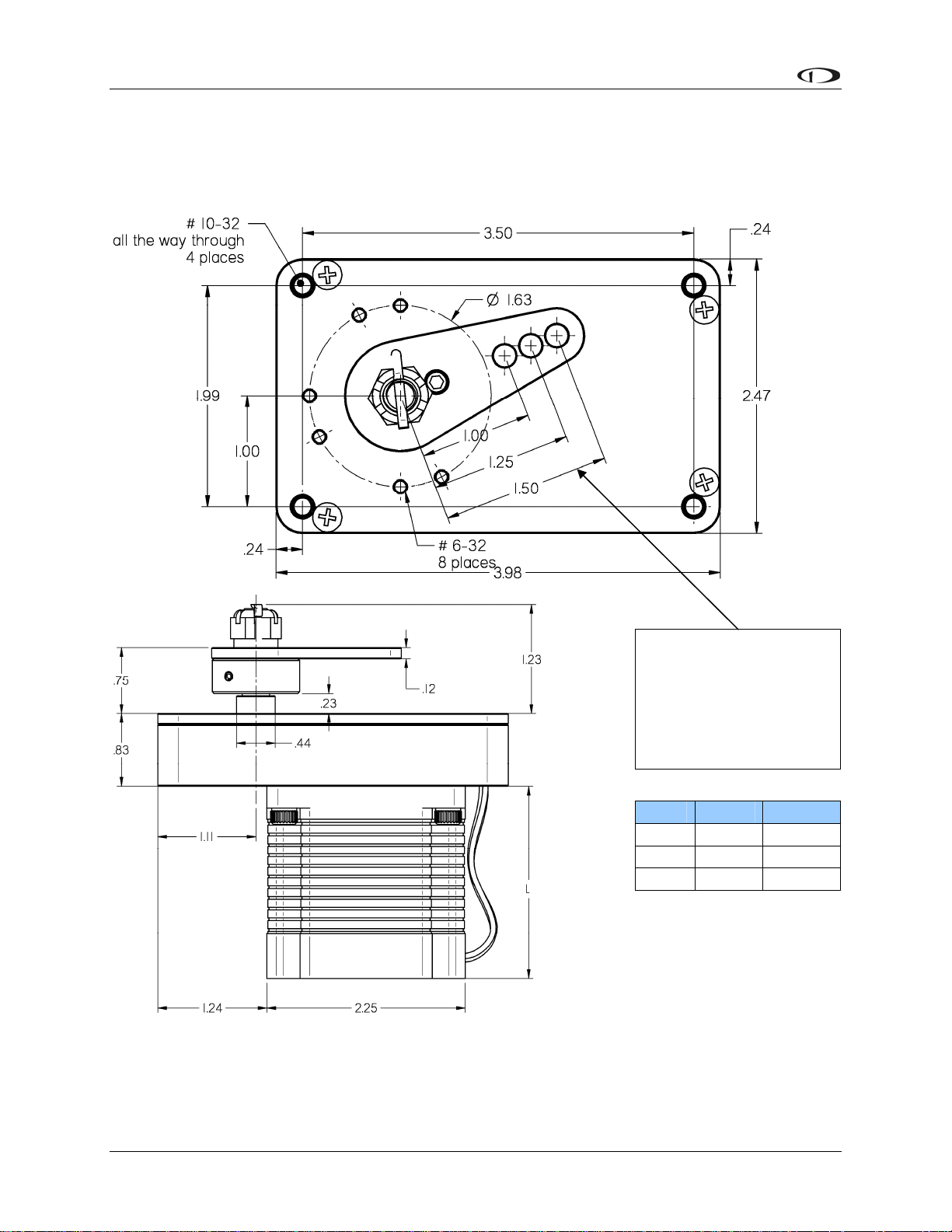
Autopilot Installation and Configuration
SERVO DIMENSIONS
Use the following dimensions (in inches) for reference when planning and implementing your
installation.
Long-arm variants
(not needed in most
installations) have
linkage mount holes
at 1.5”, 1.75”, and
2.0”
L Weight
SV32 2.17” 2 lb
SV42 3.10” 3 lb
SV52 4.02” 4 lb
6-8 EFIS-D10A Installation Guide
Page 49

Autopilot Installation and Configuration
LINKAGE MOUNT POSITION FORCE AND TRAVEL
The two diagrams below illustrate the maximum travel and force available at each linkage
mounting point. As can be seen, the closer you mount the linkage to the shaft, the more force the
servo can deliver. However, this also means the travel of the arm is shorter. Again, ensure that
the servo arm is nowhere near going over-center throughout the entire range of the control
system.
Standard Arm
Max Linear Travel
A: 2.6”, B: 2.2”, C: 1.8”
Max Force @ 100% Torque
SV32 - A: 24lb, B: 29lb, C: 36lb
SV42 - A: 36lb, B: 44lb, C: 55lb
SV52 - A: 48lb, B: 58lb, C: 72lb
Long Arm
Max Linear Travel
A: 3.4”, B: 3.0”, C: 2.6”
Max Force @ 100% Torque
SV32L - A: 18lb, B: 20lb, C: 24lb
SV42L - A: 27lb, B: 31lb, C: 36lb
SV52L - A: 36lb, B: 41lb, C: 48lb
In most instances, it is recommended to connect the servo arm to the control linkages using the
outer-most hole of the servo arm (position A). This position provides the greatest amount of
travel, with the least amount of drive force. If, when testing the autopilot, you find that the servos
cannot adequately drive the control system (indicated by a yellow “slip indicator” in the AP
status at the bottom left of the EFIS screen), you may move the linkage mount point inward,
provided there is still enough travel to accommodate the control system at the servo location.
Using either of the two inner-most holes of the servo arm affects the final amount of force that
EFIS-D10A Installation Guide 6-9
Page 50

Autopilot Installation and Configuration
the servo can exert, arm travel, control surface resolution, and the amount of force required to
shear the brass shear screw. The two inner-most holes of the servo arm should only be used if the
installer fully understands the resulting implications. The diagrams above illustrate the linear
travel and available force for each mount point on the standard and long-arm servos.
CAUTION: Each Dynon Avionics servo includes a precision-machined brass “shear
screw” that pins the servo arm to the servo arm attachment, providing an ultimate
“manual override”. The shear screw will break at the application of 100 inch-pounds of
torque, at which point the servo arm will travel freely. If the brass shear screw is broken
during AP installation or usage, do not replace it with a standard screw - contact Dynon
for a replacement shear screw.
There will be a variety of methods used to install the other end of this control linkage to the
existing mechanicals of the aircraft. Some systems will use a hole drilled into the bell crank as
the point where the servo push rod/rod end combination interfaces with the controls. Others will
use an attachment to existing linkage. Others may attach directly to the control stick itself. It is
up to the installer to decide which method is best in terms of safety and AP functionality.
Installers should always keep in mind the range of motion of the servo. Total servo arm travel
needs to be limited to prevent an OVER CENTER condition (see caution note above), while still
preserving the control surfaces’ full range of motion. Carefully consider the prevention of an
over center condition when selecting the mounting location and linkage attachment point for any
servo installation. The built-in control stops of the aircraft will limit the servo arm travel when
installed correctly. Again, Dynon strongly recommends that the included Range of Motion
Limiting Bracket be installed in order to absolutely prevent the possibility of an over center
condition. The Range of Motion Limiting Bracket should not be used as a normal stop; the
aircraft’s built-in stops should always be the primary range limit.
6-10 EFIS-D10A Installation Guide
Page 51

Autopilot Installation and Configuration
AP74 Mechanical Installation
This section provides you with dimensions, panel location, and mounting information for the
AP74 Dedicated Autopilot Interface.
AP74 DIMENSIONS AND PANEL LOCATION
The diagram below shows the AP74’s outer dimensions. Note that the instrument extends about
3.7” behind the panel, and that a harness can require up to three more inches. Use the dimensions
(in inches) found on the diagram to plan for the space required by the instrument. The front
bezels of the vertically oriented AP74 (100756-000) and are the same height as Dynon’s D100series products and can be mounted close to – or abutted against – one if desired. Plan a panel
location that allows for convenient operation of the knobs and buttons. If you plan on using the
auto-dim feature, ensure that the instrument is in a location where the light sensor (small circle of
rubber on the front of the instrument) can measure the true ambient light conditions in the cabin.
EFIS-D10A Installation Guide
6-11
Page 52
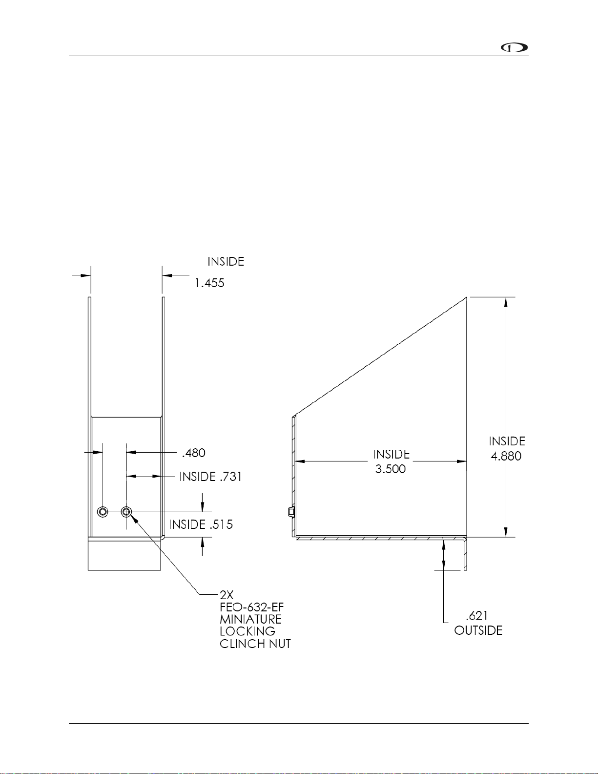
Autopilot Installation and Configuration
MOUNTING BRACKET DIMENSIONS
The dimensions for the included mounting bracket are below. This bracket will work with
varying panel thicknesses in both vertical and horizontal orientations. The primary force used to
secure the instrument to a panel is the “sandwich” action of tightening the bracket behind
through to the instrument bezel in front. The bracket includes a small mounting flange that can
be used to positively secure the bracket to the panel if desired. While not required for secure
mounting (the mounting screw clamps the panel between the bezel and bracket), securing the
bracket to the panel can make removal of the instrument easier by preventing the bracket from
falling behind the panel when removed. If you wish to use the mounting flange, simply match
drill it and rivet or bolt it in the desired spot. See the following section for details on where to
locate the bracket with respect to the hole in the panel. This flange can be trimmed if it is not
needed or if it interferes with other instruments.
6-12 EFIS-D10A Installation Guide
Page 53

Autopilot Installation and Configuration
AP74 MOUNTING
As shown in diagram below, make a rectangular cutout (oriented either vertically or horizontally,
depending on instrument version ordered) of 1.45” by 4.75” (3.69 cm by 12.07 cm). Your AP74
also shipped with a life-sized mounting template for making this cutout and locating the optional
mounting flange holes. If the flange is used, secure it to your panel in whatever way you desire.
Riveting it to the panel is ideal, but drilling holes for mounting screws and nuts also works.
Upon locating the mounting bracket behind your panel, slide the instrument into it. The tapered
mounting screw fits into one of the PEM nuts at the back of the mounting bracket. Use the
included 7/64” Allen wrench to secure the mounting screw into the bracket. As you screw the
mounting screw tighter, the unit will be pulled back into the panel until the bezel sits flush. If the
bracket is installed without the assistance of the mounting flange, it will also be drawn forward
into the back of the panel when tightened. Tighten until the flange and bracket are securely
fastened to the panel.
Firmware Upgrades Required For AP Functionality
Because servo and AP74 firmware is upgraded at the same time as the Bus Master EFIS,
servo and AP74 power must be ON when EFIS firmware is upgraded.
To use the Dynon Avionics AP, the EFIS and all other Dynon products in the DSAB network
must be running the same firmware version (currently 5.4). This includes EFIS, EMS (including
those configured as backup/slave units), HS34, AP74, servos, and the EDC-D10A compass.
EFIS, EMS, and HS34 products must be individually upgraded via their individual serial ports
connected to a PC and running the latest version of the Dynon Avionics Product Support
Program. Autopilot servos and the optional AP74 are upgraded as part of the upgrade of
the DSAB Bus Master EFIS (as is the EDC-D10A). To ensure reliable operation, all Dynon
devices should be upgraded to the same version of firmware; mismatched versions of firmware
on different devices can cause unreliable operation.
EFIS-D10A Installation Guide 6-13
Page 54

Autopilot Installation and Configuration
Detailed instructions for performing firmware upgrades are contained in the “Help” function of
the Dynon Avionics Product Support Program which is available on the Dynon Avionics web
site at downloads.dynonavionics.com.
If you are using a GPS connected to your Dynon EFIS and will be using GPS as an input
for the AP, please upgrade your GPS to the most current firmware available for it.
Dynon’s testing has revealed certain incompatibilities with older versions of GPS
firmware that are corrected with current GPS firmware. Procedures for GPS firmware
upgrades vary by manufacturer; consult your GPS manual for the firmware upgrade
procedure. Additionally, some GPS units must be configured with specific settings to
work properly with Dynon’s instruments. More detail on compatibility with, and settings
for various GPS units is available on the Dynon Avionics web site at
wiki.dynonavionics.com
AP Servo Configuration
This section guides the installer through all the steps necessary to install, configure, and tune the
Autopilot software on the EFIS/servo system. The AP operation functions dealt with here are
primarily focused on configuration and tuning. Pilots should consult the EFIS-D10A Pilot’s User
Guide for a comprehensive description of AP operation.
.
Note: Before proceeding, verify that power is ON for all EFIS, EMS, HS34, AP74 and servo(s).
Note: If your system has more than one Dynon EFIS (that communicates over DSAB), the
configuration of most AP functions can only be performed from the EFIS configured as the
DSAB Bus Master (see Network Concepts on page 5-1).
CONFIGURATION OVERVIEW
1. Configure DSAB (required to be performed on the ground)
2. Servo Calibration & Initial Servo Test (required to be performed on the ground)
3. Roll Servo Initial Setup (recommended to be performed on the ground)
4. Pitch Servo Initial Setup (recommended to be performed on the ground)
5. Disengage/CWS Button Configuration (recommended to be performed on the ground)
6. Audio Alerts Configuration (recommended to be performed on the ground)
7. Prepare for Flight Test (recommended to be performed on the ground)
8. Roll Servo Flight Calibration (recommended to be performed in flight under safe
conditions)
9. Pitch Servo Flight Calibration (recommended to be performed in flight under safe
conditions)
STEP 1 - CONFIGURE DSAB
This step sets up the DSAB network so that the EFIS can communicate with the servo(s),
optional AP74, and any other Dynon products on the DSAB network.
As a safety precaution, while the Configure DSAB procedure is being performed, AP
functionality is disabled.
On the EFIS, perform the following:
6-14 EFIS-D10A Installation Guide
Page 55

Autopilot Installation and Configuration
Enter the EFIS > SETUP > DSAB > CONFIGURATION menu.
ARE YOU SURE YOU WANT TO RE-CONFIGURE THE NETWORK?
Press YES
ARE ALL NETWORKED DEVICES POWERED ON?
Press CONFIGURE NOW
PLEASE WAIT DETECTING ALL NETWORK DEVICES
Wait up to 1 minute
(X) DEVICES FOUND NETWORK CONFIGURATION IS COMPLETE
shows the correct numb Verify that this
all expected de
Press FINISH
Press UP▲ > and then SEL► to select the STATUS menu. The Bus Master EFIS shou
be displayed, showing active roles and status. Verify that STATUS (at bottom) shows
ACTIVE.
Press DOWN▼ once for each device in the network. Verify that the STATUS for each
device shows ACTIVE. If the status displays UPGRADE REQ, that instrument must
be updated to the same version of firmware as the Bus Master EFIS. If the
instrument displaying UPGRADE REQ is one or more of your servos and/or AP74 (mos
commonly when these devices were purchased separately from your EFIS), you must
perform the upgrade via the Bus Master EFIS, even
firmware.
After the above verification, press BACK > EXIT
STEP 2 - SERVO CALIBRATION AND SERVO TEST
The Servo Calibration procedure identifies the orientation and range of motion of each servo.
The Servo Test procedure verifies that each servo is configured properly by moving the control
surfaces, and requiring the pilot to verify correct movement. Un
the EFIS does not display the AP status or operation interface.
vices are powered on.
er of devices. If not, check wiring and ensure that
if the EFIS is already at version 5.4
til this procedure is completed,
ld
t
If Airspeed Color Thresholds have not been configured, Servo Calibration and Servo T
cannot proceed, and the EFIS displays an error message. To configure Airspeed Color
Thresholds, see Configure Airspeed Color Thresholds on page 4-7.
Note: Servo calibration (SERVO CAL) and servo test (SERVO TEST) is a combined procedure
when Servo Calibration is completed successfully, you are prompted to perform Servo Test.
After a successful servo calib
whenever desired.
Note: The following steps assume that two servos are installed to provide AP control of Pitch
and Roll functions. If only a Pitch or Roll ser
sections.
On
the EFIS, perform the following:
Enter the SETUP > AP > SERVO CALIB menu.
EFIS-D10A Installation Guide 6-15
ration, the SERVO TEST procedure can be performed on its own
vo has been installed, skip the non-applicable
est
;
Page 56

Autopilot Installation and Configuration
2 SERVO(S) FOUND PLEASE CENTER ALL CONTROL SURFACES AND MAKE SURE
THEY HAVE A FREE RANGE OF MOTION. PRESS DISCONNECT SWITCH TO
CONTINUE.
Follow all onscreen instructions, moving the controls to each position, pressing the
Disengage/CWS Button to confirm each position. This process calibrates the autopilot to
detect the orientation and range of each servo.
If calibration was successful:
CALIBRATION WAS SUCCESSFUL. ROLL FOUND. PITCH FOUND. PRESS OK BELOW
OR PRESS DISCONNECT SWITCH TO CONTINUE.
Press the AP Disengage/CWS Button or OK button on the EFIS.
If calibration was unsuccessful, an error message is displayed, describing the reason. The
most common causes are not enough travel being detected, or too much travel. In either
case, mechanical adjustments must be made.
After successful completion of the calibration, the system automatically continues into SERVO
TEST Mode. An initial SERVO TEST must be performed before the autopilot is usable. If the
initial SERVO TEST is canceled, the AP status display at the lower left of the EFIS screen
shows “TST” as the status for the installed servo(s).
After successful calibration the screen displays:
PLEASE CENTER ALL CONTROL SURFACES AND MAKE SURE THEY HAVE A FREE
RANGE OF MOTION. PRESS OK BELOW TO BEGIN THE TEST.
Follow all onscreen instructions, moving the controls to each position, pressing the OK
button to confirm each position. This process verifies that the controls move to the
correct position, and ensures that the Disengage/CWS Button properly disengages the
servos.
Note: After successful completion of Configure DSAB, Servo Calibration, and Servo Test, the
AP mode is enabled. The following occurs:
The AP status indicator is displayed at
the lower left of the EFIS screen
(shown at right).
The AP button is present on the EFIS
menu, replacing the BUGS menu
(which is now located within the AP menu).
All bugs (IAS, Heading, and Altitude) are turned hollow.
With an autopilot installed, the heading and altitude bugs
are only filled in when those modes are engaged (HDG,
TRK, ALT hold).
The EFIS now has a record of which servo performs which function and the particular
range of motion it will be executing.
If servos are swapped or replaced, Servo Calibration must be performed again.
6-16 EFIS-D10A Installation Guide
Page 57

Autopilot Installation and Configuration
STEP 3 - ROLL SERVO INITIAL SETUP
We recommend that you perform the following on the
ground at zero airspeed.
Step 3a – Set Roll Servo Torque: The ROLL
SERVO > TORQUE parameter specifies how much
torque the servos will exert before slipping. Servo slip
is indicated by a yellow background on the slipping
axis in the AP status indicator. Torque must be set
high enough to prevent any slip due to air loads, but
low enough that the pilot can comfortably override
the AP should the need arise. If the servo slips continuously, the AP cannot fly the aircraft.
Torque is specified in % of maximum the servo is capable of exerting. Minimum: 10%,
maximum 100%, default: 100%.
On the EFIS, perform the following:
If not already in the SETUP > AP menu, enter the menu and select ROLL SERVO and
press SEL►
(TORQUE value is highlighted)
Press DEC - and INC + to adjust TORQUE to preferred initial setting for the aircraft.
It may take some experimentation to find the right value for your aircraft, but if you are
comfortable overriding the servo with the default value of 100%, it is safe to leave that setting at
the default value. To test servo override, exit the SETUP > AP menu and return to the main EFIS
menu. Center the aircraft controls. Enter the EFIS > AP menu and press HDGOFF. Note that the
mode toggles to HDGON, the HDG bug synchronizes to the current heading, and the roll servo
engages. Ensure that the controls do not deviate far from center.
If you have an AP74 installed and configured, you can accomplish this same procedure
by doing the following: Push the HDG button to ensure that it is lit; push the ALT button
until it is not lit. Push the AP button to engage the AP in Heading Hold mode.
Now, take the controls and override the servo by moving to either roll left or roll right
(remember, you are only overriding the roll servo, so you should feel no resistance in the pitch
axis). Ensure that you are comfortable with the amount of force it takes to override the servo. If
you are not, decrease the roll servo TORQUE value by 10% and repeat the test.
Step 3b – Set Roll Servo Sensitivity: The ROLL SERVO > SENSITIVITY parameter specifies
the how fast or slow the AP responds to deviations between commanded direction and actual
heading or track. If Sensitivity is set too low, the aircraft will “wallow” during changes in
heading. If Sensitivity is set too high, the aircraft will be “twitchy,” with frequent, fast,
aggressive adjustments. Sensitivity is specified in digits. Minimum: 1 (low sensitivity),
maximum: 25 (high sensitivity), default: 10.
This parameter can be tuned in flight; leaving it at the default of 10 is sufficient for initial setup.
If the autopilot is not as “decisive” as you’d like, increase this value; if it is too aggressive,
decrease it.
On the EFIS, perform the following (continuing from TORQUE):
EFIS-D10A Installation Guide 6-17
Page 58

Autopilot Installation and Configuration
DOWN▼ > (SENSITIVITY value is highlighted)
Press DEC - and INC + to adjust SENSITIVITY to preferred initial setting for the
aircraft.
Step 3c – Set Roll Servo Turn Rate Limit: The ROLL SERVO > TRN RT LMT parameter
specifies the desired average turn rate for AP-commanded turns. For example, a setting of 3.0°/S
will ideally complete a 90° turn in 30 seconds. Due to flight dynamics and the time it takes the
Autopilot to initiate a turn, there may be points during a turn where the target Turn Rate Limit is
slightly exceeded. Turn Rate Limit is specified in °/s (average degrees of turn per second).
Minimum: 0.5°/s, maximum: 3°/s, default: 1.5°/s.
On the EFIS, perform the following (continuing from SENSITIVITY):
DOWN▼ > (TRN RT LMT value is highlighted)
Press DEC - and INC + to adjust TRN RT LMT to preferred initial setting for the
aircraft.
Firmware version 5.3 introduces an alternate set of control algorithms which may
improve roll performance in some aircraft. To try this mode simply set TRN RT LMT to
0. The autopilot will more directly control bank angle instead of targeting a specific turn
rate. The maximum bank angle that the autopilot allows continues is still limited by the
BANK LIMIT parameter. In this mode, set the BANK ANGLE LIMIT to the maximum
value you want the autopilot to use in a turn (see below).
Step 3d – Set Roll Servo Bank Limit: The BANK LIMIT parameter specifies a maximum bank
angle which the AP will not exceed during turns. Setting an appropriate Bank Limit protects
against overbank conditions. If the BANK LIMIT setting is reached during a turn, the AP limits
the bank to that value and then reduces it as needed to complete the turn.
If BANK LIMIT is reached, the Turn Rate Limit (set previously) is ignored until the aircraft
returns to within 5º of level in the roll axis.
To choose an appropriate BANK LIMIT, calculate the bank angle that results from your desired
turn rate limit and cruising airspeed; then set the BANK LIMIT to at least 5° above this value. If
this bank angle value is a number that you are not comfortable with, decrease the target TRN RT
LMT (set above). Minimum: 05°; maximum; 45°, default: 35°.
On the EFIS, perform the following (continuing from TRN RT LMT):
DOWN▼ >(BANK LIMIT value is highlighted)
Press DEC - and INC + to adjust BANK LIMIT to preferred initial setting for the
aircraft.
BACK > EXIT
STEP 4 – PITCH SERVO INITIAL SETUP
We recommend that you perform the following on the
ground at zero airspeed.
Step 4a – Set Pitch Servo Torque: The PITCH
SERVO > TORQUE parameter specifies how much
torque the pitch servo will exert before slipping.
6-18 EFIS-D10A Installation Guide
Page 59

Autopilot Installation and Configuration
Servo slip is indicated by a yellow background on the slipping axis in the AP status indicator.
Torque must be set high enough to prevent any slip due to air loads, but low enough that the pilot
can override the AP should the need arise. If the servo slips continuously, the AP cannot fly the
aircraft. Torque is specified in % of maximum the servo is capable of exerting. Minimum: 10%,
maximum 100%, default: 100%.
On the EFIS, perform the following:
If not already in the SETUP > AP menu, enter the menu and select PITCH SERVO and
press SEL►
(TORQUE value is highlighted)
Press DEC - and INC + to adjust TORQUE to preferred initial setting for the aircraft.
It may take some experimentation to find the right value for your aircraft, but if you are
comfortable overriding the default value of 100%, it is safe to leave that setting at the default
value. To test servo override, exit the SETUP > AP menu and return to the main EFIS menu.
Center the aircraft controls. Enter the EFIS > AP menu and press ALTOFF. Note that the mode
toggles to ALTON, the ALT bug synchronizes to the current altitude, and the pitch servo
engages. Ensure that the controls do not deviate far from center.
If you have an AP74 installed and configured, you can accomplish this same procedure
by doing the following: Push the ALT button to ensure that it is lit; push the HDG button
until it is not lit. Push the AP button to engage the AP in Altitude Hold mode.
Now, take the controls and override the servo by moving to either pitch down or pitch up
(remember, you are only overriding the pitch servo, so you should feel no resistance in the roll
axis). Ensure that you are comfortable with the amount of force it takes to override the servo. If
you are not, decrease the roll servo TORQUE value by 10% and repeat the test.
Step 4b – Set Pitch Servo Sensitivity: The PITCH SERVO > SENSITIVITY parameter
specifies the how fast or slow the AP responds to deviations between commanded altitude and
actual altitude. If Sensitivity is set too low, the aircraft will “wallow” during changes in altitude.
If Sensitivity is set too high, the aircraft will be “twitchy,” with frequent, fast, aggressive
adjustments. Sensitivity is specified in digits. Minimum: 1 (low sensitivity), maximum: 25 (high
sensitivity), default: 10.
This parameter can be tuned in flight; leaving it at the default of 10 is sufficient for initial setup.
If the autopilot is not as “decisive” as you’d like, increase this value; if it is too aggressive,
decrease it.
On the EFIS, perform the following (continuing from TORQUE):
DOWN▼ > (SENSITIVITY value is highlighted)
Press DEC - and INC + to adjust SENSITIVITY to preferred initial setting for the
aircraft.
Advanced Pitch Gain and Rate Adjustments
There are several additional advanced parameters that can be used to fine tune the performance
of the pitch axis. They should be considered secondary to the primary Pitch Axis Sensitivity
adjustment. When used, they should be adjusted in the following order:
EFIS-D10A Installation Guide 6-19
Page 60

Autopilot Installation and Configuration
Pitch Gain: Use only after sensitivity is set as well as it can be. Increase gradually if
airplane does not settle on altitude. The default setting is 20.
Altitude Gain (ALT GAIN): Use only after sensitivity and all of the above settings are set
as well as they can be. Increase gradually if airplane levels off too soon. Reduce
gradually if airplane overshoots altitudes after climbs and descents. The default setting is
6.
Pull Rate: Use only after sensitivity and all of the above settings are set as well as they
can be. Controls the rate the AP will push or pull when changing vertical speed. The
default setting is 10.
VSI Gain: Use only after sensitivity and all of the above settings are set as well as they
can be. Increase gradually if overshooting altitude after climbs or descents, decrease if
rounding out too early. The default setting is 15.
G Error Gain (G ERR GAIN): Use only after sensitivity and all of the above settings are
set as well as they can be. Increase gradually if vertical speed changes are not smoothed
enough; Decrease if ride is too harsh. G Error Gain adjustments affect the most
noticeable changes while the aircraft is in turbulence. The default setting is 10.
G Error Limit (G ERR LIM): Use only after sensitivity and all of the above settings are
set as well as they can be. Controls the max additional G the autopilot will push or pull to
control vertical speed (up to the G limiter). G Error Limit adjustments affect the most
noticeable changes while the aircraft is in turbulence. The default setting is 25.
Step 4c – Set Airspeed Minimum: The PITCH SERVO > AIRSP MIN parameter must be set to
at least (and defaults to) 30% above VS1, which should be set to the specifications of your
aircraft in the EFIS > SETUP > IASCLR menu. The AP cannot be engaged at airspeeds below
Airspeed Minimum, with the exception of 0 knots, allowing for ground testing. When flying at
airspeeds lower than AIRSP MIN, the AP status indicator displays “SPD” for both axes, and
cannot be engaged.
When the AP is engaged and aircraft airspeed drops below the minimum, the AP enters an
airspeed hold mode, sacrificing altitude hold performance to maintain the minimum airspeed.
When the aircraft’s altitude drops below the target ALT bug and the AP cannot pitch the aircraft
up without dropping below the minimum airspeed, the EFIS presents the prompt:
MIN AIRSPEED – ADD POWER
Airspeed Minimum is specified in knots, kilometers/hr, or miles/hr, depending on the units
chosen in the EFIS > SETUP > UNITS > IAS menu. Minimum/default: 30% above V
S1
.
To set the AIRSP MIN, perform the following (continuing from Pitch Servo Sensitivity):
DOWN▼ > (AIRSP MIN: value is highlighted)
Press DEC - and INC + to adjust APRSP MIN to preferred initial setting for the aircraft.
Step 4d – Set Pitch Servo Airspeed Maximum: The PITCH SERVO > AIRSP MAX
parameter cannot be set to a value above 95% of VNE, which should be set to the specifications
of your aircraft in the EFIS > SETUP > IASCLR menu. The AP cannot be engaged at airspeeds
above Airspeed Maximum. When flying at airspeeds above AIRSP MAX, the AP status
indicator displays “SPD” for both axes, and cannot be engaged.
6-20 EFIS-D10A Installation Guide
Page 61

Autopilot Installation and Configuration
When the AP is engaged and aircraft airspeed rises above the maximum, the AP enters an
airspeed hold mode, pitching the aircraft up to prevent exceeding the maximum airspeed.
When the aircraft’s altitude rises above the target ALT bug and the AP cannot pitch the aircraft
down without going above the maximum airspeed, the EFIS presents the prompt:
MAX AIRSPEED – REDUCE POWER
Airspeed Maximum is specified in knots, kilometers/hr, or miles/hr, depending on the units
chosen in the EFIS > SETUP > UNITS > IAS menu. Maximum/default: 5% below VNE.
To set the AIRSP MAX, perform the following (continuing from AIRSP MIN):
DOWN▼ > (AIRSP MAX: value is highlighted)
Press DEC - and INC + to adjust APRSP MAX to preferred initial setting for the aircraft.
Step 4e – Set Pitch Servo VSPD Maximum: The PITCH SERVO > VSPD MAX parameter is
specified in feet/minute (or meters/second, if the setting chosen in the EFIS > SETUP > UNITS
> ALT is METERS). This parameter sets the average vertical speed the autopilot will command
for climbs and descents. If you set this value above a vertical speed the aircraft can achieve, the
AP will run into the airspeed limiter in climbs and descents. Minimum: 100 feet/minute; default:
500 feet/minute; maximum: 4,000 feet/minute.
On the EFIS, perform the following (continuing from Pitch Servo Airspeed Maximum):
DOWN▼ > (VSPD MAX: value is highlighted)
Press DEC - and INC + to adjust VSPD MAX to preferred initial setting for the aircraft.
> BACK > EXIT
STEP 5 – DISENGAGE/CWS BUTTON CONFIGURATION
We recommend that you perform the following on the ground at zero airspeed.
Step 5a – Enable/Disable Hold to Engage: Setting HOLD TO ENGAGE to Y allows you to
engage the Autopilot by holding the Disengage/CWS Button for more than 2 seconds. This
allows for a convenient alternative to engaging the Autopilot via the menus and/or AP74 AP
button. Default is N.
When this mode is active, anytime the autopilot is disengaged you can engage it by pressing and
holding the Disengage/CWS Button for more than 2 seconds. Note that after 2 seconds, the AP
status indicator at lower left of the EFIS screen shows AP:CWS-CWS. This indicates that the
servos are in Control Wheel Steering mode and are waiting for the button to be released before
engaging.
Step 5b – Enable/Disable Broken Disengage Line Detect: The BUTTON CONFIG >
RESISTOR INST parameter should only be set to Y if the optional 5 kΩ resistor is installed
across the Disengage/CWS Button, as shown on page 6-3. If the resistor is installed and this
parameter is set to Y, the EFIS continuously monitors the AP Disengage/CWS Button circuit for
proper resistance. If a broken line is detected the following message is displayed on the EFIS:
AUTOPILOT DISCONNECT LINE BROKEN
If the AP is engaged when this condition is detected, it will remain engaged.
EFIS-D10A Installation Guide 6-21
Page 62

Autopilot Installation and Configuration
Set to Y if the optional 5 kΩ resistor is installed across the 2 terminals of the Disengage/CWS
Button. Set to N if the resistor is not installed. Default is N.
Step 5c – Enable/Disable Control Wheel Steering: When set to Y, the BUTTON CONFIG >
CTRL WHEEL STEER > ENABLED option enables a secondary mode of the AP
Disengage/CWS Button. This mode allows you to be flying under AP control, press and hold the
Disengage/CWS Button while flying to a new heading and/or altitude, then release the button to
reengage the Autopilot. The Autopilot will reengage in the mode set by the MODE parameter,
described below. Default is N
On the EFIS, perform the following (continuing from Button Configuration Resistor Installed):
DOWN▼ > (-CTRL WHEEL STEER- ENABLED: value is highlighted)
SEL► > Set to Y or N per the explanation above.
Step 5d – Set Control Wheel Steering Mode: When the Control Wheel Steering ENABLED
parameter is set to Y, the MODE parameter selects between two different ways of reengaging the
Autopilot after the AP Disengage/CWS Button is released:
Last Heading and/or Altitude (LAST HDG/ALT) - the AP is engaged and returns to the
selected Heading and/or Altitude
Hold Heading and/or Altitude (HOLD HDG/ALT) - the AP is engaged and changes the
selected Heading and/or Altitude to match the current Heading and/or Altitude
Default is HOLD HDG/ALT.
On the EFIS, perform the following (continuing from Button Configuration Control Wheel Steer
Mode):
DOWN▼ > (-CTRL WHEEL STEER- MODE: value is highlighted)
SEL► > Set to HOLD HDG/ALT or LAST HDG/ALT per the explanation above.
> BACK > EXIT
6-22 EFIS-D10A Installation Guide
Page 63

Autopilot Installation and Configuration
STEP 6 - AUDIO ALERTS CONFIGURATION
This section applies only if you have installed the optional AP74.
The optional AP74 can act as the sole audio alert source for all DSAB-connected Dynon
instruments. The audio output of the AP74 reports both EFIS and EMS alerts; each type of alert
can be configured to be either voice or tone formats. When the AP74 is connected to your
system, audible alerts are still generated by both EMS- and EFIS-based instruments. If you
would like the AP74’s audio out to be your only source for Dynon product audible alerts,
disconnect the audio out connections on your other DSAB-connected Dynon products.
The AP74 and HS34 have identical voice output capabilities. If an HS34 Voice/Tone
output is already connected to the aircraft intercom, do not connect the AP74 Voice/Tone
output. If the Voice/Tone output of both an HS34 and an AP74 are connected in parallel,
audio alerts will be distorted.
To configure AP74 audio alerts, enter the EFIS > SETUP > AP menu, scroll down to AUDIO
ALERTS, and press SEL►. The following
points describe the options available for
each setting:
EMS: EXT TONE / EXT VOICE – Sets
whether you want the AP74 to report tones
or voice alerts during EMS alarm
conditions. This setting has no effect on the
“direct” audio output of the EMS.
EFIS: EXT TONE / EXT VOICE – Sets
whether you want the AP74 to report tones
or voice alerts during EFIS alarm
conditions. The “direct” audio output of the
EFIS is muted*.
EFIS: EFIS TONE – tones are generated
through the “direct” audio output of the
EFIS and the audio output of the AP74 is
muted.
AOA: EXT TONE – During an AOA
alarm condition, tones are generated
through the AP74 audio output and the
EFIS “direct” audio output is muted*.
AOA: EXT VOICE – During an AOA
alarm condition, voice is generated through
the AP74 audio output simultaneously with
a “progressive” tone from the EFIS “direct”
audio output.
AOA: EFIS TONE – Tones are generated
through the “direct” audio output of the
COOLANT TEMPERATURE HIGH
COOLANT PRESSURE HIGH/LOW
All other EMS alerts vocalized “EMS ALERT”
CLIMB/DESCEND (Altitude alerter)
EMS AUDIO ALERTS
RPM HIGH
MANIFOLD PRESSURE HIGH
OIL PRESSURE HIGH/LOW
OIL TEMPERATURE HIGH/LOW
EGT [1..6] HIGH/LOW
EGT SPAN
CHT [1..6] HIGH/LOW
CHT SPAN
CHT [1..6] SHOCK
FUEL LEVEL [1..4] LOW
FUEL PRESSURE HIGH/LOW
FUEL FLOW HIGH
VOLTAGE HIGH/LOW
CURRENT HIGH/LOW
EFIS AUDIO ALERTS
ALTITUDE (Altitude alerter)
AUTOPILOT DISCONNECT
STALL
TIMER EXPIRED
DSAB ERROR
EFIS-D10A Installation Guide 6-23
Page 64

Autopilot Installation and Configuration
EFIS and the audio output of the AP74 is muted.
* If an AP74 failure is detected during this condition, the EFIS “direct” audio output (tones only)
is automatically re-enabled (fail-over).
Selecting TEST VOICE OUTPUT and then pressing SEL► produces an audible voice test
(“DYNON AVIONICS”) on the audio output line. This allows you to verify connections and
volume on the ground. Turn the potentiometer to adjust the volume to your preference.
If an AP74 is not connected or not configured for DSAB, the following message is
displayed:
THIS SETUP MENU IS
DISABLED BECAUSE
NO AP74/76
CONNECTED
STEP 7 – PREPARE FOR FLIGHT TEST ON CLEAR, VFR DAY
The remaining configuration steps are done while flying. At many points, the pilot’s
attention will be divided between documentation, configuring the EFIS, and maintaining
situational awareness. Before commencing these configuration steps, ensure that you
have adequate altitude, clear weather, no traffic, no obstructions in the flight path, great
visibility, etc. If possible, bring someone along on the first configuration flight.
If AP behavior, performance, or interference with the controls is cause for concern while flying,
remember that the AP can be disengaged in any of the following ways:
1. Turn off the AP circuit breaker/switch or remove the fuse.
2. Push the Autopilot Disengage pushbutton.
3. In the EFIS, Select AP > HDGON - push to turn off Roll servo (changes to HDGOFF);
ALTON - push to turn off Pitch servo (changes to ALTOFF)
4. If you have an AP74 installed, push the AP button (The AP indicator turns off, but the
Mode “armed” lights remain on).
Before commencing the remaining AP configuration steps, verify (on the ground with 0 airspeed
indicated on the EFIS) that the AP status indicator displays (for a 2-axis system):
AP:OFF-OFF
Verify the following if you have a GPS installed, configured, and powered on:
Magenta GPS information is displayed on the HSI page.
In the EFIS > AP > MODE menu, both the HDG and TRK options are displayed.
6-24 EFIS-D10A Installation Guide
Page 65

Autopilot Installation and Configuration
STEP 8 – ROLL SERVO FLIGHT TUNING
This set of procedures tunes the settings in the AP > ROLL SERVO menu for the particular
flight characteristics of the aircraft in heading holds and turns.
Note: While this procedure is described assuming you are using HDG mode – where the AP’s
goal is to keep the aircraft’s magnetic heading aligned with the HDG bug – it can be performed
in TRK mode – where the AP’s goal is to keep the aircraft’s ground track aligned with the bug –
instead.
Step 8a – Verify preferred Turn Rate Limit and Bank Angle Limit
On the EFIS, perform the following:
SETUP > AP > ROLL SERVO
Verify that the TRN RT LMT and BANK LIMIT parameters are set to values you are
comfortable with.
If you wish to change either of these values prior to or during flight, push DOWN▼ to
select the value, and then DEC - or INC + to modify it.
Step 8b – Ensure that the aircraft is in trim.
Because this test procedure tunes only the Autopilot’s control of roll (so that roll performance
can be isolated), only start the procedure when the aircraft is in neutral trim. During the
following procedures, ensure that your altitude stays constant.
Step 8c – Engage the AP in HDG mode
On the EFIS, perform the following:
EFIS > AP > HDGOFF.
The EFIS synchronizes the HDG bug to the current heading, the Autopilot engages with
the heading bug as its target, and the indicator turns to HDGON.
If you have an AP74 installed and configured, the following performs the same function:
Push HDG button (activates ROLL servo); ensure that the red HDG indicator lights are
on.
Ensure that the ALT indicator lights are off; push the ALT button if they are not.
Push the AP button to engage in HDG mode.
The AP status indicator at the lower left of the EFIS screen displays: AP:HDG-OFF
Step 8d – Allow a few minutes of stable flight under AP control
Note that the AP is only flying in Heading Hold Mode, so you will need to control the aircraft in
pitch. Ensure that you are not affecting the Autopilot’s control of the roll axis, so you can
determine the AP’s heading hold and change performance.
Step 8e – Adjust roll servo TORQUE and/or SENSITIVITY values as needed
On the EFIS, observe the AP status indicator (lower left corner - AP:HDG-OFF) while the AP
flies. If the HDG indicator is frequently highlighted yellow, that is an indication that the Roll
Servo is slipping and the torque needs to be increased. Occasional slips due to turbulence are
acceptable.
EFIS-D10A Installation Guide 6-25
Page 66

Autopilot Installation and Configuration
If necessary, adjust the TORQUE value in the EFIS > SETUP > AP > ROLL SERVO menu.
If you have adjusted the roll servo TORQUE value to 100% and are still seeing frequent
slips, you may need to move the linkage attachment point on the roll servo 1 hole closer
to the shaft. When doing this, take all precautions to ensure that an over center condition
cannot occur, while still preserving the control surfaces’ full range of motion. If a
mechanical solution is not possible, you may wish to try a higher strength servo (e.g., if
you have an SV32 installed, try swapping for an SV42).
After verifying that the TORQUE value is set appropriately, watch closely for
AP “wandering” around the target heading or track. The AP should keep the
inverted triangle of the heading bug closely aligned with the triangle of the
numerical magnetic heading indicator (as shown at right). If flying in TRK
mode, the AP should keep the inverted triangle of the bug (colored ma
mode) aligned with the magenta triangle of the current ground track.
If excessive wandering is observed, increase the SENSITIVY parameter in the EFIS >
SETUP > AP > ROLL SERVO menu. If the AP control seems “twitchy” or aggressive,
decrease the SENSITIVITY value. All adjustments of SENSITIVITY should be done in
increments of 1 or 2, allowing you to notice subtle changes in control
Step 8f – Change the heading bug 90 degrees from the current heading
Change the HDG bug to
met d
ho s:
On the EFIS, enter the EFIS > AP > BUGS > HDG menu, and press INC + or DEC - to
set desired heading.
, if you have configured
On the AP74, press the VALUE knob (or just begin rotating knob
the VALUE KNOB settings to allow for tha
displayed. Rotate the knob until the desired target heading is set.
90 degrees to the left or right of current heading via any of these
t) until the HDG bug adjustment window is
genta to signify GPS
.
On the HS34, rotate the HEADING knob.
As soon as the heading bug is changed, the AP begins changing the aircraft’s direction to follow.
Step 8g – Verify roll TORQUE and SENSITIVITY settings during turn(s)
During an AP-commanded turn, observe the A
excessive slipping is observed (indicated by a yellow highlight around the HDG status), then
increase the roll servo’s TORQUE parameter.
Repeat the 90 degree AP-commanded turns and torque adjustments until the HDG indicator doe
not display a slip indication.
Continue performing AP-commanded turns, and observe the overall behavior of the aircraft. If
the aircraft wallows, or rolls out of turns slowly as it reaches the target heading, that is
indication that the Roll Servo SENSITIV
heading and the stick “twitches” excessively, that is an indication that the Roll Servo
SENSITIVITY needs to be decreased.
6-26 EFIS-D10A Installation Guide
P status indicator as you did in step 8e; if
s
an
ITY needs to be increased. If, upon reaching the target
Page 67

Autopilot Installation and Configuration
You should be able to find a SENSITIVITY value that is acceptable for both h
holds and turns in smooth air. You may, however, find that in periods of extended
turbulence, a lower SENSITIVITY value must be set.
Step 8h – Verify TRN RT LMT and BANK LIMIT settings during turn(s)
During an AP-commanded turn, verify that the time to complete a turn matches your
expectations give
LMT is set to 3º/s, a 90º turn should take about 30 seconds. If this is not the case, the b
required by the target turn rate may exceed the set BANK LIMIT parameter. Ensure that during
an AP-commanded turn,
in the BANK LIMIT parameter. If it does, you
TRN RT LMT.
At th s
i point, all the parameters in the AP > ROLL SERVO menu are properly tuned.
Step 8i – Disengage AP
O
n the EFIS, perform either of the following:
In the EFIS > AP menu, press the HDGON (or TRKON) button, toggling off the roll
servo
n the setting for the TRN RT LMT parameter. For example, when TRN RT
the bank angle indicated on the EFIS screen does not reach the angle set
must either increase BANK LIMIT or decrease
eading
ank angle
On the AP74, press the AP button. The AP status lights on AP button turn off.
STEP 9 – PITCH SERVO FLIGHT T
UNING
This set of procedures tunes the settings in the AP > PITCH SERVO menu for the particular
flig c
ht haracteristics of the aircraft in altitude holds, climbs, and descents.
Step 9a – Verify preferred Airspeed Min/Max and Vertical Speed Max
On
the EFIS, perform the following:
SETUP > AP > PITCH SERVO
Verify that the AIRSP MIN, AIRSP MAX, and
you are comfortable with.
If you wish to change any of th
select the value, and then
Step 9b – Ensure that the aircraft is in trim.
Step 9c – Engage the AP in ALT mode
On the EFIS, perform the following:
> AP > ALTOFF.
EFIS
The EFIS synchronizes the ALT bug to the current altitude, the Autopilot engages w
the heading bug as its target, and the indicator turns to ALTON.
ese values prior to or during flight, push DOWN▼ to
DEC - or INC + to modify it.
VSPD MAX parameters are set to values
If you have an AP74 installed and configured, the following performs the same function:
d ALT indicator lights are Push ALT button (activates PITCH servo); ensure that the re
on.
Ensure that the HDG indicator lights are off; push the HDG button if they are not.
Push the AP button to engage in ALT mode.
ith
EFIS-D10A Installation Guide 6-27
Page 68

Autopilot Installation and Configuration
The AP status indicator at the lower left of the EFIS screen displays: AP:OFF-ALT.
Step 9d – Allow a few minutes of stable flight under AP control
Note that the AP is only flying in Altitude Hold Mode, so you will need to control the aircraft in
roll. Ensure that you are not affecting the Autopilot’s control of the pitch axis, so you can
determine th
Step 9e – Adjust pitch servo TORQUE and/or SENSITIVITY values as needed
On the EFIS, observe the AP status indicator (lower left corner - AP:OFF-ALT) while the AP
flies. If
Servo i
accepta
e AP’s altitude hold and change performance.
the ALT indicator is frequently highlighted yellow, that is an indication that the Pitch
s slipping and the torque needs to be increased. Occasional slips due to turbulence are
ble.
If neces AP > PITCH SERVO menu.
After verifying that the TORQUE value is set appropriately, watch closely for AP
“wandering” around the target altitude. The AP should keep the inverted triang
of the altitude bug closely aligned with the triangle of th
altitude indicator (as shown at right).
sary, adjust the TORQUE value in the EFIS > SETUP >
If you have adjusted the pitch servo TORQUE value to 100% and are st
slips, you may need to move the linkage attachment point on the pitch
to the shaft. When doing this, take all precautions to ensure that an ov
cannot occur and that the servo can provi
mechanical solution is not possible, you may wish to try a higher strength servo (e.g., if
you have an SV32 installed, try swapping for an SV42).
de the necessary travel for you
e numerical magnetic
ill s
eeing frequent
servo
1 hole closer
er cen
ter condition
r system. If a
le
If excessive wandering is observed, increase the SENSITIVY parameter in the EFIS >
SETUP > AP > PITCH SERVO menu. If the AP control seems “twitchy” or aggressive,
decrease the SENSITIVITY value. All adjustments of SE NSITIVITY should be done in
crements of 1 or 2, allowing you to notice subtle changes in control.
in
ep 9f
St – Initiate AP-controlled climbs and descents
Change
the ALT bug to 500 feet above your current altitude via any of these methods:
e EFIS > AP > BUGS > ALT menu, press SEL► to highlight the
On the EFIS, enter th
hundreds digit, and press INC + to set desired altitude.
On the AP74 or HS34, press the VALUE knob (or just begin rotating knob, if you have
configured the VALUE KNOB settings to allow for immediate adjustment of the altitude
bug) until the ALT bug adjustment window is displayed. Rotate the knob until the d
target altitude is set.
esired
As soon as the altitude bug is changed, the AP begins changing the aircraft’s altitude
Repeat this step, setting the altitude bug to 500 feet below your current altitude.
Step 9g – Verify pitch TORQUE and SENSITIVITY settings during climbs and descents
6-28 EFIS-D10A Installation Guide
to follow.
Page 69

Autopilot Installation and Configuration
During an AP-commanded climb, observe the AP status indicator as you did in step 9e; if
excessive slipping is observed (indicated by a yellow highlight around the ALT status), then
increase the pitch servo’s TORQUE parameter. Repeat this verification in a descent.
Repeat s
not disp
Continue performing AP-commanded climbs and descents, and observe the overall behavior
the aircraft. If the aircraft oscillates in holds or overshoots as it reaches target altitude, that
indication that the Pitch Servo SENSITIVITY needs to be increased. If, upon reaching the target
altitude the stick “twitches” excessively, that is an indication that the Roll Servo SENSITIVITY
needs to be decreased.
Step 9h – Verify AIRS
During an AP-commanded climb, verify that the time to complete the climb matches your
expecta
set to 500 ft/min, a 500-foot climb should take about 1 minute. If this is not the case, th
rate may be limited by the AIRSP MIN parameter, and the ADD POWER message is displayed.
Likewise, during an AP-commanded descent, verify that the time to complete the descent
matches your expectations given the setting for the VSPD MAX parameter. If it does not, the
descent rate may be limited by the AIRSP MAX parameter, and the DECREASE POWER
message is displayed.
the AP-commanded climbs/descents and torque adjustments until the ALT indicator doe
lay a slip indication.
You should be able to find a SENSITIVITY value that is acceptable for altitude hol
climbs, and descents in smooth air. You may, however, find that in periods of extended
turbulence, a lower SENSITIVITY value must be set.
P MIN/MAX, and VSPD MAX settings during altitude changes
tions given the setting for the VSPD MAX parameter. For example, when VSPD MAX is
e climb
of
is an
ds,
If necessary, adjust the AIRSP MIN, AIRSP MAX, and VSPD MAX parameters as described
above.
At this point, all the parameters in the AP > PITCH SERVO menu are properly tuned.
Step 9i – Execute several AP-controlled changes of altitude and observe the overall aircra
performance.
There may be some interaction between Pitch Servo Torque and
Repeat the above steps as necessary to achieve acceptably smooth ov
altitude holds and changes.
Step 9j – Observe and verify trim indications during altitude holds and changes
Find an area with a lot of clearance above and below the aircraft’s altitude. With the AP
disengaged, put the aircraft into neutral trim. Engage the AP in ALT mode (and HDG or TR
mode if desired) and allow the AP to maintain altitude (and heading, if engaged). Trim
aircraft nose down; the AP will maintain the target altitude, despite
the nose down trim. Continue trimming nose down just until a
yellow UP
in ght). This
dicator at the lower left of the EFIS screen (shown at ri
indicator displays when the AP senses too much nose down trim. Trim the aircraft nose up unti
the indicator disappears. Disengage the AP to observe the state of the aircraft’s trim.
▲ indicator displays (and stays on) next to the AP status
Pitch S
er
ervo Sensitivity settings.
all AP response during
K
the
ft
l
EFIS-D10A Installation Guide 6-29
Page 70

Autopilot Installation and Configuration
Repeat the above procedure, trimming the aircraft nose up until the yellow DN▼ indicator
displays (and stays on). Then, trim nose down until the indicator disappears.
During turbulence and small bumps the trim indicator may flash on and off. Do not take action
based on the trim indicator un
STEP 10 – VERIFY OVERALL AP PERFORMANCE
til it remains on for several seconds.
Engage both roll and pitch servos and execute a number of AP-controlled changes of heading,
altitude, and combinations of the two and observe the overall aircraft perf
c n between the various Pitch Servo and Roll Servo settings.
ontrol. There may be some interactio
ormance under AP
Repeat portions of steps 9 and 10 as necessary to fully “dial in” the AP for overall smooth flight
performance under AP control.
AP74 Configuration
If you have the AP74 installed, you may configure the way it controls the autopilot, barometer
setting, and bug values. This configuration is done in the SETUP > AP > AP74/76 SETTINGS
menu. The following sections describe the configuration in this menu.
VALUE KNOB CONFIGURATION
The A
V LUE knob changes the BARO, ALT bug, and HDG bug settings and is configured in the
-VALU
The VA y
effect (
The def
or BAR
E KNOB- portion of this menu.
LUE knob can be configured to require an initial push before rotating the knob has an
REQUIRE PUSH: YES / NO).
ault mode of the VALUE knob is configured by setting FIRST ACTION: to ALT, HDG,
O. This configures whether the altitude bug, heading bug, or barometer is the first action
to be adjusted by the knob.
If REQ
UIRE PUSH is set to YES:
push of the VALUE knob activates the FIRST ACTION mode (ALT, HDG or
The first
BARO) and displays a “pop
the knob within 5 seconds changes the va
-up” window indicating the current mode and value. Rotating
lue of the FIRST ACTION mode. A second
push of the VALUE knob within 5 seconds after rotating the knob de-activates the
VALUE knob and closes the pop-up window. If there is no further action (either a knob
push or knob rotation), the VALUE knob automatically de-activates (times out) after
seconds a
nd closes the pop-up window.
5
If, after the first push of the VALUE knob, the knob is not rotated, subsequent pushes
cycle through the 2nd and 3rd settings in the rotation, in the order BARO, HDG, ALT,
<off>.
If R
EQUIRE PUSH is set to NO:
of the FIRST ACTION mode (ALT, HDG,
Rotating the VALUE knob changes the value
or BARO) and displays a pop
-up window indicating the current mode and value. Pushing
the VALUE knob again within 5 seconds of the last knob rotation closes the pop-up
window.
6-30 EFIS-D10A Installation Guide
Page 71

Autopilot Installation and Configuration
Pushing the VALUE knob without first rotating it cycles through the remaining modes
(not chosen by FIRST ACTION above). Pushing the VALUE knob cycles through thes
modes in the order BARO, ALT, H
DG, <off>.
If there is no further action (either a knob push or knob rotation) within 5 seconds, the
pop-up window autom
PRE-
SELECT CONFIGURATION
In the -BUGS- section of the AP74/76 SETTING
alti e
tud bugs should be synchronized to their respective current values:
ON ENGAGE: The HDG and ALT bugs are synchronized to the heading and altitude
atically closes.
S menu, you can choose when the heading and
values each time the AP is engaged (via the AP button on the AP74 or in the EFIS AP
menu). This is the default setting.
ON MODE ARM: The HDG and ALT bugs are synchronized when their respective
mode is armed. When the HD
bug is synchronized to the current heading.
the ALT bug is synchronized to the
G or TRK buttons are pushed on the AP74, the HDG/TRK
When the ALT button is pushed on the AP74,
current altitude. When the autopilot is engaged, the
bug settings are not modified. This allows you to enter a desired heading and/or altitud
prior to engaging the AP.
NEVER: The HDG and ALT bugs are never automatically modified by turning on th
or changing AP modes. Be aware that the bugs are highly likely to be set far away from
the current heading and altitude at the time of AP engagement; this will result in the AP
immediately commanding a turn and a climb or descent at time of engage. When
using this mode, we recommend that you verify the EFIS’ bugs settings prior to
EVERY Autopilot engag
e.
e
e
e AP
MODE CLEARING CONFIGURATION
In the –CLEAR MODES– section, you can configure whether the autopilot c
lears the active
modes (HDG, TRK, or NAV; and ALT) on AP disengage. If you select NO, the AP leaves the
mode(s) pre-armed when the AP is off. This leaves the last-used roll mode (HDG, TRK, or
AV) and/or pitch mode (ALT) lights lit on the AP74. You may, of course, switch to new modes
N
prior to re-engaging the AP. If you select YES, the AP disarms all modes upon disengaging the
AP, turning off all mode lights on the AP74. You must then select the active modes prior to reengaging the AP (although if no modes are pre-armed, pressing the AP button causes the HDG
mode to be engaged by default).
Clearing modes on disengage is most useful when used in conjunction with the ON MODE
ARM pre-select configuration above. This forces you to explicitly enable (and thus synchronize)
the modes you wish the autopilot to control when you press the AP button.
The default value for this setting is NO, leaving all modes pre-armed after turning off the AP.
EFIS-D10A Installation Guide 6-31
Page 72

Page 73

7. APPENDIX
The appendices contain additional information pertaining to the installation and maintenance of
the EFIS-D10A. You will find here a table of weights, specifications, a configuration table, the
maintenance manual, the OAT Installation and Operating Guide, the AOA Pitot Installation
Guide, and the Blind encoder Serial-to-Parallel Installation Guide.
Appendix A: Ongoing Maintenance and Troubleshooting
INTRODUCTION
This section gives the installer or mechanic information pertaining to maintenance of the EFISD10A. Additionally, it provides the steps necessary to ensure continued airworthiness for the
unit.
CAUTION
With the exception of replacing the internal emergency battery, the EFIS-D10A contains no userserviceable parts. Refer all servicing to Dynon Avionics.
INSTRUCTIONS FOR CONTINUED AIRWORTHINESS
Other than for regulatory periodic checks and an annual internal battery capacity test (if optional
internal emergency battery is installed), maintenance of the EFIS-D10A is “on-condition” only.
With the exception of the battery, periodic maintenance of the EFIS-D10A is not required.
AP SERVO INSTALLATION
At least once per year, inspect the installation of the AP servo(s) for excessive wear. Ensure that
all hardware and fasteners are tightly secured.
ALTIMETER CHECK
The following test can be performed on an as-needed basis. If the altimeter is found to be out of
specification, the following single-point adjustment can be performed by navigating the menus to
SETUP > ALTADJ. In the Altimeter Adjustment menu, you can change the displayed altitude by
up to 500 feet up or down. After making this adjustment, ensure that the altimeter on the EFISD10A meets the tolerances allowed between 0 and 30,000 feet. If this adjustment does not bring
the altimeter on the EFIS-D10A to within specification at all attitudes, please contact Dynon
Avionics to return for service.
INTERNAL BATTERY CHECK
If your EFIS-D10A has a rechargeable internal emergency battery, it is necessary to ensure that
the battery capacity is such that it will last at least 2 hours on a full charge. At least once per
year, perform the following test.
1. With the EFIS-D10A drawing power from an external source, allow it to charge its
internal battery above 16.0 volts. Observe the voltmeter under the INFO selection option
in the menu system. The battery may charge to as high as 16.8 volts, but it is only
necessary to charge it to 16.0 volts for this test.
EFIS-D10A Installation Guide 7-1
Page 74

Appendix
2. Remove all sources of external power from the EFIS-D10A, ensuring that it is operating
off its internal battery.
3. Ensure that the screen is at its full brightness level. To do this, enter the menu system by
pressing any button beneath an EFIS page (except the far left or far right hotkeys) and
press MORE > DIM and increase the brightness until it will not increase anymore.
4. Let the unit remain on for 2 hours.
5. If, after these 2 hours, your EFIS-D10A has not turned off and does not display the
INTERNAL BATTERY LOW warning, your battery passes the capacity test.
6. Make sure you recharge your battery; a full charge is reached when the voltmeter shows
at least 16.0 volts on the internal battery.
If your battery does not pass the above test, please contact Dynon Avionics and refer to
Appendix E for battery replacement instructions.
Please dispose of non-functional backup batteries in a responsible manner. Backup
batteries are lithium-ion and similar in construction to cordless tool batteries. They can
likely be recycled wherever cordless tool battery recycling is available. For a list of
recycling locations in your area (USA only), call 1-800-8-BATTERY or see the Call 2
Recycle website at www.rbrc.org.
FIRMWARE UPGRADE
Dynon Avionics provides free firmware updates for all its products, and continues to add new
features periodically. We suggest that you regularly ensure that your EFIS-D10A has the latest
firmware by visiting our website at downloads.dynonavionics.com and downloading the latest
Dynon Product Support Program. This software contains the latest firmware updates for all our
products.
Each Dynon EMS or EFIS must be individually upgraded by connecting a PC to that
instrument’s serial port. The HS34 also must be individually upgraded via its Serial 1 port.
Firmware upgrades to EDC-D10A, AP74, and SV32/42/52 are performed automatically during
firmware upgrades of the attached EFIS product. (Upgrading a non-DSAB-bus-master EFIS will
not update attached autopilot devices).
DISPLAYED ALERT MESSAGES
The following table describes the alert messages that the EFIS-D10A can display.
Alert Message Description End condition
INTERNAL
ERROR
SERVICE UNIT
This error can occur for a few
reasons, including an aborted upload.
It signifies that the EFIS-D10A has
detected internal problems in its
firmware or calibration tables.
When this error appears, it may be
possible to recover your unit in the
field. The best way of ensuring this
is to call Dynon Avionics
immediately. However, there is a
good possibility that the unit will
have to be returned for service.
7-2 EFIS-D10A Installation Guide
Page 75

Appendix
Alert Message Description End condition
ATTITUDE
RECOVERING…
TEMPERATURE
UNSTABLE
TEMPERATURE
OUT OF SPEC
This alert is displayed anytime the
unit is rotated at a rate faster than
150 degrees/second or the unit is
powered on with airspeed applied.
Rotating the unit faster than this
threshold will saturate the gyros,
leading to potentially erroneous
display. The blue/brown horizon
indication will turn grey and black to
indicate that the artificial horizon is
not currently a trusted source. Note
that this alert only appears when
airspeed is non-zero; using the EFISD10A on the bench will not trigger
this alert.
When the unit is turned on after
having been off for a long period, its
internal temperature will rise above
ambient at a fast rate. This fast
change in temperature can sometimes
reduce the reliability of the output of
the sensors. Therefore, this alert is
displayed and the horizon indication
is changed from blue/brown to
grey/black.
The temperature inside the unit is
outside of -30ºC to 50ºC.
The grey/black horizon indication
and onscreen message will remain
until the unit has resumed normal
operation. In the case of rotation
rate greater than 150
degrees/second, the unit enters a fast
recovery mode and usually recovers
within 5 seconds of coordinated
flight.
The screen remains normal color,
but the message is displayed until
the temperature within the unit has
stabilized. This temperature
instability should last no longer than
2 minutes. For this reason, it is a
good idea to turn the unit on before
you run through any of the preflight
procedures, so that it will be ready
by the time you are ready to fly.
The screen remains normal color,
but the message is displayed until
the temperature within the unit is
within the specified range. This is
most common in unventilated
panels during hot periods. If you
continue to see this alert, provide
more airflow to the space around the
EFIS-D10A.
EFIS-D10A Installation Guide 7-3
Page 76

Appendix
Alert Message Description End condition
INTERNAL
BATTERY LOW
You will see this alert only when
operating the unit solely off the
internal backup battery. When its
voltage has dropped below a certain
threshold, you will see this alert.
Additionally, the voltmeter will be
displayed onscreen. When you see
this alert, it is advisable that you turn
the unit off by pressing the POWER
button in Main Menu 1.
The alert will disappear when you
press any button; however, it is
advised that you do not ignore this
alert, as it appears when the unit’s
internal battery has very little life
left. This alert will also go away
upon the application of either the
external backup battery or Master
Power. At that point, the battery will
begin charging off the external
power.
REMOTE
COMPASS NOT
DETECTED
The EFIS-D10A is unable to
communicate with the EDC-D10A.
If you have an OAT connected to
your EDC-D10A, you will lose this
reading, as well.
Ensure that you a) have an EDCD10A installed and b) have verified
that the wiring to the EDC-D10A is
correct. Please see the EFIS-D10A
Installation Guide for more
information on verifying the
installation of the EDC-D10A.
This error also can appear if you
have updated the firmware in your
EFIS-D10A while the remote
compass was not connected. If this
is the case, try uploading the new
firmware again with the EDC-D10A
connected. Attempt the connection
within the first few seconds of
operation.
OAT SENSOR
NOT
DETECTED
This alert appears when the EFIS has
an OAT connected and then loses
that connection for some reason.
Double-check your wiring between
the EFIS-D10A and the EDC-D10A
as well as that of the OAT sensor.
Either the EDC-D10A has become
disconnected, or the OAT sensor
itself has become disconnected from
the EDC-D10A.
TROUBLESHOOTING GUIDE
The following table provides a list of potential issues that the EFIS-D10A may experience. The
symptom is given on the left side while the probable solution is listed at the right. You may also
post about your issue at forum.dynonavionics.com
, where we and other active users may be able
to assist you.
Problem Solution
7-4 EFIS-D10A Installation Guide
Page 77

Appendix
Problem Solution
After performing a magnetic
calibration the EFIS-D10A‘s
heading is wrong by a constant
amount.
When the barometer on the unit
is set correctly, the displayed
altitude is wrong by a constant
amount at all altitudes.
Airspeed is inaccurate by
between 1 and 10 knots (or
equivalent, in other units) at
takeoff speed.
EFIS-D10A displays continuous
or blinking blue screen
EFIS-D10A screen stays black
when power is applied
EFIS-D10A indicates over
temperature condition
EFIS-D10A indicates incorrect
heading
Orient your plane in a known direction, preferably on a
compass rose at the airport. Navigate to the Heading
Adjustment menu by pressing SETUP > MORE > MORE >
MAGADJ. Increment or decrement the value of the heading
until the EFIS-D10A heading corresponds to the direction in
which your plane is pointed.
Set the barometer to the correct value for your current
location. Note the difference between the displayed altitude
and the actual altitude for your location. Navigate to the
Altitude Adjustment menu by pressing SETUP > MORE >
ALTADJ. Increment or decrement the value of the altitude
until the EFIS-D10A altitude corresponds to that of the
current location of your plane. If you need to adjust by more
than 200 ft, or find that you need to adjust frequently (after
setting your baro), please call Dynon Technical Support for
assistance.
You may recalibrate your EFIS-D10A‘s zero pressure value.
With your plane in as windless an environment as possible
(e.g., a hangar), cover both the pitot and static ports with a
sock or cloth to minimize airflow without putting pressure
on the ports. Next, on the EFIS-D10A, enter the EFIS main
menu, press MORE > SETUP > MORE > MORE > MORE
> SPDCAL. When you are confident that there is no
pressure on the pitot and static ports, press either button
corresponding to SET ZERO PRESSURE. Press YES to
confirm you have zero pressure on the pitot and static ports.
You will see a message indicating that the unit is calibrating.
This should only take a few seconds. On your next flight,
verify that the airspeed is what you expect.
To reset the airspeed calibration to factory defaults, enter the
SPDCAL menu, and press RESET DFLTS.
Ensure that your power supply is capable of supplying at
least 2 amps and that it is at least 10 volts.
If, after verifying that you have met these two conditions the
unit does not operate normally, it is necessary to contact
Dynon Avionics.
Verify Master Power is connected.
Verify Master Power is above 10 volts.
Provide additional cooling to instrument
(Re)calibrate the magnetic heading using the procedure
described above.
EFIS-D10A Installation Guide 7-5
Page 78

Appendix
Problem Solution
Internal battery life is too short Verify internal battery is charged to above 16 volts using
EFIS-D10A voltmeter.
Re-run capacity test.
Replace battery if insufficient capacity.
Clock setting is lost If present, verify internal battery is charged.
If no internal battery, verify Keep Alive power is supplied to
unit at all times.
Cannot make connection with PC Verify wiring is correct.
Verify no other programs using the COM port are running
on the PC.
Verify latest version of The Dynon Product Support Program
is being used.
Unit will not boot off battery
power
This can be normal behavior for the FlightDEK-D180. When
booted off master power, the FlightDEK-D180 will have no
problem continuing to run off battery power. However, at
startup, it draws more current than the battery can provide.
INSTRUCTIONS FOR RETURN
If none of the above sections have helped resolve an ongoing issue with your EFIS-D10A, please
call Dynon Avionics at 425-402-0433 to discuss the issue with Technical Support. If, after
troubleshooting with a Dynon representative, the issue cannot be resolved, we will provide you
with an RMA number to use when shipping the EFIS-D10A to us. If your unit is still under
warranty, the repairs will be performed and the EFIS-D10A will be returned promptly. If your
warranty has expired, the Dynon representative will make arrangements with you and make you
fully aware of the costs before proceeding with the repair.
We recommend that you also send your EDC-D10A remote compass (if purchased) along with
your EFIS-D10A. This ensures that if we upgrade the firmware in your EFIS-D10A, the EDCD10A will have corresponding firmware.
While Dynon Avionics makes every effort to save and restore your unit’s settings and
calibrations, we cannot guarantee that this will happen. Please note that after you receive your
unit back from Dynon Avionics with a factory calibration, the heading display on the EFISD10A may be inaccurate once re-installed in your aircraft. If this is the case, you will have to
perform the magnetic calibration again. When you receive your EFIS-D10A, it may have newer
firmware installed on it than it did when you sent it in. Check downloads.dynonavionics.com
for
information on what’s new.
7-6 EFIS-D10A Installation Guide
Page 79

Appendix
Appendix B: Dynon OAT Probe Installation and Usage
Note that this section only applies to the OAT with 3 wires (colored red, yellow, and blue), for
connection to the EDC-D10A. If you have the 2-wire OAT (with black/white wires), see one of
the EMS-based Installation Guides for more information.
The following instructions provide information on installing and using the EFIS-D10A OAT
probe. Keep in mind that this probe is designed specifically to work with the EFIS-D10A. Do not
expect it to work properly with another OAT or TAS/Density Altitude system. If you own an
Dynon EMS product with an OAT installed, your EFIS-D10A can receive its OAT value from
the EMS via the DSAB wires. See the Dynon Smart Avionics Bus (DSAB) Wiring section on
page 3-11 for information on connecting the two instruments.
TOOLS AND MATERIALS REQUIRED
Dynon Avionics OAT probe/cable with nylon nut and washer.
Drill with 3/8” bit
Dynon Avionics EDC-D10A remote compass module.
2 machined D-sub pins
D-sub pin crimp tool
Loctite
INSTALLATION
Mount Location
It is important that the OAT probe be mounted somewhere on the skin of the aircraft where it
will not be affected by heat sources (sun, engine, aircraft interior, etc). The ideal location would
receive no heat from the aircraft engine or any other source in the aircraft body. While this may
be impractical, it is a good idea to mount the probe as far away from heat sources as possible. On
the RV series, common locations include the wingtip and under the horizontal stabilizer. Avoid
these three locations:
Engine exhaust paths
The engine itself
Where the sensor will have direct sunlight
Where the backside is exposed to a heated cabin
Mounting Instructions
After the mounting location has been determined, drill a 3/8” hole in the skin at the desired
location. Uncoil the cable attached to the OAT probe. Remove the nylon nut from the cable.
From outside the skin of the aircraft, insert the cable first and then the threaded end of the OAT
probe. From within the skin of the aircraft, gently pull the cable until the threaded end of the
OAT probe pokes through the hole. Thread the nylon nut down the cable and up to the threaded
end of the OAT probe. Spread some Loctite around the threads of the OAT probe. Twist the nut
onto the threads of the OAT probe and tighten.
EFIS-D10A Installation Guide 7-7
Page 80
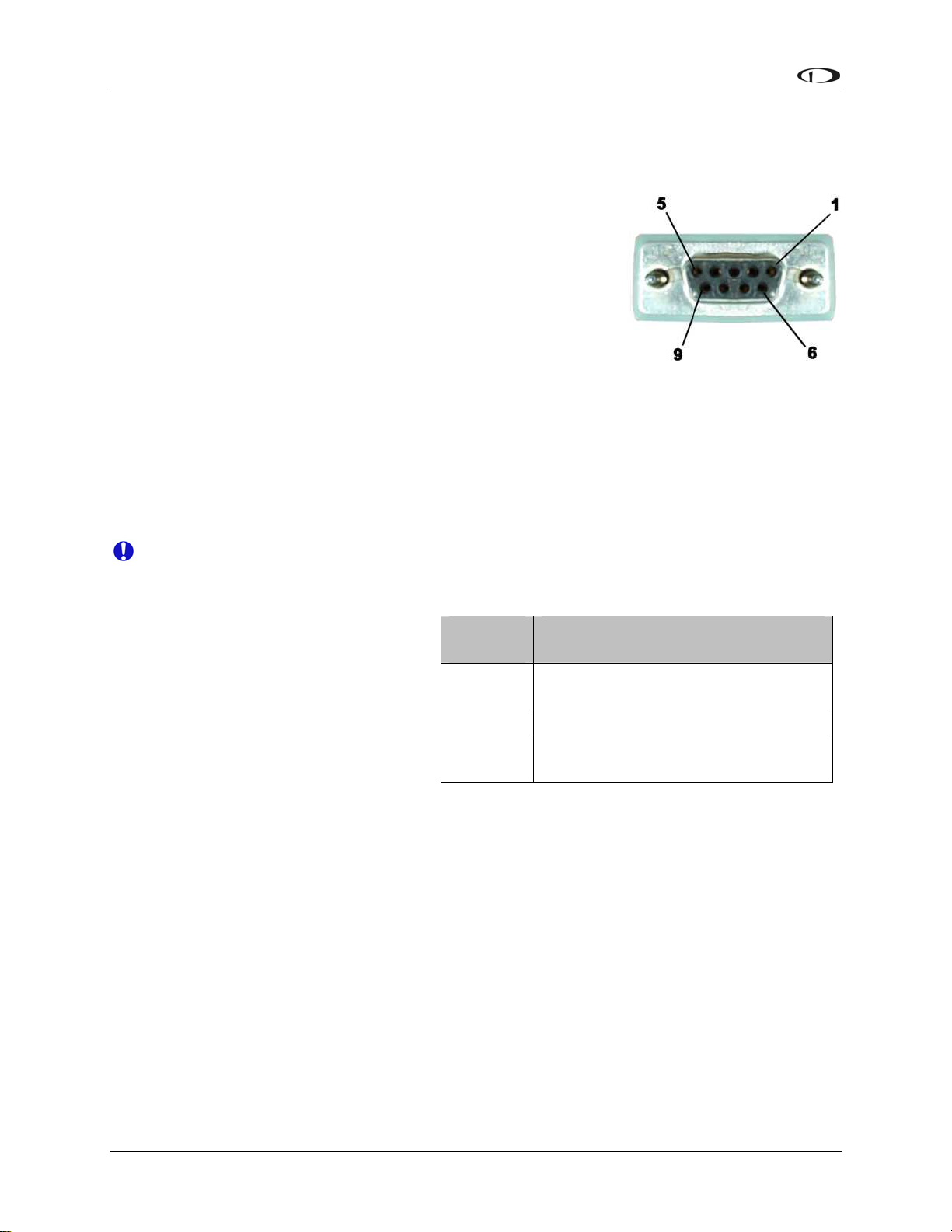
Appendix
Wiring Instructions.
Once you have physically mounted the OAT probe, route its
attached cable to the EDC-D10A remote magnetic compass
module. Your OAT comes with pins crimped on the 3 wires.
Insert these 3 wires’ pins to the following pin numbers on the D9
which plugs into the EDC-D10A. The front of the female
connector is pictured at right. You will be inserting the pins into
the back of this connector.
Pin 2: Yellow wire
Pin 7: Red wire
Pin 8: Blue wire
The exposed shield wires are not strictly required, but may help OAT performance in noisy
environments. If you wish to connect the shield to ground, you may splice it into the blue wire or
connect it to the EDC-D10A chassis.
You may lengthen or shorten the connections between the OAT and EDC-D10A. Use the
provided crimp connectors on the new wire leads.
Do not make connections while the EFIS-D10A is powered!
OAT/TAS/DA DISPLAY
You must set up the EFIS-D10A to
recognize the OAT. The EFIS-D10A
supports two different types of OATs as
well as a manual input of the outside
temperature. To set this up, enter the
menu system by pressing any button
beneath an EFIS page, and press MORE
> SETUP > MORE > OAT. Push the
INSTALLED button (either button 1 or
2) to toggle between N, 1 and 2. All OATs sold by Dynon since 2005 are P/N 100433-001, so
you most likely need to select sensor type 2.
Note: Set the OAT INSTALLED parameter to N when you either: a) do not have an OAT at all
or b) have an OAT connected to EMS D37 connector. If you do not have an OAT in the system
at all, the OAT info item will be surrounded by a box denoting that its value can be adjusted
manually.
To display the data from the OAT probe, press any button below an EFIS page to bring up the
EFIS menu and press MORE > INFO. Select the side of the screen that you wish to display
TAS/DA information on (LEFT or RIGHT). Push the button labeled OAT. The values for
outside air temperature, density altitude and true airspeed will be shown.
Installed
Type
N
1 Dynon P/N 100240-000
2
No OAT installed, dial in OAT value
Dynon P/N 100433-001– marked
with a black band near the sensor
Sensor
in OATSET menu
7-8 EFIS-D10A Installation Guide
Page 81

Appendix
CALIBRATION AND ADJUSTMENT
Before adjustment, it is possible for the OAT sensor to read as much as 5 degrees Celsius off the
actual value. Therefore, it may be necessary to adjust the displayed air temperature value to
compensate for this. To make this adjustment, you must enter the menu system and press the
following sequence of buttons: MORE > SETUP > MORE > OAT. This will display the OAT
adjustment menu. Press INC or DEC to increase or decrease the currently displayed OAT value.
It is important to make this adjustment when the air surrounding the OAT probe is at a known
temperature. This can be achieved with a standard thermometer. Adjust the displayed OAT until
it agrees with your independent temperature reference.
TROUBLESHOOTING
OAT value fluctuates wildly
If the OAT probe is improperly wired, the EFIS-D10A will not receive a valid signal from it.
Verify that the three wires coming from the OAT probe are wired exactly as described in the
Wiring Instructions section above.
OAT value is consistently high/low
You need to adjust the displayed OAT value to correct for sensor inaccuracies. Follow the
instructions in the Calibration and Adjustment section above.
OAT display area states OAT NOT FOUND
Ensure that you have selected the number corresponding to your OAT in the OAT INSTALLED
menu as described above. It can sometimes take as long as 5 seconds for the EFIS-D10A to lock
onto the OAT reading. Ensure that all wiring is correct and that there are no shorted or open
connections.
Other strange behavior by OAT reading
It is possible that your EFIS-D10A and EDC-D10A have mismatched versions of firmware on
them. This most commonly happens when one takes the EFIS-D10A out of the aircraft to
connect to a computer for firmware upgrade. Ensure that the EFIS-D10A and EDC-D10A are
connected to each other and communicating before attempting a firmware upgrade.
EFIS-D10A Installation Guide 7-9
Page 82

Appendix
Appendix C: HS34 Installation and Configuration
If you purchased an HS34 from Dynon Avionics, read through this section for details on its
physical and electrical installation. It describes the pinout, mounting information, and some
common wiring connections.
WIRING
Follow these instructions explicitly as improper wiring can result in permanent damage to your
instrument, other connected equipment, or both. Read through the Recommended Wiring
Practices section on page 2-1 before proceeding.
Harness Construction
Because the HS34 interfaces with such a wide variety of NAV radios and GPSs in different
combinations of configurations, Dynon Avionics does not supply pre-manufactured harnesses for
the HS34. Instead, your HS34 shipped with enough connectors and pins to generate a wide
variety of harness configurations. Refer to the Pinouts and Function Description and Common
Device Connections sections below for detailed wiring inform
If you do not own a D-sub machined-pin crimping tool, they can be obtained for under USD$50
at www.bandc.biz (P/N RCT-3), www.steinair.com (P/N SAT-004), and many other tool
retailers. You may also find it helpful to own a pin insertion/extraction tool, part numbers DSE-1
and SAT-023, respectively.
ation.
Power Requirements
22 AWG wire is normally sufficient for the power supply and
ground lines, but you should consult a wire sizing chart and
determine the size required for your routing length. Make sure you
protect the power lines with either a circuit breaker or an
appropriately sized fuse for the wire you select. Power is fed to the
HS34 via pins in the male DB25 connector on the back of the
instrument.
The HS34’s power requirement is 2 watts typical and 3 watts
maximum. On a 12-volt system, this translates to about 0.25 amps
of maximum current draw. On a 24-volt system, this translates to
about 0.13 amps maximum current draw. Normally, a 0.5-amp
circuit breaker or fuse is sufficient.
Connector Description
The HS34 has two DB25 connectors on the rear of the instrument:
one male and one female. All references to connector gender in
this guide are used to describe the connectors on the back of the
HS34, not your harnesses. When building harnesses for the HS34,
make note of the fact that the pin order for the male connector is the
opposite of the order for the female connector. Small pin numbers
can be found next to each pin on both the instrument’s and
harness’s connectors.
7-10 EFIS-D10A Installation Guide
Page 83

Appendix
Pinouts and Function Description
Below are the pinouts and function descriptions for the HS34’s male and female connectors. At a
mini n in the Universal Connections diagram. All mum, you must make the connections show
other wiring connections depend on the external equipment you are connecting to the HS34.
Many common radio and GPS connections are depicted in the Common Device Connections
section below. Note that the pin numbers are labeled on the face of both the female and male
connector.
Male (on HS34) DB25 Female (on HS34) DB25
Pin# Function Pin# Function
1
Serial 1 RX (PC updates & second
serial port)
1
CDI + when deflected right
2 Serial 2 RX (SL30, GPS, etc) 2 VOR + when TO flag shown
3 DSAB A 3 LOC +
4
5
6
aster Power (10-30V, 250 mA
max V)
imum at 12
GP Output 1 (not currently
supported)
GP Output 2 (not currently
supported)
4
5
6
GS + when up UP
GS + when FLAG shown
DME Analog IN (0-8V,
40mv/NM)
M
7 G P 1 in (same as EMS GP in) 7 Resolver G
8 GP 2 in ( S GP in) same as EM 8 Resolver D
9 +5V out 9 Resolver F
10
11
12
GP 6 in (+15V GP in, not currently
supported)
GP 5 in (+15V GP in, not currently
supported)
GP 4 in (+15V GP in, not currently
supported )
10
11
12
ARINC 429 RX 2 B
ARINC 429 RX 1 B
ARINC 429 TX B
13 GP 3 in (same as EMS GP in) 13 ARINC 429 TX B
14 Serial 1 TX 14 CDI + when Left
15 Serial 2 TX 15 VOR own + when From flag sh
16 DSAB B 16 LOC 17 Master Ground 17 GS + when Down
18 Contact in contacts) GS + when Flag hidden 4 ( Ssame as EM 18
19 Contact in contacts) 3 (same as EMS 19 Resolver C
20 Contact in 2 (same as EMS contacts) 20 Resolver H
21 Contact in 1 (same as EMS contacts) 21 Resolver E
22 Marker Outer Input 22 ARINC 429 RX 2 A
23 Marker Middle Input 23 ARINC 429 RX 1 A
24 Marker Inner Input 24 ARINC 429 TX A
25 Voice audio output (8V peak-peak) 25 ARINC 429 TX A
EFIS-D10A Installation Guide 7-11
Page 84

Appendix
Universal Conn
T llo ctions that must be ma
he fo wing diagram shows the wiring conne de in every HS34
ections
installation. These required connections ensure that the HS34 can power on, communicate with
other Dynon products, connect to a laptop for firmware uploads, and output audio alerts to your
intercom system. Once properly configured on your DSAB network, this connection sch
eme
allows you to use your HS34’s VALUE knob with the DSAB Bus Master. Refer to the Dynon
Smart Avionics Bus (DSAB) Wiring section on page 3-11 for more information on connecting
Dynon products via DSAB. Refer to the DSAB Configuration section on page 5-1 to review the
concepts involved in a networked system as well as an example system which includes an HS34
Again, the “Male D25” in the diagram below refers to the male connector on the back of the
HS34. The harness you construct to make these connections will terminate in a female D25
connector.
.
7-12 EFIS-D10A Installation Guide
Page 85

Appendix
Generic Device Connections
The three diagrams on this page depict generic device connections for devices outputting
ARINC, serial, or analog data. If your device outputs multiple types of data, connect only one
type to the HS34 in the following preference: ARINC preferred over serial; serial preferred over
analog. ARINC data streams contain more information (vertical GPS guidance, GPS steering,
etc) than serial streams and allow more control of your external device. Likewise, serial streams
contain more information than that carried over analog lines. If your device is one of those listed
in the next section, Common Device Connections, you may ignore this section. See page 3-4 for
a chart of supported GPSs.
EFIS-D10A Installation Guide 7-13
Page 86

Appendix
Common Device Connections
The following several diagrams show some common radios and GPSs, and the preferred
connection schemes between them and the HS34. Make note of whether the connections are to
the male or female connector on the back of the HS34. When constructing your harness, refer to
the pinouts on page 7-11.
7-14 EFIS-D10A Installation Guide
Page 87

Appendix
EFIS-D10A Installation Guide 7-15
Page 88

Appendix
7-16 EFIS-D10A Installation Guide
Page 89

AppendixAppendix
PANEL LOCATION AND MOUNTING
This section provides you with dimensions, panel location, and mounting information.
HS34 Dimensions and Panel Location
The diagram below shows the HS34’s outer dimensions. Note that the instrument extends about
3.7” behind the panel, and that harnesses can require up to three more inches. Use the
dimensions (in inches) found on the diagram to plan for the space required by the instrument.
The front bezel of the vertically oriented HS34 (100755-000) is the same height as Dynon’s
D100-series products and can be mounted close to – or abutted against – one if desired. Plan a
panel location that allows for convenient operation of the knobs and buttons. Ensure that the
instrument is in a location where the light sensor (small circle of rubber at upper left of
instrument) can measure the true ambient light conditions in the cabin.
EFIS-D10A Installation Guide 7-17 EFIS-D10A Installation Guide 7-17
Page 90

Appendix
Mounting Tab Dimensions
T tab are below. Note that the tab does not extend
he dimensions for the included mounting
behind the panel perpendicularly. This sharper angle causes the HS34 to pull itself again
st the
panel when screwed into the tab.
HS34 Mounting
As shown in diagram at right, make a rectangular cutout
– oriented either vertically or horizontally, depending on
HS34 version ordered – of 1.45” by 4.75” (3.69 cm by
12.07 cm). Drill three holes at the locations specified in
the diagram. Your HS34 also shipped with a life-sized
mounting template for making this cutout and drilling
the mounting tab holes. Secure the mounting tab to your
panel in whatever way you desire. Riveting it to the
panel is ideal, but drilling holes for mounting screws
and nuts also works.
Upon securing the mounting tab to the back of your
panel, slide the HS34 into it. Because the mounting tab
does not extend behind the panel perpendicularly, the
HS34 must slide into the panel such that only the top (or
right, for the horizontal version) of the bezel meets the
panel. The tapered mounting screw fits into the PEM
nut at the end of the mounting tab. Use the included
7/64” Allen wrench to secure the mounting screw into
the mounting tab. As you screw the mounting screw
tighter, the bottom (or left, for the horizontal version) of
the bezel moves closer to the panel. Once it touches the
panel, do not turn the mounting screw any further.
7-18 EFIS-D10A Installation Guide
Page 91

Appendix
HS34 CONFIGURATION
This section guides you through configuring your HS34. Prior to beginning this section, you
must have completed all the steps in the DSAB Configuration chapter with the HS34 turned on
and connected to the DSAB network. After DSAB configuration, ensure that the HS34 appears
as one of the ACTIVE devices in the EFIS > SETUP > DSAB > STATUS menu.
You may only configure your HS34 on the EFIS-based instrume
Master role. The following configuration steps are performed within th
nt assigned the DSAB Bus
e EFIS > SETUP > HSI
menu on the Bus Master instrument.
Device Communication Setup
If you have connected a NAV radio to the analog
diagram on page 7-13, enter the ANALOG menu to configure comm
Press SEL► to change the INPUT ENABLED to Y. The SYNC
pins shown in the Analog Connections
unication with this device.
H OFFSET parameter is used to
correct analog errors that can occur in the signal path between your radio and the HS34’s
measurement. You may normally leave SYNCH OFFSET set to 0. However, if you observe
errors in the green course pointer on the HSI Page, you – or a qualified avionics shop – may
modify this parameter to bring the course pointer into agreement with the NAV radio. Set
SYNCH OFFSET, in degrees, to a value equal to the number of degrees of error in the course
pointer on the HSI Page.
If you have connected one or two devices outputting serial d
SERIAL menu, and SEL► to enter it. If the device conne
is a GPS, set INPUT to either AVIATION or NMEA (dep
on your GPS), and OUTPUT to NONE. If the device co
SL30 Nav/Comm, set INPUT to SL30 and OUTPUT to S
Set the BAUD RATE parameter to match the baud r
devices support more than one type of data format an
ate us
d ba
BAUD RATE settings for SERIAL 1 agree with the settin
device connected to the HS34’s Serial 1 pins. If you have
ata, push DOWN▼ to select the
cted to the SERIAL 1 RX and TX pins
ending on the output format configured
nn
ected to the serial pins is a Garmin
L30 CMD.
ed by your SL30 or GPS. Many
ud rate; ensure that the INPUT and
gs in the communication setup for the
a second NAV radio or GPS connected
to the Serial 2 pins, repeat the above steps for it.
If you have connected
one or two devices outputting
the ARINC-429 menu, and SEL► to enter it. Set INP
ARINC-429 data, push DOWN▼ to select
UT1
HS34’s ARINC-429 RX 1 A and B inputs: GAMA GPS
connected a device to ARINC-429 RX 2 A and B, repe
at t
INPUT2 parameter; otherwise, leave it set to NONE. Nex
LOW), based on the output speed of your two ARINC d
channel with 2 sets of pins on the connector for wiring
ARINC devices can accept commands, set the OUTP
co
UT
SPEED appropriately.
Note that the EFIS/EMS SERIAL menu is disabled on all
with an HS34 connected. All GPS and NAV devices mus
EFIS-D10A Installation Guide
7-19
to the type of device connected to the
,
GAMA NAV, or DME. If you have
he above configuration for the
t set the SPEED parameter (HIGH or
ev
ices. The HS34 has one ARINC output
nvenience. If one or both of your
DATA to ON and configure OUTPUT
products connected to a DSAB system
t
be connected to the HS34.
Page 92

Appendix
Markers Configuration
The HS34 supports markers input via ARINC or the 3 discrete Inner, Middle, and Outer mark
er
pins.
If your NAV radio outputs ARINC data whose stream contains marker information, set the
SOURCE to either ARINC1 or ARINC2. ARINC1 corresponds to the ARINC-429
B inputs (fem
ale DB25, pins 11 and 23). ARINC2 corresponds to the ARINC-429 RX 2 A a
RX 1 A and
nd B
inputs (female DB25, pins 10 and 22). You must also ensure that the corresponding INPUT1 or
INPUT2 parameter in the ARINC-429
menu is set to GAMA NAV.
If you have a device which outputs marker data via 3 discrete signals, set the SOURCE to
MRKR PINS. Ensure that your device’s Outer, Middle, and Inner outputs are connected to the
HS34’s male DB25 pins 22, 23, and 24, respectively. Marker beacon receivers use a variety of
techniques to output the 3 marker signals. Because of this, you may need to experiment with the
PULL-UP and ACTIVE WHEN parameters. As a general rule of thumb, if the schematic for
your receiver shows the 3 discrete outputs connected to lights whose other side is connecte
power, set PULL-UP to Y and ACTIVE WHEN to LOW. Likewise, if the schematic shows th
discrete outputs connected to lights whose other side is connected to ground, set PULL-UP to
d to
e 3
N
and ACTIVE WHEN to HIGH.
Regardless the input type used, you can configure the HS34 to output tones for Outer (Morse
code “dashes”), Middle (Morse
code “dot-dashes”), and Inner (Morse code “dots”) markers. Set
TONES ACTIVE to Y to configure the HS34 to output the tones for each of the 3 markers. Set
to N to configure the HS34 to have no audible marker feedback.
it
DME Configuration
The HS34 supports Distance Measuring Equipment receiver input via
ARINC or the single DME
Analog In pin (female DB25, pin 6).
If you have connected a DME receiver which outputs ARINC data, set the SOURCE to either
ARINC1 or ARINC2. ARINC1 corresponds to the ARINC-429 RX 1 A and B inputs (female
DB25, pins 11 and 23). ARINC2 corresponds to the ARINC-429 RX 2 A and B inputs (female
DB25, pins 10 and 22). You must also ensure that
the corresponding INPUT1 or INPUT2
parameter in the ARINC-429 menu is set to DME.
If you have connected a DME receiver to the HS34’s DME Analog In pin, set the SOURCE to
DME PIN.
GPS and NAV Display Order Configuration
Pressing the NAV SRC button on the HS34 cycles through the available NAV sources in the
following order: DG, NAV1, NAV2, etc., GPS1, GPS2, etc. Of course, the numbers of NAVs
and GPSs in the cycle depend on how many of each type are configured in the ANALOG,
SERIAL, and ARINC-4
29 m
enus.
If you have configured more than one input to receive NAV radio data, enter the NAV ORDER
menu to see the list of configured NAV radios and the HS34 inputs they are connected
to. In this
menu, you may change the order that each NAV input occurs within the NAV portion of cycle. If
you do not see all expected NAV radios, verify that all settings are accurate in the ANALOG,
SERIAL, and ARINC-429 menus. Press DOWN▼ or UP▲ to select the input that you wish to
7-20 EFIS-D10A Installation Guide
Page 93

Appendix
occur first in the NAV portion. Press MV UP▲ until it appears next to NAV1:. Repeat this for
the input you wish to be assigned NAV2 in the source cycle, and so on for as many other NAV
radio inputs.
Repeat the above procedure for all configured GPS inputs in the GPS ORDER menu.
Voice/Tone Alert Configuration
The HS34 can act as the sole audio alert
source for all DSAB-connected Dynon
instruments. The HS34’s audio output
reports both EFIS and EMS alerts; each
type of alert can be configured to be either
voice or tone formats. When the HS34 is
connected to your system, audible alerts are
still generated by both EMS- and EFISbased instruments. If you would like the
HS34’s audio out to be your only source
for Dynon product audible alerts,
disconnect the audio out connect
ions on
your other DSAB-connected Dynon
products.
To configure HS34 audio alerts, enter the
EFIS > SETUP > HSI menu, scroll down to
AU d press SEL►. The
DIO ALERTS, an
following points describe the options
available for each setting:
EMS: EXT TONE / EXT VOICE – Sets
whether you want the HS34 to report tones
or voice alerts during EMS alarm
conditions. This setting has no effect on the
“direct” audio output of the EMS.
EFIS: EXT TONE / EXT VOICE – Sets
whether you want the HS34 to report tones
or voice ale
rts during EMS alarm
conditions. The “direct” audio output of the
EFIS is m
uted*.
EMS AUDIO ALERTS
RPM HIGH
MANIFOLD PRESSURE HIGH
OIL PRESSURE HIGH/LOW
OIL TEMPERATURE HIGH/LOW
EGT [1..6] HIGH/LOW
EGT SPAN
CHT [1..6] HIGH/LOW
CHT SPAN
CHT [1..6] SHOCK
FUEL LEVEL [1..4] LOW
FUEL PRESSURE HIGH/LOW
FUEL FLOW HIGH
VOLTAGE HIGH/LOW
CURRENT HIGH/LOW
COOLANT TEMPERATURE HIGH
COOLANT PRESSURE HIGH/LOW
All other EMS alerts vocalized “EMS ALERT”
EFIS AUDIO ALERTS
ALTITUDE (Altitude alerter)
CLIMB/DESCEND (Altitude alerter)
AUTOPILOT DISCONNECT
STALL
TIMER EXPIRED
DSAB ERROR
EFIS: EFIS TONE – tones are generated through the “direct” audio output of the EFIS and the
audio output of the HS34 is muted.
AOA: EXT TONE – During an AOA
alarm condition, tones are generated through the HS34
audio output and the EFIS “direct” audio output is muted*.
AOA: EXT VOICE – During an AOA alarm condition, voice is generated through the HS34
audio output simultaneously with a “progressive” tone from the EFIS “direct” audio output.
AOA: EFIS TONE – Tones are generated through the “direct” audio output of the EFIS and the
audio output of the HS34 is muted.
EFIS-D10A Installation Guide 7-21
Page 94

Appendix
* If an HS34 failure is detected during this condition, the EFIS “direct” audio output (tones only
is automatically re-enabled (fail-over).
Selecting TES) T VOICE OUTPUT and then pressing SEL► produces an audible voice test
(“DYNON AVIONICS”) on the audio output line. This allows you to verify connectio
volum
e on the ground.
ns and
The possible voice alerts for both EFIS and EMS are listed i
VALUE Knob Configuration
The VALUE knob changes the ALT an
d BARO settings P >
and is configured from HSI SETU
VALUE KNOB ►.
The VALUE knob can be configured to req
uire an init ny
ial push before rotating the knob has a
effect (REQUIRE PUSH: YES / NO).
The “default” mode of the VALUE knob
BARO to set Altimeter or Barometer mod
is configured by setting FIRST ACTION: ALT /
e, respectively.
If REQUIRE PUSH is set to YES:
The first push of the VALUE kno
and displays a “pop-up” wind
b within 5 seconds changes the value RO).
kno
A second push of the VALUE knob
the VALUE knob and closes the popknob push or knob rotation), the VAL
after 5 seconds and closes the pop-
If, after the first pus
h of the VALUE knob, the e
VALUE knob within 5 seconds ac
indicated by the mode displayed in th
b activates r BARO)
the FIRST ACTION mode (ALT o
ow indicati he
of the FIRST ACTION mode (ALT or BA
within 5 seconds a de-activates
up win
UE kn s out)
up
window.
dow. If there is no further action (either a
ob automatically de-activates (time
knob is not rotated, a second push of th
tivates
the secondary mode of the VALUE knob –
e pop-up windo
n the table above.
ent mode and value. Rotatinng the curr g t
fter rotating the knob
w.
Pushing the VALUE knob
windows described above) de-activat
a third time or after a knob rotation (within the 5 second
es the VA ow.
LUE knob and closes the pop-up wind
If REQUIRE PUSH is set to NO:
Rotating the VALUE knob changes t
BARO) and displays a pop-up windo
the VALUE knob again within 5 seco
he value of the FIRST ACTION mode (ALT or
w indicati
ng the current mode and value. Pushing
nds of the last knob rotation closes the pop-up
window.
Pushing the VALUE knob without first rotating it activates the secondary mode of the
VALUE knob (ALT or BARO, whichever was not chosen as FIRST ACTION) and
displays a pop-up window indicating the current mode and value. Pushing the VALUE
knob again within 5 seconds of the last knob rotation closes the pop-up window.
If there is no further action (either a knob push or knob rotation) within 5 seconds, the
pop-up window automatically closes.
7-22 EFIS-D10A Installation Guide
Page 95

Appendix
NAV and/or GPS Fail-over
While not required, it is possible to provide a NAV and/or GPS data fail-over capability in case
of a failure of the HS34. To accomplish this, the outputs of the NAV and/or GPS device can
connected in parallel to an EFIS or EMS and an HS34. While the HS34 is operating normally,
be
the NAV and/or GPS data connected to the HS34 is displayed. (Only) if the HS34 fails, the NAV
and/or GPS data connected to the EFIS and/or EMS is (temporarily) displayed. There is no
indication provided that the data being displayed is connected to the EFIS and/o
notification that the HS34
has failed.
r EMS – only a
To configure and test NAV and/or GPS failover:
1. Temporarily d
isconnect or power off the HS34 and reconfigure the system without the
HS34.
2. Connect and configure the NAV
and/or GPS outputs to the EFIS and/or EMS inputs.
Ensure that the NAV and/or GPS data is being properly displayed on the EFIS.
3. Reconnect the HS34 and reconfigure the system to
4. Connect and configure the (p
arallel) NAV and/or GPS ouputs to the HS34. Ensure that
recognize the HS34.
the NAV and/or GPS data is being properly displayed on the EFIS.
5.
To test the fail-over capability, temporarily disconnect the HS34 and observe the NAV
and/or GPS data on the EFIS; data should display properly after a pause of a few seconds
with the HS34 connected, and disconnected.
EFIS-D10A Installation Guide 7-23
Page 96

Appendix
Appendix D: Dynon AOA/Pitot Installation and Calibration
Thank you for your purchase of Dynon’s AOA/Pitot Probe. This guide walks you through the
steps to install and calibrate both the heated and unheated versions of the AOA/Pitot Probe.
While the probe senses standard pitot pressure, allowing it to work with any standard airspee
indicator, its AOA functionality is designed specifically to work with Dynon’s EFIS series of
products. Do not expect it to work prod perly with another AOA system.
To ensure accuracy, it is very important that you i
specified calibration steps. W
the
installation.
Dyn ’ he
on s Heated AOA/Pitot Probe is nickel-plated. Do not polish the probe as this will cause t
fini
sh to come off.
A
OA CALCULATION: PRINCIPLES OF OPERATION
Dyn
on Avionics’ AOA/Pitot probe performs two functions: airspeed sensing and angle of attack
sens g
in . These functions require two pressure ports on the tip of the probe. The normal pitot
pressure port is on th
The
second pressure port is located on an angled surface just under the pitot port and is designed
to be ve
pressur
HEATING: PRINCIPLES OF OPERATION
ry sensitive to AOA. The EFIS-D10A then uses the difference between these two
es to calculate the current angle of attack.
e front face of the probe and is designed to be insensitive to angle of attack.
e recommend that you read the entire guide before proceeding with
nstall the probe correctly and perform the
The heated version of Dynon’s AOA/Pitot Probe utilizes a heating mechanism unlike any other
heated pitot on the market. The probe is heated by a high-quality nichrome heating element
whose temperature is accurately measured and regulated by the heater controller. This controller
– located in an enclosure which can be mounted in a wing or elsewhere – regulates the heat at the
tip of the probe to a constant temperature. There are several advantages to this, including: lower
power consumption, increased heating element lifespan, and a much cooler pitot on the ground
when de-icing is not necessary. This unique technique ensures that the pitot can be rapidly deiced when required, but does not needlessly waste electricity when not in icing conditions.
While the probe does not operate like a normal heated pitot, it will still get fairly hot in normal
ambient temperatures. When turned on, it will regulate its internal temperature to about 70°C to
80°C. To ensure that the heater is working, briefly touch the end of the pitot farthest from the
snout after 1 minute of operation and verify that it is warm.
FAILURE WARNING
Designed to meet the indication requirements of FAR 23.1326, the heated pitot controller has an
output that can trigger a warning light in the cockpit whenever the probe heater is turned off or is
not functioning properly. While not required for Experimental and LSA category aircraft, this
feature provides peace of mind, giving you instant feedback that your probe’s heater is working
as designed.
7-24 EFIS-D10A Installation Guide
Page 97

Appendix
TOOLS AND MATERIALS REQUIRED
Dynon Avionics AOA/Pitot probe.
Two plumbing lines (usually ¼” soft aluminum or plastic tubing) routed from the EFIS-
D10A to the probe mounting location.
Tubing interface hardware
o Reference our wiki at wiki.dynonavionics.com for tubing interface hardware
recommendations.
#36 Drill and 6-32 tap
AOA Pitot M
ounting bracket. Models known to work well include:
o Gretz Aero CBK12 (Chrome) and PBK12 (Paintable), available at
aero.com/mountbracket.html
gretz or from Aircraft Spruce.
d lip for the RV series. It is available o SafeAir1 also makes a bracket with a joggle
from www.safeair1.com
.
Please follow these instructions explicitly as improper installation can result in permanent
damage to your device and/or aircraft.
HEATER CONTROLLER WIRING AND MOUNTING
If you have purchased the heated version of the probe, please follow the instructions in this
s rsion of the probe, you may skip to the AOA/Pitot
ection. If you have purchased the unheated ve
P ollow these instructions explicitly as improper
robe Mounting section on page 7-28. Please f
installation can result in permanent damage to your device and/or aircraft.
Heater Controller Mounting
The heater controller box should ideally be mounted close to the AOA/Pitot Probe. The box’s
dimensions are found at right, for
reference. When mounting the
controller close to the probe, ensure
that it is close enough for its wires to
mate with the probe’s wires, with
room for strain-relief. If you find it
difficult to mount the controller in
the wing, or simply wish for the
controller to be mounted closer to
th end the
e battery, you must ext
lines using the correct wire gauge as
described in the Wiring section
below.
When the desired location is
selected, secu
re the heater controller
via the 4 mounting holes. Route the
wiring between the probe, controller, panel, and power source, as described below.
EFIS-D10A Installation Guide 7-25
Page 98

Appendix
Heated AOA/Pitot Wiring System Overview
T basic layout of the electrical connections between the
he following block diagram depicts the
probe and heater controller. This diagram should be used in conjunction with detailed
in to
structions on the following pages. Read the specific instructions for each connection prior
inst
allation.
7-26 EFIS-D10A Installation Guide
Page 99
Appendix
Heater Controller Wiring
Before making the connections to your Heated
AOA/Pitot Probe and controller, refer to the
Recommended Wiring Practices section on page
2-1. The chart at right provides general
recommendations for wire gauge choice, given
wiring run length.
Probe to Controller Wiring
As mentioned above, it is preferable that the
heater controller box be mounted near enough to
the probe that 5 wires between the controller and
Recommended wire gauge for runs,
given 10-amp peak current
Run length Gauge
0’ – 7’ 18 AWG
7’ – 9’ 16 AWG
10’ – 16’ 14 AWG
17’ – 24’ 12 AWG
25’ – 40’ 10 AWG
From FAA AC 43.13-1B, page 11-30
probe can be connected without extension. The
three mating pairs of colored wires – terminated with Fastons – are used to carry the current to
the heating element in the probe. The 2 white wires are for temperature measurement, and can
thus be small. If you have mounted the heater controller near the probe and do not need to extend
the wires between the two, simply plug each wire on the controller into its corresponding likecolored wire from the probe.
If you do need to extend the wires between the probe and the controller, use the recommended
wire size (see chart on page 7-25) for your run length. Since extending the wire runs requires that
you cut the connectors off the 5 wires between the probe and controller, splice the extension
wires between the probe and controller using butt splices or other sim
ilarly secure method. The
white wires are not polarity-dependant. Additionally, as the white wires do not carry any
significant current, you may extend them with 26 AWG or larger for any run length.
Controller Power wiring
Three wires – colored red, black, and white
– exit the controller for connection to your
electrical system. Power (between 10 and
15 volts) is fed to the controller via the red
and black wires. The maximum current
draw of the heated pitot controller/probe is
10 amps. You must route your own
appropriately-sized wires to where the
heater controller is mounted. Both power
and ground lines should be able to handle
10 amps with minimal voltage drop, as
recommended in the chart on page 7-25.
The red wire should be connected through
a pilot-accessible switch to the main power
source in the aircraft (limited to 15 volts).
The switch allows you to manually turn the
heater controller on and off, depending on
the situation. Install a 15-amp fuse at any
point along the power line to the heater
Color Notes
Red Connected through a pilot-accessible
switch to 10–15V supply. Must handle
up to 10 amps.
Black Must have a constant connection to
ground. This is required for the warning
light to operate when controller is
powered off or not functioning. Line
must handle up to 10 amps.
White Connected to a light bulb (or resistor &
LED) tied to switched ship’s power.
This line is grounded when the heater
controller is powered off or not
functioning. Connection can handle no
more than 1 amp. Current depends on
light source connected.
EFIS-D10A Installation Guide 7-27
Page 100

Appendix
controller. Rem even when the controller is powered on, it only heats the probe the
ember that
amount necessary to maintain temperature.
The black wire should be permanently connected
controller should occur via the red power line, not
Heater Status Connection
Note: The probe he
ater functions properly whether or not yo his connection. It is simply
to gr
ound. Cutting power to the heater
the black
ground line.
u make t
a status output for your convenience.
The white heater status wire is grounded whe
properly. This wire should be connected to a light
connected to switched aircraft power. When the he
heater status line is open, leaving the indicator light tu
n the probe he ed o g
on the pa oth
a ite
ter is on and functioning properly, the wh
ater is turn ff or not functionin
nel, whose er terminal is
rned off. When there is no power to the
heater controller – or it is not functioning properly – the white line is grounded, turning the
indicator light on.
Aircraft Spruce P/N 17-410 is an example of a light that will work for this application. An LED
and resistor in series will also suffice. If you use an LED as the indicator, you must choose a
resistor that delivers the appro
priate current to the LED, and can accommodate the power
required for its current and voltage drop.
If you own a Dynon EMS-based product, you may also use one of its two contact input to
display an onscreen indication. Connect this heater status output directly to the desired EMS
contact input, with no additional resistors or lights. You must configure the contact display as
described in your EMS-based product’s Installation Guide.
AOA/PITOT PROBE MOUNTING
The Dynon Avionics AOA/Pitot probe has been designed as an under-wing pitot. The following
information applies to this type of installatio
mount, contact us so we can make the appro
of Dynon’s AOA/Pitot Probe does not com
AOA/Pitot Probe Mount Location
The Dynon Avionics AOA/Pitot probe only
where the airflow over the probe is r
elatively un d
recommend that you mount it at least 6
between 2 and 12 inches behind the leadin
mounted about mid-wing span wise to min
tips. Testing during the probe development has s
the pitot probe in the RV series of aircraft
AOA/Pitot Probe Mounting Instructions
After the mounting location has been determ
instructions or fabricate your own mount. In
such that the body of the probe is horizontal
32) on the probe to match your mounting br
that you avoid drilling into the pitot and A
n. If you wish to mount your pitot on nose boom
pria tments to your pitot. The heated version
te adjus
e n
a -i boom mount configuration.
func
tions correctly when mounted in a location
disturbe by the aircraft. In general, we
inches below the
g edge of the win
imize the effect
hown that the or
also w
orks for the Dynon probe.
ined, mo
eithe
r case, mount the probe securely to the wing
durin
g level flight. Drill and tap mounting holes (#6-
wing and with the tip of the probe
g. Typically, pitot probes are
s of both the propeller and the wing
standard mounting locations f
unt the pitot m
ounting kit per the include
acket. Use caution when drilling the holes, ensuring
OA pressure lines. As long as you do not penetrate
d
7-28 EFIS-D10A Installation Guide
 Loading...