

Page 1
EFIS-D10
Electronic Flight Information System
Pilot’s User Guide
Last Revised: 5/23/2005
Dynon Avionics
Page 2

Contact Information
Dynon Avionics, 19501 144th Ave NE, Suite C-500, Woodinville, WA 98072
Tel: (425) 402-0433
http://www.DynonAvionics.com
2003 Dynon Avionics. All rights reserving, no part of this manual may be reproduced, copied, transmitted,
disseminated or stored in any storage medium, for any purpose without the express written permission of Dynon
Avionics. Dynon Avionics hereby grants permission to download a single copy of this manual and of any revision to this
manual onto a hard drive or other electronic storage medium to be viewed for personal use, provided that such electronic
or printed copy of this manual or revision must contain the complete text of this copyright notice and provided further
that any unauthorized commercial distribution of this manual or any revision hereto is strict ly prohibited.
Information in this document is subject to change without notice. Dynon Avionics reserves the right to change or
improve its products and to make changes in the content without obligation to notify any person or organization of such
changes. Visi t the Dynon Avionics web site (www.DynonAvionics.com
) for current updates and supplemental
information concerning the use and operation of this and other Dynon Avionics products.
March 2003 Part No. 100005-000
ii
5/25/2005
Page 3

Limited Warranty
Dynon Avionics warrants this product to be free from defects in materials and workmanship for three years from date of
shipment, or two years from date of first flight, which ever is sooner. Dynon Avionics will, at its sole optio n, repair or
replace any components that fail in normal use. Such repairs or replacement will be made at no charge to the customer
for parts or labor. The customer is, however, responsible for any transportation cost. This warranty does not cover
failures due to abuse, misuse, accident, improper installation or unauthorized alteration or repairs.
THE WARRANTIES AND REMEDIES CONTAINED HEREIN ARE EXCLUSIVE, AND IN LIEU OF ALL OTHER
WARRANTIES EXPRESSED OR IMPLIED, INCLUDING ANY LIABILITY ARISING UNDER WARRANT Y OF
MERCHANTABILITY OR FITNESS FOR A PARTICULAR PURPOSE, STATUTORY OR OTHERWISE. THIS
WARRANTY GIVES YOU SPECIFIC LEGAL RIGHTS, WHICH MAY VARY FROM STATE TO STATE.
IN NO EVENT SHALL DYNON AVIONICS BE LIABLE FOR ANY INCIDENTAL, SPECIAL, INDIRECT OR
CONSEQUENTIAL DAMAGES, WHETHER RESULTING FROM THE USE, MISUSE OR INABILITY TO USE
THIS PRODUCT OR FROM DEFECTS IN THE PRODUCT. SOME STATES DO NOT ALLOW THE EXCLUSION
OF INCIDENTAL OR CONSEQUENTIAL DAMAGES, SO THE ABOVE LIMITATIONS MAY NOT APPLY T O
YOU.
For warranty i nformatio n please contact:
Dynon Avionics, Inc. 19501 144
PH: (425) 402-0433 FAX: (425) 984-1751
Dynon Avionics retains the exclusive right to repair or replace the unit or software or offer a full refund of the purchase
price at its sole discretion. SUCH REMEDY SHALL BE YOUR SOLE AND EXCLUSIVE REMEDY FOR ANY
BREACH OF WARRANTY.
th
Ave NE, C-500, Woodinville, WA 98072
5/25/2005
iii
Page 4

Table of Contents
Contact Information...................................................... ii
Limited Warranty.........................................................iii
Table of Contents......................................................... iv
Introduction 1
Welcome....................................................................... 1
About this manual......................................................... 2
Hardware Information 3
Main Unit...................................................................... 3
Internal Battery............................................................. 3
Quick Overview 5
Onscreen Elements ....................................................... 6
Horizon line, pitch and roll indicators.................. 7
Stabilized heading tape......................................... 7
Altitude digital readout......................................... 7
Altitude tape ......................................................... 7
Angle of attack (AOA) tape.................................. 8
Airspeed digital readout........................................ 8
Airspeed tape........................................................8
Bug display........................................................... 9
Turn coordinator................................................... 9
Clock/Timer.......................................................... 9
Menu system and User Interaction ............................. 10
iv
Menu Functions 11
Overview.....................................................................11
Main Menu Flow.................................................12
Operation.....................................................................13
POWER – Power on/off......................................13
BARO –Setting Barometer/ Altitude...................13
BUGS – Setting Bug Markers.............................14
CHKLST – Using Checklists..............................16
SETUP – Setting Preferences ..............................16
INFO – Informational Items................................20
DIM – Changing screen brightness.....................22
TIMER – Setting and using a timer.....................22
Appendix 24
Operating Tips.............................................................25
Serial Data Output....................................................... 26
Glossary.......................................................................29
Troubleshooting ..........................................................32
Unit Errors...........................................................32
Alert Messages....................................................34
PC/EFIS Interface ...............................................37
Service Details.............................................................38
Index............................................................................39
5/25/2005
Page 5

INTRODUCTION
Welcome
Thank you for purchasing the Dyno n Avionics EFIS-D10 Electronic Flight Infor mation System. This smal l device,
which fits into a standard 3 1/8 inch instrument panel hole, combines the full functionality of 10 instruments vital to the
small aircraft pilot. As you will discover, the EFIS is a powerful tool, useful in a variety of small aircraft, at a price that
small aircraft owners can afford.
Because of recent advances in solid-state sensor technology, electronic flight instrument prices have drastically dropped.
This allows us to create new instruments such as the EFIS-D10. Using solid-state gyros, magnetometers, and
accelerometers the EFIS-D10 gives you reliable and accurate information about your flying environment. Your current
altitude, airspeed, compass heading, vertical speed, pitch, and roll can all be displayed on one screen. Completel y
customizable, the EFIS-D10 allows you to display as much or as little in formation as you want, allowing you to tailor it
to your needs.
The latest version of this manual may be downloaded from our website at www.DynonAvionics.com
page, simply click the Documentation link under Products > EFIS-D10.
5/25/2005
. From the main
1
Page 6

About this manual
This guide serves dual purposes. The first is to help you set up and get acquainted with the EFIS-D10’s many functions.
The second is to give you quick and easy access to vital information.
It is strongly recommended that you read the entire manual before attempting to utilize the EFIS-D10 in an actual flying
situation. Additionally, we encourage you to spend time on the ground to familiarize yourself with the operation of the
unit. This can be achieved either by using the unit’s internal battery (which lasts a minimum of 2 hours on a full charge)
or by using the unit in your plane while the master switch power bus is switched on. Finally, we encourage you to keep
this manual in the plane with you at all times. This document has been designed to give you quick access to information
that might be needed in flight. CAUTION: in a flying situation, it is the pilot’s responsibility to use the product and the
manual prudently.
As you read through this manual, you may come across words that are not familiar to you or for which you would like to
know more about. The Glossary
associated with solid-state technology.
In the electronic (.PDF) version of t his manual, underlined words act as hyperlinks taking you to t he relevant sec tion in
the manual that the word refers to. Additionally, clicking on any of the sections listed in the Table of Contents
jump directly to that section.
on page 29 will help you to more fully understand the many technical terms that are
above will
2
5/25/2005
Page 7

HARDWARE INFORMATION
This section gives you a brief overview of the various hardware components of your EFIS-D10. Thi s section serve s as a
reference only and should not be used for diagnostic or reparative work. However, it will help you to familiarize yourself
with the inner workings of the unit. For detailed installation instructions, please refer to the EFIS-D10 Installation Guide.
Main Unit
• The display is a 450 nit LCD screen, much brighter than most laptop displays
• Attitude information is obtained from 3 solid-state
gyrometers and 3 solid-state accelerometers. Heading
information is obtained from 3 solid-state magnetometers. Airspeed, altitude and angle of attack are obtained
from three separate pressure transducers
.
• User interaction takes place via the 6 buttons along the bottom of the front panel of the unit. Feedback is given
via short text messages along the bottom of the screen.
Internal Battery
• The internal battery is an optional accessory to the EFIS-D10, allowing the unit to operate in the event of an
external power failure.
• The lithium ion battery is rechargeable and is managed by the EFIS-D10 whenever an external power source is
connected.
• Under normal conditions, the internal battery should have a voltage between 13 to 16.8 Volts. You will receive
a low battery warning when the voltage drops below 13 volts.
5/25/2005
3
Page 8

• When fully charged, the internal battery is rated for a minimum of 2 hours of normal operation with the EFIS-
D10.
4
5/25/2005
Page 9

QUICK OVERVIEW
This section is meant to give experienced pilots and technicians an easy way to get started with the EFIS-D10. However,
it is suggested that you read the entire manual and familiarize yourself with the EFIS-D10 before using it in flight. This
section assumes that you have completed the installation of the EFIS-D10 as d e scrib e d in the Installation Guide and
performed all relevant calibration routines. The section first takes you on a tour of the main onscreen elements. Then, it
gives you an overview of the menu system. For a more detailed look at the many functions of the menu system, refer to
the Menu Functions
section below this one.
5/25/2005
5
Page 10
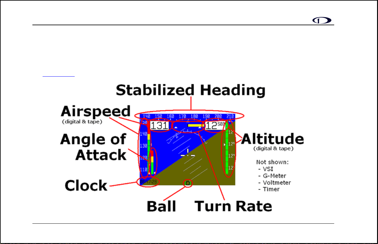
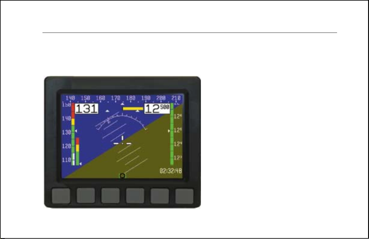
Onscreen Elements
This section will give you a quick look at every piece of information available to you onscreen. Below, you will find a
diagram showing you, at a glance, the default screen elements. Following that is a more detailed look at each item.
Additionally, some items, like the VSI and the G-meter, are not shown by default but are dealt with in the next section on
the menu system
.
6
5/25/2005
Page 11
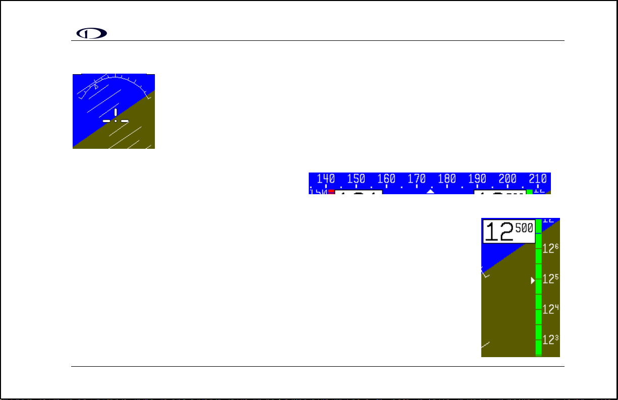
Horizon line, pitch and roll indicators
Bounded on the top by blue, and on the bottom by brown, the horizon line works in much the
same way that you would expect a traditional gyro-based artificial horizon to work. The notable
exception to this is the fact that it does not have a roll or pitch limitation in its d isp lay. The
division between blue and brown stays parallel to the actual horizon line re gardless of yo ur pitch
or roll. The parallel lines above and below the horizon line are the pitch indicator lines. Each line
represents 5 degrees of pitch. Similarly the arrow rotating around the roll indicator gives you an
idea as to the value of your roll. Each tic mark represents 10 degrees of roll.
Stabilized heading tape
This element functions much like a standard cockpit magnetic compass. The triangle alerts you to your current heading
allowing you t o quickly a scertain the value in degrees based on the surrounding values .
Altitude digital readout
The digital readout of your altitude, like the tape bar, displays thousands of feet using large
numbers and hundreds of feet using small numbers. Its proximity to the altitude bar will allow you
to quickly and easily associate the two screen elements. During the first 30 seconds of operation,
the altitude digital readout and tape will not be displayed as the unit needs a s mall amount of time
before altitude measurements are deemed accurate.
Altitude tape
The altitude tape bar gives you a visual representation of your altitude. The white triangle gives
you an analog view of your current altitude while the digital readout gives you a more precise
5/25/2005
7
Page 12
picture. Thousands of feet are displayed using large numbers while hundreds of feet are displayed in small numbers. As
mentioned above, the altitude tape will not be displayed during the first 30 seconds of operation.
Angle of attack (AOA) tape
The angle-of-attack tape indicates the aircraft’s current AOA relative to the stall AOA. The AOA calibration
process, described in the AOA/Pitot Installation Guide, will nominally result in the lowest angle-of-attack
stall (usually the “clean” configuration) occurring at the intersection of the yellow and red lines and the
higher angle-of-attack stall (usually the “dirty” configuration) occurring at the top of the red. To properly use
the AOA indicator, the pilot must keep in mind the present configuration of the aircraft and the corresponding stall
indication on the AOA tape. Please refer to the AOA/Pitot Installation Guide for more information.
Airspeed digital readout
In the upper left region of the display, you will find the digital readout of your current airspeed.
Like the altitude digital display, its numbers are the largest characters on the screen, giving you
quick access to important information as you scan the display.
Airspeed tape
The airspeed tape utilizes 4 colors to give you a graphical representation of your speed. By default
all of the color thresholds are set at 0, displaying a grey tape. You must utilize the EFIS-D10
Support Program on your PC to set the values of the airspeed color thresholds. Please see the Help
File for the EFIS-D10 Support Program for more information.
8
5/25/2005
Page 13
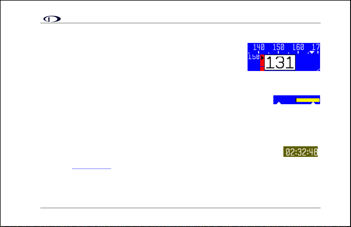
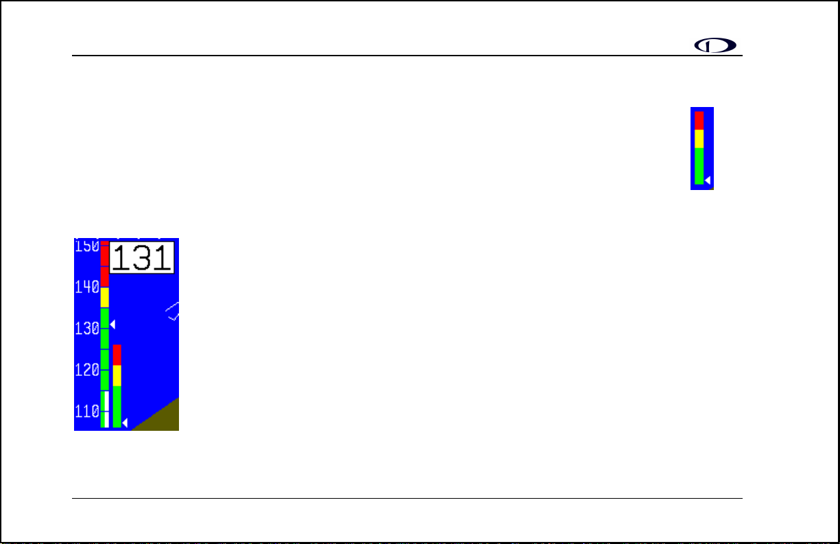
Bug display
Bugs may be set to mark a desired heading, airspeed or altitude. These bugs are
represented by a black (for airspeed and altitude) or white (for heading) arrow centered
in the appropriate moving bar at the desired location (see picture). If the set heading,
altitude or airspeed is currently not shown on its bar, the arrow appears at the edge of
the moving tape closest to the desired value. For example, in the picture, if the airspeed
bug is set at 160 knots, the arrow appears at the top of the bar pointing up past 150 knots, the highest displayed value.
This indicates that the pilot must increase his or her airspeed to reach the target airspeed.
Turn coordinator
Centered just below the heading moving tape, the turn coordinator provides real-time feedback of
the plane’s current yaw rate. The yellow bar grows in the direction that the plane is currently yawing. The yellow bar
grows to the right or left of a black vertical anchor line. The arrows on either side of the yellow bar’s anchor line point to
a place on the screen with which the yellow bar must line up for the plane to perform a standard rate turn. If the turn rate
is so great that the yellow bar exceeds the screen space between the airspeed and altitude digital displa ys, its length is
decreased by ½ and the standard turn rate arrows move closer to the black vertical anchor accordingly.
Clock/Timer
The clock is always displayed in the lower right-hand corner of the screen. All setting of the clock
occurs in the value setting box
count-up timer is enabled, it is displayed in place of the clock until the timer is stopped.
, which is visible in the center of the screen above the menu lines. When a count-down or
5/25/2005
9
Page 14

Menu system and User Interaction
The menu system for the EFIS-D10 is designed to provide
quick access to commonly used functions while taking up
a minimum amount of space on the screen. All user
interaction takes place via the 6 buttons at the bottom of
the front panel of the EFIS-D10. When no menu is
present, pressing any of the six buttons will bring the
main menu on the screen as shown at right. The six
sections of any menu correspond respectively to the six
buttons below them.
The overview
operating the me nu s yst e m. The operation
below gives you a guide to the basics of
section
provides a more detailed look at each of the functions that
can be accessed via the menu system.
10
5/25/2005
Page 15

MENU FUNCTIONS
Overview
The EFIS-D10 menu system is designed to be as unobtrusive and easy-to-navigate as possible. The following is a look at
the general operation of the menu system. After reading this section, you should be comfortable with basic navigation of
the menu system. The following few points will give you a basic understanding of the menu system, allowing you to
better understand the more in-depth Operation
flow.
• When no menus are displayed, pressing any button brings up Main Menu 1.
• The menu system operates as a hierarchy. When in any of the 2 main menus, pressing a button will show the
next level down in the hierarchy. For ease of navigation, a tab located just above the currently displayed menu
alerts you to the context of the menu.
• Button 6 (on the far right) is the universal “back-out” button.
o In either of the two main menus, it is labeled EXIT and will remove the menus from the screen
completely.
o In any other menu, it is labeled BACK and will display the menu above the current one in the
hierarchy.
• Aside from the two main menu lines, all menus have a tab directly above the left side of the menu line alerting
the user to the context of the menu. For example, when in the barometer setting menu, the text BARO is visible
in the tab above the left side of the displayed menu.
section below. On the following page is a look at the main menu level
5/25/2005
11
Page 16

• When changing values (barometer value, clock, timer, etc), pressing and holding either the INC or DEC button
to change values will cause the rate of change to increase.
• All text for buttons is limited to 6 characters to minimize the amount of screen space the menus take up. As a
result many words are abbreviated, such as MLITRY for military and BARO for barometer.
Main Menu Flow
There are only 2 main menus. The following diagram shows their basic flow. As with all other menus, pressing MORE
will show more options that are on the current hierarchical level.
12
5/25/2005
Page 17

Operation
This section will guide you through each of main menu selections and their sub-menus.
POWER – Power on/off
When the EFIS-D10 is turned off but still has a power
source via one of the three power inputs, pressing the far
left button will turn the unit on. Likewise, once the unit is
on and any button has been pressed, bringing up main menu
1, the leftmost button will turn the unit off. As can be seen in the picture above, this button is labeled POWER and must
be held for 2 seconds to turn the unit off. While power is still connected, the unit is never fully turned off. It simply
enters an extremely low-power state, allowing it to keep track of time and detect a change in state of the POWER button.
BARO –Setting Barometer/ Altitude
While in main menu 1, pressing button 2, labeled BARO,
displays the barometer/altitude set button. The last-set
barometer value, in units of inHg, is displayed in the valuesetting box beneath the BARO text label. The DEC and INC
buttons increment the barometer value by 1/100ths as
indicated by the highlighted text after the decimal place.
When the hundredths roll over the tenths digit will change accordingly. As you increment or decrement the barometer
value, you will see the altitude tape on the right and the digital display above change. Adjust the barometer until the
altitude indicators display the correct altitude for your location or the barometer matches the current barometric pressure
value as indicated by your nearest airport.
5/25/2005
13
Page 18

BUGS – Setting Bug Markers
You have the ability to set a “bug” on any or all of the
three tapes. The setting and toggling of heading, airspeed,
and altitude markers works essentially the same; however,
a description is provided for setting each bug. As can be
seen by the diagram, pressing the BUGS button displays
the BUGS submenu. From there, you may choose HDING,
AIRSPD, or ALTTUD.
Heading
To set a marker (bug) at a target heading press BUGS while in Main Menu 1. This will bring you to the BUGS submenu,
as seen above. Choosing the HDING option will bring you to the HDING submenu.
Pressing the TOGGLE button will toggle the currently set heading bug display on the horizontal heading bar. A white
arrow located on the heading tape at the target heading represents the bug. Upon entry into the Heading Bug menu the
Set Value dialog box is displayed in the lower center of the display. Press SEL to select which di git to change and
buttons 4 (DEC) and 5 (INC) to decrease and increase each digit’s value respectively.
As you increment or decrement the heading bug value it will rollover at 360 degrees, returning the value to 0. If you have
the bug toggled on, you will see the arrow move left or right across the heading bar as you decrement or increment its
value.
Airspeed
To set a marker (bug) at a target airspeed, press BUGS
(button 3) while in Main Menu 1. This will bring you to the
14
5/25/2005
Page 19

bugs submenu as seen in the diagram. Choosing the AIRSPD option will bring you to the following menu.
Pressing the TOGGLE button will toggle the currently set airspeed bug display on the vertical airspeed bar. A black
arrow located on the tape at the target airspeed represents the bug. Upon entry into the Airspeed Bug menu the Set Value
dialog box is displayed in the lower center of the display. Press SEL to select which digit to change and buttons 4 (DEC)
and 5 (INC) to decrease and increase each digit’s value respectively.
As you increment or decrement the airspeed bug value it will stop on the low end at 0 and 300 knots on the upper end. If
you have the bug toggled on, you will see the arrow move up or down across the airspeed bar as you increment or
decrement its value.
Altitude
To set a marker (bug) at a target altitude press BUGS
(button 3) while in Main Menu 1. This will bring you to the
bugs submenu (see below). Choosing the ALTTUD option
will bring you to the fol lowing menu.
Pressing the TOGGLE button will toggle the currently set altitude bug display on the vertical altitude bar. A black arrow
located on the altitude tape at the target altitude represents the bug. Upon entry into the Altitude Bug menu the Set Value
dialog box is displayed in the lower center of the display. Press SEL to select which digit to change and buttons 4 (DEC)
and 5 (INC) to decrease and increase each digit’s value respectively.
As you increment or decrement the altitude bug value it will stop on the low end at -1200 ft and 30,000 ft at the upper
end. If you have the bug toggled on, you will see the arrow move up or down the altitude bar as you increment or
decrement its value.
5/25/2005
15
Page 20

CHKLST – Using Checklists
In the current release of EFIS-D10 software, you are limited to 5 checklists each containing 14 lines of text per checklist.
40 characters can fit on each line of the screen. To load checklists onto your EFIS-D10, you must use upload them as
described in the help file that comes with the EFIS-D10 Support Program. You must also have an RS232 serial port
attached to the EFIS-D10 which allows for upload of new software. Pushing the CHKLST button will take you to the
checklist submenu which will contain the checklist titles as defined b y you durin g the setup process with the PC. You
may customize the checklists and their titles as you wish. CAUTION: Once you select one of the checklists, the entire
screen is covered up by it. Do not select a checklist unless you do not actively need to view the display of the EFIS-
D10.
SETUP – Setting Preferences
In main menu 2, press the SETUP button to display the
menu where configuration preferences may be set. In this
submenu, you have 5 options to choose from. Each of these
options is explained in more detail below.
Zero pitch
Frequently, pilots find that the normal cruise attitude for
their plane does not correspond to an absolute zero pitch.
This comes as a result of many factors including plane
design and current weight load during a given flight. To
accommodate this fact, you may “zero” the currently displayed pitch of the EFIS-D10. The best way to do this is to
adjust the displayed pitch once you are flying straight and level and can observe that a non-zero pitch is displayed. From
the SETUP submenu, press the PITCH button. This will display the pitch adjust submenu. From there, simply increment
(INC) or decrement (DEC) the displayed pitch until the screen shows a zero pitch. This value is remembered by the unit
16
5/25/2005
Page 21

and used on all subsequent flights. Ke ep in mind that you must change it back if you inte nd for the sett ing to be only
temporary due to an unusual weight load, for example.
Change displayed units
In the UNITS submenu, you will see two toggles for
Airspeed and Altitude units. The current release of EFISD10 software supports airspeed units of Knots and
Miles/Hour and altitude units of only feet. Future versions
will support more options than these. To change airspeed units between knots and mph simply press either button 2 or
button 3, which corresponds to the AIRSPD: label. As mentioned, the only option for altitude units is Feet, thus you are
not able to toggle this value.
Set the clock
From the SETUP submenu, press the CLOCK button. This
will display the clock-setting submenu. In the value-setti ng
box, you will see a section for the local time and a section
for Zulu time. Because local time is usually an offset in
hours from Zulu time, when you set the minutes for local
time, you will see the minutes for Zulu time change.
However, you need to set the hours for local and Zulu times
independent ly. Once you have set Z ulu time, you should
never need to change it, as it is independent of daylight
saving time . To change the local cl ock for moving through
time zones or to enter da ylight saving time, simply change
5/25/2005
17
Page 22

only the hours for the local time. Be aware that connecting to the EFIS-D10 with the Support Program will reset the
time; therefore, do not set the time until you have performed all of the PC interface operations. To set the time, simply
follow these guidelines:
• Set both the local and Zulu times in military time. This is to eliminate confusion durin g the clock setting process.
You have the option, as described below in the Clock Format section, to display the time in either military or
standard 12-hour format.
• Only the highlighted digits will be affected by increments or decrements.
• SEL moves the highlight t o the next set of digits. The order of selection is 1. Local ho urs, 2. Local minutes, 3. Zulu
hours. When Zulu hours ar e selected, pressing SEL will again highlight Local hours.
• DEC and INC decrement and increment the selected set of digits one at a time. To speed up the process, press and
hold the desired button. if you pass the desired value, you may simply back down to it by pressing the button
corresponding to the opposite direction.
• Incrementing or decrementing the minutes digits resets the second count, allowing you to set the clock down to the
second if you so desire.
Change clock format
Although you always set the clock in military time, you have the option to display it in either military or standard time.
Additionally, if you desire, you may display either local or Zulu time in the lower right corner of the screen. To set these
options, press the FORMAT button from the CLOCK submenu. This will displa y the FO RMAT submenu as seen in the
picture above. In this submenu, you toggle between local and Zulu time display by pressing either button 1 or button 2.
The status text following the colon shows the current status of the LOC/ZU toggle. To toggle between standard and
military time display, press either button 3 or button 4. Again, the status text following the colon shows the current status
of the 12/24 toggle.
18
5/25/2005
Page 23

Show/hide display items
From the SETUP submenu, press button 5
corresponding to CLUTTR. The Clutter Menu will
appear with the first four options. Each option
corresponds to an item on the screen that can be turned
on and off. As with all other menu items, these options
are abbreviated to commands containing 6 letters or
fewer. Four toggle options are listed per menu line.
Pressing a button corresponding to one of these four
options will turn the respective onscreen item on or off,
depending o n i ts current st ate. The first four options
are: ALTBAR (altitude moving tape), ALTDIG
(altitude digital readout), ASPBAR (airspeed moving
tape), and ASPDIG (airspeed digital readout). By
pressing button 5, corresponding to MORE on the menu
readout, four more choices are presented. These are COMPSS (moving heading tape), LATBAL (lateral acceleration
ball), TURNRT (turn rate indicator), and AOABAR (angle of attack tape). Pressing button 5, corresponding to MORE,
will display a third menu of items that can be toggled on and off. These are CLOCK (clock and time zone information),
ROLARW (roll angle indicator), and HORIZN (blue/brown horizon indicator). Pressing MORE will display the first set
of items again. The menu flow is presented in the diagram.
Check software version
The softwar e version submenu gives you two important
pieces of information: the version of EFIS-D10 software
that your unit is currently running and the number of hours
5/25/2005
19
Page 24

the EFIS-D10 has been on. From the second line (press MORE) of the SETUP submenu, press the VRSION button; this
brings up the software version submenu. T his s ubmenu will also display the amount of hours o f on-time the unit has had.
Aside from the BACK button, there is no user interaction in this submenu. It is simply for informational purposes. If you
should have need for technical support or other assistance from Dynon, please have your software version ready when
you call or write.
Perform magnetic calibration
Pressing the MAGCAL button will bring you to the magnetic calibratio n menu. To learn more about this function, please
refer to the Installation Guide.
INFO – Informational Items
The informational display items submenu is reac hed from
main menu 2 as shown in the diagram. From within this
menu, you have the option to display up to two of the three
options at a time. As can be seen by the INFO submenu,
you may display one of the three items on the upper left of
the screen and one on the upper right of the screen. More
detail about each of the three items is given below.
Voltmeter
The voltmeter displays 3 rows of information corresponding to the three power inputs on the EFIS-D10. The first row,
labeled M, displays the Master Switch voltage. The second row, labeled E, displays your optional external backup
battery voltage. The third row, labeled I, displays the EFIS-D10 internal battery voltage. If any of the 3 voltage inputs are
not present, 0.0V will be displayed for the respective voltage values. The letter V follows all three values, denotin g the
20
5/25/2005
Page 25

fact that voltages are being displayed. The EFIS-D10 will alert you when the internal battery is low by displaying a low
battery alert (see Errors and Warnings
below).
G-meter
The g-meter displays the current vertical acceleration experienced by the EFIS-D10
measured in G’s, where 1 G is the amount of force due to the earth’s field experienced by
an object at sea level. Positive g-force is defined as upward vertical acceleration, making
you feel heavier. Negative g-force is defined as downward vertical acceleration, making
you feel lighter. As can be seen in the picture, there are three rows of text that make up the g-meter. The top row, labeled
MX, is the maximum positive g-force experienced by the EFIS-D10 since reset. The middle row, labeled CR, is the
current g-force experienced by the EFIS-D10. The bottom row, labeled MN, is the minimum g-force experienced by the
EFIS-D10 since reset. This last value can be viewed as the maximum negative g-force experienced by the EFIS-D10.
To reset the max and min g-force values to the current g-force value, simply enter the INFO submenu and push the
RSET G button.
VSI (Rate of Climb)
The vertical speed indicator (VSI) consists of a single line with your current rate of climb or descent. If you are currently
gaining altitude, an up arrow is displayed to the right of the vertical speed value. If you are losing altitude, a down arrow
is displayed to the right of the vertical speed value. The units of VSI are feet/minute.
OAT (Outside Air Temperature)
If you have installed the optional OAT/TAS/DA sensor, the OAT function pro vides you with the current outside air
temperature, true airspeed, and density altitude. The temperature is given in degrees C, the altitude in feet, and the
airspeed in knots. For more information on the OAT function, please refer to the OAT installation and calibration guide
that came with your sensor.
5/25/2005
21
Page 26

DIM – Changing screen brightness
From main menu 2, press the DIM button, which causes the
brightness control sub menu to appear. Pressing BRITR will
increase screen brightness until it reaches its maximum. Pressing DRKR will decrease screen brightness until it reaches
its minimum. It is not possible to turn the screen completely black via this menu to prevent confusion between a dimmed
state and a turned-off state.
TIMER – Setting and using a timer
To access the timer, navigate to Main Menu 2, and press the
TIMER button. This will take you to the Timer menu seen
in the diagram.
In the value setting box, you will see either UP TIMER or
DN TIMER with the current timer value below. The
following points will assist you as you work with the timer.
• The UP/DN button toggles the menu and timer
between an up timer and a down timer. When
switching to an up timer, the timer set value resets,
allowing the up timer to count up from 0:00:00.
• To reset the timer, press the UP/DN button twice. This will bring you back to the same state (i.e. UP or DOWN
TIMER) that you were in before.
22
5/25/2005
Page 27

• To start the timer, press START. Once started, the button’s labe l changes to STOP. To stop the timer, press
STOP.
• You may not have an up timer and a down timer running at the same time.
5/25/2005
23
Page 28

APPENDIX
This appendix contains information not covered in the main section of the manual. Here you will find useful reference
tools such as a specifications sheet, operating tips, and a glossary. This section also contains details regarding the EFISD10 warranty and service.
24
5/25/2005
Page 29

Operating Tips
• If the outside temperature is below -30°C, let the unit run for at least 10 minutes before using it in flight. You
may see a TEMPERATURE OUT OF SPEC warning on the screen during this time. While this warning is
present, unit accuracy may be degraded. Waiting until the warning turns off will ensure that the unit has enough
time to heat itself up to a temperature at which the sensors will be accurate.
• The static pressure sensor is sensitive to high rates of temperature change as is usua lly seen during the first few
minutes of unit operation. As a result, more accurate altitude measurements will be obtained if you wait for
about 5 minutes before setting the barometer to give a correct starting altitude.
• During the first few minutes of a cold boot-up (i.e. the unit is turned on after having been off for at least 2
hours), the TEMPERATURE UNSTABLE warning may appear onscreen and the horizon will turn from
blue/brown to grey/black, alerting you to the possible inaccuracy of the unit’s altitude measurements.
5/25/2005
25
Page 30

Serial Data Output
The EFIS-D10 outputs text data through its serial port constantly during normal operation. This data is useful for a
variety of applications. All numbers are in decimal and are standard ASCII. To view the data using a terminal program,
the following settings should be used:
Baud rate: 115200
Data: 8 bit
Parity: none
Stop: 1 bit
Flow control : none
The format for the data being sent out the RS232 port is:
Char Width Description Notes
1 2 Hour 00 to 23, current hour according to EFIS-D10A’s internal clock
3 2 Minute 00 to 59, current minute according to EFIS-D10A’s internal clock
5 2 Second 00 to 59, current second according to EFIS-D10A’s internal clock
7 2 Fractions 00 to 63, counter for 1/64 second. Data output frequency.
9 1 Pitch Sign ‘+’ or ‘-’ (positive means plane is pitched up)
10 3 Pitch 000 to 900, pitch up or down from level flight in 1/10 degrees (900 =
26
90
o
)
5/25/2005
Page 31

Char Width Description Notes
13 1 Roll Sign ‘+’ or ‘-’ (positive means plane is banked right)
14 4 Roll 0000 to 1800, roll left or right from level flight in 1/10 degrees (1800
= 180
o
)
18 3 Yaw 000 to 359 in degrees (000 = North, 090 = East, 180 = South, 270 =
West)
21 4 Airspeed 0000 to 9999, airspeed in units of 1/10 m/s (1555 = 155.5 m/s)
25 1 Altitude Sign ‘+’ or ‘-’ (positive means altitude is above sea-level)
26 4 Altitude 0000 to 9999, altitude in units of meters
30 1 Turn Rate
‘+’ or ‘-’ (positive means plane is turning right)
Sign
31 3 Turn Rate 000 to 999, 1/10 degrees/second rate of yaw change
34 1 Lateral G’s
Sign
‘+’ or ‘-’ (positive means plane is experiencing leftward lateral
acceleration)
35 2 Lateral G’s 00 to 99, lateral G’s in units of 1/10 G (99 = 9.9 G’s)
37 1 Vertical G’s
Sign
5/25/2005
‘+’ or ‘-’ (positive means plane is experiencing upward vertical
acceleration)
27
Page 32

Char Width Description Notes
38 2 Vertical G’s 00 to 99, vertical G’s in units of 1/10 G (99 = 9.9 G’s)
40 2 Angle of
00 to 99, percentage of stall angle.
Attack
42 6 Status
An internal-use status bitmask containing 24 bits
Bitmask
48 2 Product ID Ascii-hex Dynon product ID: 01=EFIS-D10A, 10=EFIS-D10,
03=EMS-D10
50 2 Checksum The ascii-hex 2 byte sum of all 49 preceding bytes
52 2 CR/LF Carriage Return, Linefeed = 0x13, 0x10
As an example, the following is what one line of serial data looks like:
00082119+058-00541301200+9141+011-01+1500
This serial data can be logged using any standard serial terminal program such as Hyper Terminal. It can then be parsed
into its respective columns by many spreadsheet programs including Microsoft Excel.
28
3EA0C701A4<CR><LF>
5/25/2005
Page 33

Glossary
Accelerometer
Analog
Angle Of
Attack
Attitude
Digital
Gyro
Heading
Magnetic field
sensor
5/25/2005
We use accelerometers in the EFIS-D10 to measure the acceleration of the aircraft, which is an
important factor in determining the pitch and attitude of the aircraft. The accelerometers used in the
EFIS-D10 are solid state Micro-electromechanical Systems or MEMS accelerometers.
Describes signals that can have an infinite number of values. All of the EFIS-D10’s transducers
sample analog values such as the earth’s magnetic force, acceleration, and pressure.
The acute angle between the chord of an airfoil and a line representing the undisturbed relative
airflow.
The rotational status of the unit with respect to the surface of the earth, displayed on the main screen
using an artificial horizon line.
Describes signals that have discreet values. Much of the EFIS-D10 is based on digital technology.
This means tha t analog value s that are brought in by the various transducers are converted into a
digital format to be read and interpreted by the onboard microprocessors
The EFIS-D10 uses solid-state rate gyros to measure the rate of rotation around each of X, Y, and Z
axes. These provide to the attitude equation information about turn rates and the y are integ rated to
provide position information.
The line of path along which the unit moves with respect to the earth’s magnetic north pole,
measured in degrees.
The EFIS-D10 uses magnetic field sensors as a three dimensional electronic compass. The onboard
circuitry uses these sensors to resolve the earth’s magnetic field. With this information the device can
29
Page 34

calculate and display compass heading independent of attitude.
Nit
Pressure
transducer
Sleep Mode
Solid-state
Standby Mode
Transducer
TFT display
30
A unit of illuminative brightness equal to one candle per square meter, measured perpendicular to the
rays of the source. The EFIS-D10’s LCD screen is rated at 450 nits. For comparison, laptop screens
usually are rated at about 250 to 300 nits.
The EFIS-D10 uses three pressure transducers to measure the altitude, airspeed, and angle of attack.
The altitude pressure transducer measures the absolute pressure of the static port which is used in
calculating the barometric-based altitude. The airspeed and angle of attack pressure transducers are
differential pressure transducers that measure their respective ports verses the static port in order to
calculate airspeed and angle of attack.
The state that the unit enters when powered off via the POWER button. It does not completely power
off, but simply enters a very-low-power state monitoring battery voltages and keeping track of time.
Describes silicon transistor-based technology. The advantage of solid-state technology is that it
requires no moving parts and thus has fewer susceptibilities to mechanical failure.
When in standby mode, the EFIS-D10 does not display anything on the screen. It consumes only
enough power to run the internal clock and charge the internal backup battery. To exit standby mode
and resume normal operation, press any one of the 6 menu keys.
A sensor that converts a non-electrical value, such as acceleration or rotation rate, into a voltage,
which can be read by a microprocessor. The transducers on the EFIS-D10 are what allow it to
correctly display, attitude, heading, airspeed and altitude data.
The Thin Film Transistor display is the most obvious and visible part of the EFIS-D10. Its
technology is the same as that of standard flat-panel PC displays. The model that the EFIS-D10 uses
5/25/2005
Page 35

has a brightness rating of 450 nits with exceptional contrast, meaning it is sunlight-readable.
Value Setting
Box
VSI
5/25/2005
A box that appears near the bottom of the screen when the user is performing any kind of
manipulation of a value. This includes setting a bug, setting the barometer, and adjusting the clock.
Vertical Speed Indicator.
31
Page 36

Troubleshooting
Unit Errors
Problem Solution
After performing a magnetic calibration the EFISD10’s headi ng is wrong by a constant amount.
When the barometer on the unit is set correctly,
the displayed altitude is wrong by a constant
amount.
32
Orient your plane in a known direction, preferably on a compass
rose at the airport. Navigate to the Heading Adjustment menu by
pressing SETUP -> MORE -> MAGADJ. Increment or decrement
the value of the heading until the EFIS-D10 heading corresponds to
the direction in which your plane is pointed.
Set the barometer to the correct value for your current location and
altitude. Note the difference between the displayed altitude and the
actual altitude for your location. Navigate to the Altitude
Adjustment menu by pressing SETUP -> MORE -> ALTADJ.
Increment or decrement the value of the altitude until the EFIS-D10
altitude corresponds to that of the current location of your plane.
See diagram below for more information.
5/25/2005
Page 37

The unit blinks a blue screen continuously when
on.
5/25/2005
Ensure that your power supply is capable of supplying at least 1
amp and that it is at least 10 Volts.
If, after verifying that you have met these two conditions the unit
does not op erate normally, it may be necessary to contact Dynon
Avionics.
33
Page 38

Alert Messages
The following table describes the error/warning messages that the EFIS-D10 could display. The meaning of the message
is given here as well as information about when the error message conditions will go away.
Warning Message Meaning End condition
INTERNAL
BATTERY LOW
TEMPERATURE
OUT OF SPEC
34
You will see this alert only when operating
the unit solely off the internal backup battery.
When its voltage has dropped below a certain
threshold, you will see this alert.
Additionally, the voltmeter will be displayed
onscreen. When you see this alert, it is
advisable that you turn the unit off by
pressing the POWER button in Main Menu 1.
You will see this alert when the ambient
temperature sensed by the unit is below -30ºC
or above 50ºC. The sensors in the unit have a
certain temperature range within which they
are specified to operate normally. If they
operate outside this temperature range, the
attitude result can be compromised.
Therefore, the horizon indication will turn
from blue/brown to grey/black to indicate the
potential unreliability of the sensors while
outside the specified temperature range.
The alert will disappear when you press any
button; however, it is advised that you do not
ignore this alert, as it appears when the unit’s
internal battery has very little life left. This
alert will also go away upon the application
of either the external backup battery or master
switch power. At that point, the battery will
begin charging off the external power.
The text portion of the alert will disappear
when you press any of the buttons. However,
the horizon will not display blue/brown until
the unit senses temperature within its
specified range. If ambient temperature is
above 50ºC, the unit will always display the
horizon as grey/black. However, if ambient is
below 30ºC, it is possible that the unit will
heat itself up enough to operate normally.
5/25/2005
Page 39

TEMPERATURE
UNSTABLE
When the unit is turned on after having been
off for a long period, its internal temperature
will rise above ambient at a fast rate. This fast
change in temperature can sometimes reduce
the reliability of the output of the sensors.
Therefore, this alert is displayed and the
horizon ind i cation is changed from
blue/brown to grey/black.
The alert will disappear when you press any
of the buttons. The screen will remain grey
and black until the temperature within the unit
has stabilized. This temperature instability
should last no longer than 2 minutes. For this
reason, it is a good idea to turn the unit on
before you run through any of the preflight
procedures, so that it will be ready by the
time you are ready to fly.
ATTITUDE
INDETERMINATE
You will see this alert anytime the unit is
rotated at a rate faster than 150
degrees/second. Rotating the unit faster than
this threshold will saturate the gyros, leading
to potentially erroneous display. The
blue/brown horizon indication will turn grey
and black to indicate the fact that the artificial
horizon cannot be trusted.
TIMER EXPIRE This alert appears when you have a down
timer enabled and it has reached 0.
Additionally, as mentioned in the Timer
section above, the up timer menu will display
and the timer will flash the timer, alerting you
that the down timer has expired.
5/25/2005
Pressing any button will remove the text of
the alert. However, the horizon indication will
remain grey/black until the unit has resumed
normal operation. Once an indeterminate
attitude is detected, the unit enters a fast
recovery mode and usually recovers within 30
seconds.
Pressing any button will remove the alert and
stop the timer from flashing. However, you
must press STOP in the Up Timer menu to
stop the up timer. This allows you to see how
much time has elapsed since the down timer
has expired.
35
Page 40

HOLD FOR 2 SECS This alert appears when you have pressed the
POWER button in Main Menu 1. If the button
is held for 2 seconds, the unit will turn off.
Releasing the POWER button will cause the
alert to disappear and the unit will continue
normal operation.
POWER OFF 30
SECS.
36
This alert appears when master switch power
has been switched off but either the internal
or the external emergency batteries are still
connected. If no button is pressed within 30
seconds of when the alert appears, the unit
turns off. The voltmeter also appears onscreen
to show you the currently measured battery
voltages
If any button is pressed, the alert will
disappear and the unit will stay on. This will
cause the unit to continue full operation on
battery power. Remember that the internal
battery is rated for a minimum of 2 hours
when fully charged. If no button is pressed
within 30 seconds, the unit will turn itself off,
entering extremely low power mode.
5/25/2005
Page 41

PC/EFIS Interface
Please refer to the EFIS-D10 Support Program help-file by pressing the Help button in the program main window. Please
download the latest version of the EFIS-D10 Support Program from our website at
http://www.DynonAvionics.com/downloads
5/25/2005
37
Page 42

Service Details
Should you experience difficulty with your product, please contact us by one of two methods. If you have a computer
with an internet connection, point your browser to http://www.DynonAvionics.com/support.htm
giving every detail about the circumstances of the equipment failure. A customer service representative will contact you
regarding your probl em. Alternatively, if you do not have an internet connectio n, you may call or write to us at our
published phone or address giving us a detailed description of your problem.
, and fill out the form
38
5/25/2005
Page 43

Index
accelerometers....................................................1, 3, 29
altitude1, 3, 7, 8, 9, 13, 14, 15, 17, 19, 21, 25, 27, 30, 32
barometer...................................... 11, 12, 13, 25, 31, 32
battery
external backup.......................................................20
internal................................................................3, 20
master switch power............................ 2, 3, 20, 34, 36
bugs ............................................................ 9, 14, 15, 31
calibration......................................................... 5, 20, 32
checklist......................................................................16
clock ................................... 9, 12, 17, 18, 19, 26, 30, 31
G-meter................................................................... 6, 21
gyro............................................................................... 7
heading ................................... 1, 7, 9, 14, 19, 29, 30, 32
5/25/2005
horizon............................................7, 19, 25, 29, 34, 35
Installation Guide......................................................3, 5
main menu.....................................10, 11, 13, 16, 20, 22
menu system..................................................5, 6, 10, 11
pitch ........................................................1, 7, 16, 26, 29
power ..........................................................................13
roll.................................................................1, 7, 19, 26
Serial Data...................................................................26
software version..........................................................19
temperature .................................................................25
timer......................................................9, 12, 22, 23, 35
turn coordinator.............................................................9
voltmeter.........................................................20, 34, 36
VSI................................................................1, 6, 21, 31
39
 Loading...