

Page 1
Autopilot Servo Installation Guide
CAPSTAN
THIS PRODUCT IS NOT APPROVED FOR INSTALLATION IN TYPE CERTIFICATED AIRCRAFT
DOCUMENT 101385-000, REVISION D
January, 2013
Copyright © 2009-2012 by Dynon Avionics, Inc.
Permission to print this this manual is granted to third parties
Page 2

DYNON AVIONICS
Contact Information
Dynon Avionics, Inc.
19825 141st Place NE
Woodinville, WA 98072
Phone: (425) 402-0433 - 8:00 AM – 5:00 PM (Pacific Time) Monday – Friday
Dynon Technical Support available 7:00 AM–4:00 PM (Pacific Time) Monday – Friday
Email: support@dynonavionics.com
Fax: (425) 984-1751
Dynon Avionics offers online sales, extensive support, and frequently updated information on its products via its
Internet sites:
www.dynonavionics.com –Dynon Avionics primary web site; including:
docs.dynonavionics.com – Current and archival documentation, including installation guides.
downloads.dynonavionics.com – Software downloads.
support.dynonavionics.com – Support resources.
store.dynonavionics.com – Dynon’s secure online store for purchasing all Dynon products 24 hours a day.
wiki.dynonavionics.com – Dynon’s Documentation Wiki provides enhanced, extended, frequently updated online
documentation contributed by Dynon employees and customers.
forum.dynonavionics.com – Dynon’s Internet forum where Dynon customers can interact with each other and
Dynon Avionics. A key feature of the forum is that it allows the exchange of diagrams, photos, and other types of
files.
newsletter.dynonavionics.com – Dynon’s email newsletter.
blog.dynonavionics.com – Dynon’s blog where you can find new and interesting Dynon-related content.
register.dynonavionics.com – Register your Dynon Avionics product.
license.dynonavionics.com – Redeem certificates for navigation mapping software, synthetic vision, and other
features for license codes that add new functionality to your SkyView system.
Copyright
2008-2012 Dynon Avionics, Inc. All rights reserved. No part of this manual may be reproduced, copied, transmitted, disseminated or stored in
any storage medium, for any purpose without the express written permission of Dynon Avionics. Dynon Avionics hereby grants permission to
download a single copy of this manual and of any revision to this manual onto a hard drive or other electronic storage medium to be viewed for
personal use, provided that such electronic or printed copy of this manual or revision must contain the complete text of this copyright notice
and provided further that any unauthorized commercial distribution of this manual or any revision hereto is strictly prohibited.
Information in this document is subject to change without notice. Dynon Avionics reserves the right to change or improve its products and to
make changes in the content without obligation to notify any person or organization of such changes. Visit the Dynon Avionics website
(www.dynonavionics.com) for current updates and supplemental information concerning the use and operation of this and other Dynon
Avionics products.
Capstan Servo Kit – Installation Instructions 1
101385-000 Rev D
Page 3
DYNON AVIONICS
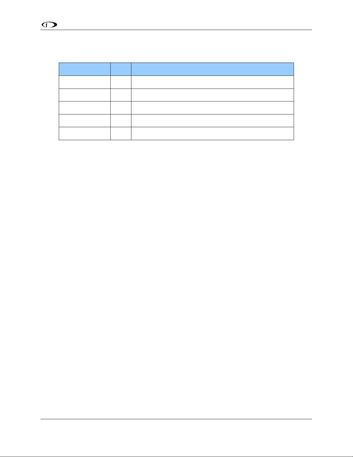
Dynon Part #
QTY
Part Description
100976-011
4
AN365-1032A Lock Nuts
100977-000
8
AN970-3 Large Washers
100981-003
4
AN3H-6A Bolts - 3/4"
101056-000
4
Cable Clamps
101113-000
1
Bridle Cable Assembly
CAPSTAN SERVO KIT – INSTALLATION INSTRUCTIONS
The capstan servo accessory kit includes the hardware necessary to attach one autopilot servo to one
axis of the aircraft controls. This kit can be used in either pitch or roll applications that utilize
pulley/cable driven controls (not suitable for use in pushrod linkage systems). Additional fasteners
(not supplied by Dynon) will be required to mount the servo in the aircraft.
When installing the servo, you must first determine a mount location for proper interaction with the
existing control system. This spot must allow the servo capstan to line up with the existing control
cables such that the provided bridle cable can be attached at each end using the nylon clamps and
ample room is available for the necessary motion of the system. The servo should also be mounted
as close to the control cable as possible to reduce the angle between it and the bridle cable, but not
so close as to rub during full range of control movement.
Once a suitable mounting location has been determined, the next step is to fabricate a bracket for
the servo. Refer to the included servo dimensions below. We recommend that 4 AN3H-3A bolts be
installed with MS35333-39 star washers (not provided). The 4 holes in the servo enclosure are fully
threaded to facilitate ease of mounting from the top, bottom, or a combination of both. If necessary,
removal of the capstan pulley and cable guard is permitted during fabrication of, and mounting into,
a bracket. Remove and discard the cotter pin and unscrew the castle nut. Remove the wave washer,
nylon washer, and finally the capstan pulley. Take care not to interfere with the installed shear
screw, as it cannot be removed without damage. The provided cable guard screws are long
enough to accommodate the cable guard being installed on top of a maximum of 1/16” bracket
material. More than this will push the heads of the screw up to an elevation that will interfere with
the reinstalled pulley. Do not reinstall with different screws as they may protrude into the
servo enclosure and damage internal components. If the drive cable is not parallel to the servo,
you may clock the cable guard to an orientation which allows the bridle cable to exit as required.
Torque the #6-32 cable guard screws back to 8 in-lbs and reinstall the rest of the parts as they were
removed. Torque the castle nut to 4.5 in-lbs, install and trim a new cotter pin.
Before final installation of the servo, assemble the capstan kit by removing the zip tie and unlooping
the bridle cable. Remove the heat shrink from both ends of the cable. Locate the swage nest hole in
the capstan pulley. The servo may need to be rotated to expose the hole if it is underneath one of
the flanges of the installed cable guard. Do not bend the flanges of the cable guard away from the
servo pulley; they are designed to keep the bridle cable from jumping grooves. Once the hole is
located, pass one end of the cable underneath one of the cable guard flanges so that the cable will sit
Capstan Servo Kit – Installation Instructions 2
101385-000 Rev D
Page 4

DYNON AVIONICS
in the center groove. Set the cable swage into the hole in the pulley and pass the other end of the
bridle cable under the opposite flange. Feed both cable ends around the pulley and underneath the
next set of cable guard flanges following the grooves.
With the cable properly fed into the pulley, install the servo in the mount. Rotate the capstan until
the installed swage sits on the opposite side of the pulley from where the bridle cable exits the servo
(see figure 1). Set the control stick to neutral and then install the cable clamps using the provided
AN3H-6A bolts, AN970-3 washers, and AN365-1032A lock nuts (see figure 2). The grooves in the
cable clamps are designed to work with the provided bridle cable diameter of 1/16” (small groove)
and aircraft control cable diameter of 1/8” (large grooves). The bridle cable should be taught and
have approximately 1” of cable protruding from the ends of the clamps. Torque them to 35 in-lbs to
provide the appropriate clamp force on the cables.
Figure 1 Figure 2
See figure 3 for an alternative configuration, with the two ends of the bridle cable exiting the pulley
in the same direction on opposite sides of the pulley. In this configuration the ends of the bridle
Capstan Servo Kit – Installation Instructions 3
101385-000 Rev D
Page 5

DYNON AVIONICS
Neglecting to properly install and/or use Dynon autopilot hardware may
result in failures which could cause loss of aircraft control resulting in
aircraft damage, personal injury or death.
cable would be attached to separate cables in the primary control system; ie the "up" and "down"
cables for the elevator, or the "left" and "right" cables for the aileronNote: the swaged index pin on
the bridle cable should be positioned in the center of the pulley between the two bridle cables as
they exit the pulley.
This second configuration is suitable for connection to elevator and aileron systems which function
as "closed loops" in which it is not possible for any cable in the control linkage to experience slack
in normal operation.
Figure 3
This configuration ***WOULD NOT*** be suitable for connection to a rudder cable system in
which deflection of the rudder by the pilot could result in slack in any of the primary control cables
or the attached bridle cable.
With the cable clamps attached, move the control stick fully in both directions several times. The
servo action should translate to smooth and consistent feel at the control stick with no binding or
rubbing. If there seems to be excessive friction, cable slop, or the cables have jumped a groove or
fallen off the edge of the pulley, it must be reinstalled in a location that provides a better angle for
interaction with the aircraft cable. Also verify the cable clamps do not come in contact with anything
during full travel. The built-in control stops of the aircraft will limit the servo capstan rotation when
installed correctly. It should never rotate more than 150 degrees in either direction from neutral.
For the latest documentation for all Dynon products (also available at dynonavionics.com). Please
read through that documentation to understand the wiring and configuration process for your
Autopilot system. We also maintain a collaborative set of this documentation, which is often
updated with new information by both Dynon and fellow builders. Visit wiki.dynonavionics.com to
view and contribute to the latest version of these documents.
You can also visit forum.dynonavionics.com to discuss and share installation notes, pictures, and
suggestions with other builders.
Capstan Servo Kit – Installation Instructions 4
101385-000 Rev D
Page 6

DYNON AVIONICS
Red
Black
Green
Blue
Yellow
Wht/Grn
Wht/Blu
Servo 1
Wires
Pilot-accessible
Servo Power
Switch/Breaker
Aircraft GND
Red
Black
Green
Blue
Yellow
Wht/Grn
Wht/Blu
Servo 2
Wires
Aircraft GND
Aircraft Power (10-30V)
Pitch and Roll Servos
are wired identically, and can
share wiring for convenience at
any point along the run.
5 kohm
Optional resistor for
detecting broken
disengage lines
Pilot-accessible
Disengage/CWS button
(Normally open, momentary)
Usually mounted to the stick
Power (10-30V)
Ground
SkyView Network 1 A or DSAB A
SkyView Network 1 B or DSAB B
Disengage
SkyView Network Data 2 A *
SkyView Network Data 2 B *
Power (10-30V)
Ground
SkyView Network 1 A or DSAB A
SkyView Network 1 B or DSAB B
Disengage
SkyView Network Data 2 A *
SkyView Network Data 2 B *
Servo Current Draw at 12V
(halve the current values for 24V systems)
SV32
Powered but disengaged: 0.1 amps
Engaged and holding, 100% torque: 0.80 amps
Engaged and moving, 100% torque: 1.33 amps
SV42
Powered but disengaged: 0.1 amps
Engaged and holding, 100% torque: 1.11 amps
Engaged and moving, 100% torque: 2.03 amps
SV52
Powered but disengaged: 0.1 amps
Engaged and holding, 100% torque: 1.52 amps
Engaged and moving, 100% torque: 2.80 amps
Aircraft GND
Use 22 AWG wire for SkyNet
and Disengage signals.
Use appropriate wire gauge for
servo power based on current
consumption and length of wire run
Green
Blue
Twisted Pair
Twisted Pair
Twisted Pair
D10A/D100/D180
D25
CONNECTOR
SKYVIEW
D9
CONNECTOR
N/A
N/A
5
4
4
8
6
1
WHT/BLU
WHT/GRN
BLU
GRN
Wht/Grn
Wht/Blu
*NOT USED FOR D10A/D100/D180
Wiring Overview
The following diagram provides an overview of the autopilot-specific wiring installation. For the
complete set of wiring and configuration instructions, please see the latest Installation Guide for
your Dynon EFIS product. For a SkyView system please reference the Autopilot Servo
Installation, Configuration, and Calibration chapter of your SkyView System Installation guide.
For EFIS-D10A, EFIS-D100 or FlightDEK-D180 please reference the Autopilot Installation and
Configuration chapter of each respective Installation Guide.
Capstan Servo Kit – Installation Instructions 5
101385-000 Rev D
Page 7

DYNON AVIONICS
Servo Dimensions
Use the following dimensions (in inches) for reference when planning and implementing your
installation.
Capstan Servo Kit – Installation Instructions 6
101385-000 Rev D
Page 8

DYNON AVIONICS
The autopilot safety shear screw should NEVER be removed or adjusted during this
operation. If the shear screw has broken and needs replacement, there is specific
documentation available for this purpose at http://docs.dynonavionics.com.
Capstan Servo Kit – Installation Instructions 7
101385-000 Rev D
 Loading...