

Page 1

Wireless Enhanced G Router
Routeur sans fil G amélioré
Enrutador inalámbrico G mejorado
DX-WEGRTR
USER GUIDE
GUIDE DE L’UTILISATEUR • GUÍA DEL USUARIO
Page 2

2
Dynex DX-WEGRTR
Wireless Enhanced G Router
Contents
Introduction ......................................................................................2
Product features ................................................................................3
Setting up your wireless router..........................................................9
Troubleshooting ..............................................................................47
Legal notices ...................................................................................58
One year limited warranty...............................................................61
Français ...................................................63
Español..................................................131
Introduction
Thank you for purchasing the Dynex DX-WEGRTR Wireless Enhanced G Router. The easy
installation and setup will have you networking wirelessly in minutes. Be sure to read
through this User Guide completely, and pay special attention to the section entitled
“Placement of your router for optimal performance” on page 47.
Contents
Benefits of a home network
Your home network will let you:
• Share one high-speed Internet connection with all the computers in your home
• Share resources, such as files, and hard drives among all the connected computers in
your home
• Share a single printer with the entire family
• Share documents, music, video, and digital pictures
• Store, retrieve, and copy files from one computer to another
• Simultaneously play games online, check Internet e-mail, and chat
Page 3

Product features
Advantages of a wireless network
Here are some of the advantages of setting up a Dynex wireless network:
• Mobility–you will no longer need a dedicated “computer room”— now you can work
on a networked laptop or desktop computer anywhere within your wireless range
• Easy installation–Dynex Easy Installation Wizard makes setup simple
• Flexibility–set up and access printers, computers, and other networking devices from
anywhere in your home
• Easy expansion–the wide range of Dynex networking products lets you expand your
network to include devices such as printers and gaming consoles
• No cabling required–you can spare the expense and hassle of retrofitting Ethernet
cabling throughout the home or office
• Widespread industry acceptance–choose from a wide range of interoperable
networking products
Product features
In minutes you will be able to share your Internet connection and network your computers.
The following is a list of features that make your new Dynex wireless enhanced G router an
ideal solution for your home or small office network.
Works with Both PCs and Mac® Computers—The router supports a variety of
networking environments including Mac OS®, X v10.x, Linux®, Windows® 2000, XP, Vista™,
and others. All that is needed is an Internet browser and a network adapter that supports
TCP/IP (the standard language of the Internet).
Front-Panel LED Display—Lighted LEDs on the front of the router indicate which
functions are in operation. You'll know at-a-glance whether your router is connected to the
Internet. This feature eliminates the need for advanced software and status-monitoring
procedures.
Web-Based Advanced User Interface—You can set up the router's advanced functions
easily through your web browser, without having to install additional software onto the
computer. There are no disks to install or keep track of and you can make changes and
perform setup functions from any computer on the network quickly and easily.
NAT IP Address Sharing—Your router employs Network Address Translation (NAT) to share
the single IP address assigned to you by your Internet Service Provider while saving the cost
of adding IP addresses to your Internet service account.
SPI Firewall—Your router is equipped with a firewall that will protect your network from a
wide array of common hacker attacks including IP Spoofing, Land Attack, Ping of Death
(PoD), Denial of Service (DoS), IP with zero length, Smurf Attack, TCP Null Scan, SYN flood,
UDP flooding, Tear Drop Attack, ICMP defect, RIP defect, and fragment flooding.
Integrated 10/100 4-Port Switch—The router has a built-in, 4-port network switch to
allow your wired computers to share printers, data and MP3 files, digital photos, and much
more. The switch features automatic detection so it will adjust to the speed of connected
devices. The switch will transfer data between computers and the Internet simultaneously
without interrupting or consuming resources.
3
Page 4

4
Product features
Universal Plug-and-Play (UPnP) Compatibility—UPnP (Universal Plug-and-Play) is a
technology that offers seamless operation of voice messaging, video messaging, games, and
other applications that are UPnP-compliant.
Support for VPN Pass-Through—If you connect to your office network from home using
a VPN connection, your router will allow your VPN-equipped computer to pass through the
router and to your office network.
Built-In Dynamic Host Configuration Protocol (DHCP)—Built-In Dynamic Host
Configuration Protocol (DHCP) on-board makes for the easiest possible connection of a
network. The DHCP server will assign IP addresses to each computer automatically so there is
no need for a complicated networking setup.
Easy Install Wizard—The Easy Install Wizard takes the guesswork out of setting up your
router. This automatic software determines your network settings for you and sets up the
router for connection to your Internet Service Provider (ISP). In a matter of minutes, your
wireless router will be up and running on the Internet.
Note: Easy Install Wizard software is compatible with Windows 2000, XP, Vista, and Mac OS
Mac OSx 10.4.x. If you are using another operating system, the wireless router can be set
up using the Alternate Setup Method described in this User Guide (see Alternate setup
method on page 15.
Enhanced G Mode*–Enhanced G Mode, a 54g performance enhancement, provides the
fastest wireless connectivity for 802.11g-capable networks in real-world environments. It is
designed for home networks that require additional bandwidth for applications such as
sharing digital pictures. Enhanced G makes 802.11g WLANs more efficient without affecting
the performance of neighboring networks, and is compatible at high speeds with leading
brands.
*When operating in 125 Enhanced G Mode, this Wi-Fi device achieves an actual throughput
of up to 34.1 Mbps, which is the equivalent throughput of a system following 802.11g
protocol and operating at a signaling rate of 125 Mbps. Actual throughput will vary
depending on environmental, operational, and other factors.
Integrated 802.11g Wireless Access Point—802.11g is an exciting new wireless
technology that achieves data rates up to 54 Mbps, nearly five times faster than 802.11b.
MAC Address Filtering—For added security, you can set up a list of MAC addresses (unique
client identifiers) that are allowed access to your network. Every computer has its own MAC
address. Simply enter these MAC addresses into a list using the Web-Based Advanced User
Interface and you can control access to your network.
Package contents
• Dynex Wireless Enhanced G Router
• Quick Installation Guide
• Installation software CD
• RJ-45 Ethernet cable
• Power supply
•User Guide
Page 5

Product features
System requirements
• Broadband Internet connection such as a cable or DSL modem with RJ45 (Ethernet)
connection
• At least one computer with an installed network interface adapter
• TCP/IP networking protocol installed on each computer
• RJ-45 Ethernet networking cable
• Internet browser
Easy Install Wizard Software System Requirements
• A PC running Windows 2000, XP, or Vista, or a Mac computer running Mac OSx 10.4x
• A minimum 64 MB RAM
• An Internet browser
5
Page 6
6
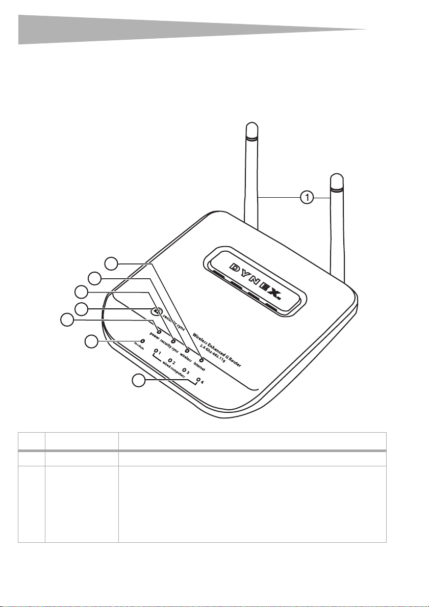
Components
The router has been designed to be placed on a desktop. All of the cables exit from the rear of
the router for better organization and utility. The LED indicators are easily visible on the front
of the router to provide you with information about network activity and status.
Front panel
4
3
2
Product features
6
5
7
8
# Component Description
1 Antennas Lets the router communicate with a wireless client (card or USB adapter).
2 Power/ready LED When you apply power to the router or restart it, a short period of time elapses while
the router boots up. During this time, the Power/Ready LED blinks. When the Router
has completely booted up, the Power/Ready LED becomes a SOLID light, indicating
the router is ready for use.
Off—Router is off
Blinking Green—Router is booting up
Solid Green—Router is ready
Page 7

Product features
# Component Description
3 Security Sync button Push and hold this button for three seconds, then initiate the Security Sync (WPS)
procedure on the client device within two minutes. Your client will automatically
exchange the security information and be added to your wireless network. Pushing
the Security Sync button will automatically enable WPS. See “Using Security Sync
(Wi-Fi Protected Setup)” on page 28.
4 Security Sync LED Lights to indicate that WPS has been activated.
4 Wireless network LED Off—The wireless network is off
5 Internet LED This unique LED shows you when the router is connected to the Internet. When the
6 Modem status LED This LED lights green to indicate that your modem is connected properly to the
7 Wired computer
status LEDs
Blinking Green—The router is searching for a WPS client to connect with.
Solid Green—The secure connection has been established with the client.
Solid Green—The wireless network is ready
Blinking Green—Network activity
light is OFF, the router is not connected to the Internet. When the light is blinking,
the router is attempting to connect to the Internet. When the light is solid green, the
router is connected to the Internet. When using the “Disconnect after x minutes”
feature, this LED becomes extremely useful in monitoring the status of your router's
connection.
Off—Router is not connected to the Internet
Blinking Green—Router is attempting to connect to the Internet
Solid Green—Router is connected to the Internet
router. It blinks rapidly when information is being sent over the port between the
router and the modem.
Off—No WAN link
Solid Green—Good WAN link
Blinking Green—WAN activity
These LEDs are labeled 1-4 and correspond to the numbered ports on the rear of the
router. When a computer is properly connected to one of the wired computer ports
on the rear of the router, the LED will light. green means a 10Base-T device is
connected, orange means a 100Base-T device is connected. When information is
being sent over the port, the LED blinks rapidly.
Off—The wireless network is off
Solid Green—A 10base-T device is connected
Solid Orange—A 100base-T device is connected
Blinking—Port activity
7
Page 8
8
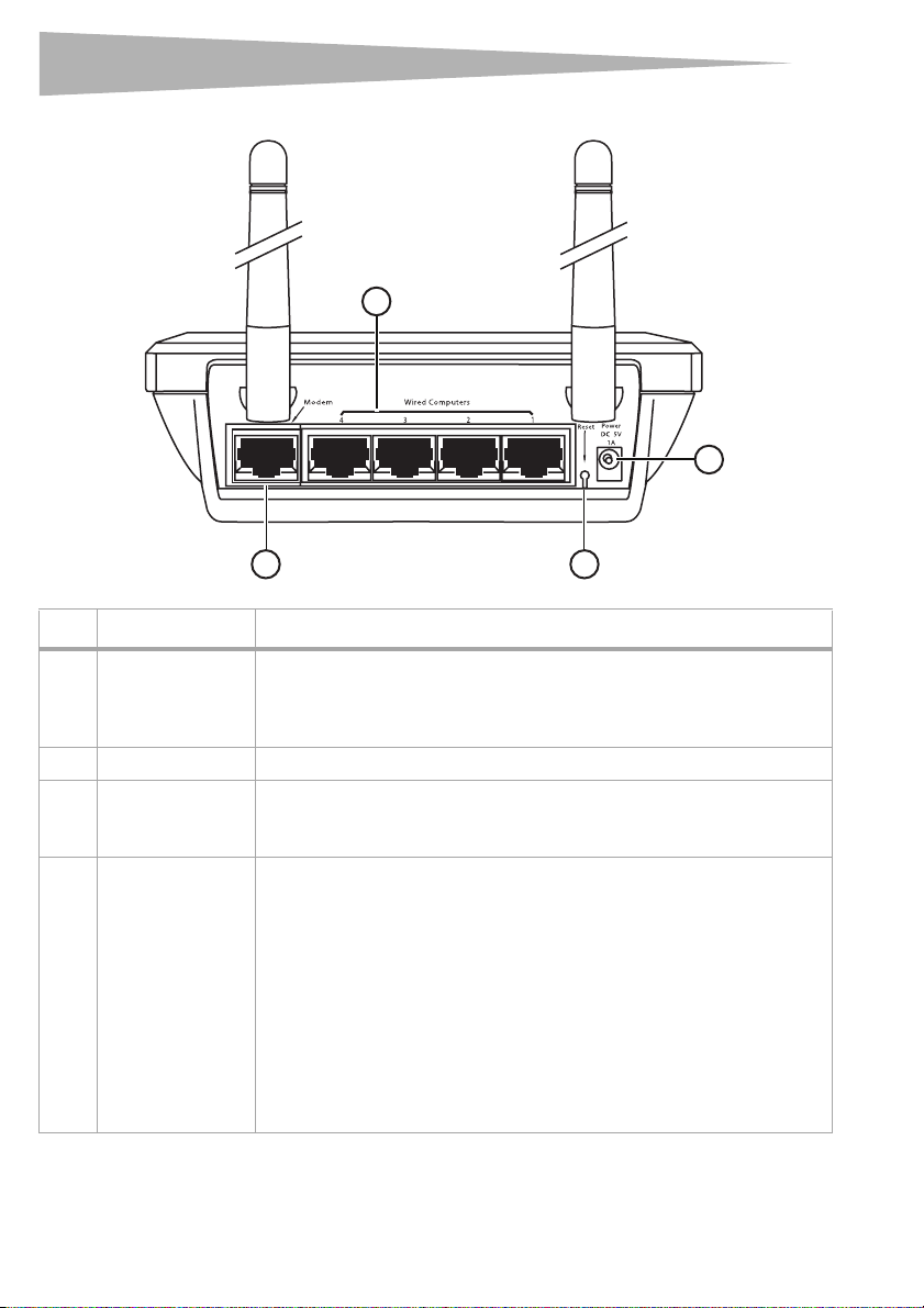
Back panel
Product features
1
2
3
# Component Description
1 Wired computer
ports - Blue
2 Power jack The 5 V DC power supply plugs into this jack.
3 Modem port - Green This port is for connection to your cable or DSL modem. Use the cable that was
4 Reset button The Reset button is used in rare cases when the router may function improperly.
Connect your wired (non-wireless) computers to these ports. These ports are RJ-45,
10/100 auto-negotiation, auto-uplinking ports for standard UTP category 5 or 6
Ethernet cable. The ports are labeled 1 through 4. These ports correspond to the
numbered LEDs on the front of the router.
provided with the modem to connect the modem to this port. Use of a cable other
than the cable supplied with the cable modem may not work properly.
Resetting the router restores the router's normal operation while maintaining the
programmed settings. You can also restore the factory default settings by using the
Reset button. Use the restore option in instances where you may have forgotten your
custom password.
Resetting the router—Push and release the Reset button. The lights on the
router will momentarily flash. The Power/Ready light will begin to blink. When the
Power/Ready light becomes solid again, the reset is complete.
Restoring the Factory Defaults—Press and hold the Reset button for at least 10
seconds, then release it. The lights on the router will momentarily flash. The Power/
Ready light will begin to blink. When the Power/Ready light becomes solid again,
the restore is complete.
4
Page 9

Setting up your wireless route
r
Setting up your wireless router
Modem requirements
Your cable or DSL modem must be equipped with an RJ-45 Ethernet port. Many modems
have both an RJ-45 Ethernet port and a USB connection. If you have a modem with both
Ethernet and USB, and are using the USB connection at this time, you will be instructed to
use the RJ-45 Ethernet port during the installation procedure. If your modem has only a USB
port, you can request a different type of modem from your ISP, or you can, in some cases,
purchase a modem that has an RJ-45 Ethernet port on it.
Important: Always install your router first! if you are installing numerous network devices
for the first time, it is important that your router is connected and running before
attempting to install other network components such as notebook cards and desktop
cards.
Setup assistant
Dynex has provided our Setup Assistant software to make installing your router a simple and
easy task. You can use it to get your router up and running in minutes. The Setup Assistant
requires that your Windows 2000 or XP computer be connected directly to your cable or DSL
modem and that the Internet connection is active and working at the time of installation. If it
is not, you must use the “Alternate Setup Method” section of this User Guide to configure
your router. Additionally, if you are using an operating system other than Windows 2000 or
XP, you must set up the router using the “Alternate Setup Method” section of this User Guide.
Hardware connections
9
To connect the hardware:
1 Unplug your modem's power cord. Put the router next to the modem and raise the
router's antennas.
2 Locate the networking cable that connects your modem and computer. Unplug that
cable from your modem, and plug it into any blue port on the back of the router.
3 Find your new networking cable (included in the box with your router) and connect it
to the green port on the back of the router. Connect the other end to your modem, in
the port that is now free.
4 Plug in your modem's power cord. Wait 60 seconds for the modem to star t up. Plug the
router's power supply into the black port on the back of the router. Plug the other end
into the wall outlet.
5 Wait 20 seconds for the router to start up. Look at the display on the front of the router
and make sure the Modem and one of the Wired Computers icons are lit up in
green. If they are not, recheck your connections.
Running the Setup Assistant software
To run the Setup Assistant software:
1 Shut down any programs that are running on your computer at this time.
2 Turn off any firewall or Internet-connection-sharing software on your computer.
Page 10
10
r
Setting up your wireless route
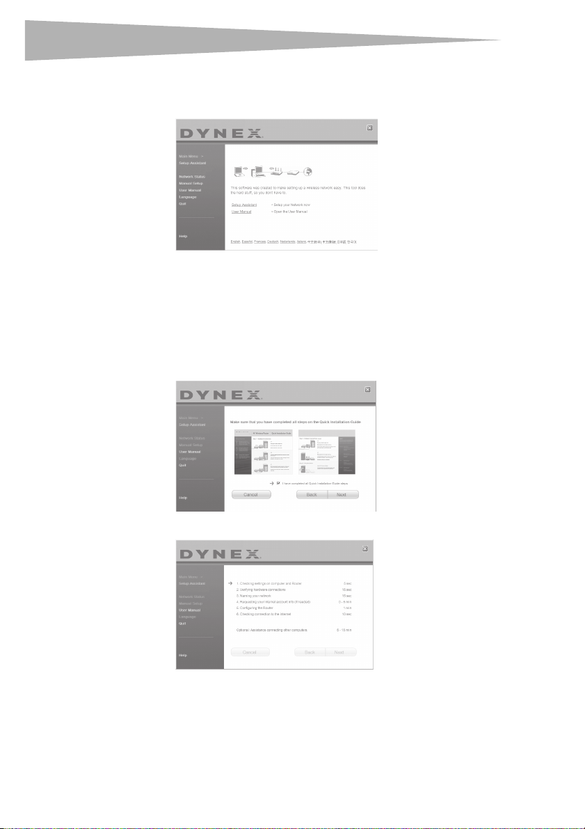
3 Insert the Installation CD into your computer. The Setup Assistant will automatically
appear on your computer's screen within 15 seconds. Double-click the Setup Assistant
to run it, then follow the on-screen instructions.
Important: Run the Setup Assistant from the computer that is directly connected to the
route r.
Note: For Windows users: If the Setup Assistant does not start up automatically, select your
CD/DVD drive from My Computer and double-click the file named Setup Assistant to
start the Setup Assistant.
4 When the Confirmation screen opens, verify that you have completed all QIG steps by
checking the box to the right of the arrow, then click Next to continue.
DYNEX
The Setup Assistant will indicate each time a step in the setup has been completed.
Page 11
Setting up your wireless route
r
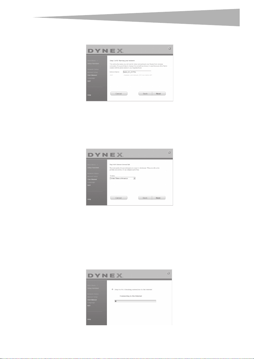
When it is time to name your network, the Setup Assistant will open the Naming your
network screen.
The default wireless network name or Service Set Identifier (SSID). This is the name of
your wireless network to which your computers or devices with wireless network
adapters will connect.
5 You can either accept the default name or change it to something unique. If you
change it, write down the name for future reference. Click Next to continue. The
Internet Account Info screen opens.
11
6 If your Internet account requires a login and password, you will be prompted with a
screen similar to the illustration above. Select your country or ISP from the lists.
The Setup Assistant will now configure your router by sending data to the router and
restarting it. Wait for the on-screen instructions.
Note: Do not disconnect any cable or power off the router while the router is rebooting. Doing
so will render your router inoperable.
After configuring the router, the Setup Assistant checks your connection to the
Internet.
Page 12
12
r
Setting up your wireless route
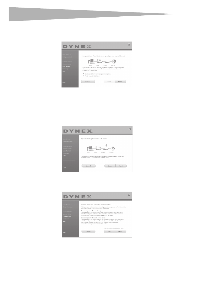
This completes the router installation. You will see the Congratulations screen when
your router can connect to the Internet. You can begin surfing by opening your
browser and going to any Web site.
7 You can use the Setup Assistant to set up your other wired and wireless computers to
connect to the Internet by clicking Next. If you decide to add computers to your router
later, select Exit the Assistant, then click Next.
To troubleshoot the setup:
1 If the Setup Assistant is not able to connect to the Internet, you will see the following
screen. Follow the on-screen instructions to go through the troubleshooting steps.
To use the optional assistance to connect to other computers:
1 This optional step will help you to connect additional wired and wireless computers to
your network. Follow the on-screen instructions.
At this point, your router is set up and working properly. It is now time to connect your other
computers.
Page 13
Setting up your wireless route
r
Connecting computers wirelessly
Computers with wireless network adapters can use this network. If you still need to install
those adapters, do this now. Then follow their instructions on how to connect. When you do
so, look for your network: John's Home Wi-Fi.
Connecting computers with wired cables
Computers with wired network adapters can use this network. If you still need to install
those adapters, do this now. Then simply connect an Ethernet cable between your
computer's network port and one of the available LAN ports (labeled connections to
computers) on the back of this router.]
Once you have verified that your other wired and wireless computers are properly connected,
your network is set up and working. You can now surf the Internet. Click Next to take you
back to the main menu.
Wireless Security Setup
Be sure to complete the basic setup of your router before setting up security. Make sure that
all of your computers (wired and wireless) can successfully connect to the Internet through
your router.
To set up security:
1 On a computer that has a wired (cable) connection to the router, open up a web
browser. In the address field, type 192.168.2.1 (or the IP address you customized),
then click Enter.
13
2 In the menu at left, go to the wireless section and click Security.
If asked to log in, enter your password or, if you have not yet set a custom password,
leave this field blank. Then click, Submit.
Page 14
14
r
Setting up your wireless route
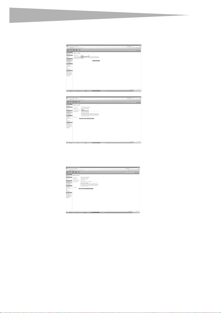
3 You will be asked to pick a security type. We recommend WPA2-PSK as the security
mode and then WPA-PSK+WPA2-PSK as the Authentication, as it is the most secure
and easiest to use. Once you have made your choice, click Apply Changes.
4 In the Pre-shared key field, type a security key that is easy for you to remember. Using
some punctuation will increase your network's security (for example, “My favorite
team is the Tigers!”). Click Apply Changes.
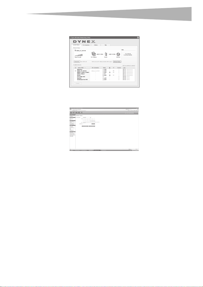
5 Now go to each of your wireless computers. Use the wireless utility software on each to
do the following (see you wireless adapter's user manual for more detailed
instructions):
a. Find your wireless network and connect to it.
b. When prompted, enter the phrase you created above.
Page 15
Setting up your wireless route
r
Note: If a computer does not accept the phrase, it likely does not yet support WPA/WPA2. Go
to your wireless adapter manufacturer's Web site and check for a driver update.
6 If you do not want to update your computer's wireless adapter to work wit h WPA/
WPA2, return to Step 4 and choose WEP. See “WEP Setup” on page 30 for instructions
on setting up WEP.
15
Alternate setup method
The Web-Based Advanced User Interface is a web-based tool that you can use to set up the
router if you do not want to use the Easy Install Wizard. You can also use it to manage
advanced functions of the router. From the Web-Based Advanced User Interface, you can
perform the following tasks:
• View the router's current settings and status
• Configure the router to connect to your ISP with the settings that they provided you
• Change the current network settings such as the Internal IP address, the IP address
pool, DHCP settings, and more
• Set the router's firewall to work with specific applications (port forwarding)
• Set up security features such as client restrictions, MAC address filtering, WEP, and
WPA
• Enable the DMZ feature for a single computer on your network
• Change the router's internal password
• Enable/Disable UPnP (Universal Plug-and-Play)
• Reset the router
• Back up your configuration settings
• Reset the router's default settings
• Update the router's firmware
Page 16

16
r
Setting up your wireless route
To connect your router (step 1):
1 Turn off the power to your modem by unplugging the power supply from the modem.
2 Locate the network cable that is connected between your modem and your computer
and unplug it from your computer, leaving the other end connected to your modem.
3 Plug the loose end of the cable you just unplugged into the port on the back of the
router labeled Modem.
4 Connect a new network cable (not included) from the back of the computer to one of
the wired computer ports labeled 1-4. Note: It does not matter which numbered port
you choose.
5 Turn your cable or DSL modem on by reconnecting the power supply to the modem.
6 Plug the power cord into the wall, then plug the cord into the router's power jack.
7 Make sure that your modem is connected to the router by checking the lights on the
front of the router. The green light labeled Modem should be on if your modem is
connected correctly to the router. If it is not, recheck your connections.
8 Make sure that your computer is connected properly to the router by checking the
lights labeled 1-4. The light that corresponds to the numbered port connected to your
computer should be on if your computer is connected properly. If it is not, recheck your
connections.
To set up your computer's network settings to work with a DHCP server:
• See “Manually configuring network settings” on page 44 for directions.
Configuring the router using the Web-Based Advanced User Interface:
1 Open your Internet browser, the access the router's Web-Based Advanced User
Interface by typing “192.168.2.1” in the address line (you do not need to type in
anything else such as “http://” or “www”), then press Enter. The router's home page
opens.
Note: If you have difficulty accessing the router's Web-Bas ed Advanced User Interface, go to
the section entitled “Manually Configuring Network Settings”.
2 To make any changes to the router's settings, you have to log in. Click Login, or click
on any one of the links on the home page to go to the login screen.
3 In the login screen, leave the password blank (the router ships with no password
entered) and click Submit to log in.
One computer at a time can log into the router for the purposes of making changes to
the settings of the router.
4 After you have logged in to make changes, there are two ways that the computer can
be logged out. Clicking Logout will log the computer out.
- OR -
5 The login will time out after a specified period of time. The default login time-out is 10
minutes. This can be changed from 1 to 99 minutes. For more information, see
“Changing the Login Time-Out Setting” on page 42.
Page 17
Setting up your wireless route
r
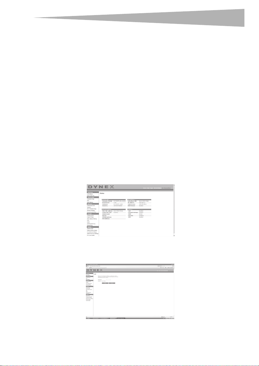
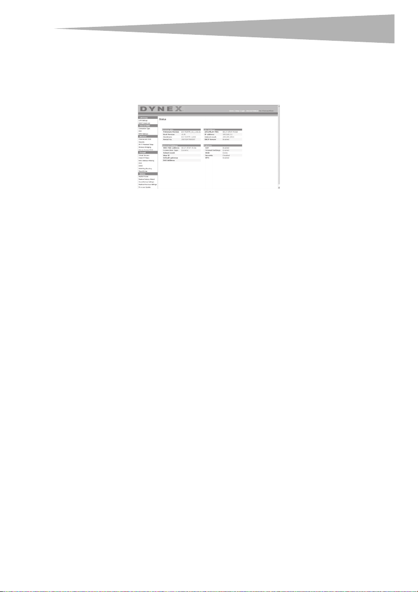
Using the Web-Based Advanced User Interface
The home page is the first page you will see when you access the Web-Based Advanced User
Interface (UI). The home page shows you a quick view of the router's status and settings. All
advanced setup pages can be reached from this page.
Quick-Navigation Links—You can go directly to any of the router's UI pages by clicking
directly on these links. The links are divided into logical categories and grouped by tabs to
make finding a particular setting easier to find. Clicking on the purple header of each tab will
show you a short description of the tab's function.
Home Button—Th e Home button is available in every page of the UI. Pressing this button
will take you back to the home page.
Internet Status Indicator—This indicator is visible in all pages of the UI, indicating the
connection status of the router. When the indicator says connection OK in green, the router
is connected to the Internet. When the router is not connected to the Internet, the indicator
will read no connection in red. The indicator is automatically updated when you make
changes to the settings of the router.
Login/Logout Button—This button enables you to log in and out of the router with the
press of one button. When you are logged into the router, this button will change to read
Logout. Logging into the router will take you to a separate login page where you will need
to enter a password. When you are logged into the router, you can make changes to the
settings. When you are finished making changes, you can log out of the router by clicking the
Logout button.
Help Button—The Help button gives you access to the router's help pages. Help is also
available on many pages by clicking more info next to certain sections of each page.
LAN Settings—Shows you the settings of the Local Area Network (LAN) side of the router.
Changes can be made to the settings by clicking on any one of the links (IP Address, Subnet
Mask, DHCP Server) or by clicking the LAN - Quick Navigation link on the left side of the
screen.
Feature s—Shows the status of the router's NAT, firewall, and wireless features. Changes
can be made to the settings by clicking on any one of the links or by clicking the Quick
Navigation links on the left side of the screen.
Internet Settings—Shows the settings of the Internet/WAN side of the router that
connects to the Internet. Changes to any of these settings can be made by clicking on the
links or by clicking on the Internet/WAN - Quick Navigation link on the left side of the
screen.
17
Page 18
18
r
Version Info—Shows the firmware version, boot-code version, hardware version, and
serial number of the router.
Page Name—The page you are on can be identified by this name. This User Guide will
sometimes refer to pages by name. For instance LAN > LAN Settings refers to the LAN
Settings page.
Configure your router for connection to your Internet Service Provider (ISP)
The Internet/WAN tab is where you will set up your router to connect to your Internet
Service Provider (ISP). The router is capable of connecting to virtually any ISP's system
provided you have correctly configured the router's settings for your ISP's connection type.
Your ISP connection settings are provided to you by your ISP.
To configure the router with the settings that your ISP gave you:
1 Click Connection Type on the left side of the screen, then select the connection type
you use.
2 If your ISP gave you DNS settings, clicking DNS lets you enter DNS address entries for
ISPs that require specific settings.
3 Click MAC address to clone your computer's MAC address or type in a specific WAN
MAC address, if required by your ISP.
4 When you have finished making settings, the Internet Status indicator will read
connection OK if your router is set up properly.
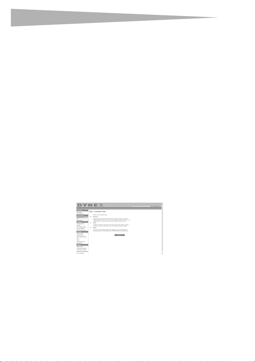
To set your Connection Type:
1 Click Connection Type from the menu on the left side of the screen. The Connection
Type page opens. From this page you can select the type of connection you use by
clicking the button next to your connection type and then clicking Next.
Setting up your wireless route
Setting your Internet Service Provider (ISP) Connection Type to Dynamic IP
A dynamic connection type is the most common connection type used with cable modems.
Setting the connection type to dynamic in many cases is enough to complete the
connection to your ISP. Some dynamic connection types may require a host name. You can
enter your host name in the space provided if you were assigned one. Your host name is
assigned by your ISP. Some dynamic connections may require that you clone the MAC address
of the PC that was originally connected to the modem.
Page 19
Setting up your wireless route
r
Change WAN MAC Address
If your ISP requires a specific MAC address to connect to the service, you can enter a specific
MAC address or clone the current computer's MAC address through this link.
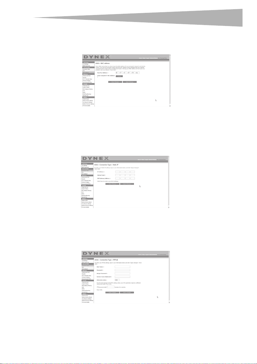
Setting your Internet Service Provider (ISP) Connection Type to Static IP
A static IP address connection type is less common than other connection types. If your ISP
uses static IP addressing, you will need your IP address, subnet mask, and ISP gateway
address. This information is available from your ISP or on the paperwork that your ISP left
with you. Type in your information, then click Apply Changes. After you apply the changes,
the Internet Status indicator will read connection OK if your router is set up correctly.
19
Setting your ISP Connection Type to PPPoE
Most DSL providers use PPPoE as the connection type. If you use a DSL modem to connect to
the Internet, your ISP may use PPPoE to log you into the service. If you have an Internet
connection in your home or small office that doesn't require a modem, you may also use
PPPoE.
Page 20

20
r
Setting up your wireless route
Your connection type is PPPoE if:
• Your ISP gave you a user name and password, which is required to connect to the
Internet;
• Your ISP gave you software such as WinPOET or Enternet300 that you use to connect to
the Internet; or
• You have to double-click on a desktop icon other than your browser to get on the
Internet.
Enter the following:
User Name–This space is provided to type in your user name that was assigned by your ISP.
Password–Type in your password and re-type it into the Retype Password box to confirm it.
Service Name–A service name is rarely required by an ISP. If you are not sure if your ISP
requires a service name, leave this blank.
MTU–The MTU setting should never be changed unless your ISP gives you a specific MTU
setting. Making changes to the MTU setting can cause problems with your Internet
connection including disconnection from the Internet, slow Internet access, and problems
with Internet applications working properly.
Disconnect after X minutes…–This feature is used to automatically disconnect the router
from your ISP when there is no activity for a specified period of time. For instance, placing a
check mark next to this option and entering 5 into the minute field will cause the router to
disconnect from the Internet after five minutes of no Internet activity. This option should be
used if you pay for your Internet service by the minute.
Setting Custom Domain Name Server (DNS) Settings
A Domain Name Server is a server located on the Internet that translates Universal Resource
Locators (URLs) like “www.dynex.com” into IP addresses. Many Internet Service Providers
(ISPs) do not require you to enter this information into the router. The Automatic from ISP
box should be checked if your ISP did not give you a specific DNS address. If you are using a
static IP connection type, then you may need to enter a specific DNS address and secondary
DNS address for your connection to work properly. If your connection type is dynamic or
PPPoE, it is likely that you do not have to enter a DNS address. Leave the Automatic from
ISP box checked. To enter the DNS address settings, uncheck the Automatic from ISP box
and enter your DNS entries in the spaces provided. Click Apply Changes to save the settings.
Page 21
Setting up your wireless route
r
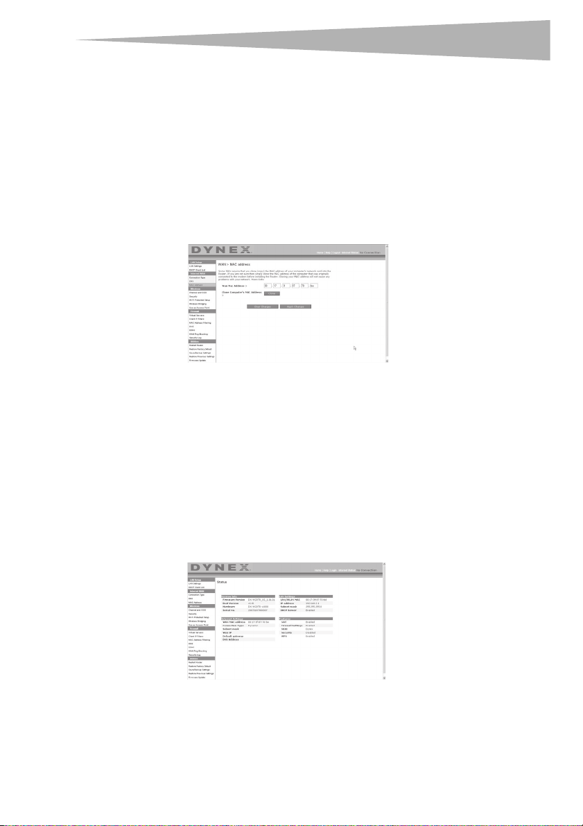
Configuring your WAN Media Access Controller (MAC) Address
All network components including cards, adapters, and routers, have a unique “serial
number” called a MAC address. Your Internet Service Provider may record the MAC address of
your computer's adapter and only let that particular computer connect to the Internet
service. When you install the router, its own MAC address will be “seen” by the ISP and may
cause the connection not to work. Dynex has provided the ability to clone (copy) the MAC
address of the computer into the router. This MAC address, in turn, will be seen by the ISP's
system as the original MAC address and will allow the connection to work. If you are not sure
whether your ISP needs to see the original MAC address, simply clone the MAC address of the
computer that was originally connected to the modem. Cloning the address will not cause
any problems with your network.
To clone your MAC Address:
1 Make sure that you are using the computer that was ORIGINALLY CONNECTED to your
modem before the router was installed. Click
2 Click Clone, then click Apply Changes. Your MAC address is now cloned to the router.
To enter a specific MAC Address:
• Type in a MAC address in the spaces provided, then click Apply Changes to save the
changes. The router's WAN MAC address is changed to the MAC address you specified.
Using the Web-Based Advanced User Interface
Using your Internet browser, you can access the router's Web-Based Advanced User Interface.
Open your browser and enter 192.168.2.1 (do not type in anything else such as “http://
” or “www”), then press Enter. The router's home page opens in your browser window.
21
Page 22
22
r
Setting up your wireless route
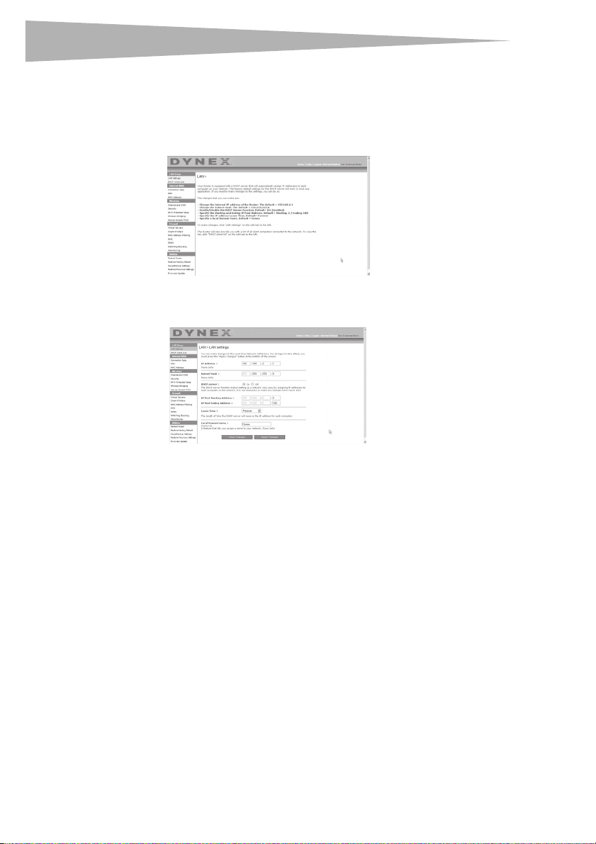
Viewing the LAN Settings
Clicking on the header of the LAN Setup tab will take you its header page. A quick
description of the functions can be found here. To view the settings or make changes to any
of the LAN settings, click LAN Settings, or to view the list of connected computers, click
DHCP Client List.
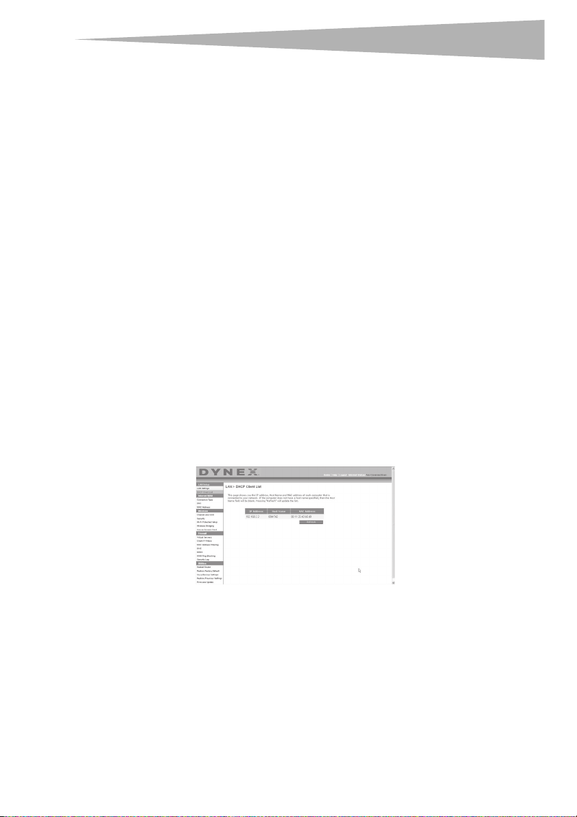
Changing LAN Settings
All settings for the internal LAN setup of the router can be viewed and changed here.
IP Address–T he IP address is the internal IP address of the router. The default IP address is
192.168.2.1. To access the Web-Based Advanced User Interface, type this IP address into the
address bar of your browser. This address can be changed if needed. To change the IP address,
type in the new IP address and click Apply Changes. The IP address you choose should be a
non-routable IP.
Examples of a non-routable IP are: 192.168.x.x (where x is anywhere between 0 and 255),
and 10.x.x.x (where x is anything between 0 and 255).
Subnet Mask–There is no need to change the subnet mask. This is a unique, advanced
feature of your Dynex router. It is possible to change the subnet mask if necessary; however,
do NOT make changes to the subnet mask unless you have a specific reason to do so. The
default setting is 255.255.255.0.
DHCP Server–The DHCP server function makes setting up a network very easy by assigning
IP addresses to each computer on the network automatically. The default setting is On. The
DHCP server can be turned OFF if necessary; however, in order to do so you must manually set
a static IP address for each computer on your network. To turn off the DHCP server, select Off,
then click Apply Changes.
Page 23
Setting up your wireless route
r
IP Pool–The range of IP addresses set aside for dynamic assignment to the computers on
your network. The default is 2-100 (99 computers). If you want to change this number, you
can do so by entering a new starting and ending IP address and clicking Apply Changes.
The DHCP server can assign 100 IP addresses automatically. This means that you cannot
specify an IP address pool larger than 100 computers. For example, starting at 50 means you
have to end at 150 or lower so as not to exceed the 100-client limit. The starting IP address
must be lower in number than the ending IP address.
Lease Time–The length of time the DHCP server will reserve the IP address for each
computer. We recommend that you leave the lease time set to Forever. The default setting is
Fore ver, meaning that any time a computer is assigned an IP address by the DHCP server,
the IP address will not change for that particular computer. Setting lease times for shorter
intervals such as one day or one hour frees IP addresses after the specified period of time.
This also means that a particular computer's IP address may change over time. If you have set
any of the other advanced features of the router such as DMZ or client IP filters, these are
dependent on the IP address. For this reason, you will not want the IP address to change.
Local Domain Name–The default setting is Dynex. You can set a local domain name
(network name) for your network. There is no need to change this setting unless you have a
specific advanced need to do so. You can name the network anything you want such as “MY
NETWORK”.
Viewing the DHCP Client List Page
You can view a list of the computers (known as clients), which are connected to your
network. You are able to view the IP address of the computer, the host name (if the computer
has been assigned one), and the MAC address of the computer's network interface card (NIC).
Pressing the Refresh button will update the list. If there have been any changes, the list will
be updated.
23
Page 24
24
r
Setting up your wireless route
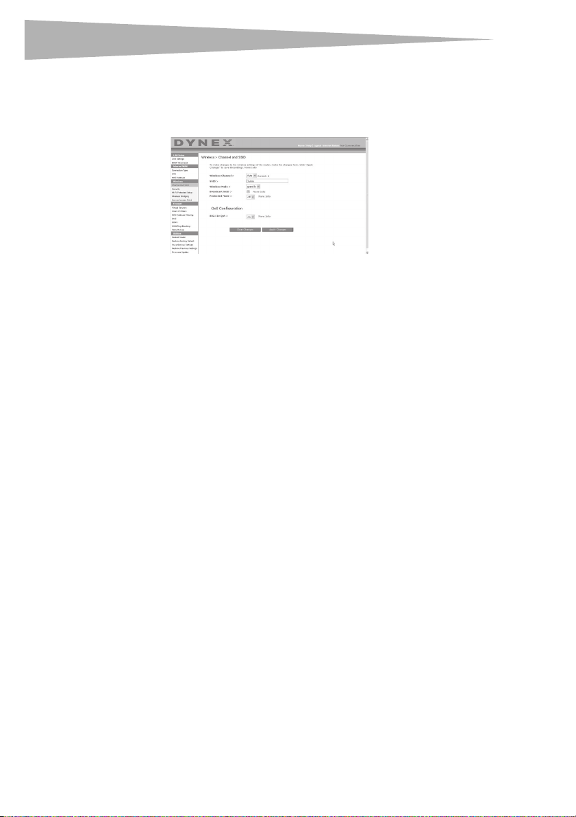
Configuring the Wireless Network Settings
Clicking on the header of the Wireless tab will take you to the Wirel ess page. Under the
Wireless tab, there are links that allow you to make changes to the wireless network
settings.
Changing the Wireless Network Name (SSID)
To identify your wireless network, an SSID (Service Set Identifier) is used. The default SSID of
the router is “Dynex”. You can change this to anything you want to or you can leave it
unchanged. If there are other wireless networks operating in your area, you will want to
make sure that your SSID is unique (does not match that of another wireless network in the
area). To change the SSID, type in the SSID that you want to use in the SSID field and click
Apply Changes. The change is immediate. If you make a change to the SSID, your
wireless-equipped computers may also need to be reconfigured to connect to your new
network name. Refer to the documentation of your wireless network adapter for information
on making this change.
Using the Wireless Mode Switch
Your router can operate in three different wireless modes: “g and b”, “g only”, and “b only”.
The different modes are explained below.
g and b Mode–In this mode, the router is compatible with 802.11b and 802.11g wireless
clients simultaneously. This is the factory default mode and ensures successful operation
with all Wi-Fi-compatible devices. If you have a mix of 802.11b and 802.11g clients in your
network, we recommend setting the router to g and b mode. This setting should only be
changed if you have a specific reason to do so.
g only Mode–g only mode works with 802.11g clients only. This mode is recommended
only if you want to prevent 802.11b clients from accessing your network. To switch modes,
select the desired mode from the Wireless Mode list, then click Apply Changes.
b only Mode–We recommend you DO NOT use this mode unless you have a very specific
reason to do so. This mode exists only to solve unique problems that may occur with some
802.11b client adapters and is NOT necessary for interoperability of 802.11g and 802.11b
standards.
Page 25

Setting up your wireless route
r
When to use b only Mode
In some cases, older 802.11b clients may not be compatible with 802.11g wireless. These
adapters tend to be of inferior design and may use older drivers or technology. Switching to
this mode can solve problems that sometimes occur with these clients. If you suspect that
you are using a client adapter that falls into this category of adapters, first check with the
adapter vendor to see if there is a driver update. If there is no driver update available,
switching to b only mode may fix your problem. Please note that switching to b only mode
will decrease 802.11g performance.
Enhanced G Mode*–The router supports two high-speed modes, 125 Enhanced G mode
and frame-bursting mode.
Selecting 125 Enhanced G mode will result in all devices running in 125 Enhanced G mode if
all devices are capable of 125 Mbps speeds. If any non-125 Enhanced G devices connect or
associates with the network, the router will automatically shift the entire network back to
frame-bursting mode.
Selecting Frame Bursting results in all devices capable of frame-bursting to function in
frame-bursting mode, and all clients not capable, to operate in normal 802.11g modes.
frame-bursting mode supports both frame-bursting-enabled devices and
non-frame-bursting-enabled devices simultaneously. Frame-bursting mode is based on the
unreleased 802.11e specification.
Selecting Off will disable Turbo mode.
*When operating in 125 Enhanced G Mode, this Wi-Fi device achieves an actual throughput
of up to 34.1 Mbps, which is the equivalent throughput of a system following 802.11g
protocol and operating at a signaling rate of 125 Mbps. Actual throughput will vary
depending on environmental, operational, and other factors.
QoS (Quality of Service) Configuration–QoS prioritizes important data on your network
such as multimedia content and Voice over IP (VoIP) so it will not be interfered with by other
data being sent over the network. Based on 802.11e, you can turn this feature on or off by
selecting it from the drop-down menu (3) and choosing the acknowledgement mode you
want to use. If you plan to stream multimedia content or use VoIP on your network, we
recommend that you enable the QoS feature.
Changing the Wireless Channel
There are a number of operating channels you can choose from. In the United States, there
are 11 channels. In Australia, the United Kingdom, and most of Europe, there are 13
channels. In a small number of other countries, there are other channel requirements. Your
router is configured to operate on the proper channels for the country you reside in. The
default channel is 11 (unless you are in a country that does not allow channel 11). The
channel can be changed if needed. If there are other wireless networks operating in your
area, your network should be set to operate on a channel that is different than the other
wireless networks. For best performance, use a channel that is at least five channels away
from the other wireless network. For instance, if another network is operating on channel 11,
then set your network to channel 6 or below. To change the channel, select the channel from
the list, then click Apply Changes. The change is immediate.
25
Page 26

26
r
Using the Broadcast SSID Feature
Note: This advanced feature should be employed by advanced users only.
For security, you can choose not to broadcast your network's SSID. Doing so will keep your
network name hidden from computers that are scanning for the presence of wireless
networks. To turn off the broadcast of the SSID, remove the check mark from the box next to
Broadcast SSID, then click Apply Changes. The change is immediate. Each computer now
needs to be set to connect to your specific SSID; an SSID of ANY will no longer be accepted.
Refer to the documentation of your wireless network adapter for information on making this
change.
Protected Mode Switch–As part of the 802.11g specification, Protected mode ensures
proper operation of 802.11g clients and access points when there is heavy 802.11b traffic in
the operating environment. When Protected mode is ON, 802.11g scans for other wireless
network traffic before it transmits data. Therefore, using this mode in environments with
HEAVY 802.11b traffic or interference achieves best performance results. If you are in an
environment with very little-or no-other wireless network traffic, your best performance will
be achieved with Protected mode OFF.
Securing your Wi-Fi® Network
Here are a few different ways you can maximize the security of your wireless network and
protect your data from prying eyes and ears. This section is intended for the home, home
office, and small office user.
At the time of this User Manual's publication, there are four encryption methods available.
Setting up your wireless route
Name
Acronym
Security
Features
64-Bit Wired
Equivalent
Privacy
64-bit WEP 128-bit WEP WPA-TKIP/AES (or just
Good Better Best Best
Static keys Static keys Dynamic key
Encryption keys based
on RC4 algorithm
(typically 40-bit keys)
128-Bit Wired
Equivalent
Privacy
More secure than
64-bit WEP using a
key length of 104 bits
plus 24 additional bits
of system generated
data
Wi-Fi Protected
Access-TKIP
WPA)
encryption and
mutual
authentication
TKIP (Temporal Key
Integrity Protocol)
added so that keys are
rotated and
encryption is
strengthened
Wi-Fi Protected
WPA2-AES (or just
WPA2)
Dynamic key
encryption and
mutual
authentication
AES (Advanced
Encryption Standard)
does not cause any
throughput loss
Access 2
Page 27

Setting up your wireless route
r
Wired Equivalent Privacy (WEP)
WEP is a common protocol that adds security to all Wi-Fi-compliant wireless products. WEP
gives wireless networks the equivalent level of privacy protection as a comparable wired
network.
64-Bit WEP—64-bit WEP was first introduced with 64-bit encryption, which includes a key
length of 40 bits plus 24 additional bits of system-generated data (64 bits total). Some
hardware manufacturers refer to 64-bit as 40-bit encryption. Shortly after the technology
was introduced, researchers found that 64-bit encryption was too easy to decode.
128-Bit Encryption—As a result of 64-bit WEP’s potential security weaknesses, a more
secure method of 128-bit encryption was developed. 128-bit encryption includes a key
length of 104 bits plus 24 additional bits of system-generated data (128 bits total). Some
hardware manufacturers refer to 128-bit as 104-bit encryption. Most of the new wireless
equipment in the market today supports both 64-bit and 128-bit WEP encryption, but you
might have older equipment that only supports 64-bit WEP. All wireless products from Dynex
will support both 64-bit and 128-bit WEP.
Encryption Keys—After selecting either the 64-bit or 128-bit WEP encryption mode, it is
critical that you generate an encryption key. If the encryption key is not consistent
throughout the entire wireless network, your wireless networking devices will be unable to
communicate with one another. You can enter your key by typing in the hex key manually, or
you can type a passphrase into the Passphrase field, then click Generate to create a key. A
hex (hexadecimal) key is a combination of numbers and letters from A–F and 0–9. For 64-bit
WEP, you need to enter 10 hex keys. For 128-bit WEP, you need to enter 26 hex keys.
For instance:
AF 0F 4B C3 D4 = 64-bit WEP key
C3 03 0F AF 0F 4B B2 C3 D4 4B C3 D4 E7 = 128-bit WEP key
The WEP passphrase is NOT the same as a WEP key. Your card uses this passphrase to
generate your WEP keys, but different hardware manufacturers might have different
methods on generating the keys. If you have multiple vendors’ equipment in your network,
the easiest thing to do is to use the hex WEP key from your wireless router and enter it
manually into the hex WEP key table in your card’s configuration screen.
Security Sync (WPS)
Your router is equipped with the latest security standard, called Wi-Fi Protected Access
(WPA2), and the legacy security standard, called Wired Equivalent Privacy (WEP). Your router
also supports the Wi-Fi Protected Setup (WPS) specification, which simplifies the setup of a
wireless network. WPS uses familiar methodologies, such as typing in a Personal
Identification Number (PIN) or pushing a button, to enable users to automatically configure
network names and strong WPA/WPA2 data encryption and authentication. By default,
wireless security is disabled. To enable security, you need to determine which standard you
want to use. To access the security settings, click Security on the Wireless tab.
27
Page 28
28
r
Setting up your wireless route
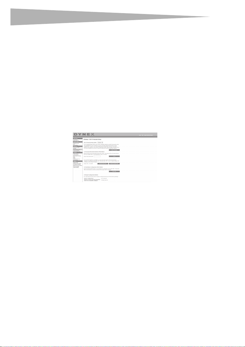
Using Security Sync (Wi-Fi Protected Setup)
Security Sync (WPS) uses WPA2 for encryption. It does not provide additional security, but
rather, standardizes the method for securing your wireless network. You may use either the
Push Button Configuration (PBC) method or PIN method to let a device access to your
wireless network. Conceptually, the two methods work as follows:
PBC: Push and hold the Security Sync (WPS) button located on the top of your router for
three seconds. Then initiate the Security Sync (WPS) procedure on the client device within
two minutes. Your client will automatically exchange the security information and be added
to your wireless network. The client has now been securely added to your wireless network.
Pushing the Security Sync button will automatically enable WPS. The PBC method can also
be initiated from the notebook computer.
PIN: The client device has a PIN number (either four or eight digits) that is associated with
WPS. Enable WPS through the GUI shown below. Enter the client's PIN into the Router's
internal registrar (accessed through this GUI). The client will be automatically enrolled into
your wireless network within two minutes.
1. Wi-Fi Protected Setup (WPS): Enabled or Disabled.
2. Personal Identification Number (PIN) Method: In this method, a wireless client wishing to
access your network must supply a 4- or 8-digit PIN to the router. After clicking "Enroll",
you must start the WPS handshaking procedure from the client within two minutes.
3. Router PIN: If an external registrar is available, you can enter in the router's PIN to the
registrar. Click Generate New PIN to change the PIN from the default value, or click
Restore Default PIN to reset the PIN value.
4. Push Button Configuration (PBC) Method: PBC is an alternate method to connect to a
WPS network. Push the Security Sync button located on the back of the router for three
seconds, and then initiate the PBC on the client device. Alternatively, push the "Start
PBC" soft button to start this process.
5. Manual Configuration Method: This section lists the default security settings if not using
WPS.
Therouter features WPA2, which is the second generation of the WPA-based 802.11i
standard. It offers a higher level of wireless security by combining advanced network
authentication and stronger Advanced Encryption Standard (AES) encryption methods.
Page 29
Setting up your wireless route
r
Wi-Fi Protected Areas (WPA)
WPA is a new Wi-Fi standard that improves upon the security features of WEP. To use WPA
security, the drivers and software of your wireless equipment must be upgraded to support
it. These updates will be found on your wireless vendor’s Web site. There are three types of
WPA security: WPA-PSK (no server), WPA (with radius server), and WPA2.
WPA-PSK (no server) uses what is known as a pre-shared key as the network key. A
network key is a password that is between eight and 63 characters long. It can be a
combination of letters, numbers, or characters. Each client uses the same network key to
access the network. Typically, this is the mode that will be used in a home environment.
WPA (with radius server) is a system where a radius server distributes the network key to
the clients automatically. This is typically found in a business environment.
WPA2 requires Advanced Encryption Standard (AES) for encryption of data, which offers
much greater security than WPA. WPA uses both Temporal Key Integrity Protocol (TKIP) and
AES for encryption.
Most Wi-Fi products ship with security turned off. So once you have your network working,
you need to activate WEP or WPA and make sure all your wireless devices are sharing the
same network key.
IMPORTANT: You must now set all wireless network cards/adapters to match these settings.
Sharing the Same Network Keys
Most Wi-Fi products ship with security turned off. So once you have your network working,
you need to activate WEP or WPA and make sure your wireless networking devices are
sharing the same network key.
29
The Wireless G Desktop Card cannot access the network because it is using a different
network key than the network key that is configured on the wireless enhanced G router.
Using a Hexadecimal Key
A hexadecimal key is a combination of numbers and letters from A-F and 0-9. 64-bit keys are
five two-digit numbers. 128-bit keys are 13 two-digit numbers.
For instance:
AF 0F 4B C3 D4 = 64-bit key
C3 03 0F AF 0F 4B B2 C3 D4 4B C3 D4 E7 = 128-bit key
Note to Mac u sers: Original Apple® AirPort® products support 64-bit encryption only. Apple
AirPort 2 products can support 64-bit or 128-bit encryption. Please check your product to
see which version you are using. If you cannot configure your network with 128-bit
encryption, try 64-bit encryption.
Page 30

30
r
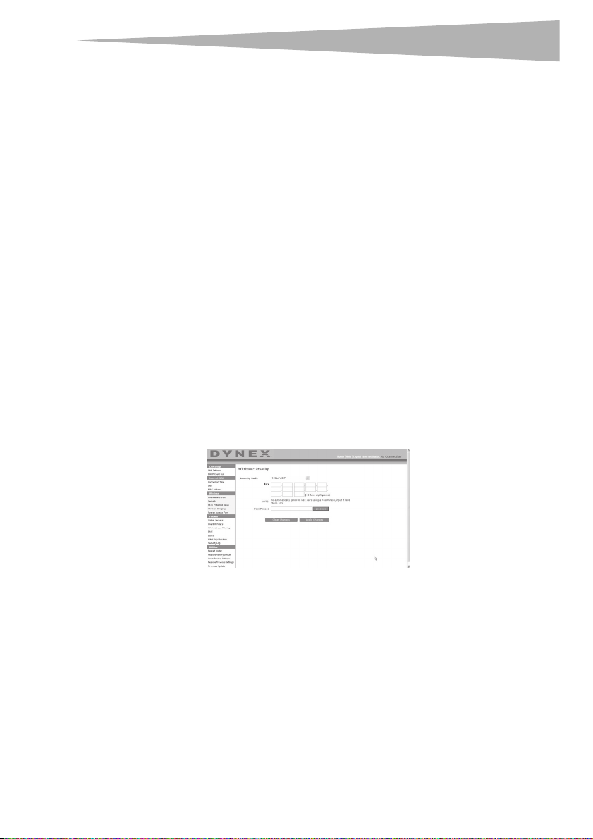
WEP Setup
Setting up your wireless route
To set up 64-Bit WEP encryption:
1 Click Security under the Wireless heading on the left menu. The Wireless > Security
page opens.
2 Select 64-bit WEP from the Security Mode list.
3 Enter your key by typing in the hex key manually, or you can put a check mark in
Passphrase, then type in your passphrase.
4 Click Generate to generate four different hex keys.
A hex (hexadecimal) key is a combination of numbers and letters from A-F and 0-9. For
64-bit WEP, you need to enter 10 hex characters.
For example: AF 0F 4B C3 D4 = 64-bit WEP key
5 Click Apply Changes to save the setting.
Caution : If you are configuring the wireless enhanced G router or access point from a
computer with a wireless client, you will need to make sure that security is turned ON for
this wireless client. If this is not done, your client will lose its wireless connection.
To set up 128-Bit WEP encryption:
Note to Mac users: The passphrase option will not operate with Apple AirPort. To configure
encryption for your Mac computer, set the encryption using the manual method described
in the next section.
1 Click Security under the Wireless heading on the left menu. The Wireless Security
page opens.
2 Select 128-bit WEP from the Security Mode list.
3 Enter your key by typing in the hex key manually, or you can put a check mark in
Passphrase, then type in your passphrase.
4 Click Generate to generate four different hex keys.
A hex (hexadecimal) key is a combination of numbers and letters from A-F and 0-9. For
128-bit WEP, you need to enter 26 hex characters.
For example: C3 03 0F AF 0F 4B B2 C3 D4 4B C3 D4 E7 = 128-bit WEP key
5 Click Apply Changes to save the setting.
Caution : If you are configuring the wireless enhanced G router or access point from a
computer with a wireless client, you will need to make sure that security is turned ON for
this wireless client. If this is not done, your client will lose its wireless connection.
Changing the Wireless Security Settings
Your router is equipped with WPA (Wi-Fi Protected Access), the latest wireless security
standard. It also supports the legacy security standard, WEP (Wired Equivalent Privacy). By
default, wireless security is disabled. To enable security, you must first determine which
standard you want to use. To access the security settings, click Security under the Wireless
heading on the left menu.
Page 31

Setting up your wireless route
r
WPA Setup
Note: To use WPA security, all your clients must be upgraded to drivers and software that
support it. At the time of this User Manual's publication, a security patch download is
available, for free, from Microsoft®. This patch works only with the Windows XP operating
system. You also need to download the latest driver for your Dynex Wireless Enhanced G
Desktop or Notebook Network Card from the Dynex support site. Other operating systems
are not supported at this time. Microsoft's patch only supports devices with WPA-enabled
drivers such as Dynex 802.11g products.
WPA uses a so-called pre-shared key as the security key. A pre-shared key is a password that
is between eight and 63 characters long. It can be a combination of letters, numbers, and
other characters. Each client uses the same key to access the network. Typically, this mode
will be used in a home environment.
WPA2 is the second generation of WPA, offering a more advanced encryption technique over
WPA.
To set up WPA/WPA2:
1 Click Security under the Wireless heading on the left menu. The Wireless > Security
page opens.
2 Select WPA/WPA2-Personal (PSK) from the Security Mode list.
3 Select WPA-PSK for just WPA authentication, or WPA2-PSK for just WPA2
authentication, or you may select WPA-PSK + WPA2-PSK for WPA and WPA2 as the
authentication type.
4 Enter your pre-shared key. This can be from eight to 63 characters and can be letters,
numbers, or symbols. This same key must be used on all of the clients that you set up.
This pre-shared key will allow users full access to your network including shared files
and printers.
5 Click Apply Changes to finish. You must now set all clients to match these settings
depending on the type of access you want them to have.
Note: If your wireless card is not equipped with WPA-enabled software, a file from Microsoft
called Windows XP Su pport Patch for W ireless Protected Acce ss is available for free
download.
The file that Microsoft has made available works only with Windows XP. Other operating
systems are not supported at this time.
Important: You also need to ensure that the wireless card manufacturer supports WPA and
that you have downloaded and installed the latest driver from their support site.
To set up Windows XP Wireless Network Utility to use WPA-PSK:
1 Under Windows XP, click Start, Control Panel, Network Connections.
2 Right-click Wireless Network Connection Properties, then click Properties.
31
Page 32

32
r
Setting up your wireless route
3 Click the Wireless Networks tab. The following screen opens.
4 Make sure that the Use Windows to configure my wireless network settings box
is checked.
5 Click the Wireless Networks tab, then click Configure. The following screen opens.
6 For a home or small business user, select WPA-PSK under Network Authentication.
Note: Select WPA if you are using this computer to connect to a corporate network that
supports an authentication server such as a radius server. Consult your network
administrator for further information.
7 Select TKIP or AES under Data Encryption. This setting must be identical to the
router that you set up.
8 Type in your encryption key in the Network key box.
Page 33

Setting up your wireless route
r
Important: Enter your pre-shared key. This can be from eight to 63 characters and can be
letters, numbers, or symbols. This same key must be used on all of the clients that you set
up.
9 Click OK to apply settings.
Using the Access Point Mode
Note: This advanced feature should be employed by advanced users only. The router can be
configured to work as a wireless network access point. Using this mode will defeat the NAT
IP sharing feature and DHCP server. In Access Point (AP) mode, the router will need to be
configured with an IP address that is in the same subnet as the rest of the network that
you will bridge to. The default IP address is 192.168.2.254 and subnet mask is
255.255.255.0. These can be customized for your needs.
To use the Access Point mode:
1 Click Use as access point under the Wireless heading on the left menu. The Wirel ess
> Use as Access Point page opens.
2 Select Enable. When you select this option, you will be able to change the IP settings.
3 Set your IP settings to match your network, then click Apply Changes.
4 Connect a cable from the Modem port on the router to your existing network.
The router is now acting as an access point. To access the router's Web-Based
Advanced User Interface again, type the IP address you specified into your browser's
navigation bar. You can set the encryption settings, MAC address filtering, SSID, and
channel normally.
Configuring the Firewall
Your router is equipped with a firewall that will protect your network from a wide array of
common hacker attacks including:
• IP Spoofing
• SYN flood
•Land Attack
• UDP flooding
• Ping of Death (PoD)
• Tear Drop Attack
• Denial of Service (DoS)
•ICMP defect
•IP with zero length
•RIP defect
33
Page 34

34
r
•Smurf Attack
• Fragment flooding
•TCP Null Scan
The firewall also masks common ports that are frequently used to attack networks. These
ports appear to be Stealth, meaning that for all intents and purposes, they do not exist to a
would-be hacker. You can turn the firewall function off if needed, however, it is
recommended that you leave the firewall enabled. Disabling the firewall protection will not
leave your network completely vulnerable to hacker attacks, but it is recommended that you
leave the firewall enabled.
Configuring Internal Forwarding Settings
The Virtual Servers function lets you route external (Internet) calls for services such as a Web
server (port 80), FTP server (Port 21), or other applications through your router to your
internal network. Since your internal computers are protected by a firewall, computers
outside your network (over the Internet) cannot get to them because they cannot be seen.
You will need to contact the application vendor to find out which port settings you need.
Setting up your wireless route
To enter settings into the virtual server:
1 Open the Virtual Servers page, then enter the IP address in the space provided for the
internal (server) machine, and the port(s) required to pass.
2 Select the port type (TCP or UDP), check the Enable box, then click Apply Changes.
Each inbound port entry has two fields with five characters maximum per field that
allows a start and end port range, for example, [xxxxx]-[xxxxx]. For each entry, you
can enter a single port value by filling in the two fields with the same value (e.g.
[7500]-[7500]) or a wide range of ports (for example [7500]-[9000]). If you need
multiple single port values or a combination of ranges and a single value, you must
use multiple entries up to the maximum of 20 entries (for example, 1. [7500]-[7500],
2. [8023]-[8023], 3. [9000]-[9000]). You can only pass one port per internal IP
Page 35

Setting up your wireless route
r
address. Opening ports in your firewall can pose a security risk. You can enable and
disable settings very quickly. It is recommended that you disable the settings when
you are not using a specific application.
Setting Client IP Filters
The router can be configured to restrict access to the Internet, e-mail, or other network
services at specific days and times. Restriction can be set for a single computer, a range of
computers, or multiple computers.
To restrict Internet access to a single computer:
1 Open the Firewall > Client IP filters page, then enter the IP address of the computer you
wish to restrict access to in the IP fields.
2 Enter 80 in both the port fields, select Both, then select Block. You can also select
Always to block access all of the time.
3 Select the day to start on top, the time to start on top, the day to end on the bottom,
and the time to stop on the bottom.
4 Select Enable, then click Apply Changes. The computer at the IP address you
specified will now be blocked from Internet access at the times you specified. Be sure
you have selected the correct time zone under Utilities> System Settings> Time
Zone.
Setting MAC Address Filtering
The MAC address filter is a powerful security feature that allows you to specify which
computers are allowed on the network. Any computer attempting to access the network that
is not specified in the filter list will be denied access. When you enable this feature, you must
enter the MAC address of each client (computer) on your network to allow network access to
each.
35
Page 36

36
r
To set MAC Address Filtering:
1 Open the Firewall > MAC Address filters page, then click Enable MAC Address
Filtering.
2 Enter the MAC address of each computer on your network by clicking in the space
provided and entering the MAC address of the computer you want to add to the list.
3 Click Add, then click Apply Changes to save the settings. You can have a
MAC-address-filtering list of up to 32 computers.
Note: You will not be able to delete the MAC address of the computer you are using to access
the router's administrative functions (the computer you are using now).
Enabling the Demilitarized Zone (DMZ)
The DMZ feature lets you specify one computer on your network to be placed outside of the
firewall. This may be necessary if the firewall is causing problems with an application such as
a game or video conferencing application. Use this feature on a temporary basis. The
computer in the DMZ is NOT protected from hacker attacks. If your ISP subscription provides
you with additional public (WAN) IP addresses, additional computers can be placed outside
the firewall provided each computer uses a different public (WAN) IP.
Setting up your wireless route
To set up a DMZ for a computer:
•Open the Firewall > DMZ page and enter the last digits of the computer’s IP address in
the IP field, click Enable, then click Apply Changes for the change to take effect.
WAN Ping Blocking
Computer hackers use what is known as pinging to find potential victims on the Internet. By
pinging a specific IP address and receiving a response from the IP address, a hacker can
determine that something of interest might be there. The router can be set up so it will not
respond to an ICMP ping from the outside. This heightens the level of security of your router.
To turn off the ping response
•Open the Firewall > WAN Ping Blocking page and select Block ICMP Ping, then click
Apply Changes. The router will not respond to an ICMP ping.
Page 37

Setting up your wireless route
r
Utilities tab
This screen lets you manage different parameters of the router and perform certain
administrative functions.
Restarting the router
Sometimes it may be necessary to restart or reboot the router if it begins working
improperly. Restarting or rebooting the router will NOT delete any of your configuration
settings.
To restart the router to restore normal operation:
1 Under the Utilities heading on the left menu, click Restart Router. The Restart
Router page opens.
37
2 Click the Restart Router button. The following message appears.
3 Click OK. The following message appears.
4 Click OK. Restarting the router can take up to 25 seconds. It is important not to turn off
the power to the router during the restart.
A 25-second countdown will appear on the screen. When the countdown reaches zero,
the router will be restarted. The router's home page should appear automatically. If
not, type in the router's address (default = 192.168.2.1) into the navigation bar of
your browser.
Page 38

38
r
Restoring factory default settings
Using this option will restore all of the settings in the router to the factory (default) settings.
It is recommended that you back up your settings before you restore all of the defaults.
To restore factory default settings:
1 Under the Utilities heading on the left menu, click Restore Defaults. The following
warning will appear.
2 Click OK. The following message appears.
3 Click OK. Restoring the defaults includes restarting the router. Restarting the router
can take up to 25 seconds. It is important not to turn off the power to the router during
the restart.
A 25-second countdown will appear on the screen. When the countdown reaches zero,
the router will be restarted. The router's home page should appear automatically. If
not, type in the router's address (default = 192.168.2.1) into the navigation bar of
your browser.
Saving a current configuration
You can save your current configuration by using this feature. Saving your configuration will
allow you to restore it later if your settings are lost or changed. It is recommended that you
back up your current configuration before performing a firmware update.
To save a current configuration:
1 Under the Utilities heading on the left menu, click Save/Backup Settings. The
Save/Backup Settings page opens.
Setting up your wireless route
2 Click Save. The File Download window opens.
3 Click Save. A window will open that lets you select the location where you want to
save the configuration file.
Page 39

Setting up your wireless route
r
4 Select a location. You can name the file anything you want, or use the default name
“Config”. Be sure to name the file so you can locate it yourself later. When you have
selected the location and name of the file, click Save.
5 When the save is complete, you will see the following window.
6 Click Close. The configuration is now saved.
Restoring a previous configuration
This option will let you restore a previously saved configuration.
To restore a previously saved configuration:
1 Under the Utilities heading on the left menu, click Restore Previous Settings. The
Restore Previous Settings page opens.
39
2 Click Browse. A window opens that lets you select the location of the configuration
file. All configuration files end with a “.bin”. Locate the configuration file you want to
restore, then double-click on it. The following message opens.
3 Click OK. A reminder window appears.
It will take up to 35 seconds for the configuration restoration to complete.
Page 40

40
r
4 Click OK. A 35-second countdown will appear on the screen. When the countdown
reaches zero, the router's configuration will be restored. The router's home page
should appear automatically. If not, type in the router's address (default =
192.168.2.1) into the navigation bar of your browser.
Updating the firmware
From time to time, Dynex may release new versions of the router's firmware. Firmware
updates contain feature improvements and fixes to problems that may exist. When Dynex
releases new firmware, you can download the firmware from the Dynex update Web site and
update your router's firmware to the latest version.
To search for and download a new version of the firmware:
1 Under the Utilities heading on the left menu, click Firmware Update. The Utilities >
Firmware updates page opens.
2 Click Check Firmware. The utility checks to see if there is an updated version of the
firmware available.
3 If a new version of the firmware is available, a window will open that lets you select
the location where you want to save the firmware file. Select a location. You can name
the file anything you want, or use the default name. Be sure to save the file in a place
where you can locate it yourself later. When you have selected the location, click Save.
Note: We suggest saving this to your desktop to make it easy to lo cate the file.
4 When the save is complete, you will see the following window.
Setting up your wireless route
5 Click Close. The download is complete. To update the firmware, follow the steps in To
updating the router's firmware.
Page 41

Setting up your wireless route
r
To update the router's firmware:
1 On the Firmware Update page, click Browse. A window will open that lets you select
the location of the firmware update file.
2 Browse to the firmware file you downloaded, then select the file by double-clicking on
the file name.
3 The Update Firmware box will now display the location and name of the firmware
file you just selected. Click Update. You will be asked if you are sure you want to
continue.
41
4 Click OK. You will see one more message. This message tells you that the router may
not respond for as long as one minute as the firmware is loaded into the router and the
router is rebooted.
5 Click OK. A 60-second countdown will appear on the screen. When the countdown
reaches zero, the router's firmware update will be complete. The router's home page
should appear automatically. If not, type in the router's address (default =
192.168.2.1) into the navigation bar of your browser.
The firmware update is complete.
Page 42

42
r
Changing system settings
The System Settings page is where you can enter a new administrator password, set the time
zone, enable remote management, and turn on and off the NAT function of the router.
Setting or changing the Administrator Password
The router ships with NO password entered. If you wish to add a password for greater
security, you can set a password here. Write down your password and keep it in a safe place,
as you will need it if you need to log into the router in the future. It is also recommended that
you set a password if you plan to use the remote management feature of your router.
Changing the Login Time-Out Setting
The login time-out option allows you to set the period of time that you can be logged into
the router's Web-Based Advanced User Interface. The timer starts when there has been no
activity. For example, you have made some changes in the Web-Based Advanced User
Interface, then left your computer alone without clicking “Logout”. Assuming the time-out is
set to 10 minutes, then 10 minutes after you leave, the login session will expire. You will have
to log into the router again to make any more changes. The login time-out option is for
security purposes and the default is set to 10 minutes.
Note: Only one computer can be logged into the router's Web-Based Advanced User Interface
at one time.
Setting the time and time zone
Setting up your wireless route
The router keeps time by connecting to a Simple Network Time Protocol (SNTP) server. This
allows the router to synchronize the system clock to the global Internet. The synchronized
clock in the router is used to record the security log and control client filtering. Select the
time zone that you reside in. If you reside in an area that observes daylight saving, then place
a check mark in the box next to Automatically Adjust Daylight Saving. The system clock
may not update immediately. Allow at least 15 minutes for the router to contact the time
servers on the Internet and get a response. You cannot set the clock yourself.
Page 43

Setting up your wireless route
r
Enabling Remote Management
Before you enable this advanced feature of your router, MAKE SURE YOU HAVE SET THE
ADMINISTRATOR PASSWORD. Remote management allows you to make changes to your
router's settings from anywhere on the Internet. There are two methods of remotely
managing the router. The first is to allow access to the router from anywhere on the Internet
by selecting Any IP address can remotely manage the Router. By typing in your WAN IP
address from any computer on the Internet, you will be presented with a login screen where
you need to type in the password of your router. The second method is to allow a specific IP
address only to remotely manage the router. This is more secure, but less convenient. To use
this method, enter the IP address you know you will be accessing the router from in the space
provided and select Only this IP address can remotely manage the Router. Before you
enable this function, it is STRONGLY RECOMMENDED that you set your administrator
password. Leaving the password empty will potentially open your router to intrusion.
Enabling/Disabling Network Address Translation (NAT)
Note: This feature should only be modified by advanced users.
43
NAT is the method by which the router shares the single IP address assigned by your ISP with
the other computers on your network and is enabled by default. NAT should only be disabled
if your ISP assigns you multiple IP addresses or you need NAT disabled for an advanced
system configuration. If you have a single IP address and you turn NAT off, the computers on
your network will not be able to access the Internet. Other problems may also occur. Turning
off NAT will disable your firewall functions.
Enabling/Disabling UPnP
UPnP (Universal Plug-and-Play) is yet another advanced feature offered by your router. It is a
technology that offers seamless operation of voice messaging, video messaging, games, and
other applications that are UPnP-compliant. Some applications require the router's firewall
to be configured in a specific way to operate properly. This usually requires opening TCP and
UDP ports. An application that is UPnP-compliant has the ability to communicate with the
router, basically “telling” the router which way it needs the firewall configured. The router
Page 44

44
r
ships with the UPnP feature disabled. If you are using any applications that are
UPnP-compliant, and wish to take advantage of the UPnP features, you can enable the UPnP
feature. Select Enable in the UPnP Enabling section of the Utilities page, then click Apply
Changes to save the change.
Enabling/Disabling Auto Firmware Update
This innovation provides the router with the built-in capability to automatically check for a
new version of firmware and alert you that the new firmware is available. When you log into
the router's Web-Based Advanced User Interface, the router will perform a check to see if
new firmware is available. If so, you will be notified. You can choose to download the new
version or ignore it. The router ships with this feature enabled. If you want to disable it, select
Disable, then click Apply Changes.
Setting up your wireless route
Manually configuring network settings
In order for your computer to properly communicate with your router, you will need to
change your PC's TCP/IP settings to DHCP.
To manually configure network adapters in Windows 2000, NT, XP, or Vista:
1 Click Start, Settings, Control Panel.
2 Double-click the Network and dial-up connections icon (Windows 2000) or the
Network icon (Windows XP or Vista).
3 Right-click the Local Area Connection associated with your network adapter, then
select Properties from the list.
4 Click Internet Protocol (TCP/IP), then click Properties. The following screen opens.
5 If Use the following IP address is selected, your router will need to be set up for a
static IP connection type. Write the address information down. You will need to enter
this information into the router.
Page 45

Setting up your wireless route
r
6 If not already selected, select Obtain an IP address automatically and Obtain
DNS server address automatically, then click OK.
Your network adapter(s) are now configured for use with the router.
To manually configure network adapters in Windows 98SE or Me:
1 Right-click My Network Neighborhood, then select Properties from the list.
2 Select TCP/IP, then settings for your installed network adapter. You will see the
following window.
3 If Specify an IP address is selected, your router will need to be set up for a static IP
connection type. Write down the address information. You will need to enter this
information into the router.
• Write in the IP address and subnet mask from the IP Address tab.
•Click the Gateway tab. Write the gateway address down in the chart.
•Click the DNS Configuration tab. Write the DNS address(es) in the chart.
4 If not already selected, click Obtain IP address automatically in the IP Address
tab, then click OK.
5 Restart the computer. When the computer restarts, your network adapter(s) are now
configured for use with the router.
Set up the computer that is connected to the cable or DSL modem FIRST using these steps.
You can also use these steps to add computers to your router after the router has been set up
to connect to the Internet.
To manually configure network adapters in Mac OS X:
1 Click the System Preferences icon. The System Preferences menu opens.
45
Page 46

46
r
2 Click Network. The Network window opens.
3 Select Built-in Ethernet from the Show list.
4 Click the TCP/IP tab. Next to Configure:, you should see Manually or Using DHCP. If
you do not, check the PPPoE tab to make sure that Connect using PPPoE is NOT
selected. If it is, you will need to configure your router for a PPPoE connection type
using your user name and password.
Note: If Manually is selected in the Configure list, your router will need to be set up for a
static IP connection type. Write down the address information. You will need to enter this
information into the router.
5 Select Using DHCP from the Configure: list, then click Apply Now.
Your network adapter(s) are now configured for use with the router.
Recommended Web browser settings
In most cases, you will not need to make any changes to your Web browser's settings. If you
are having trouble accessing the Internet or the Web-Based Advanced User Interface, then
change your browser's settings to the recommended settings in this section.
To change settings in Internet Explorer 4.0 or higher:
1 Start your Web browser. Open the Tools menu, then select Internet Options. The
Internet Options page opens.
Setting up your wireless route
Page 47

Troubleshooting
2 Click the Connections tab, then select Never dial a connection. If you cannot make
3 Click LAN Settings…. The LAN Settings page opens.
4 Make sure there are no check marks next to any of the displayed options. Click OK to
To change settings in Netscape® Navigator® 4.0 or higher:
1 Start Netscape, then open the Edit menu and click Preferences. The Preferences page
47
a selection, go to the next step.
close the page, then click OK again in the Internet Options page to exit.
opens.
2 Click Advanced, then click Proxies.
3 Select Direct connection to the Internet, then click OK to exit.
Troubleshooting
Placement of your router for optimal performance
Your wireless connection will be stronger the closer your computer is to your wireless router.
Typical indoor operating range for your wireless devices is between 100 and 200 feet. In the
same way, your wireless connection and performance will degrade somewhat as the
distance between your wireless router and connected devices increases. This may or may not
be noticeable to you. As you move farther from your wireless router, connection speed may
decrease.
Page 48

48
Troubleshooting
Factors that can weaken signals simply by getting in the way of your network’s radio waves
are metal appliances or obstructions, and walls.
If you have concerns about your network’s performance that might be related to range or
obstruction factors, try moving the computer to a position between 5 and 10 feet from the
wireless router in order to see if distance is the problem.
Note: While some of the items listed below can affect network performance, they will not
prohibit your wireless network from functioning. If you are concerned that your network
is not operating at its maximum effectiveness, this checklis t may help.
1. Placement of your wireless router
Place your wireless router, the central connection point of your network, as close as possible
to the center of your wireless network devices.
To achieve the best wireless network coverage for your “wireless clients,” (for example,
computers enabled by Wireless Notebook Cards, Wireless Desktop Cards, and Wireless USB
Adapters):
• Make sure that your wireless router’s antennas are parallel to each other, and are
positioned vertically (toward the ceiling). If your wireless router itself is positioned
vertically, point the antennas as much as possible in an upward direction.
• In multistory homes, place the wireless router on a floor that is as close to the center of
the home as possible. This may mean placing the wireless router on an upper floor.
• Try not to place the wireless router near a cordless 2.4 GHz phone.
2. Avoid obstacles and interference
Avoid placing your wireless router near devices that may emit radio “noise”, such as
microwave ovens. Other objects that can inhibit wireless communication can include:
• Refrigerators
• Washers or dryers
•Metal cabinets
•Large aquariums
• Metallic-based, UV-tinted windows
If your wireless signal seems weak in some spots, make sure that objects such as these are
not blocking the signal’s path between your computers and wireless router.
3. Cordless phone placement
If the performance of your wireless network is impaired after attending to the above issues,
and you have a cordless phone:
• Try moving cordless phones away from the wireless router and your wireless-enabled
computers.
• Unplug and remove the battery from any cordless phone that operates on the 2.4 GHz
band (check manufacturer’s information). If this fixes the problem, your phone may be
interfering.
Page 49

Troubleshooting
• If your phone supports channel selection, change the channel on the phone to the
• If necessary, consider switching to a 900 MHz or 5 GHz cordless phone.
4. Choose the “quietest” channel for your wireless network
In locations where homes or offices are close together, such as apartment buildings or office
complexes, there may be wireless networks nearby that can conflict with yours. Use the Site
Survey capabilities of your Wireless Networking Utility to locate any other wireless networks,
and move your wireless router and computers to a channel as far away from other networks
as possible.
Experiment with more than one of the available channels, in order to find the clearest
connection and avoid interference from neighboring cordless phones or other wireless
devices.
These guidelines should let you cover the maximum possible area with your router. If you
need to cover an even wider area, we suggest the Dynex Wireless Enhanced G Range
Extender/Access Point.
5. Secure connections, VPNs, and AOL
Secure connections typically require a user name and password, and are used where security
is important. Secure connections include:
• Virtual Private Network (VPN) connections, often used to connect remotely to an office
• The “Bring Your Own Access” program from America Online (AOL), which lets you use
• Most online banking Websites
• Many commercial Websites that require a user name and password to access your
A second alternative is to change your computer’s power management settings so it does not
go to sleep; however, this may not be appropriate for portable computers. To change your
power management setting in Windows, see the Power Options item in the Control
Panel.
If you continue to have difficulty with Secure Connections, VPNs, and AOL, review the items
above to be sure you have addressed these issues.
Problem: Installation CD does not automatically start.
Solution: If the CD does not start the Easy Install Wizard automatically, it could be that the
computer is running other applications that are interfering with the CD drive.
1. If the Easy Install Wizard screen does not appear within 15-20 seconds, open up your CD
drive by double-clicking the My Computer icon located on your desktop.
49
farthest channel from your wireless network as possible. For example, change the
phone to channel 1 and move your wireless router to channel 11. (Your channel
selection will vary depending on your region.) See your phone’s user guide for detailed
instructions.
network
AOL through broadband provided by another DSL or cable service
account Secure connections can be interrupted by a computer’s power management
setting, which causes it to “go to sleep.” The simplest solution to avoid this is to simply
reconnect by re-running the VPN or AOL software, or by re-logging into the secure
Web site.
Page 50

50
Troubleshooting
2. Next, double-click on the CD drive containing the Easy Install Wizard Software CD.
3. The Easy Install Wizard should start within a few seconds. If a window opens showing the
files on the CD, double-click EasyInstall.exe.
4. If the Easy Install Wizard still does not start, see “Manually configuring network settings”
on page 44 for an alternate setup method.
Problem: The Easy Install Wizard cannot find my router.
Solution: If the Easy Install Wizard is not able to find the router during the installation
process, please check the following items:
1. If the Easy Install Wizard is not able to find the router during the installation process, there
may be third-party firewall software installed on the computer attempting to access the
Internet. Examples of third-party firewall software are ZoneAlarm, BlackICE PC Protection,
McAfee Personal Firewall, and Norton Personal Firewall.
If you do have firewall software installed on your computer, please make sure that you
properly configure it. You can determine if the firewall software is preventing Internet access
by temporarily turning it off. If, while the firewall is disabled, Internet access works properly,
you will need to change the firewall settings to function properly when it is turned on.
Please refer to the instructions provided by the publisher of your firewall software for
instructions on configuring the firewall to allow Internet access.
2. Unplug the AC adapter r from the router for 10 seconds, and then plug the power back into
the router. Make sure that the router's power light is on and solid green. If not, make sure
that the AC adapter is correctly connected to the router and plugged into a wall outlet.
3. Make sure that you have a cable (use the cable included with the router) connected
between (1) the network (Ethernet) port on the back of the computer and (2) one of the LAN
ports, labeled “1” through “4”, on the back of the router.
Note: The computer should NOT be connected to the port labeled “Internet/WAN” on the back
of the router.
4. Try shutting down and restarting your computer, then rerunning the Easy Install Wizard.
If the Easy Install Wizard is still unable to find the router, see “Manually configuring network
settings” on page 44 for an alternate setup method.
Problem: The Easy Install Wizard cannot connect my router to the Internet.
Solution: If the Easy Install Wizard is not able to connect the router to the Internet, check
the following items:
1. Use the troubleshooting suggestions within the Easy Install Wizard. If the troubleshooting
screen does not open automatically, click the Troubleshoot button in the lower, right-hand
corner of the Easy Install Wizard window.
2. If your ISP requires a user name and password, make sure that you have typed in your user
name and password correctly. Some user names require that the ISP's domain be at the end
of the name. For example: myname@myisp.com. The @myisp.com part of the
user name may need to be typed as well as your user name.
Page 51

Troubleshooting
If you continue to have no Internet connection, see “Manually configuring network settings”
on page 44 for an alternate setup method.
Problem: The Easy Install Wizard completed installation, but my Web browser
doesn't work.
- OR -
I am unable to connect to the Internet. The router's WAN light is off and the
Connected light is blinking.
Solution: If you cannot connect to the Internet, the WAN light is off, and the Connected light
is blinking, the problem may be that your modem and router are not connected properly.
1. Make sure the network cable between the modem and the router is connected. We
strongly recommend using the cable that was supplied with your cable or DSL modem for
this purpose. The cable should be connected at one end to the router's Internet/WAN port,
and at the other end to the network port on your modem.
2. Unplug the cable or DSL modem from its power source for three minutes. After three
minutes, plug the modem back into its power source. This may force the modem to properly
recognize the router.
3. Unplug the power to your router, wait 10 seconds, and then reconnect the power. This will
cause the router to reattempt communication with the modem.
4. Try shutting down and restarting your computer.
Problem: The Easy Install Wizard completed installation, but my Web browser
doesn't work.
-OR-
I am unable to connect to the Internet. The Router's WAN light is on and the
Connected light is blinking.
Solution: If you cannot connect to the Internet, the WAN light is on, and the Connected light
is blinking, the problem may be that your connection type may not match the ISP's
connection.
•If you have a static IP address connection, your ISP must assign you the IP address,
• You may need to configure your router to meet the specific requirements of your ISP. To
If you are still unable to access the Internet after verifying these settings, please contact
Dynes Technical Support.
51
subnet mask, and gateway address. See”Alternate setup method” on page 15 for
details on changing this setting.
search our Knowledge Base for ISP-specific issues, go to:
http://www.dynexsupport.com and type in “ISP.”
Problem: The Easy Install Wizard completed, but my web browser doesn't work.
- OR -
I am unable to connect to the Internet. The WAN light on my router is blinking and
the Connected light is solid.
Page 52

52
Troubleshooting
Solution: If the WAN light is blinking and the Connected light is solid, but you are unable to
access the Internet, there may be third-party firewall software installed on the computer
attempting to access the Internet. Examples of third-party firewall software are ZoneAlarm,
BlackICE PC Protection, McAfee Personal Firewall, and Norton Personal Firewall.
If you do have firewall software installed on your computer, please make sure that you
properly configure it. You can determine if the firewall software is preventing Internet access
by temporarily turning it off. If, while the firewall is disabled and Internet access works
properly, you will need to change the firewall settings to function properly when it is turned
on.
Refer to the instructions provided by the publisher of your firewall software for instructions
on configuring the firewall to allow Internet access.
Problem: I can't connect to the Internet wirelessly.
Solution: If you are unable to connect to the Internet from a wireless computer, please do
the following:
1. Look at the lights on your router. They should be as follows:
• The Power light should be on.
• The Connected light should be on and not blinking.
• The WAN light should be either on or blinking.
2. Open your wireless utility software by clicking on the icon in th e system tray at the bottom,
right-hand corner of the screen. If you are also using a Dynex wireless card or adapter with
this router, the tray icon should look like this (the
icon may be red or green):
3. The exact window that opens will vary depending on the model of wireless card you have;
however, any of the utilities should have a list of Available Networks-those wireless
networks it can connect to.
Does the name of your wireless network appear in the results?
Yes, my network name is listed-go to the troubleshooting solution titled “I can't connect to
the Internet wirelessly, but my network name is listed”.
No, my network name is not listed-go to the troubleshooting solution titled “I can't connect
to the Internet wirelessly, and my network name is not listed”.
Problem: I can't connect to the Internet wirelessly, but my network name is listed.
Solution: If the name of your network is listed in the Available Networks list, please
follow the steps below to connect wirelessly:
1. Click on the correct network name in the Available Networks list.
2. If the network has security (encryption) enabled, you will need to enter the network key.
For more information regarding security, see “Securing your Wi-Fi® Network” on page 26.
3. Within a few seconds, the tray icon in the lower, left-hand corner of your screen should
turn green, indicating a successful connection to the network.
Page 53

Troubleshooting
Problem: I can't connect to the Internet wirelessly, and my network name is not
listed.
Solution: If the correct network name is not listed under Available Networks in the
wireless configuration utility, please attempt the following troubleshooting steps:
1. Temporarily move your computer, if possible, 5 to 10 feet away from the router. Close the
wireless configuration utility, and reopen it. If the correct network name now appears under
Available Networks, you may have a range or interference problem. See the suggestions
discussed in “Placement of your router for optimal performance” on page 47.
2. Using a computer that is connected to the router through a network cable (as opposed to
wirelessly), make sure that Broadcast SSID is enabled. This setting is found on the router's
wireless Channel and SSID configuration page.
Problem: My wireless network performance is inconsistent.
Data transfer is sometimes slow.
Signal strength is poor.
I am having difficulty establishing and/or maintaining a Virtual Private Network
(VPN) connection.
Solution: Wireless technology is radio-based, which means connectivity and the
throughput performance between devices decreases when the distance between devices
increases. Other factors that will cause signal degradation (metal is generally the worst
culprit) are obstructions such as walls and metal appliances. As a result, the typical indoor
range of your wireless devices will be between 100 to 200 feet. Note also that connection
speed may decrease as you move farther away from the router or access point.
In order to determine if wireless issues are related to range, we suggest temporarily moving
the computer, if possible, five to 10 feet away from the router.
Changing the Wireless Channel
Depending on local wireless traffic and interference, switching the wireless channel of your
network can improve performance and reliability. The default channel the router is shipped
with is channel 11. You may choose from several other channels depending on your region
(see “Changing the Wireless Channel” on page 25 for instructions on how to choose other
channels).
Limiting the Wireless Transmit Rate
Limiting the wireless transmit rate can help improve the maximum wireless range, and
connection stability. Most wireless cards have the ability to limit the transmission rate. To
change this property, go to the Windows Control Panel, open Network Connections and
double-click on your wireless card's connection. In the Properties dialog box, select the
Configure button on the General tab (Windows 98 users will have to select the wireless
card in the list box and then click Properties), then choose the Advanced tab and select the
rate property. Wireless client cards are usually set to automatically adjust the wireless
transmit rate for you, but doing so can cause periodic disconnects when the wireless signal is
too weak; as a rule, slower transmission rates are more stable. Experiment with different
connection rates until you find the best one for your environment; note that all available
transmission rates should be acceptable for browsing the Internet. For more assistance, see
your wireless card's user manual.
53
Page 54

54
Troubleshooting
Problem: How do I extend the range of my wireless network?
Solution: Dynex recommends using one of the following products to extend wireless
network coverage throughout large homes or offices:
• Wireless Access Point: A wireless access point can effectively double the coverage area
of your wireless network. An access point is typically placed in the area not currently
covered by your wireless enhanced
an Ethernet cable or through your home's power lines using two Powerline ethernet
adapters.
Problem: I am having difficulty setting up Wired Equivalent Privacy (WEP) security
on a Dynex wireless router or Dynex access point.
Solution:
1. Log into your wireless router or access point.
Open your web browser and type in the IP address of the wireless router or access point. (The
router's default is 192.168.2.1, the access point's default is 192.168.2.254.) Log into your
router by clicking on Login button in the top, right corner of the screen. You will be asked to
enter your password. If you never set a password, leave the password field blank, then click
Submit.
Click the Wireless tab on the left of your screen. Select the Encryption or Security tab to
get to the security settings page.
2. Select 128-bit WEP from the list.
3. After selecting your WEP encryption mode, you can type in your hex WEP key manually, or
you can type in a passphrase in the Passphrase field, then click Generate to create a WEP
key from the passphrase. Click Apply Changes to finish. You must now set all of your clients
to match these settings. A hex (hexadecimal) key is a combination of numbers and letters
from A-F and 0-9. For 128-bit WEP, you need to enter 26 hex characters.
For example: C3 03 0F AF 4B B2 C3 D4 4B C3 D4 E7 E4 = 128-bit key
4. Click Apply Changes to finish. Encryption in the wireless router is now set. Each of your
computers on your wireless network will now need to be configured with the same security
settings.
Caution : If you are configuring the wireless router or Access Point from a computer with a
wireless client, you will need to ensure that security is turned on for this wireless client. If
this is not done, you will lose your wireless connection.
Note to Mac users: Original Apple AirPort products support 64-bit encryption only. Apple
AirPort 2 products can support 64-bit or 128-bit encryption. Check your Apple AirPort
product to see which version you are using. If you cannot configure your network with
128-bit encryption, try 64-bit encr yption.
Problem: I am having difficulty setting up Wired Equivalent Privacy (WEP) security
on a Dynex client card (wireless network card or adapter).
Solution: The client card must use the same key as the wireless enhanced G router or access
point. For instance, if your wireless router or access point uses the key
00112233445566778899AABBCC, then the client card must be set to the exact same key.
G router, and is connected to the router using either
Page 55

Troubleshooting
1. Double-click the Signal Indicator icon to bring up the Wireless Network Utility screen.
Click the Advanced button to view and configure more options of your client card. The
Wireless LAN Utility opens. This utility lets you manage all the advanced features of the client
card.
2. Click the Wireless Network Properties tab, then select a network name from the
Available Networks list and click the Properties button.
3. Select WEP, on the Data Encryption list.
4. Make sure that the The key is provided for me automatically box at the bottom is
unchecked. If you are using this computer to connect to a corporate network, consult your
network administrator if this box needs to be checked.
5. Type your WEP key in the Network key box.
6. Click OK, then click Apply to save the settings.
If you are NOT using a Dynex wireless client card, please consult the manufacturer's user
manual for that wireless client card.
Problem: Do Dynex products support WPA?
Solution:
Download the patch here:
http://www.microsoft.com/downloads/
details.aspx?FamilyID=009d8425-ce2b-47a4-abec-274845dc9e91&displaylang=en
You also need to download the latest driver for your Dynex wireless 802.11g desktop or
notebook network card from the Dynex support site. Other operating systems are not
supported at this time. Microsoft's patch only supports devices with WPA-enabled drivers
such as Dynex 802.11g products.
Download the latest driver at http://www.dynexproducts.com
55
Important: A WEP key is a combination of numbers and letters from A-F and 0-7. For
128-bit WEP, you need to enter 26 keys. This network key needs to match the key you
assign to your wireless enhanced G router or access point.
For example: C3030FAF4BB2C3D44BC3D4E7E4 = 128-bit key
Note: To use WPA security, all your clients must be upgraded to drivers and software that
support it. At the time of this publication, a security patch download is available, for free,
from Microsoft. This patch works only with the Windows XP operating system.
Problem: I am having difficulty setting up Wi-Fi Protected Access (WPA) security
on a Dynex wireless router or Dynex access point for a home network.
Solution:
1. Select WPA-PSK (no server) from the Security Mode list.
2. Select TKIP or AES for Encryption Technique. This setting will have to be identical on
the clients that you set up.
Page 56

56
Troubleshooting
3. Enter your pre-shared key. This can be from eight to 63 characters and can be letters,
numbers, symbols, or spaces. This same key must be used on all of the clients that you set up.
For example, your PSK might be something like: “Smith family network key”.
4. Click Apply Changes to finish. You must now set all clients to match these settings.
Problem: I am having difficulty setting up Wi-Fi Protected Access (WPA) security
on a Dynex client card (wireless network card or adapter) for a home network.
Solution: Clients must use the same key that the wireless enhanced G router or access point
uses. For instance, if the key is “Smith Family Network Key” in the wireless enhanced G router
or access point, the clients must also use that same key.
1. Double-click the Signal Indicator icon to bring up the Wireless Network Utility screen.
2. Click the Advanced button, the Dynex Wireless LAN Utility will open. This Utility lets you
manage all the advanced features of the Dynex client card.
3. Click the Wireless Network Properties tab, then select a network name from the
Available Networks list, then click the Properties button. The Properties page opens.
4. Select WPA-PSK (no server) from the Network Authentication list.
5. Type your WPA key in the Network key box.
Important: WPA-PSK is a combination of numbers and letters from A-Z and 0-9. For
WPA-PSK, you can enter eight to 63 charac ters. This network key needs to match the key
you assign to your wireless enhanced G router or access point.
6. Click OK, then Apply to save the settings.
Problem: I am having difficulty setting up Wi-Fi Protected Access (WPA) security
on a Dynex client card (Wireless Network Card or Adapter) for a business.
Solution:
1. Double-click the Signal Indicator icon. The Wireless Network Utility screen opens.
2. Click the Advanced button is clicked, the Dynex Wireless LAN Utility opens. This Utility lets
you manage all the advanced features of the Dynex client card.
3. Click the Wireless Network Properties tab, then select a network name from the
Available Networks list, then click the Properties button. The Properties page opens.
4. Select WPA from the Network Authentication list.
5. Click the Authentication tab, then select the settings that are indicated by your network
administrator.
6. Click OK, then Apply to save the settings.
Problem: I am having difficulty setting up Wi-Fi Protected Access (WPA) security
and I am NOT using a Dynex client card for a home network.
Solution: If you are NOT using a Dynex WPA wireless desktop or wireless notebook network
card and it is not equipped with WPA-enabled software, a file from Microsoft called
“Windows XP Support Patch for Wireless Protected Access” is available for free download:
Page 57

Troubleshooting
http://www.microsoft.com/downloads/search.aspx?displaylang=en
Supported Operating Systems:
• Windows XP Professional
• Windows XP Home Edition
To enable WPA-PSK (no server):
1. In systems running Windows XP, click Start, Control Panel, Network Connections.
2. Right-click the Wireless Networks tab. The Wireless Network Connection Properties screen
opens. Make sure that the Use Windows to configure my wireless network settings
box is checked.
3. Back on the Wireless Networks tab, click the Configure button. The Client Card
Properties screen opens.
4. For a home or small business user, select WPA-PSK under Network Administration.
5. Select TKIP or AES on the Date Encryption list. This setting will have to be identical to
the wireless enhanced G router or access point that you set up.
6. Type in your encryption key in the Network key box.
7. Click OK to apply settings.
57
Note: The file that Microsoft has made available works only with Windows XP. Other
operating systems are not supported at this time. You also need to ensure that the
wireless card manufacturer supports WPA and that you have downloaded and installed
the latest driver from their support site.
Importan t: Enter your pre-shared key. This can be from eight to 63 characters and can be
letters, numbers, or symbols. This same key must be used on all of the clients that you set
up.
Page 58

58
What's the difference between 802.11b, 802.11g, 802.11a, and
802.11n?
Currently there are four levels of wireless networking standards, which transmit data at very
different maximum speeds. Each is based on the designation for certifying network
standards. The most common wireless networking standard, 802.11b, transmits information
at 11 Mbps; 802.11a and 802.11g work at 54 Mbps; and Pre-N works at 108 Mbps. 802.11n
has speeds that exceed 802.11g, and up to twice the wireless coverage area. See the
following chart for more detailed information.
Legal notices
Wire less
Technology
Speed
Frequency
Compatibility
Coverage*
Advantage
802.11b 802.11g 802.11a 802.11n
11Mbps 54Mbps 54Mbps 600% faster than
Common household
devices such as
cordless phones and
microwave ovens may
interfere with the
unlicensed band
2.4GHz
Compatible with
802.11g
Depends on
interference-typically
100-200 ft. indoors
Mature-legacy
technology
*Distance and connection speeds will vary depending on your networking environment.
Common household
devices such as
cordless phones and
microwave ovens
may interfere with
the unlicensed band
2.4GHz
Compatible with
802.11b
Depends on
interference-typicall
y 100-200 ft. indoors
Common-widesprea
d use for Internet
sharing
5GHz- uncrowded
band
Incompatible with
802.11b or 802.11g
Interference range is
typically 50-100 ft.
Less interferencegreat for multimedia
application
Legal notices
FCC Statement
DECLARATION OF CONFORMITY WITH FCC RULES FOR ELECTROMAGNETIC COMPATIBILITY
We, the Dynex Corporation, of 7601 Penn Avenue South, Richfield, Minnesota, U.S.A., declare
under our sole responsibility that the product, DX-WEGRTR, to which this declaration relates,
complies with Part 15 of the FCC Rules. Operation is subject to the following two conditions:
(1) this device may not cause harmful interference, and (2) this device must accept any
interference received, including interference that may cause undesired operation.
standard 802.11g*
Common household
devices such as
cordless phones and
microwave ovens
may interfere with
the unlicensed band
2.4GHz
Compatible with
802.11g or 802.11b
Up to 800% wider
coverage than
standard 802.11g*
Leading edge- best
coverage and
throughput
Page 59

Legal notices
Caution: Exposure to Radio Frequency Radiation.
The radiated output power of this device is far below the FCC radio frequency exposure limits.
Nevertheless, the device shall be used in such a manner that the potential for human contact
during normal operation is minimized. When connecting an external antenna to the device,
the antenna shall be placed in such a manner to minimize the potential for human contact
during normal operation. In order to avoid the possibility of exceeding the FCC radio
frequency exposure limits, human proximity to the antenna shall not be less than 20cm (8
inches) during normal operation.
FCC warning
Changes or modifications not expressly approved by the party responsible for compliance
with the FCC Rules could void the user’s authority to operate this equipment.
DHHS and FDA safety certification
This product is made and tested to meet safety standards of the FCC, requirements and
compliance with safety performance of the U.S. Department of Health and Human Services,
and also with FDA Radiation Performance Standards 21 CFR Subchapter J.
Canada ICES-003 statement
This Class B digital apparatus complies with Canadian ICES-003.
FCC Part 15
This device complies with Part 15 of the FCC Rules. Operation of this product is subject to the
following two conditions: (1) this device may not cause harmful interference, and (2) this
device must accept any interference received, including interference that may cause
undesired operation.
This equipment has been tested and found to comply within the limits for a class B digital
device, pursuant to Part 15 of the FCC Rules. These limits are designed to provide reasonable
protection against harmful interference in a residential installation. This equipment
generates, uses, and can radiate radio frequency energy and, if not installed and used in
accordance with the instructions, may cause harmful interference to radio communications.
However, there is no guarantee that interference will not occur in a particular installation. If
this equipment does cause harmful interference to radio or television reception, which can
be determined by turning the equipment off and on, the user is encouraged to try to correct
the interference by one or more of the following measures:
• Reorient or relocate the receiving antenna.
• Increase the separation between the equipment and receiver.
• Connect the equipment into an outlet on a circuit different from that to which the
receiver is connected.
• Consult the dealer or an experienced technician for help.
RSS 310 statement
To reduce potential radio interference to other users, the antenna type and its gain should be
so chosen that the equivalent isotropically radiated power (e.i.r.p.) is not more than that
permitted for successful communication.
59
Page 60

60
Legal notices
Page 61

Legal notices
One year limited warranty
Dynex Products (“Dynex”) warrants to you, the original purchaser of this new DX-WEGRTR (“Product”), that the
Product shall be free of defects in the original manu facture of the material or workmanship for a period of one (1)
year from the date of your purchase of the Product (“Warranty Period”). This Product must be purchased from an
authorized dealer of Dynex brand products and packaged with this warranty statement. This warranty does not
cover refurbished Product. If you notify Dynex during the Warranty Period of a defect covered by this warranty
that requires service, terms of this warranty apply.
How long does the coverage last?
The Warranty Period lasts for one year (365 days) from the date you purchased the Product. The purchase date is
printed on the receipt you received with the product.
What does this warranty cover?
During the Warranty Period, if the original manufacture of the material or workmanship of the Product is
dete rmined to be de fecti ve by an author ized Dy nex rep air cent er or st ore per sonnel , Dynex will (a t its s ole opti on):
(1) repair the Product with new or rebuilt parts; or (2) replace the Product at no charge with new or rebuilt
comparable products or parts. Products and parts replaced under this warranty become the property of Dynex
and are not returned to you. If service of Products and parts are required after the Warranty Period expires, you
must pay all labor and parts charges. This warranty lasts as long as you own your Dynex Product during the
Warranty Period. Warranty coverage terminates if you sell or otherwise transfer the Product.
How to obtain warranty service?
If you purchased the Product at a retail store location, take your original receipt and the Product to the store you
purchased it from. Make sure that you place the Product in its original packaging or packaging that provides the
same amount of protection as the original packaging. If you purchased the Product from an online web site, mail
your original receipt and the Product to the address listed on the web site. Make sure that you put the Product in
its original packaging or packaging that provides the same amount of protection as the original packaging.
To obtain in-home warranty service for a television with a screen 25 inches or larger, call 1-888-BESTBUY. Call
agents will diagnose and correct the issue over the phone or will have a Dynex-approved repair person dispatched
to your home.
Where is the warranty valid?
This warranty is valid only to the original purchaser of the Product in the United States and Canada.
What does the warranty not cover?
This warranty does not cover:
• Custom er instruction
•Installation
•Set up adjustments
• Cosmetic damage
• Damage due to ac ts of God, such as lightning strikes
• Accid ent
•Misuse
•Abuse
•Negligence
•Commercial use
• Modification of any part of the Product
• Plasma display panel damaged by static (non-moving) images applied for lengthy periods (burn-in).
61
Page 62

62
Legal notices
This warranty also does not cover:
• Damage due to incorrect operation or maintenance
• Connection to an incorrect voltage supply
• Attempted repair by anyone other than a facility authorized by Dynex to service the Product
• Products sold as is or with all faults
• Consumables, such as fuses or batteries
• Products where the fac tory applied serial number has been altered or removed
REPAIR REPLACEMENT AS PROVIDED UNDER THIS WARRANTY IS YOUR EXCLUSIVE REMEDY. DYNEX SHALL NOT BE
LIABLE FOR ANY INCIDENTAL OR CONSEQUENTIAL DAMAGES FOR THE BREACH OF ANY EXPRESS OR IMPLIED
WARRANTY ON THIS PRODUCT, INCLUDING, BUT NOT LIMITED TO, LOST DATA, LOSS OF USE OF YOUR PRODUCT, LOST
BUSINESS OR LOST PROFITS. DYNEX PRODUCTS MAKES NO OTHER EXPRESS WARRANTIES WITH RESPECT TO THE
PRODUCT, ALL EXPRESS AND IMPLIED WARRANTIES FOR THE PRODUCT, INCLUDING, BUT NOT LIMITED TO, ANY
IMPLIED WARRANTIES OF AND CONDITIONS OF MERCHANTABILITY AND FITNESS FOR A PARTICULAR PURPOSE, ARE
LIMITED IN DURATION TO THE WARRA NTY PERIOD SET FORTH ABOVE AND NO WARRAN TIES, WHETHER EXPRE SS OR
IMPLIED, WILL APPLY AFTER THE WARRANTY PERIOD. SOME STATES, PROVINCES AND JURISDICTIONS DO NOT
ALLOW LIMITATIONS ON HOW LONG AN IMPLIED WARRANTY LASTS, SO THE ABOVE LIMITATION MAY NOT APPLY TO
YOU. THIS WARRANTY GIVES YOU SPECIFIC LEGAL RIGHTS, AND YOU MAY ALSO HAVE OTHER RIGHTS, WHICH VARY
FROM STATE TO STATE OR PROVINCE TO PROVINCE.
Contact Dynex:
For customer service please call 1-800-305-2204
www.dynexproduc ts.com
DYNEX® is a registered trademark of Best Buy Enterprise Services, Inc.
Distributed by Best Buy Purchasing, LLC.
Dynex, 7601 Penn Avenue South, Richfield, Minnesota, U.S.A.
Page 63

Table des matières
Routeur sans fil G amélioré
Dynex DX-WEGRTR
Table des matières
Introduction ................................................................................... 63
Caractéristiques du produit............................................................. 64
Installation du routeur sans fil ........................................................ 70
Problèmes et solutions ................................................................. 114
Avis juridiques.............................................................................. 126
Garantie limitée d’un an ............................................................... 129
Introduction
Merci d’avoir acheté le routeur sans fil G amélioré DX-WEGRTR de Dynex. La procédure aisée
d'installation et de configuration permet de créer un réseau sans fil en quelques minutes.
Veiller à lire complètement ce guide de l'utilisateur et à prêter une attention particulière à la
section intitulée « Emplacement du routeur pour des performances optimales »,
à la page 114.
Avantages d'un réseau domestique
Un réseau domestique permet de :
• Partager une connexion Internet à haut débit avec tous les ordinateurs de la maison
• Partager des ressources, telles que des fichiers et des disques durs, entre tous les
ordinateurs connectés dans la maison
• Partager une imprimante avec toute la famille
• Partager des documents, de la musique, des vidéos et des images numériques
• Enregistrer, lire et copier des fichiers d'un ordinateur à un autre
• Jouer à des jeux en ligne, consulter une messagerie électronique et bavarder en ligne,
le tout simultanément
63
Avantages d'un réseau sans fil
Voici quelques-uns des avantages qu'offre un réseau sans fil Dynex :
• Mobilité – plus besoin de réserver une « pièce ordinateur » : il est maintenant
possible de travailler sur un ordinateur de bureau ou portatif partout dans la zone de
portée du réseau sans fil
• Installation simple – l'Assistant Installation facile de Dynex facilite la configuration
• Souplesse – permet de configurer et d'accéder à des imprimantes, à des ordinateurs
et à d'autres périphériques en réseau depuis n'importe quel endroit de la maison
• Expansion aisée – la large gamme de produits de réseau de Dynex permet d'étendre
le réseau pour inclure des périphériques tels que des imprimantes ou des consoles de
jeux
Page 64

64
• Aucun câble nécessaire – permet d'éviter les frais et les complications d'une
installation de câbles Ethernet dans la maison ou le bureau
• Acceptation répandue dans l'industrie – offre le choix d'une large gamme de
produits de réseau compatibles
Caractéristiques du produit
En quelques minutes, il est possible de partager une connexion Internet et de mettre
plusieurs ordinateurs en réseau. Ci-dessous figure une liste de caractéristiques qui font du
routeur sans fil G amélioré de Dynex une solution idéale pour un réseau domestique ou un
réseau d’une petite entreprise.
MD
Fonctionne avec ordinateurs PC et Mac
environnements de réseau, y compris Mac OS
et autres. Tout ce qui est nécessaire est un navigateur Internet et une carte réseau compatible
avec TCP/IP (le langage standard d'Internet).
Témoins DEL sur le panneau avant – Les témoins DEL qui s'allument sur le devant du
routeur indiquent les fonctions actives. Il est possible de savoir d'un coup d'œil si le routeur
est connecté à Internet. Cette fonctionnalité élimine le besoin de logiciels avancés et de
procédures de contrôle d'état.
Interface utilisateur Web avancée – Les fonctions avancées du routeur peuvent être
facilement configurées par l'intermédiaire d'un navigateur Web, sans avoir à installer aucun
logiciel supplémentaire sur l'ordinateur. Aucun disque à installer ni à conserver et il est
possible d'apporter des modifications et d'exécuter des fonctions de configuration
rapidement et facilement à partir de n'importe quel ordinateur du réseau.
Partage d'adresse IP NAT – Le routeur utilise le protocole de traduction d'adresses réseau
(Network Address Translation, ou NAT) pour partager l'adresse IP unique assignée par le
fournisseur de service Internet, évitant ainsi le coût d'ajouter des adresses IP au compte
Internet.
Pare-feu SPI – Le routeur est équipé d'un pare-feu qui protégera le réseau contre un grand
nombre d’attaques habituelles de pirates, notamment l'usurpation d'adresse IP (IP
Spoofing), attaque Land, ping de la mort (Ping of Death, ou PoD), déni de service (Denial of
Service, ou DoS), IP de longueur nulle, attaque Smurf, TCP Null Scan, SYN flood, UDP
flooding, attaque Teardrop, défaut ICMP, défaut RIP et fragment flooding.
Commutateur 10/100 à 4 ports intégré – Le routeur dispose d’un commutateur réseau à
4 ports intégré afin que les ordinateurs câblés puissent partager imprimantes, données,
fichiers MP3, photos numériques et autres. Le commutateur dispose d’une fonction de
détection automatique de manière à s’ajuster à la vitesse des périphériques connectés. Il
transfère simultanément les données entre les ordinateurs et Internet sans interruption ni
consommation de ressources.
Compatibilité Universal Plug-and-Play (UPnP) – L’UPnP (Universal Plug-and-Play) est
une technologie qui offre un fonctionnement transparent de la messagerie vocale et vidéo,
des jeux et d’autres applications compatibles avec l’UPnP.
– Le routeur prend en charge divers
MD
X, v10.x, Linux
Caractéristiques du produit
MD
, WindowsMD 2000, XP, VistaMC,
Page 65

Caractéristiques du produit
Prise en charge de l'interconnexion de réseaux privés virtuels (VPN Pass-Through)
– En cas de connexion au réseau du bureau à partir de la maison, par l’intermédiaire d’une
connexion VPN, le routeur autorisera l’ordinateur équipé du système VPN à traverser le
routeur et à accéder au réseau du bureau.
DHCP (Dynamic Host Configuration Protocol) intégré – Le protocole DHCP (Dynamic
Host Configuration Protocol) intégré rend la connexion au réseau aussi simple que possible.
Le serveur DHCP attribue automatiquement des adresses IP à chaque ordinateur afin de
simplifier la configuration de la mise en réseau.
Assistant Installation facile – Grâce à l’Assistant Installation facile, la configuration du
routeur ne sera plus faite au hasard. Ce logiciel automatisé définit les paramètres du réseau
et configure le routeur de manière à se connecter au fournisseur d’accès Internet (FSI). En
quelques minutes, le routeur sans fil sera connecté à Internet.
Remarque : L'Assistant Installation facile est compatible avec Windows 2000, XP, Vista, ainsi
que Mac OS X 10.4.x. En cas d'utilisation d'un autre système d’exploitation, il est possible
de configurer le routeur sans fil à l’aide d’une autre méthode décrite dans ce Guide de
l'utilisateur (voir
Mode G amélioré* – Le mode G amélioré, une amélioration des performances de 54g,
fournit la connectivité sans fil la plus rapide pour des réseaux compatibles 802.11g dans les
environnements du monde réel. Il est conçu pour les réseaux à la maison qui nécessitent une
largeur de bande additionnelle pour des applications telles que le partage de photos
numériques. G amélioré rend les réseaux locaux sans fil (WLAN) 802.11g plus efficaces sans
pour cela interférer avec les performances des réseaux du voisinage; il est également
compatible aux produits à haut débit du marché.
* Lors d'un fonctionnement en G amélioré 125, ce dispositif Wi-Fi peut atteindre un débit réel
égal ou supérieur à 34,1 Mbps, ce qui est le débit équivalent d'un système suivant le
protocole 802.11g et fonctionnant à un débit de données de 125 Mbps. Le débit réel
variera en fonction de l'environnement, des conditions d'utilisation et d'autres facteurs.
Point d’accès sans fil 802.11g intégré – La nouvelle technologie sans fil 802.11g procure
une vitesse réseau près de cinq fois supérieure à la norme Wi-Fi actuelle (802.11b), soit
54 Mbps.
Filtrage d’adresses MAC – Pour une plus grande sécurité, il est possible de créer une liste
d’adresses MAC. Il s’agit des identificateurs uniques des clients qui sont autorisés à accéder au
réseau. Chaque ordinateur a sa propre adresse MAC. Il suffit d’entrer ces adresses MAC dans
une liste grâce à l’Interface utilisateur Web avancée pour pouvoir contrôler l’accès au réseau.
65
« Autre méthode de configuration » à la page 77).
Contenu de la boîte
• Routeur sans fil G amélioré de Dynex
• Guide d’installation rapide
• CD avec logiciel d’installation
•Câble Ethernet RJ-45
•Alimentation
• Guide de l'utilisateur
Page 66

66
Caractéristiques du produit
Configuration système requise
• Connexion Internet à haut débit par modem câble ou DSL avec connexion RJ45
(Ethernet)
• Au moins un ordinateur avec un adaptateur d’interface réseau installé
• Protocole de gestion de réseau TCP/IP installé sur chaque ordinateur
• Câble réseau Ethernet RJ-45
• Navigateur Internet
Configuration requise pour l’Assistant Installation facile
• Un PC fonctionnant sous Windows 2000, XP ou Vista, ou un ordinateur Mac
fonctionnant sous Mac OS X 10.4x
• Un minimum de 64 Mo de RAM
• Navigateur Internet
Page 67

Caractéristiques du produit
Composants
Le routeur a été conçu pour être placé sur un bureau. Tous les câbles sont fixés à l’arrière afin
de faciliter l’organisation et l’utilisation. Les témoins lumineux visibles à l’avant du routeur
fournissent des informations sur l’activité et l’état du réseau.
Panneau avant
6
5
4
3
2
67
7
8
# Composant Description
1 Antennes Permet au routeur de communiquer avec un client sans fil (carte ou adaptateur USB).
2 DEL Alimentation/
Marche
Lors de la mise sous tension ou d'un redémarrage du routeur, il s'écoule un petit laps
de temps nécessaire à son amorçage. Pendant ce temps, la DEL Alimentation/
Marche clignote. Lorsque le routeur est entièrement amorcé, la DEL Alimentation/
Marche s’allume en continu pour indiquer que le routeur est prêt à être utilisé.
Éteint – Le routeur est éteint
Vert clignotant – Le routeur est en cours d'amorçage
Vert continu – Le routeur est prêt
Page 68

68
# Composant Description
3Touche de
synchronisation de
sécurité
4DEL de
synchronisation de
sécurité
4 DEL du réseau sans fil Éteint – Le réseau sans fil est éteint
5 DEL Internet Cette DEL unique indique lorsque le routeur est connecté à l’Internet. Lorsque le
6 DEL d'état du modem Cette DEL s'allume en vert pour indiquer que le modem est correctement connecté
7 DEL d'état des
ordinateurs câblés
Appuyer sur cette touche pendant trois secondes, puis initier la procédure de
synchronisation de sécurité (WPS) sur le périphérique client dans les deux minutes
suivantes. Le client échangera automatiquement les informations de sécurité et sera
ajouté au réseau sans fil. Le fait d'appuyer sur la touche de synchronisation de
sécurité activera automatiquement WPS. Voir « Utilisation de la synchronisation de
sécurité (WPS) » à la page 90.
S’allume pour indiquer que WPS a été activé.
Vert clignotant – Le routeur cherche un client WPS pour établir une connexion.
Vert continu – La connexion sécurisée a été établie avec le client.
Vert continu – Le réseau sans fil est prêt
Vert clignotant – Activité du réseau
témoin est éteint, le routeur n’est pas connecté à l’Internet. Lorsque le témoin
clignote, le routeur essaye de se connecter à l’Internet. Lorsque le témoin reste
allumé en vert, sans clignoter, le routeur est connecté à l’Internet. Lors de
l'utilisation de la fonction « Disconnect after x minutes » (Déconnecter après x
minutes), cette DEL devient très utile pour surveiller l'état de la connexion du
route ur.
Éteint – Le routeur n’est pas connecté à l’Internet
Vert clignotant – Le routeur essaye de se connecter à l’Internet
Vert continu – Le routeur est connecté à l’Internet
au routeur. Elle clignote rapidement lorsque des informations transitent par le port
entre le routeur et le modem.
Éteint – Aucune liaison WAN
Vert continu – Bonne liaison WAN
Vert clignotant – Activité WAN
Ces DEL portent les numéros 1 à 4 et correspondent aux numéros des ports à l ’arrière
du routeur. Lorsqu’un ordinateur est correctement connecté à l’un des ports pour
ordinateurs câblés à l’arrière du routeur, la DEL correspondante s'allume : vert
signifie qu’un périphérique 10Base-T est connecté, ORANGE signifie qu’un
périphérique 100Base-T est connecté. Lorsque des informations sont envoyées par le
port, la DEL clignote rapidement.
Éteint – Le réseau sans fil est éteint
Vert continu – Un périphérique 10base-T est connecté
Orange continu – Un périphérique 100base-T est connecté
Clignotement – Activité du port
Caractéristiques du produit
Page 69

Caractéristiques du produit
Panneau arrière
69
1
2
3
# Composant Description
1 Ports pour
ordinateurs câblés Bleus
2 Prise d’alimentation Le bloc d’alimentation 5 V CC fourni se branche sur cette prise.
3 Port modem - Vert Ce port permet de brancher un modem câble ou DSL. Utiliser le câble fourni avec le
4Touche de
réinitialisation
Connecter les ordinateurs câblés (et non pas sans fil) sur ces ports. Ces ports sont des
ports 10/100 RJ45 à négociation automatique et à liaison ascendante automatique
pour un câble Ethernet UTP standard de catégorie 5 ou 6. Ces ports portent les
numéros 1 à 4 et correspondent aux DEL numérotées à l’avant du routeur.
modem pour connecter le modem à ce port. L’utilisation d’un autre câble que celui
fourni avec le modem câble risque de ne pas fonctionner correctement.
La touche de réinitialisation (Reset) s’utilise dans les rares cas où le routeur peut
fonctionner de façon incorrecte. La réinitialisation du routeur rétablit son
fonctionnement normal tout en conser vant les paramètres programmés. Il est
également possible de rétablir les paramètres d’usine en utilisant la touche de
réinitialisation. Utiliser l’option de rétablissement en cas d'oubli du mot de passe.
Réinitialisation du routeur – Appuyer sur la touche de réinitialisation (Reset),
puis la relâcher. Les témoins du routeur clignotent momentanément. Le témoin
Alimentation/Marche clignote. Lorsque le témoin Alimentation/Marche reste allumé
sans clignoter, la réinitialisation est terminée.
Rétablissement des paramètres par défaut du fabricant – Appuyer sur la touche de
réinitialisation (Reset) pendant au moins 10 secondes, puis la relâcher. Les témoins
du routeur clignotent momentanément. Le témoin Alimentation/Marche clignote.
Lorsque le témoin Alimentation/Marche reste allumé sans clignoter, le
rétablissement est terminé.
4
Page 70

70
Installation du routeur sans fil
Installation du routeur sans fil
Configuration requise pour le modem
Le modem câble ou DSL doit être équipé d’un port Ethernet RJ45. De nombreux modems
possèdent à la fois un port Ethernet RJ45 et une connexion USB. Si le modem en service est à
la fois Ethernet et USB, et que la connexion USB est celle qui est utilisée à ce moment-là, un
message demandera d’utiliser le port Ethernet RJ45 pendant la procédure d’installation. Si le
modem est équipé uniquement d’un port USB, il faudra demander un autre type de modem
au FSI ou, dans certains cas, acheter un modem équipé d’un port Ethernet RJ45.
Important : Toujours installer d’abord le routeur! En cas d’installation de plusieurs
dispositifs réseau pour la première fois, il est important que le routeur soit connecté et
fonctionne avant d'essayer d’installer d'autres composants réseau, tels que les cartes pour
ordinateurs portatifs ou pour ordinateurs de bureau.
Assistant Configuration
Dynex propose un Assistant Configuration pour rendre l’installation du routeur simple et
facile. Grâce à lui, le routeur peut être prêt à fonctionner en quelques minutes. L’Assistant
Configuration requiert que l’ordinateur sous Windows 2000 ou XP soit connecté directement
au modem câble ou DSL et que la connexion à l’Internet soit active et qu’elle fonctionne au
moment de l’installation. Si ce n'est pas le cas, il faudra utiliser la section « Autre méthode de
configuration » de ce Guide de l'utilisateur pour configurer le routeur. En outre, si le système
d’exploitation utilisé n'est pas Windows 2000 ou XP, il faudra configurer le routeur en
utilisant également la section « Autre méthode de configuration » de ce Guide de
l'utilisateur.
Connexion du matériel
Pour connecter le matériel :
1 Débrancher le cordon d'alimentation du modem. Placer le routeur à côté du modem et
relever les antennes du routeur.
2 Repérer le câble réseau qui permet de connecter le modem et l'ordinateur. Débrancher
ce câble du modem et le connecter à l'un des ports de couleur bleue à l'arrière du
routeur.
3 Prendre le nouveau câble réseau (inclus dans la boîte avec le routeur) et le connecter
au port de couleur verte à l'arrière du routeur. Connecter l'autre extrémité au modem,
dans le port qui est maintenant libre.
4 Brancher le cordon d'alimentation du modem. Attendre 60 secondes pour permettre
au modem de s'initialiser. Brancher l'alimentation du routeur sur le port de couleur
noire situé à l'arrière du routeur. Brancher l’autre extrémité sur une prise secteur.
5 Attendre 20 secondes pour permettre au routeur de s'initialiser. Vérifier que le témoin
Modem et l'un des témoins Wired Computers (Ordinateurs connectés) sont allumés
en vert sur la face avant du routeur. Si ce n'est pas le cas, vérifier de nouveau les
connexions.
Page 71

Installation du routeur sans fil
Exécution de l'Assistant Configuration
Pour exécuter l'Assistant Configuration :
1 Fermer tous les programmes en cours d'exécution sur l'ordinateur.
2 Désactiver tout pare-feu ou logiciel de partage de connexion Internet sur l'ordinateur.
3 Insérer le CD d'installation dans l'ordinateur. L'Assistant Configuration (Setup
Assistant) s'affichera automatiquement sur l'écran de l'ordinateur en moins de
15 secondes. Double-cliquer sur l'Assistant Configuration pour l'exécuter, puis suivre
les instructions à l'écran.
Important : Exécuter l'Assistant Configuration à partir de l'ordinateur qui est directement
connecté au routeur.
Remarque : Pour les utilisateurs de Windows : Si l'Assistant Configuration ne démarre pas
automatiquement, sélectionner le lecteur CD/DVD à partir de My Computer (Poste de
travail) et double-cliquer sur le fichier appelé Setup Assistant (Assistant Configuration)
pour démarrer l'Assistant Configuration.
4 Lorsque l'écran de confirmation s'affiche, confirmer que toutes les étapes du guide
d'installation rapide ont été effectuées en cochant la case à droite de la flèche, puis
cliquer sur Next (Suivant) pour continuer.
71
DYNEX
Page 72

72
Installation du routeur sans fil
L'Assistant Configuration indiquera la fin de chaque étape de la configuration.
Lorsqu'il convient de donner un nom au réseau, l'Assistant Configuration ouvre l'écran
Naming your network (Donner un nom au réseau).
Nom du réseau sans fil ou SSID (Service Set Identifier) par défaut. Il s'agit du nom du
réseau sans fil auquel les ordinateurs ou périphériques munis d'un adaptateur réseau
sans fil se connecteront.
5 Il est possible soit d'accepter le nom par défaut, soit de le remplacer par un nom
personnalisé. En cas de modification du nom, le noter par écrit pour référence
ultérieure. Cliquer sur Next (Suivant) pour continuer. L’écran Internet Account Info
(Informations relatives au compte Internet) s’affiche.
6 Si le compte Internet exige un nom d'utilisateur et un mot de passe, un écran similaire
à l'illustration ci-dessus s'affichera. Sélectionner un pays ou un FSI dans les listes.
L'Assistant Configuration configure alors le routeur en lui envoyant des données et en
le redémarrant. Attendre les instructions à l’écran.
Remarque : Ne déconnecter aucun câble et ne pas mettre le routeur hors tension pendant
que celui-ci redémarre. Cela rendrait le routeur inutilisable.
Page 73

Installation du routeur sans fil
Une fois le routeur configuré, l'Assistant Configuration vérifie la connexion à l’Internet.
Ceci termine l'installation du routeur. L'écran Congratulations (Félicitations) s'affiche
lorsque le routeur peut se connecter à l’Internet. Il est alors possible de commencer à
surfer en ouvrant un navigateur Web et en se rendant sur n'importe quel site Web.
7 L'Assistant Configuration peut être utilisé pour configurer les autres ordinateurs câblés
et sans fil, afin de les connecter à l’Internet, en cliquant sur Next (Suivant). Pour
ajouter ultérieurement des ordinateurs au routeur, sélectionner Exit the Assistant
(Quitter l'assistant), puis cliquer sur Next (Suivant).
Pour identifier et résoudre les problèmes de configuration :
1 Si l'Assistant Configuration ne parvient pas à établir une connexion Internet, l'écran
suivant s'affichera. Suivre les instructions à l'écran pour procéder à l'identification et à
la résolution des problèmes.
73
Page 74

74
Pour utiliser l'aide optionnelle pour connecter d'autres ordinateurs :
1 Cette étape optionnelle aide à connecter des ordinateurs câblés ou sans fil
supplémentaires au réseau. Suivre les instructions affichées à l’écran.
À ce stade, le routeur est configuré et fonctionne correctement. Il est temps maintenant de
connecter les autres ordinateurs.
Connexion d'ordinateurs sans fil
Des ordinateurs munis d'un adaptateur réseau sans fil peuvent utiliser ce réseau. Si ces
adaptateurs n'ont pas encore été installés, le faire maintenant. Ensuite, suivre leurs
instructions pour les connecter. Ce faisant, rechercher le réseau défini : domicile de Jean
Wi-Fi.
Connexion d'ordinateurs câblés
Les ordinateurs munis d'un adaptateur réseau câblé peuvent utiliser ce réseau. Si ces
adaptateurs n'ont pas encore été installés, le faire maintenant. Ensuite, connecter
simplement un câble Ethernet du port réseau de l'ordinateur à un des ports LAN disponibles
(étiquetés connections to computers [connexions aux ordinateurs]) au dos de ce routeur.
Une fois établi que les autres ordinateurs câblés et sans fil sont correctement connectés, le
réseau est configuré et prêt à fonctionner. Il est maintenant possible de surfer sur Internet.
Cliquer sur Next (Suivant) pour revenir au menu principal.
Installation du routeur sans fil
Configuration de la sécurité sans fil
Veiller à effectuer la configuration de base du routeur avant de configurer la sécurité. Vérifier
que tous les ordinateurs (câblés et sans fil) peuvent se connecter sans problème à l’Internet
par l'intermédiaire du routeur.
Page 75

Installation du routeur sans fil
Pour configurer la sécurité :
1 Sur un ordinateur qui a une connexion câblée avec le routeur, ouvrez un navigateur
Web. Dans le champ de l'adresse, saisir 192.168.2.1 (ou une autre adresse IP
personnalisée), puis cliquer sur Enter (Entrée).
2 Dans le menu de gauche, aller à la section sans fil et cliquer sur Security (Sécurité).
S'il est demandé d'ouvrir une session, saisir le mot de passe; si aucun mot de passe
personnalisé n'a encore été configuré, laisser ce champ en blanc. Ensuite, cliquer sur
Submit (Soumettre).
75
3 Il sera demandé de choisir le type de sécurité. Dynex recommande WPA2-PSK comme
mode de sécurité et ensuite WPA-PSK+WPA2-PSK pour l'authentification, car c'est le
mode le plus sûr et le plus facile à utiliser. Une fois le choix effectué, cliquer sur Apply
Changes (Appliquer les modifications).
Page 76

76
Installation du routeur sans fil
4 Dans le champ de la clé pré-partagée (PSK), saisir une clé de sécurité dont il sera facile
de se souvenir. L'utilisation de ponctuation permettra d'améliorer la sécurité du réseau
(par exemple, « Mon équipe favorite est celle des Canadiens de Montréal! »). Cliquer
sur Apply Changes (Appliquer les modifications).
5 Maintenant, aller à chaque ordinateur sans fil. Utiliser l'utilitaire sans fil sur chacun
d'entre eux pour effectuer les opérations suivantes (se reporter au manuel de
l'utilisateur de l'adaptateur sans fil pour des instructions détaillées) :
a. Repérer le réseau sans fil et s'y connecter.
b. À l'invite, saisir la clé de sécurité créée à l'étape ci-dessus.
Remarque : Si un ordinateur n'accepte pas cette clé, il est probable qu'il ne prenne pas encore
en charge le mode WPA/WPA2. Aller sur le site Web du fabricant de l'adaptateur sans fil et
vérifier s'il existe une mise à jour pour le pilote.
Page 77

Installation du routeur sans fil
6 Si la mise à jour de l'adaptateur sans fil de l'ordinateur pour qu'il prenne en charge le
mode WPA/WPA2 n'est pas souhaitée, retourner à l'étape 4 et choisir WEP. Voir
« Configuration du WEP » à la page 93 pour les instructions relatives à une
configuration WEP.
Autre méthode de configuration
L’Interface utilisateur Web avancée est un outil qui peut être utilisé pour configurer le routeur
sans utiliser l’Assistant Installation facile. Elle peut également être utilisée pour gérer les
fonctions avancées du routeur. À partir de l’Interface utilisateur Web avancée, les tâches
suivantes peuvent être réalisées :
• Visualiser les paramètres et l’état actuel du routeur
• Configurer le routeur afin qu’il se connecte au FSI, à l’aide des paramètres fournis par
celui-ci
• Modifier les paramètres réseau en cours comme l’adresse IP interne, le pool d’adresses
IP, les paramètres DHCP et bien plus encore
• Configurer le pare-feu du routeur afin qu’il fonctionne avec des applications
spécifiques (réacheminement de port)
• Configurer des fonctions de sécurité, telles que la restriction des clients, le filtrage
d’adresses MAC, le WEP et le WPA
• Activer la fonction DMZ (zone démilitarisée) pour un ordinateur unique du réseau
• Changer le mot de passe interne du routeur
• Activer/désactiver l’UPnP (Universal Plug-and-Play)
• Réinitialiser le routeur
• Sauvegarder les paramètres de configuration
• Rétablir les paramètres par défaut du routeur
• Mettre à jour le microprogramme du routeur.
Pour connecter le routeur (étape 1) :
1 Mettre le modem hors tension en débranchant le bloc d’alimentation du modem.
2 Repérer le câble réseau qui relie le modem à l’ordinateur. Le débrancher de l’ordinateur
et laisser l’autre extrémité branchée sur le modem.
3 Brancher l’extrémité du câble ainsi débranchée sur le port marqué Modem à l’arrière
du routeur.
4 Brancher un nouveau câble réseau (non fourni) pour connecter l’ordinateur à un des
ports 1 à 4 sur le routeur. Remarque : Le numéro du port n'a pas d'importance.
5 Rebrancher le bloc d’alimentation du modem câble ou DSL pour l’allumer.
77
Page 78

78
Installation du routeur sans fil
6 Brancher le cordon d’alimentation sur la prise secteur, puis sur la prise d’alimentation
du routeur.
7 Vérifier que le modem est connecté au routeur en vérifiant les témoins lumineux à
l’avant du routeur. Le témoin vert marqué Modem devrait être allu mé si le modem est
correctement branché sur le routeur. Si ce n'est pas le cas, vérifier de nouveau les
connexions.
8 Vérifier que l'ordinateur est correctement connecté au routeur en vérifiant les témoins
1 à 4. Le témoin correspondant au port connecté à l'ordinateur devrait être allumé si
l’ordinateur est correctement connecté. Si ce n'est pas le cas, vérifier de nouveau les
connexions.
Pour configurer les paramètres réseau de l ’ordinateur de manière à ce qu’il fonctionne avec un serveur DHCP :
• Voir « Configuration manuelle des paramètres réseau » à la page 109 pour plus
d'informations.
Configuration du routeur au moyen de l’Interface utilisateur Web avancée :
1 Ouvrir le navigateur Internet, puis accéder à l’Interface utilisateur Web avancée en
saisissant « 192.168.2.1 » dans la barre d’adresse (il n'est pas nécessaire de taper autre
chose, tel que « http:// » ou « www »). Ensuite, appuyer sur Enter (Entrée). La page
d'accueil du routeur s’affiche.
Remarque°: En cas de difficulté à accéder à l’Interface utilisateur Web avancée du routeur,
aller à la section intitulée « Configuration manuelle des paramètres du réseau ».
2 Pour apporter des modifications aux paramètres du routeur, il est nécessaire de se
connecter. Cliquer sur Login (Connexion) ou sur tout autre lien sur la page d'accueil
pour passer à l’écran de connexion.
3 Dans l’écran de connexion, laisser le mot de passe vide (aucun mot de passe n'est entré
avant la livraison du routeur) et cliquer sur Submit (Soumettre) pour se connecter.
Un seul ordinateur à la fois peut se connecter au routeur pour en modifier les
paramètres.
4 Une fois l’utilisateur connecté pour apporter des modifications, il existe deux
méthodes de déconnexion de l’ordinateur. Le fait de cliquer sur Logout (Déconnexion)
déconnectera l’ordinateur.
- OU -
5 La connexion se fermera automatiquement après une durée déterminée. Le délai
avant déconnexion est par défaut de 10 minutes. Cette valeur peut être modifiée en
choisissant une durée de 1 à 99 minutes. Pour plus d’informations, voir « Modification
du paramètre de délai avant déconnexion » à la page 107.
Page 79

Installation du routeur sans fil
Utilisation de l’Interface utilisateur Web avancée
La page d’accueil est la première page qui s'affiche lors de l'accès à l’interface utilisateur (IU)
Web avancée. Cette page offre un aperçu rapide de l'état et des paramètres du routeur. Il est
possible d’accéder à toutes les pages de configuration avancée depuis cette page.
Quick-Navigation Links (Liens de navigation rapide) – Il est possible de se rendre
directement à n'importe laquelle des pages de l’IU du routeur en cliquant directement sur
l’un de ces liens. Ils sont divisés en catégories logiques et groupés par onglets afin de faciliter
la recherche d’un paramètre particulier. Pour obtenir une brève description de la fonction
d'un onglet, cliquer sur l’en-tête violet de l’onglet.
Touche Home (Accueil) – La touche Home est disponible sur chaque page de l’IU. Appuyer
sur cette touche pour revenir à la page d’accueil.
Internet Status Indicator (Témoin d'état Internet) – Ce témoin est visible sur toutes les
pages de l’IU. Il indique l'état de la connexion du routeur. Lorsqu’il indique connection OK
(Connexion OK) en vert, le routeur est connecté à l’Internet. Lorsque le routeur n’est pas
connecté à l’Internet, l’indicateur affiche no connection (Pas de connexion) en rouge.
L’indicateur est automatiquement mis à jour lors d'une modification des paramètres du
routeur.
Touche Login/Logout (Connexion/Déconnexion) – Cette touche permet de se connecter
et de se déconnecter du routeur en appuyant simplement sur une touche. Lorsque
l'utilisateur est connecté au routeur, cette touche indique Logout (Déconnexion). Lors de la
connexion au routeur, l'utilisateur accède à une page distincte où il doit entrer un mot de
passe. Une fois connecté au routeur, il est possible de modifier les paramètres. Une fois les
modifications apportées, l'utilisateur peut se déconnecter du routeur en cliquant sur Logout
(Déconnexion).
Touche Help (Aide) – La touche Help permet d’accéder aux pages d’aide du routeur. Il est
également possible d'obtenir de l’aide sur de nombreuses pages en cliquant sur more info
(Plus d’infos) en regard de certaines sections de chaque page.
LAN Settings (Paramètres du réseau local) – Indique les paramètres du côté réseau local
(LAN) du routeur. Pour modifier ces paramètres, cliquer sur l’un des liens (Adresse IP, Masque
de sous-réseau, serveur DHCP) ou cliquer sur le lien LAN - Quick Navigation (LAN Navigation rapide) sur le côté gauche de l’écran.
Feature s (Caractéristiques) – Indique l'état des fonctions NAT, pare-feu et sans fil du
routeur. Pour modifier ces paramètres, cliquer sur l’un des liens ou sur les liens Quick
Navigation (Navigation rapide) sur le côté gauche de l’écran.
79
Page 80

80
Internet Settings (Paramètres Internet) – Affiche les paramètres du côté Internet/WAN du
routeur qui se connecte à l’Internet. Pour modifier ces paramètres, cliquer sur l’un des liens
ou sur le lien Internet/WAN - Quick Navigation (Internet/WAN - Navigation rapide) sur le
côté gauche de l’écran.
Version Info (Informations sur la version) – Affiche la version du microprogramme, la
version du code d’amorçage, la version du matériel ainsi que le numéro de série du routeur.
Page Name (Nom de la page) – La page sur laquelle se trouve l'utilisateur peut être
identifiée par son nom. Ce guide de l'utilisateur fait parfois référence aux pages par leur nom.
Par exemple, LAN > LAN Settings (LAN > Paramètres du réseau local) fait référence à la
page LAN Settings (Paramètres LAN).
Configuration du routeur pour la connexion au fournisseur de service Internet (FSI)
L'onglet Internet/WAN est l’endroit où l'utilisateur doit configurer le routeur pour qu’il se
connecte à son fournisseur de service Internet (FSI). Le routeur peut se connecter
pratiquement à n’importe quel système offert par un FSI, si bien sûr les paramètres du
routeur ont été correctement configurés pour le type de connexion du FSI. Les paramètres de
connexion au FSI sont fournis par ce dernier.
Pour configurer le routeur avec les paramètres fournis par le FSI :
1 Cliquer sur Connection Type (Type de connexion) sur le côté gauche de l’écran, puis
sélectionner le type de connexion à employer.
2 Si le FSI a donné des paramètres DNS, cliquer sur DNS pour entrer l’adresse DNS pour
les FSI qui nécessitent des paramètres particuliers.
3 Cliquer sur MAC address (Adresse MAC) pour cloner l’adresse MAC de l'ordinateur ou
entrer une adresse WAN MAC spécifique, si cela est requis par le FSI.
4 Une fois les paramètres entrés, le témoin Internet Status (État Internet) affiche
connection OK (Connexion OK) si le routeur est correctement configuré.
Pour définir le type de connexion :
1 Cliquer sur Connection Type (Type de connexion) dans le menu qui figure sur le côté
gauche de l'écran. La page Connection Type (Type de connexion) s'affiche. À partir de
cette page, sélectionner le type de connexion à utiliser en cliquant sur la touche qui se
trouve en face du type de connexion, puis en cliquant sur Next (Suivant).
Installation du routeur sans fil
Page 81

Installation du routeur sans fil
Réglage du type de connexion FSI comme « IP Dynamique »
La connexion dynamique est le type le plus répandu sur les modems câble. Dans de
nombreux cas, le simple fait de définir le type de connexion sur dynamic (Dynamique) suffit
à effectuer la connexion avec le FSI. Certains types de connexion dynamique peuvent
nécessiter un nom d’hôte. L'utilisateur peut entrer un nom d’hôte dans l’espace fourni à cet
effet si un nom lui a été attribué. Le nom d’hôte est attribué par le FSI. Certaines connexions
dynamiques peuvent nécessiter le clonage de l’adresse MAC du PC qui était, à l’origine,
connecté au modem.
Modification de l’adresse MAC WAN
Si le FSI a besoin d’une adresse MAC spécifique pour la connexion au service, l'utilisateur peut
entrer une adresse MAC particulière ou cloner l’adresse MAC de l’ordinateur en cours via ce
lien.
Réglage du type de connexion FSI comme « IP Statique »
Le type de connexion à adresse IP statique est moins répandu que les autres. Si le FSI utilise
ce type d’adressage, il est nécessaire de connaître l'adresse IP, le masque de sous-réseau ainsi
l’adresse de la passerelle du FSI. Ces informations sont disponibles auprès du FSI ou sur les
documents qu’il distribue à ses abonnés. Entrer les informations, puis cliquer sur Apply
Changes (Enregistrer les modifications). Une fois les modifications effectuées, le témoin
Internet Status (État Internet) affiche connection OK (Connexion OK) si le routeur est
correctement configuré.
81
Page 82

82
Installation du routeur sans fil
Réglage du type de connexion FSI comme « PPPoE »
La plupart des fournisseurs de services DSL utilisent une connexion de type PPPoE. Si la
connexion à l’Internet s'effectue au moyen d'un modem DSL, il est possible que le FSI utilise
le protocole PPPoE pour fournir le service. Si une connexion Internet, à la maison ou dans une
petite entreprise, n'utilise pas de modem, il est possible qu'elle utilise également le
protocole PPPoE.
La connexion est de type PPPoE si :
• Le FSI a attribué un nom d’utilisateur et un mot de passe, qui sont requis pour se
connecter à l’Internet;
• Le FSI a donné un logiciel tel que WinPOET ou Enternet300 à utiliser pour accéder à
l’Internet; ou
• Il faut double-cliquer sur une icône du bureau, autre que celle du navigateur, pour
accéder à l’Internet.
Saisir ce qui suit :
User Name (Nom d’utilisateur) – Cet espace est prévu pour saisir le nom d’utilisateur qui a
été attribué par le FSI.
Password (Mot de passe) – Entrer le mot de passe et le retaper dans la zone Retype
Pas sword (Confirmer le mot de passe) pour le confirmer.
Service Name (Nom du service) – Un nom de service est rarement requis par un FSI. À
moins d'avoir établi avec certitude que le FSI exige un nom de service, laisser ce champ vide.
MTU – Le paramètre MTU ne devrait jamais être modifié, à moins que le FSI ne fournisse un
paramètre MTU spécifique. Apporter des modifications aux valeurs MTU peut causer des
problèmes pour la connexion à l’Internet, y compris déconnexion de l'Internet, accès lent à
l’Internet et difficultés avec des applications Internet qui fonctionnaient correctement
auparavant.
Disconnect after X minutes… (Déconnecter après X minutes...) – Cette fonction
permet de déconnecter automatiquement le routeur du FSI en l'absence d'activité pendant
une durée déterminée. Par exemple, si cette option est cochée et que la valeur 5 est entrée
dans le champ des minutes, le routeur se déconnectera de l’Internet après 5 minutes
d’inactivité Internet. Cette option devrait être utilisée si le service Internet est facturé à la
minute.
Page 83

Installation du routeur sans fil
Définition des paramètres personnalisés du serveur de noms de domaine (DNS)
Un serveur de noms de domaine (Domain Name Server) est un serveur situé sur Internet qui
traduit les URL (Universal Resource Locators), telles que « www.dynex.com », en adresses IP.
La plupart des FSI n’exigent pas que cette information soit entrée dans le routeur. La case
Automatic from ISP (Obtenir automatiquement du FSI) doit être cochée si le FSI n'a pas
fourni d’adresse DNS particulière. En cas d'utilisation d'un type de connexion avec adresse IP
statique, il pourra être nécessaire d'entrer une adresse DNS particulière, ainsi qu’une adresse
DNS secondaire, pour que la connexion fonctionne correctement. Si la connexion est de type
dynamique ou PPPoE, il ne sera probablement pas nécessaire d'entrer une adresse DNS.
Laisser la case Automatic from ISP (Obtenir automatiquement du FSI) cochée. Pour entrer
les paramètres d’adresse DNS, désélectionner la case Automatic from ISP (Obtenir
automatiquement du FSI) et entrer les numéros DNS dans les espaces fournis à cet effet.
Cliquer sur Apply Changes (Enregistrer les modifications) pour enregistrer les paramètres.
Configuration de l'adresse MAC (Media Access Controller) WAN
Tous les composants réseau, y compris les cartes, les adaptateurs et les routeurs, possèdent
un « numéro de série » unique appelé une adresse MAC. Il est possible qu'un FSI enregistre
l’adresse MAC de l’adaptateur d'un ordinateur et n’autorise que cet ordinateur à accéder à
l’Internet. Après l'installation du routeur, c’est sa propre adresse MAC qui sera « vue » par le
FSI, ce qui risque de faire échouer la connexion. Dynex permet de cloner (copier) l’adresse
MAC de l’ordinateur sur le routeur. Cette adresse MAC, à son tour, sera vue par le système du
FSI comme l’adresse MAC d’origine et permettra la connexion. Si la politique du FSI à l'égard
de l’adresse MAC d’origine n'est pas connue, cloner simplement l’adresse MAC de l’ordinateur
qui était au départ connecté au modem. Le clonage de l’adresse ne causera aucun problème
au niveau du réseau.
83
Pour cloner l'adresse MAC :
1 Veiller à utiliser l’ordinateur qui était CONNECTÉ À L’ORIGINE au modem avant que le
routeur ne soit installé.
Page 84

84
2 Cliquer sur Clone (Cloner), puis sur Apply Changes (Enregistrer les modifications).
L'adresse MAC est désormais clonée sur le routeur.
Pour entrer une adresse MAC spécifique :
• Entrer une adresse MAC dans les espaces fournis à cet effet, puis cliquer sur Apply
Changes (Enregistrer les modifications) pour enregistrer les changements. L’adresse
MAC WAN du routeur est alors remplacée par l’adresse MAC spécifiée.
Utilisation de l’Interface utilisateur Web avancée
Grâce au navigateur Internet, il est possible d'accéder à l’Interface utilisateur Web avancée
du routeur. Ouvrir le navigateur et entrer 192.168.2.1 (n’entrer aucun autre élément,
comme « http:// » ou « www »), puis appuyer sur Enter (Entrée). La page d’accueil du
routeur s’affiche dans le navigateur.
Affichage des paramètres LAN
Cliquer sur l'onglet intitulé LAN Setup (Configuration du réseau local) pour accéder à la page
d’accueil correspondante. Celle-ci contient une brève description des fonctions. Pour afficher
les paramètres ou modifier un des paramètres du réseau local, cliquer sur LAN Settings
(Paramètres du réseau local) ou, pour afficher la liste des ordinateurs connectés, cliquer sur
DHCP Client List (Liste des clients DHCP).
Installation du routeur sans fil
Page 85

Installation du routeur sans fil
Modifications des paramètres LAN
Tous les paramètres de configuration du réseau local interne du routeur peuvent être affichés
ou modifiés sur cette page.
IP Address (Adresse IP) – IP address représente l’adresse IP interne du routeur. L’adresse IP
par défaut est 192.168.2.1. Pour accéder à l’Interface utilisateur Web avancée, entrer cette
adresse IP dans la barre d’adresse du navigateur. Si besoin, cette adresse peut être modifiée.
Pour modifier l’adresse IP, entrer la nouvelle adresse, puis cliquer sur Apply Changes
(Enregistrer les modifications). L’adresse IP choisie doit être une adresse IP non-acheminable.
Exemples d’IP non-acheminables : 192.168.x.x (où x est un nombre compris entre 0 et 255)
et 10.x.x.x (où x est un nombre compris entre 0 et 255).
Subnet Mask (Masque de sous-réseau) – Il est inutile de modifier le masque de
sous-réseau. Il s’agit d’une fonctionnalité unique et avancée du routeur Dynex. Il est possible
de changer le masque de sous-réseau, si nécessaire. Toutefois, ne PAS le modifier à moins
d’avoir une raison particulière de le faire. La valeur par défaut est 255.255.255.0.
DHCP Server (Serveur DHCP) – La fonction de serveur DHCP facilite grandement la
configuration du réseau grâce à l’attribution automatique d’adresses IP à tous les ordinateurs
du réseau. La valeur par défaut est On (Activé). Le serveur DHCP peut être désactivé, si
nécessaire. Toutefois, pour le désactiver, il faut définir manuellement une adresse IP statique
pour chaque ordinateur du réseau. Pour désactiver le serveur DHCP, sélectionner l’option Off
(Désactivé), puis cliquer sur Apply Changes (Enregistrer les modifications).
IP Pool (Pool d’adresses IP) – Plage d’adresses IP mises de côté pour l’affectation dynamique
aux ordinateurs du réseau. La valeur par défaut est 2–100 (99 ordinateurs). Pour changer ce
nombre, entrer de nouvelles adresses IP de début et de fin, puis cliquer sur Apply Changes
(Enregistrer les modifications). Le serveur DHCP peut attribuer automatiquement 100
adresses IP. Cela signifie qu'il n'est pas possible de spécifier un pool d’adresses IP supérieur à
100 ordinateurs. Par exemple, si on commence à 50, cela signifie qu'il faut terminer à 150 ou
à moins, de manière à ne pas dépasser la limite des 100 clients. L’adresse IP de début doit
avoir un numéro inférieur à celui de l’adresse IP de fin.
85
Page 86

86
Installation du routeur sans fil
Lease Time (Durée du bail) – Durée pendant laquelle le serveur DHCP réserve l’adresse IP de
chaque ordinateur. Dynex conseille de laisser la durée du bail à Fo rever (Toujours). La valeur
par défaut est Forever (Toujours), ce qui signifie que chaque fois que le serveur DHCP
attribue une adresse IP à un ordinateur, cette adresse ne changera pas pour l’ordinateur.
L'affectation en tant que durées de bail d'intervalles plus courts, comme un jour ou une
heure, permet de libérer les adresses IP une fois la durée écoulée. Cela signifie également
que l’adresse IP d’un ordinateur peut changer. Si d'autres fonctionnalités avancées du
routeur ont été définies, comme la DMZ ou les filtres IP de clients, elles dépendent de
l’adresse IP. Pour cette raison, il n'est pas recommandé que l'adresse IP change.
Local Domain Name (Nom du domaine local) – Le paramètre par défaut est Dynex. Il est
possible de définir un nom de domaine local (nom de réseau) pour le réseau. Il est inutile de
changer ce paramètre à moins d'avoir un réel besoin de le faire. Il est possible de donner
n’importe quel nom au réseau (« MON RÉSEAU », par exemple).
Affichage de la liste des clients DHCP
Il est possible d'afficher la liste des ordinateurs (appelés des clients) qui sont connectés au
réseau. Il est possible d'afficher l’adresse IP de l’ordinateur, le nom d’hôte (si l’ordinateur en a
un) ainsi que l’adresse MAC de la carte d’interface réseau (NIC) de l’ordinateur. Cliquer sur
Refresh (Actualiser) pour mettre la liste à jour. Si des changements ont eu lieu, la liste sera
mise à jour.
Configuration des paramètres du réseau sans fil
Cliquer sur l'onglet intitulé Wireless (Sans fil) pour accéder à la page Wire less (Sans fil). Sous
l'onglet Wireless (Sans fil) se trouvent des liens qui permettent de modifier les paramètres
du réseau sans fil.
Page 87

Installation du routeur sans fil
Modification du nom du réseau sans fil (SSID)
Un SSID (Service Set Identifier) est utilisé pour identifier le réseau sans fil. Le SSID par défaut
du routeur est « Dynex ». L'utilisateur est libre de choisir ce qu'il veut ou de le laisser
inchangé. Si d’autres réseaux sans fil fonctionnent dans le secteur, il faudra s'assurer que le
SSID est unique (qu’il ne correspond pas à celui d’un autre réseau sans fil de la zone). Pour
modifier le SSID, entrer le SSID souhaité dans le champ SSID et cliquer sur Apply Changes
(Enregistrer les informations). Le changement est immédiat. En cas de changement du SSID,
les ordinateurs sans fil devront également être reconfigurés pour se connecter au nouveau
nom du réseau. Se reporter à la documentation de l'adaptateur réseau sans fil pour obtenir
des informations sur la procédure à suivre pour effectuer cette modification.
Utilisation du commutateur de mode sans fil
Le routeur est en mesure de fonctionner sous trois modes sans fil différents : « g and b », « g
only » et « b only ». Ces différents modes sont décrits ci-dessous.
Mode « g and b » – Dans ce mode, le routeur est compatible avec des clients sans fil
802.11b et 802.11g, de façon simultanée. Ce mode est le mode par défaut, et il assure un bon
fonctionnement avec tous les dispositifs Wi-Fi compatibles. Si le réseau comprend à la fois
des clients 802.11b et 802.11g, Dynex recommande le mode « g and b » pour le routeur. Ne
pas modifier ce paramètre à moins d'avoir une raison particulière de le faire.
Mode « g only » – Ce mode ne fonctionne qu’avec des clients 802.11g. Ce mode n’est
recommandé que pour empêcher les clients 802.11b d’accéder au réseau. Pour changer de
mode, sélectionner le mode souhaité dans la liste Wireless Mode (Mode sans fil), puis
cliquer sur Apply Changes (Enregistrer les modifications).
Mode « b only » – Il n’est PAS recommandé d’utiliser ce mode à moins d'avoir une raison
très particulière de le faire. Ce mode existe dans l’unique but de résoudre les problèmes
pouvant survenir avec certains adaptateurs 801.11b et n’est PAS nécessaire pour assurer
l’interopérabilité entre les normes 802.11b et 802.11g.
Quand utiliser le mode « b only »
Parfois, des clients 802.11b plus anciens peuvent ne pas être compatibles avec le sans fil
802.11g. Ces adaptateurs sont généralement de qualité inférieure et peuvent utiliser des
pilotes ou des technologies plus anciennes. Le choix de ce mode peut résoudre certains
problèmes rencontrés avec ces clients. Si le client utilisé semble faire partie de cette catégorie
d’adaptateurs, vérifier d’abord auprès du fabricant de l'adaptateur s’il existe une mise à jour
des pilotes. En l'absence de mise à jour disponible, il se peut que l’utilisation du mode « b
only » puisse résoudre le problème. Noter que l’utilisation du mode « b only » diminuera les
performances du réseau 802.11g.
Mode G amélioré* – Le routeur prend en charge deux modes à haut débit, le mode G
amélioré 125 et le mode d'émission de salves de petites trames (frame-bursting).
La sélection du mode G amélioré 125 aura pour effet que tous les dispositifs fonctionneront
en mode G amélioré 125 s’ils peuvent prendre en charge des débits de 125 Mbps. Si des
dispositifs ne prenant pas en charge le mode G amélioré 125 sont connectés ou associés au
réseau, le routeur basculera automatiquement tout le réseau sur le mode d'émission par
salves de petites trames (frame-bursting).
87
Page 88

88
Installation du routeur sans fil
La sélection de Frame Bursting signifie que tous les dispositifs prenants en charge cette
technologie utiliseront ce mode; les clients qui ne le prenne pas en charge fonctionneront sur
le mode normal 802.11g. Le mode d'émission par salves de petites trames prend en charge à
la fois les dispositifs compatibles avec cette technologie est ce qui ne le sont pas de façon
simultanée. Le mode d'émission par salves de petites trames est fondé sur la spécification
802.11e non publiée.
Si Off est sélectionné le mode Turbo sera désactivé.
* Lors d'un fonctionnement en G amélioré 125, ce dispositif Wi-Fi peut atteindre un débit réel
égal ou supérieur à 34,1 Mbps, ce qui est le débit équivalent d'un système suivant le
protocole 802.11g et fonctionnant à un débit de données de 125 Mbps. Le débit réel
variera en fonction de l'environnement, des conditions d'utilisation et d'autres facteurs.
Configuration QoS (Quality of Service) – QoS établit la priorité des données sur le
réseau, telles que le contenu multimédia et la téléphonie Internet (VoIP), de manière à éviter
les interférences avec d'autres données transmises sur le réseau. Basé sur 802.11e, il est
possible d'activer ou de désactiver cette fonction en la sélectionnant dans le menu déroulant
(3) et en choisissant le mode d'accusé de réception souhaité. S'il est prévu d'accéder en flux
continu à du contenu multimédia ou d'utiliser la téléphonie Internet sur le réseau, Dynex
recommande d'activer la fonction QoS.
Modification du canal sans fil
Il est possible de choisir entre plusieurs canaux de fonctionnement. Aux États-Unis, il existe
11 canaux. En Australie, au Royaume-Uni et dans la plupart des pays européens, il existe 13
canaux. Dans un petit nombre d’autres pays, les exigences concernant les canaux sont
différentes. Le routeur est configuré de façon à fonctionner sur les canaux appropriés pour le
pays de résidence de l'utilisateur. Le canal par défaut est 11 (à moins que l'utilisateur ne
réside dans un pays où le canal 11 est interdit). Si besoin est, le canal peut être modifié. Si
d’autres réseaux sans fil fonctionnent dans le secteur, le réseau doit être configuré de
manière à fonctionner sur un canal différent de celui des autres réseaux sans fil. Pour un bon
fonctionnement, utiliser un canal qui se trouve au moins à cinq canaux d’écart d'un autre
réseau sans fil. Par exemple, si un autre réseau fonctionne sur le canal 11, choisir le canal 6 ou
inférieur pour celui-ci. Pour changer de canal, sélectionner le canal souhaité dans la liste,
puis cliquer sur Apply Changes (Enregistrer les modifications). Le changement est
immédiat.
Utilisation de la fonction Broadcast SSID (Diffusion du SSID)
Remarque : Cette fonctionnalité avancée doit uniquement être employée par des utilisateurs
expérimentés.
Pour plus de sécurité, choisir de ne pas diffuser le SSID du réseau. Ainsi, le nom du réseau
demeurera caché pour les ordinateurs qui recherchent la présence de réseaux sans fil. Pour
désactiver la diffusion du SSID, désélectionner la case en regard de Broadcast SSID
(Diffusion du SSID), puis cliquer sur Apply Changes (Enregistrer les modifications). Le
changement est immédiat. Chaque ordinateur doit maintenant être configuré pour se
connecter au SSID spécifique. Le paramètre ANY (TOUS) pour le SSID ne sera plus accepté. Se
reporter à la documentation de l'adaptateur réseau sans fil pour obtenir des informations sur
la procédure à suivre pour effectuer cette modification.
Page 89

Installation du routeur sans fil
Protected Mode Switch (Commutateur en mode protégé) – Faisant partie de la
spécification 802.11g, le mode protégé assure un fonctionnement satisfaisant des clients et
points d’accès 802.11g en présence d’un trafic 802.11b dense dans l'environnement
d'exploitation. Lorsque le mode protégé est ON (Activé), le 802.11g effectue un balayage
pour détecter le trafic d’autres réseaux sans fil avant de transmettre les données. Par
conséquent, l'utilisation de ce mode dans un environnement avec un trafic 802.11b DENSE
ou comportant des interférences permet d'obtenir les meilleurs résultats. Dans un
environnement avec très peu, voire pas du tout, de trafic issu d’autres réseaux sans fil, les
meilleures performances seront obtenues en désactivant le mode protégé (OFF).
Sécurisation du réseau Wi-Fi
Voici quelques façons d'optimiser la sécurité du réseau sans fil et de protéger les données des
yeux et oreilles indiscrets. Cette section est destinée aux utilisateurs de réseaux sans fil à
domicile ou dans de petites entreprises.
À la date de publication de ce manuel, quatre méthodes de cryptage sont disponibles.
89
MD
Wire d
Nom
Acronyme
Sécurité
Fonctionnalités
Equivalent
Privacy 64 bits
WEP 64 bits WEP 128 bits WPA-TKIP/AES (ou
Bonne Meilleure Optimale Optimale
Clés statiques Clés statiques Cr yptage à clé
Clés de cryptage
basées sur
l'algorithme RC4
(généralement clés
de 40 bits).
WEP (Wired Equivalent Privacy)
Le WEP est un protocole courant qui fournit une sécurité à tous les produits sans fil
compatibles Wi-Fi. Le WEP donne aux réseaux sans fil un niveau de protection équivalent à
celui d'un réseau câblé comparable.
WEP 64 bits – Le WEP 64 bits a été introduit la première fois avec un cryptage sur 64 bits, ce
qui comprend une clé de 40 bits plus 24 bits supplémentaires composés de données
générées par le système (64 bits au total). Certains fabricants parlent de cryptage sur 40 bits
lorsqu'ils font référence au cryptage sur 64 bits. Peu après le lancement de la technologie,
des chercheurs ont découvert que le cryptage sur 64 bits était trop simple à décoder.
Wired E quival ent
Privacy 128 bits
Plus sûr que le WEP
64 bits en utilisant
une longueur de clé
de 104 bits plus 24 bit
supplémentaires de
données générées par
le système.
Wi-Fi Protected
Access-TKIP
juste WPA)
dynamique et
authentification
réciproque.
TKIP (Temporal Key
Integrity Protocol)
ajouté afin que les clés
soient permutées et le
cryptage renforcé.
Wi-Fi Protected
Access 2
WPA2-AES (ou juste
WPA2)
Cryptage à clé
dynamique et
authentification
récip roque.
AES (Advanced
Encryption Standard)
ne cause aucune per te
de débit.
Page 90

90
Cryptage 128 bits – Pour contrer la faille de sécurité du WEP 64 bits, une méthode de
cryptage plus sécurisée, le WEP 128 bits, a été créée. Le WEP 128 bits comprend une clé de
104 bits plus 24 bits supplémentaires composés de données générées par le système
(128 bits au total). Certains fabricants parlent de cryptage sur 104 bits lorsqu'ils font
référence au cryptage sur 128 bits. La plupart des nouveaux dispositifs sans fil disponibles
sur le marché aujourd’hui prennent en charge le cryptage WEP 64 bits et 128 bits, mais il se
peut que des dispositifs plus anciens ne prennent en charge que le WEP 64 bits. Tous les
produits sans fil de Dynex prennent en charge le WEP 64 bits et 128 bits.
Encryption Keys (Clés de cryptage) – Après avoir sélectionné le mode de cryptage WEP
64 bits ou 128 bits, il est essentiel de générer une clé de cryptage. Si la clé de cryptage n'est
pas la même dans tout le réseau sans fil, les dispositifs du réseau sans fil ne pourront pas
communiquer les uns avec les autres. La clé peut être saisie en tapant manuellement la clé
hexadécimale, ou en tapant un mot de passe dans le champ Passphrase (Mot de passe),
puis en cliquant sur Generate (Générer) pour créer une clé. Une clé hexadécimale est une
combinaison de chiffres et de lettres de A à F et de 0 à 9. Pour le mode WEP 64 bits, il faut
entrer 10 clés hexadécimales. Pour le mode WEP 128 bits, il faut entrer 26 caractères
hexadécimaux.
Par exemple :
AF 0F 4B C3 D4 = clé pour WEP 64 bits
C3 03 0F AF 0F 4B B2 C3 D4 4B C3 D4 E7 = clé pour WEP 128 bits
Le mot de passe WEP n'est PAS la même chose que la clé WEP. La carte utilise ce mot de passe
pour générer les clés WEP, mais différents fabricants de matériel peuvent avoir différentes
méthodes pour générer les clés. Si le réseau comporte des équipements de différentes
marques, le plus simple est d'utiliser la clé WEP hexadécimale du routeur sans fil et de
l'entrer manuellement dans le tableau des clés WEP hexadécimales de l'écran de
configuration de la carte.
Synchronisation de sécurité (WPS)
La routeur est équipé de la dernière norme de sécurité, appelée Wi-Fi Protected Access
(WPA2), et de l'ancienne norme de sécurité, appelée Wired Equivalent Privacy (WEP). Il prend
également en charge la spécification Wi-Fi Protected Setup (WPS), qui simplifie la
configuration d'un réseau sans fil. WPS utilise des méthodologies familières, comme saisir un
numéro d'identification personnel (NIP) ou appuyer sur une touche, pour permettre aux
utilisateurs de configurer automatiquement les noms des réseaux et les protocoles WPA/
WPA2 de cryptage et d'authentification des données. Par défaut, la sécurité sans fil est
désactivée. Pour activer la sécurité, il faut d'abord déterminer quelle norme sera utilisée.
Pour accéder aux paramètres de sécurité de la carte, cliquer sur Security (Sécurité) sous
l'onglet Wireless (Sans fil).
Utilisation de la synchronisation de sécurité (WPS)
La synchronisation de sécurité (WPS) utilise WPA2 pour le cryptage. Elle ne fournit aucune
sécurité supplémentaire, mais standardise la méthode de sécurisation du réseau sans fil. Il
est possible d'utiliser soit la méthode de configuration du bouton-poussoir (PBC), soit la
méthode NIP pour permettre à un dispositif d'accéder au réseau sans fil. Conceptuellement,
les deux méthodes fonctionnent comme suit :
Installation du routeur sans fil
Page 91

Installation du routeur sans fil
PBC : Appuyer sur la touche de synchronisation de sécurité (WPS), située sur le dessus du
routeur, sans la relâcher pendant trois secondes. Entamer ensuite la procédure de
synchronisation de sécurité (WPS) sur le client au cours des deux minutes suivantes. Le client
échangera automatiquement les informations de sécurité et sera ajouté au réseau sans fil. Le
client a maintenant été ajouté de façon sécurisée au réseau sans fil. Le fait d'appuyer sur la
touche de synchronisation de sécurité activera automatiquement WPS. La méthode PBC
peut également être lancée depuis un ordinateur portatif.
NIP : Le périphérique client est doté d’un numéro NIP (de quatre ou huit caractères) qui est
associé à WPS. Activer WPS au moyen de l'interface utilisateur illustrée ci-dessous. Entrer le
NIP du client dans le registre interne du routeur (accessible au moyen de cette IU). Le client
sera automatiquement admis dans le réseau sans fil en moins de deux minutes.
1. Wi-Fi Protected Setup (WPS) : Enabled (Activé) ou Disabled (Désactivé).
2. Méthode du numéro d'identification personnel (NIP) : Avec cette méthode, un client sans
fil souhaitant accéder au réseau doit fournir au routeur un NIP de 4 ou 8 caractères. Après
avoir cliqué sur « Enroll » (Inscription), il faut démarrer le protocole de transfert WPS à
partir du client au cours des deux minutes suivantes.
3. NIP du routeur : Si un registre externe est disponible, il est possible d'entrer le NIP du
routeur dans le registre. Cliquer sur Generate New PIN (Générer nouveau NIP) pour
remplacer la valeur par défaut du NIP, ou cliquer sur Restore Default PIN (Rétablir NIP
par défaut) pour réinitialiser la valeur du NIP.
4. Méthode de configuration du bouton-poussoir (PBC) : PBC est une autre méthode
permettant de se connecter à un réseau WPS. Appuyer sur la touche de synchronisation
de sécurité, située au dos du routeur, pendant trois secondes, puis initier la configuration
PBC sur le périphérique client. Il est également possible de cliquer sur « Start PBC »
(Démarrer PBC) pour démarrer ce processus.
5. Méthode de configuration manuelle : Cette section indique les paramètres de sécurité
par défaut si WPS n'est pas utilisé.
Le routeur est équipé de WPA2, qui est la deuxième génération de la norme 802.11i basée
sur le WPA. Elle offre un niveau plus élevé de sécurité sans fil en combinant des méthodes
avancées d'authentification de réseau et des méthodes de cryptage AES (Advanced
Encryption Standard) plus robustes.
91
Page 92

92
WPA (Wi-Fi Protected Access)
Le WPA est une nouvelle norme Wi-Fi qui apporte des améliorations aux caractéristiques de
sécurité du WEP. Pour utiliser la sécurité WPA, les pilotes et le logiciel des appareils sans fil
doivent être mis à niveau pour en assurer la prise en charge. Ces mises à niveau se trouvent
sur le site Web du fournisseur des appareils sans fil. Il existe trois types de sécurité WPA :
WPA-PSK (pas de serveur), WPA (avec serveur RADIUS) et WPA2.
WPA-PSK (pas de serveur) utilise en tant que clé de réseau ce que l'on appelle une clé
pré-partagée. Une clé de réseau est un mot de passe qui comporte de 8 à 63 caractères. Cela
peut être une combinaison de lettres, de chiffres ou de caractères. Chaque client utilise la
même clé de réseau pour accéder au réseau. Généralement, il s'agit du mode utilisé dans un
environnement familial.
WPA (avec serveur RADIUS) est un système dans lequel un serveur RADIUS distribue
automatiquement la clé du réseau aux clients. Ceci se trouve généralement dans un
environnement professionnel.
WPA2 utilise AES (Advanced Encryption Standard) pour le cryptage des données, offrant
ainsi une sécurité bien supérieure à WPA. Le WPA utilise à la fois le protocole TKIP (Temporal
Key Integrity Protocol) et AES pour le cryptage.
La plupart des produits Wi-Fi sont expédiés sans qu'aucune sécurité ne soit activée. Aussi,
une fois que le réseau fonctionne, il faut activer le WEP ou le WPA et vérifier que tous les
dispositifs sans fil partagent la même clé de réseau.
IMPORTANT : Il faut maintenant configurer toutes les cartes réseau pour qu'elles
correspondent à ces paramètres.
Partage des clés réseau
La plupart des produits Wi-Fi sont expédiés sans qu'aucune sécurité ne soit activée. Aussi,
une fois que le réseau fonctionne, il faut activer le WEP ou le WPA et vérifier que tous les
dispositifs de réseau sans fil partagent la même clé de réseau.
Installation du routeur sans fil
La carte réseau sans fil G pour ordinateur de bureau ne peut pas accéder au réseau parce
qu’elle utilise une clé réseau différente de celle configurée sur le routeur sans fil G amélioré.
Utilisation d’une clé hexadécimale
Une clé hexadécimale est un mélange de chiffres et de lettres de A à F et de 0 à 9. Les clés de
64 bits sont constituées de cinq nombres de deux chiffres. Les clés de 128 bits sont
constituées par 13 nombres de deux chiffres.
Page 93

Installation du routeur sans fil
Par exemple :
AF 0F 4B C3 D4 = clé 64 bits
C3 03 0F AF 0F 4B B2 C3 D4 4B C3 D4 E7 = clé 128 bits
Remarque pour les utilisateurs de Mac : Les produits AirPortMD d’AppleMD de première
génération ne prennent en charge que le cryptage sur 64 bits. Les produits Apple AirPort 2
prennent en charge le cryptage sur 64 bits ou 128 bits. Vérifier le produit pour savoir
quelle est la version utilisée. S'il n'est pas possible de configurer le réseau avec le cryptage
sur 128 bits, essayer le cryptage sur 64 bits.
Configuration du WEP
Pour configurer le cryptage WEP 64 bits :
1 Cliquer sur Security (Sécurité) sous l'en-tête Wireless (Sans fil) du menu de gauche.
La page Wireless > Security (Sans fil > Sécurité) s’affiche.
2 Sélectionner 64-bit WEP (WEP 128 bits) dans la liste Security Mode (Mode de
sécurité).
3 Entrer la clé en saisissant manuellement la clé hexadécimale, ou cocher la case
Passphrase (Mot de passe), puis saisir le mot de passe.
4 Cliquer sur Generate (Générer) pour générer quatre clés hexadécimales différentes.
Une clé hexadécimale est une combinaison de chiffres et de lettres de A à F et de 0 à 9.
Pour le mode WEP 64 bits, il faut entrer 10 caractères hexadécimaux.
Par exemple : AF 0F 4B C3 D4 = clé pour WEP 64 bits
5 Cliquer sur Apply Changes (Enregistrer les modifications) pour enregistrer les
paramètres.
Attention : Si le routeur sans fil ou le point d’accès sans fil G amélioré est configuré à partir
d’un ordinateur doté d’un client sans fil, il faut s'assurer que la sécurité est activée (ON)
pour ce client sans fil. Sinon, le client perdra sa connexion sans fil.
Pour configurer le cryptage WEP 128 bits :
Remarque pour les utilisateurs de Mac : L’option de mot de passe ne fonctionne pas avec
Apple AirPort. Pour configurer le cryptage sur un ordinateur Mac, utiliser la méthode
manuelle décrite dans la section suivante.
1 Cliquer sur Security (Sécurité) sous l'en-tête Wireless (Sans fil) du menu de gauche.
La page Wireless Security (Sécurité sans fil) s’affiche.
2 Sélectionner 128-bit WEP (WEP 128 bits) dans la liste Security Mode (Mode de
sécurité).
3 Entrer la clé en saisissant manuellement la clé hexadécimale, ou cocher la case
Passphrase (Mot de passe), puis saisir le mot de passe.
4 Cliquer sur Generate (Générer) pour générer quatre clés hexadécimales différentes.
Une clé hexadécimale est une combinaison de chiffres et de lettres de A à F et de 0 à 9.
Pour le mode WEP 128 bits, il faut entrer 26 caractères hexadécimaux.
Par exemple : C3 03 0F AF 0F 4B B2 C3 D4 4B C3 D4 E7 = clé pour WEP 128 bits
5 Cliquer sur Apply Changes (Enregistrer les modifications) pour enregistrer les
paramètres.
93
Page 94

94
Attention : Si le routeur sans fil ou le point d’accès sans fil G amélioré est configuré à partir
d’un ordinateur doté d’un client sans fil, il faut s'assurer que la sécurité est activée (ON)
pour ce client sans fil. Sinon, le client perdra sa connexion sans fil.
Modification des paramètres de sécurité sans fil
Le routeur comprend la toute dernière norme de sécurité, appelée WPA (Wi-Fi Protected
Access). En outre, il prend en charge les normes de sécurité plus anciennes telles que le WEP
(Wired Equivalent Privacy). Par défaut, la sécurité sans fil est désactivée. Pour activer la
sécurité, il faut d'abord déterminer quelle norme sera utilisée. Pour accéder aux paramètres
de sécurité, cliquer sur Security (Sécurité) sous l’onglet Wireless (Sans fil).
Configuration du WPA
Remarque : Pour utiliser la sécurité WPA, tous les clients doivent être mis à jour avec les
logiciels et les pilotes qui la prennent en charge. À la date de publication de ce manuel, un
correctif de sécurité est disponible pour téléchargement gratuit, auprès de Microsoft
Ce correctif ne fonctionne qu’avec Windows XP. Il faudra également télécharger sur le site
d'assistance technique de Dynex le pilote le plus récent pour la carte réseau sans fil G
amélioré de Dynex pour ordinateur de bureau ou portatif. À l’heure actuelle, les autres
systèmes d’exploitation ne sont pas pris en charge. Le correctif de Microsoft ne prend en
charge que les dispositifs avec pilotes compatibles WPA, tels que les produits 802.11g de
Dynex.
Le WPA utilise ce qu’on appelle une « clé pré-partagée » en tant que clé de sécurité. Une clé
pré-partagée est un mot de passe qui comporte de 8 à 63 caractères. Cela peut être une
combinaison de lettres, de chiffres ou d’autres caractères. Chaque client utilise la même clé
pour accéder au réseau. Généralement, ce mode est utilisé dans un environnement familial.
Le WPA2, c’est le WPA de seconde génération. Il offre une technique de cryptage plus
avancée que le WPA.
Pour configurer le WPA/WPA2 :
1 Cliquer sur Security (Sécurité) sous l'en-tête Wireless (Sans fil) du menu de gauche.
La page Wireless > Security (Sans fil > Sécurité) s’affiche.
2 Sélectionner WPA/WPA2-Personal (PSK) dans la liste Security Mode (Mode de
sécurité).
3 Sélectionner WPA-PSK pour une simple authentification WPA, ou WPA2-PSK pour
une simple authentification WPA2; il est également possible de sélectionner
WPA-PSK + WPA2-PSK pour choisir WPA et WPA2 comme type d'authentification.
4 Entrer la clé pré-partagée. Elle peut contenir de 8 à 63 caractères, qui peuvent être des
lettres, des chiffres ou des symboles. Cette même clé doit être utilisée sur tous les
clients qui seront configurés. Cette clé pré-partagée donnera aux utilisateurs un accès
complet au réseau, y compris aux fichiers et imprimantes partagés.
5 Cliquer sur Apply Changes (Appliquer les modifications) pour terminer. Il faut
maintenant configurer tous les clients avec ces paramètres, suivant le type d'accès
souhaité pour chacun d'eux.
Remarque : Si une carte sans fil n'est pas équipée d'un logiciel compatible WPA, un fichier de
Microsoft, appelé Windows XP Support Patch for Wireless Protected Access, peut
être téléchargé gratuitement.
Installation du routeur sans fil
MD
.
Page 95

Installation du routeur sans fil
Le fichier mis à disposition par Microsoft fonctionne uniquement avec Windows XP. À l’heure
actuelle, les autres systèmes d’exploitation ne sont pas pris en charge.
Important : Il faudra également vérifier que le fabricant de la carte sans fil prend en charge
le WPA et que le pilote le plus récent a été téléchargé à partir de son site Web et installé.
Configuration de l’utilitaire réseau sans fil de Windows XP pour utiliser le WPA-PSK :
1 Sous Windows XP, cliquer sur Start (Démarrer), Control Panel (Panneau de
configuration) et Network Connections (Connexions réseau).
2 Cliquer à l’aide du bouton droit de la souris sur Wireless Network Connection
(Connexion réseau sans fil), puis sur Properties (Propriétés).
3 Cliquer sur l’onglet Wireless Networks (Réseaux sans fil). L’écran suivant s’affiche.
95
4 Vérifier que la case Use Windows to configure my wireless network settings
(Utiliser Windows pour configurer mes paramètres réseau sans fil) est cochée.
Page 96

96
5 Cliquer sur l’onglet Wireless Networks (Réseaux sans fil), puis sur Configure
(Configurer). L’écran suivant s’affiche.
6 Pour un utilisateur de réseau familial ou de petite entreprise, sélectionner WPA-PSK
sous Network Authentication (Authentification de réseau).
Remarque : Sélectionner WPA si cet ordinateur est utilisé pour se connecter à un réseau
d’entreprise qui prend en charge un serveur d’authentification tel qu'un serveur RADIUS.
Consulter l’administrateur réseau pour de plus amples informations.
7 Sélectionner TKIP ou AES sous Data Encryption (Cryptage des données). Ce
paramètre doit être identique à celui configuré sur le routeur.
8 Entrer la clé de cryptage dans la boîte Network Key (Clé de réseau).
Important : Entrer la clé pré-partagée. Elle peut contenir de 8 à 63 caractères, qui peuvent
être des lettres, des chiffres ou des symboles. Cette même clé doit être utilisée sur tous les
clients qui seront configurés.
9 Cliquer sur OK pour enregistrer les modifications.
Utilisation du mode Point d’accès
Remarque : Cette fonctionnalité avancée doit uniquement être employée par des utilisateurs
expérimentés. Il est possible de configurer le routeur pour qu’il fonctionne comme un point
d’accès réseau sans fil. L’utilisation de ce mode bloque la fonction de partage IP NAT et de
serveur DHCP. En mode « Point d’Accès » (AP), le routeur doit être configuré avec une
adresse IP qui doit se trouver dans le même sous-réseau que le reste du réseau vers lequel
une passerelle sera établie. L’adresse IP par défaut est 192.168.2.254 et le masque de
sous-réseau est 255.255.255.0. Ces adresses peuvent être modifiées au besoin.
Installation du routeur sans fil
Page 97

Installation du routeur sans fil
Pour utiliser le mode Point d'accès :
1 Cliquer sur Use as Access Point only (Utiliser uniquement comme point d’accès) sous
l'en-tête Wireless (Sans fil) du menu de gauche. La page Wireless > Use as Access
Point (Sans fil > Utiliser comme point d’accès) s’affiche.
2 Sélectionner Enable (Activer). Lorsque cette option est sélectionnée, elle permet de
modifier les paramètres IP.
3 Configurer les paramètres IP de manière à ce qu’ils correspondent à ceux du réseau,
puis cliquer sur Apply Changes (Enregistrer les Modifications).
4 Connecter un câble depuis le port modem du routeur sur le réseau existant.
Le routeur joue maintenant le rôle de point d’accès. Pour accéder de nouveau à
l’Interface utilisateur Web avancée du routeur, taper l’adresse IP spécifiée dans la barre
d'adresse du navigateur. Les paramètres de cryptage, le filtrage des adresses MAC, le
SSID et le canal peuvent être configurés normalement.
Configuration du pare-feu
Le routeur est équipé d'un pare-feu qui protégera le réseau contre un grand nombre
d’attaques habituelles de pirates, notamment :
• Usurpation d'adresse IP (IP Spoofing)
• SYN flood
• Attaque Land
• UDP flooding
• Ping de la mort (PoD)
• Attaque Teardrop
• Déni de service (DoS)
•Défaut ICMP
• IP de longueur nulle
•Défaut RIP
• Attaque Smurf
• Fragment flooding
•TCP Null Scan
97
Page 98

98
Le pare-feu masque également les ports habituels qui sont fréquemment utilisés pour
attaquer les réseaux. Ces ports apparaissent en tant que stealth (furtifs), ce qui veut dire en
d’autres termes qu’ils n’existent pas pour un pirate potentiel. Si nécessaire, la fonction de
pare-feu peut-être désactivée. Toutefois, Dynex conseille de la laisser activée. La
désactivation de la protection par pare-feu ne laissera pas le réseau complètement
vulnérable aux attaques des pirates, mais il est conseillé de laisser le pare-feu activé.
Configuration des paramètres de retransmission interne
La fonction Virtual Servers (Serveurs virtuels) permet de diriger les appels de service externes
(Internet) tels qu’un serveur Web (port 80), un serveur FTP (port 21) ou toute autre
application via le routeur vers le réseau interne. Étant donné que les ordinateurs internes
sont protégés par un pare-feu, les ordinateurs situés hors du réseau (sur Internet) ne peuvent
pas y accéder parce qu’ils ne sont pas visibles. Contacter le fournisseur de l'application pour
déterminer quels paramètres de ports sont nécessaires.
Installation du routeur sans fil
Pour entrer des paramètres dans le serveur virtuel :
1 Ouvrir la page Virtual Servers (Serveurs virtuels), puis entrer l’adresse IP dans le champ
prévu pour la machine (serveur) interne et les ports requis pour la transmission.
2 Sélectionner le type de port (TCP ou UDP), cliquer sur la case Enable (Activer), puis sur
Apply Changes (Enregistrer les Modifications).
Chaque entrée de port d’entrée possède deux champs, pouvant contenir cinq
caractères maximum. Ces champs délimitent le début et la fin de la plage, soit
[xxxxx]-[xxxxx]. Pour chaque entrée, il est possible d'entrer une seule valeur de port
en remplissant les deux champs avec la même valeur (par exemple, [7500]-[7500]) ou
une plage étendue (par exemple, [7500]-[9000]). Pour sélectionner plusieurs ports
uniques, ou plusieurs plages et une valeur unique, il faut utiliser plusieurs entrées,
jusqu'à un maximum de 20 (par exemple : 1. [7500]-[7500], 2. [8023]-[8023], 3.
[9000]-[9000]). Il est possible de transmettre un seul port par adresse IP interne.
Page 99

Installation du routeur sans fil
L’ouverture de ports dans le pare-feu risque de créer un problème de sécurité. Les
paramètres peuvent être activés ou désactivés très rapidement. Aussi, Dynex
recommande de les désactiver lorsqu'une application particulière n'est pas utilisée.
Configuration des filtres IP de clients
Il est possible de configurer le routeur de manière à limiter l’accès à l’Internet, à la
messagerie électronique ou à d'autres services réseau certains jours et à certaines heures. La
restriction peut être définie pour un seul ordinateur, une plage d’ordinateurs ou plusieurs
ordinateurs.
Pour limiter l ’accès à l ’Internet à un seul ordinateur :
1 Ouvrir la page Firewall > Client IP filters (Pare-feu > Filtres IP de clients), puis entrer
l’adresse IP de l’ordinateur auquel sera limité l’accès dans les champs IP.
2 Entrer 80 dans chaque champ de port, sélectionner Both (Les deux), puis sélectionner
Block (Bloquer). Il est aussi possible de sélectionner Always (Toujours) pour bloquer
l'accès en permanence.
3 Sélectionner le jour de début en haut, l’heure de début en haut, le jour de fin en bas et
l’heure de fin en bas.
4 Sélectionner Enable (Activer), puis cliquer sur Apply Changes (Enregistrer les
modifications). L’ordinateur répondant à l’adresse IP indiquée sera désormais bloqué
et ne pourra plus accéder à l’Internet aux heures mentionnées. Veiller à avoir
sélectionné le fuseau horaire approprié dans Utilities> System Settings> Time
Zone (Utilitaires > Paramètres système > Fuseau horaire).
99
Page 100

100
Configuration du filtrage d’adresses MAC
Le filtrage d’adresses MAC est une fonction de sécurité puissante qui permet de spécifier les
ordinateurs autorisés sur le réseau. Tout ordinateur qui tente d’accéder au réseau alors qu'il
ne figure pas dans la liste ne pourra pas y accéder. Lorsque cette fonction est activée, il faut
entrer l’adresse MAC de chaque client (ordinateur) du réseau pour permettre à chacun
d’accéder au réseau.
Pour activer le filtrage d'adresses MAC :
1 Ouvrir la page Firewall > MAC Address filters (Pare-feu > Filtres d'adresses MAC), puis
cliquer sur Enable MAC Address Filtering (Activer le filtrage d’adresses MAC).
2 Entrer l’adresse MAC de chaque ordinateur du réseau en cliquant sur le champ prévu et
en entrant l’adresse MAC de l’ordinateur à ajouter à la liste.
3 Cliquer sur Add (Ajouter), puis sur Apply Changes (Enregistrer les modifications)
pour enregistrer les paramètres. La liste de filtrage d'adresses MAC peut comprendre
jusqu'à 32 ordinateurs.
Remarque : Il n'est pas possible de supprimer l’adresse MAC de l’ordinateur qui est utilisé
pour accéder aux fonctions d’administration du routeur (celui qui est actuellement en
cours d'utilisation).
Activation de la zone démilitarisée (DMZ)
La fonctionnalité DMZ permet de désigner un ordinateur du réseau qui sera placé hors du
pare-feu. Ceci peut être nécessaire si le pare-feu cause des problèmes avec une application
telle qu’un jeu ou une application de vidéoconférence. Cette fonctionnalité doit être utilisée
de façon temporaire. L’ordinateur de la DMZ n’est PAS protégé contre les attaques de pirates.
Si l'abonnement auprès du FSI prévoit des adresses IP publiques (WAN) supplémentaires, des
ordinateurs supplémentaires peuvent être placés en dehors du pare-feu à condition que
chaque ordinateur utilise une adresse IP publique (WAN) différente.
Installation du routeur sans fil
 Loading...