

Page 1
Dynacord | DCS 407R
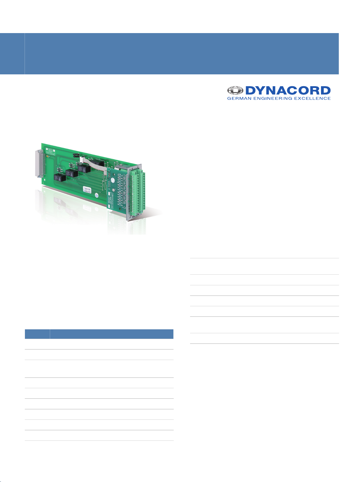
DCS 407R
www.dynacord.com
▪ 4 low frequency relays, 2 switch contacts each.
▪ Gold-plated double contacts for high level of
contact reliability.
▪ Pluggable connection terminals with screwed flange
for all contacts and coils.
The module is fitted on the back of the DCS 400 rack
plug-in board. The module is used to switch audio
signals (line levels) or for control purposes regardless
of the DCS 400 system.
Additional properties:
• Configure the audio distributor by separating the wire
jumpers.
• A monitor bus can be connected.
Parts included
No. Component
1 DCS 407R
2 Plug, 15-pin (Phoenix MC 1.5/15-STF-3.81 - 1827839)
Technical specifications
▪ 4 relay control LEDs.
Product dimensions (Width by
Height by Depth)
Net weight 163 g
Relay contacts
• Contacts 2 SPDT
• Contact material AgPd + 10μ Au
• Contact load (real) 1 A / 24 V DC
• Contact current max. 2 A
37.5 by 80.6 by 245 mm
0.5 A / 120 V DC
Operating voltage 24 V DC, -10%/+30%
Operating current
• Standby 24 V, 5.5 mA, 0.14 W
• Idle/Announcement/Alert 24 V, 42 mA, 1.01 W
Electromagnetical environment E1, E2, E3
Operating temperature -5 °C to 45 °C
Page 2
A11
B26
A10
A12
B25
B27
A8
B23
A7
A9
B22
B24
A5
B20
A4
A6
B19
B21
A2
B17
A1
A3
B16
B18
A14
A15
A13
B28
B29
B30
C
N
t
o
B
a
c
k
p
l
a
n
e
CLK1
CLK1_A
CLK2
CLK2_A
CLK3
CLK3_A
RES
RES_A
*RES
*RES_A
DATA1
DATA1_A
DATA2
DATA2_A
DATA3
DATA3_A
DATA4_A
DATA5
DATA5_A
DATA_SEL
EN1
EN1_A
EN2
EN2_A
EN3
EN3_A
EN4
EN4_A
EN5
EN5_A
EN6
EN6_A
EN7
EN7_A
EN8
EN8_A
+24V
GND
MON+
MON-
DATA4_SEL_A
2 | DCS 407R
Ordering information
DCS 407R
Order number F01U121782
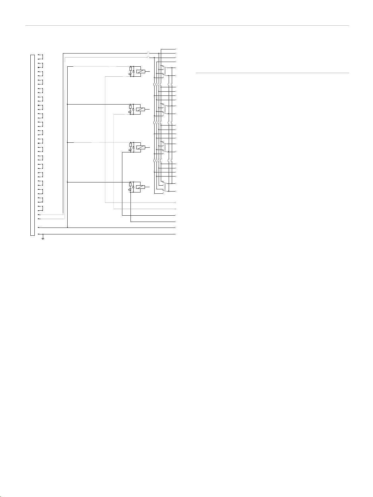
Block diagram
Installation/configuration notes
Installation information
On the DCS 400 rack plug-in board, slots 1–10 must
be occupied in ascending sequence (left to right)
without any gaps. Different module types can
otherwise be arranged in any sequence.
Exception: Slot 1 (far left) must always be occupied
with a DCS 801R control module or DCS 405R
extension module.
When assembling the device and installing the
connections, please comply with the standards VDE
0100 and EN 60065.
Connector
The scope of delivery for the device includes two 15pin connectors. Conductor cross-sections of 0.14 mm²
(AWG26) to 1.5 mm² (AWG16) can be used.
Recommended connecting cable: flexible CU strand,
LiY, 0.75 mm².
Certifications and approvals
Status as of November 2012:
• EN 50130-4
• EN 54-16
• EN 55103-1
• EN 55103-2
Page 3

3 | DCS 407R
Represented by:
Germany:
EVI Audio GmbH
Sachsenring 60
94315 Straubing
Germany
www.dynacord.com
© Bosch Security Systems 2013 | Data subject to change without notice
 Loading...