

DWT BM-110 T, BM-280 T, BM-300, BM-400 C, BM-400 Original Instructions Manual
...

www.dwt-pt.com
CH
DE
BR
PL
CZ
GR
RU
BY
UA
LT
Merit Link International AG
Switzerland
ML Meritlink Hardware Germany GmbH
Deutschland
DWT do Brasil Ferramentas Ltda
A. Mattes industrial products SA
Brasil
HANMAR
Polska
GARLAND distributor, s.r.o.
Czech republic
Ελλαδα
ООО "БОКС МУВИНГ"
Россия
ОДО "Планета ДВТ"
Беларусь
ТОВ "Eдіссон"
Україна
UAB "Balimpeksas"
Lietuva
[0041] 916000888 [0041] 916000888 info@dwt-pt.com
[0049] 3068055522 [0049] 3068055994 info@dwt-pt.de
[0055] 4121012600 técnico@dwt.com.br
[0048] 338587829 [0048] 338586100 serwis.ustron@hanmar.pl
[00420] 493523523 [00420] 493522916 garland@garland.cz
[0030] 2109851000 [0030] 2109839721 info@mattes.gr
[007] 8123321644 ofce@giper.tv
[00375] 175109545 [00375] 175109545 info@dwt.by
[0038] 563749060 [0038] 563749066 dwt@eds-group.dp.ua
[00370] 52444077 [00370] 52499280 balimpeks@is.lt
LV
MD
EG
IQ
LY
IR
KZ
DWT.LV
Latvija
BEM INNA SRL
Moldova
AL Hurria for Suppliers, Trading Agents Public
Import & Export
Egypt
Arkan Ali Mohammad Ali Mandalawi
Iraq
Bitrek Company
Libya
DWT Iran
Iran
ТОО "TECHNOSECTOR"
Қазақстан
[00371] 26655503 [00371] 67447509 birojs@htool.lv
[00373] 921180 [00373] 429368 masterbem@mail.ru
[0020] 033919328
[00964] 7702975399 [00964] 7702975399
[00218] 512611882 [00218] 51262812
[0098] 2163498 [0098] 2189787426 dwt.iran@gmail.com
[007] 7273748325 info@technosector.kz
2

Content / Sommaire / Содержание / Зміст / Мазмұны /
English
Explanatory drawings ............................................................................................................. pages
General safety rules, instructions manual ............................................................................. pages
Parts diagrams ...................................................................................................................... pages
Service centres ...................................................................................................................... pages
DWT warranty .......................................................................................................................... page
Warranty card and service cards ........................................................................................... pages
Français
Dessins explicatifs .................................................................................................................. pages
Recommandations générales de sécurité, mode d'emploi .................................................... pages
Schéma des pièces ............................................................................................................... pages
Centres d'assistance ............................................................................................................. pages
Garantie DWT .......................................................................................................................... page
Garantie coupon et cartes de service .................................................................................... pages
Русский
Пояснительные рисунки .............................................................................................. страницы
Общие указания по ТБ, инструкция по эксплуатации ............................................ страницы
Схемы запчастей ........................................................................................................ страницы
Сервисные центры ..................................................................................................... страницы
Гарантия DWT .............................................................................................................. страница
Гарантийный талон и сервисные талоны .............................................................. страницы
Украïнська
Пояснювальні малюнки ...................................................................................................сторінки
Загальні вказівки по ТБ, iнструкція з експлуатації ..................................................... сторінки
Схеми запчастин ............................................................................................................ сторінки
Сервісні центри .............................................................................................................. сторінки
Гарантія DWT ................................................................................................................. сторінки
Гарантійний талон i сервісні талони ...........................................................................сторінки
4 - 8
9 - 14
47 - 54
55 - 59
60
72 - 74
4 - 8
15 - 20
47 - 54
55 - 59
61
72 - 74
4 - 8
21 - 27
47 - 54
55 - 59
62
72 - 74
4 - 8
28 - 34
47 - 54
55 - 59
63 - 68
72 - 74
Қазақ тілі
Түсіндіргіш әлеміштер ....................................................................................................беттер
Жалпы қауіпсіздік жөніндегі ұсыныстар, пайдалану нұсқаулығы ................................... беттер
Бөлшектер тәсімі ........................................................................................................... беттер
Қызмет орталықтары ................................................................................................... беттер
DWT кепілдігі .......................................................................................................................... бет
Гарантиялы талон және қызмет көрсету карталары ...............................................беттер
.........................................................................................................................
...................................................................................................
...........................................................................................................................
...............................................................................................................................
.................................................................................................................................
........................................................................................................
3
4 - 8
35 - 40
47 - 54
55 - 59
69
72 - 74
4 - 8
41 - 46
47 - 54
55 - 59
70
72 - 74
45678

741763
742920
5
2.78
0,8-10
30
1-3/16"
10
1,9
25/64"
4.19
1/32"-25/64"
741756
742913
741749
742906
741732
742890
741022
742883
741015
742876
741008
742869
5
3.5
3.5
2.5
2.2
0.9
2.78
1.85
1.85
1.35
1.2
0.5
30
10
3.9
1,5-10
1-3/16"
1,77
25/64"
1/16"-25/64"
20
10
1,43
0,8-10
25/32"
25/64"
3.15
1/32"-25/64"
20
10
1,43
1,5-10
25/32"
25/64"
3.15
1/16"-25/64"
9
20
6
23/64"
10
25/32"
1/4"
1,06
1,5
25/64"
2.34
3.31
— — — — —
— — — — —
0,6-6
1/32"-1/4"
0,8-10
1/32"-25/64"
20
10
1,23
0,8-10
1/32"-25/64"
[mm]
[inches]
25/32"
[mm]
[inches]
25/64"
[mm]
[inches]
2.71
[kg]
[lbs]
] 0,55 1,93 6,87 1,44 1,44 3,71 3,71
2
127 V [Amps]
230 V [Amps]
[127 V ~50/60 Hz]
[230 V ~50/60 Hz]
Power tool specications
Drill BM-110 T BM-280 T BM-300 BM-400 BM-400 C BM-600 BM-600 C
Power tool code
Rated power [W] 110 280 300 400 400 600 600
Power output [W] 70 160 120 190 190 285 285
Amperage at voltage
- rst gear [RPM] 0-310 0-350 3800 0-3000 0-3000 0-2500 0-2500
- second gear [RPM] 0-1100 0-1400
No-load speed:
English
Turndown of rotation torque [Nm] 0,8-20 0,8-22
Chuck tightening range
Drilling output:
9
- wood
- steel
Weight
Safety class
Sound pressure [dB(A)] 66 84,3 80 82,7 82,7 84 84
Acoustic power [dB(A)] 77 95,3 91 93,7 93,7 95 95
Weighted vibration [m/s
Noise
information
Always wear ear protection if the sound
pressure exceed 85 dB(A).
Declaration of
conformity
We declare under our sole responsibility that the
product described under "Power tool specications" is
in conformity with all relevant provisions of the
directives 2006/42/EC including their amendments
and complies with the following standards: EN 60745-1,
EN 60745-2-1.
Managing director V.Kobzar
Merit Link International AG
Switzerland
Stabio, 09.09.2015
General
safety recommendations
CAUTION! Make sure you have read
and understood all recommendations.
Failure to observe the following recommendations may result in electric shock,
cause re and / or serious injuries. The term
"power tool", used in this manual refers to the
tools equipped with a power supply cord or a
battery.
Working space
• The workstation should be kept tidy and well-lit.
Disorder at the workstation and inadequate lighting
may result in accidents.
• Do not use power tools in environment exposed
to the risk of explosion, e.g. near ammable liquid
vapours, gases or ammable particles in the form of
dusts. During operation, sparks are generated, which
may ignite dust or vapours.
• Do not allow children and unauthorised persons near
places where operations with the use of an electric tool
are carried out. Third parties may distract the operator's
attention, and he may loose control over the tool.
Electric safety recommendations
• The tool plug should always be inserted to an
appropriate socket. This reduces the risk of electric
shock. Do not use plug adapters with grounding
contacts.
• Avoid touching grounded items, such as metal pipes,
heaters, cookers and refrigerators. If the worker's body
comes into contact with a grounded item, the danger of
electric shock increases.
• Protect the power tool against rain and moisture.
Penetration of water into the tool increases the danger
of electric shock.
• Do not use the power supply cable for purposes
other than designed. Under no circumstances should
one use the cable to carry the tool or pull it; also, it is
English
forbidden to switch off the tool by pulling the power
supply cable. Protect the cable against heating, contact
with kerosene-based bodies, with sharp edges or
mobile parts of the tool. A power cable that is damaged
or spliced increases the danger of electric shock.
• When working in open air, use extension cords
designed for this type of work, which will reduce the
danger of electric shock.
Personal protection recommendations
• Be cautious when working with power tools, and
carefully plan your actions. Do not use the tool when
fatigued, or under the inuence of drugs, alcohol or
medicines. Careless handling may result in serious
injuries.
• Use personal protection equipment. Always
wear protective goggles. When necessary, use
respirators, non-slipping boots, hard hats and
earplugs. The use of personal protection equipment
is one of the factors that reduce the risk of injuries.
• Avoid incidental activation of power tools. Before
inserting the plug, make sure that the power switch is in
OFF position. When carrying the tool, take your ngers
off the main switch, which will reduce the possibility of
incidental activation.
• Before switching on the tool, remove any wrenches
and other objects from its rotating parts. A wrench left
in the rotating unit may result in serious injuries.
• Do not apply excessive force, take a stable position
and always try to keep balance - this will facilitate
control over the tool.
• Do not wear loose clothes or freely-hanging
jewellery. Hair, parts of garment and gloves should
be protected against contact with moving parts of the
power tool.
• If the tool is equipped with a dust collection device,
make sure that the device has been activated and
used properly. Use of such devices helps reduce the
concentration of dust at the workstation.
Use and handling of power tools
• The persons with lowered psychophysical or mental
aptitudes as well as children can not operate the power
tool, if they are not supervised or instructed about use
of the power tool by a person responsible for their
safety.
• Do not overload the tool. Power tools are to be used
only in operations, to which they have been designed,
which will ensure safety and help achieve better
results.
• Do not use power tools with a damaged power
switch. A tool that cannot be switched on and off in a
controlled manner is potentially dangerous and must
be repaired immediately.
• Before adjustment operations, replacement of
attachments, and during storage, remove the power
tool plug from the mains socket. This eliminates the
risk of the tool being unintentionally activated.
• The tool should be stored out of children's reach.
Do not allow the use of power tools by persons who
have not read this manual and are inexperienced. In
the hands of an inexpert person, the tool may be dangerous both for the operator and his environment.
• Take proper care of the tool condition. Monitor the
axial run-out and stability of movable parts' joints, and
pay proper attention at any faults that may result in the
10
tool damage. Bad condition of power tools is a frequent
cause of accidents.
• Cutting tools should be kept clean and must be well-
sharpened. Cutting tools with sharp cutting edges,
which are properly xed reduce the risk of seizure and
facilitate the control over power tools.
• When using power tools and its accessories, follow
the instructions listed in this manual. During work with a
specic type of power tools, follow recommendations,
taking into account operational conditions and the type
of job performed.
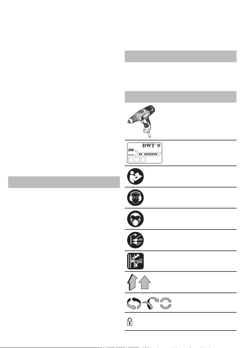
Symbol Meaning
Drill
Sections marked gray - soft
grip (with insulated surface)
Service of power tools
Your power tool should be serviced only by qualied
specialists, with the use of recommended spare parts.
This will guarantee labour safety, when your tool is
being applied.
Safety guidelines during
power tool operation
•
Avoid stopping an electric tool motor when loaded.
• Maintain a stable position while working, hold the
electric tool with two hands.
• Never remove any chips or fragments with your
electric tool's motor running.
• Before starting work, make sure where hidden
electric cables and water and gas pipes are situated.
Damaging the electric supply wiring or engineering
communications may cause a severe harm to the
operator's life and health.
• If the working schedule cannot exclude damaging
the main supply cables, they have to be de-energized.
• When working, follow the position of the power
supply cable. Avoid winding it around your legs or
arms.
• Use only sharp drills without defects - it will make
working with the power tool easier.
• The modication of the drills design and the use of
removable orices and accessories not envisaged for
this power tool is strictly forbidden.
• Do not apply excessive pressure when operating
the power tool - it can jam the drill and overload the
engine.
• Do not allow drills to jam in the material processed.
If this occurs, do not try to release them by means of
the power tool engine. This can put the power tool out
of order.
• Striking out drills jammed in the material processed
with a hammer or other objects is strictly forbidden -
metal fragments can hurt both the operator and the
people nearby.
• Avoid overheating your electric tool, when using it
for a long time.
• Never treat workpieces containing asbestos.
Asbestos is cosidered carcinogenic.
Symbols used in
the manual
Following symbols are used in the operation manual,
please remember their meanings. Correct interpretation
of the symbols will allow correct and safe use of the
power tool.
English
Serial number sticker:
BM ... - model;
XX - date of manufacture;
XXXXXXX - serial number.
Read all safety regulations
and instructions.
Wear safety goggles and ear
protectors.
Wear a dust mask.
Disconnect the power tool
from the mains before instal-
lation or adjustment.
Risk of damage to hidden
wiring or household service
lines.
Movement direction.
Rotation direction.
Locked.
Unlocked.
Prohibited.
Double insulation / protection class.
Attention. Warning of possible user health damage.
11
Symbol Meaning
A sign certifying that the
product complies with essential requirements of the
EU directives and harmonized EU standards.
Attention. Important.
Useful information.
Wear protective gloves.
Torque control position:
"Drilling".
Stepless speed control.
Do not dispose of the power
tool in a domestic waste
container.
power tool designation
Electric drills are used for drilling in steel, wood and
ceramics.
The ability to adjust the speed and availability of the
reverse mode allows the power tool to be used as a
screwdriver.
The area of the tool application can be expanded due
to use of additional accessories.
There is a possibility of a stationary installation of the
tool by use of some special accessories.
1
Keyless chuck *
2 Torque regulator
3 Step speed selector switch
4 Ventilation slots
5 Rotational direction switch
6 On / off switch
7 Light-emitting diode (LED)
8 Gear rim chuck *
9 Locking button for on / off switch
10 Drill chuck key *
11 Belt clip
12 Speed selector thumbwheel
13 Screw *
14 Magnetic holder *
15 Screwdriver bit *
DWT
Power tool
components
English
* Optional extra
Not all of the accessories illustrated or described
are included as standard delivery.
Installation and regulation
of power tool elements
Before carrying out any works on the power tool it
must be disconnected from the mains.
Do not draw up the fastening elements
too tight to avoid damaging the thread.
Mounting / dismounting / setting-up of
some elements is the same for all power
tool models, in this case specic models
are not indicated in the illustration.
Mounting / replacement of accessories (see g. 1)
With long-term use the drill bit may become very warm; use gloves to remove
it.
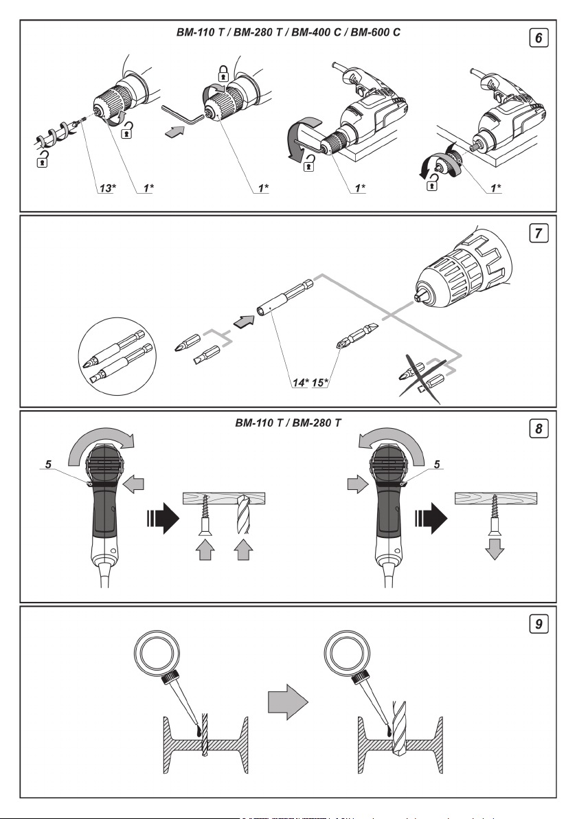
Gear rim chuck (see g. 1)
[BM-300, BM-400, BM-600]
• Release the cams grip with clamping wrench 10,
then rotate the quill of gear rim chuck 8 counter-
clockwise with your hand (see g. 1) until the cams
move apart at the distance allowing an accessory to
be mounted / replaced.
• Mount / replace an accessory.
• Rotate the quill of gear rim chuck 8 clockwise with
your hand in order to lock the accessory mounted. Do
not allow the accessory to become distorted.
• Tighten the cams of gear rim chuck 8 with clamping
wrench 10 applying a similar torque to each of the
three openings on the side surface of the chuck.
Keyless chuck (see g. 2)
[BM-110 T, BM-280 T, BM-400 C, BM-600 C]
• Open the jaws of the keyless chuck 1 - hold its rear
part with one hand and rotate its front part with the
other hand as it is shown in gure 2.
• Mount / replace the accessory.
• Tighten the keyless chuck 1 without skewing the
accessory as it is shown in gure 2.
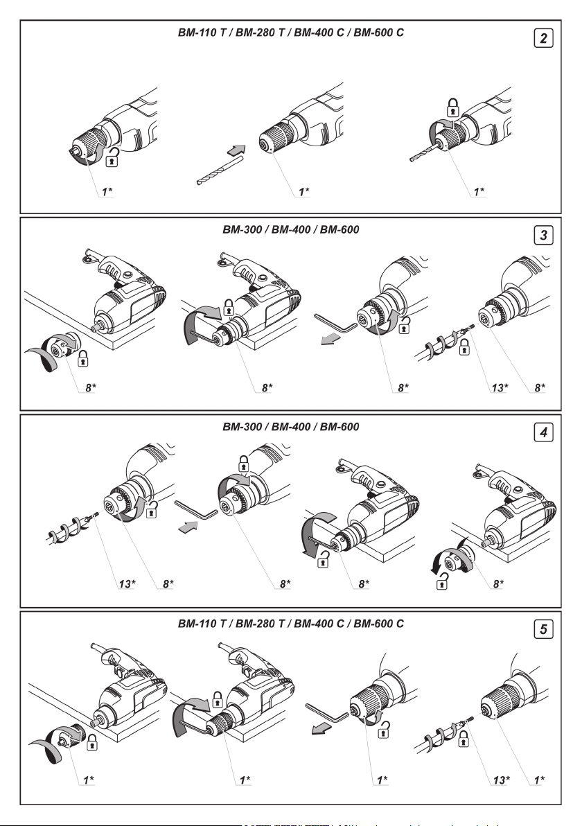
Mounting / dismounting of the drill chuck (see
g. 3-6)
• To mount the gear rim chuck 8, carry out the
operations in consecutive stages as it is shown in
gure 3.
• To dismount the gear rim chuck 8, carry out the
operations in consecutive stages as it is shown in
gure 4.
• The mounting or dismounting of keyless chuck 1 is
done is a similar way, see g. 5-6.
Attention: keep in mind that in the
process of mounting / dismounting of the
drill chuck the screw 13 has a left-hand
thread.
12

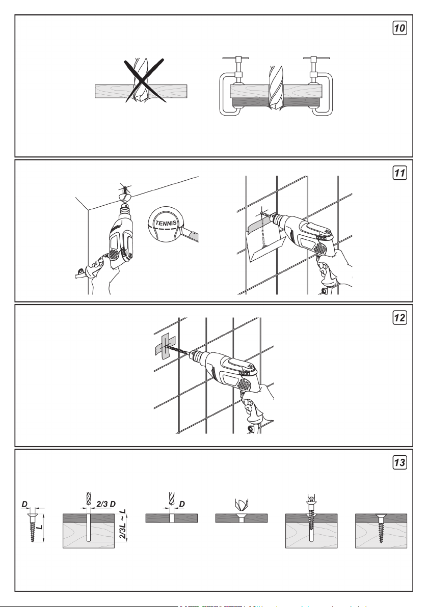
Screwdriver bit / magnetic holder (see g. 7)
When using the power tool as a screwdriver, use
magnetic holder 14 for reliable locking of screwdriver
bits 15 (see g. 7). A magnetic holder 14 is not needed
for extended screwdriver bits 15 (specially purposed
for screwdrivers).
Initial operating
of the power tool
Always use the correct supply voltage: the power
supply voltage must match the information quoted on
the power tool identication plate.
Switching the power
tool on / off
[BM-110 T, BM-280 T]
Make sure that the reverse switch 5 is not centred;
this blocks on / off switch 6.
Switching on:
Press on / off switch 6.
Switching off:
Release the on / off switch 6.
[BM-300, BM-400, BM-400 C, BM-600, BM-600 C]
Short-term switching on / off
To switch on, press and hold on / off switch 6, to switch
off - release it.
Long-term switching on / off
Switching on:
Push on / off switch 6 and lock it in the position with
locking button for on / off switch 9.
Switching off:
Push and release on / off switch 6.
Design features
of the power tool
Torque regulator
[BM-110 T, BM-280 T]
Rotate the regulator 2 in order to set one of the 18
torque values most suitable for the work performed.
It is recommended to set the torque
regulator 2 into the position "Drill" to perform
drilling.
Step speed selector switch
[BM-110 T, BM-280 T]
Attention: one can only change the
revolutions per minute range after the
engine fully stops.
In order to put in the rst gear, move the switch 3
forward. This mode is used for the fastening of screws
or for large diameter hole drilling.
English
In order to put in the second gear, move the
switch 3 back. This mode is used for speed drilling of
small diameter holes.
Stepless speed adjustment
Speed is controlled from 0 to maximum by
pressing force of on / off switch 6. Weak
pressing results in low revolutions, which
enable a smooth power tool switch-on.
Speed selector thumbwheel
[BM-400, BM-400 C, BM-600, BM-600 C]
Use speed control 12 to set required number of
revolutions.
• Push on / off switch 6 and lock it in the position with
locking button for on / off switch 9.
• Set the needed speed.
The required speed is dependent on the material and
can be determined with practical trials.
When operating your power tool at a low speed for a
long time, it has to be cooled down for 3 minutes. To
do it, set a maximum speed and leave your power tool
to run idle.
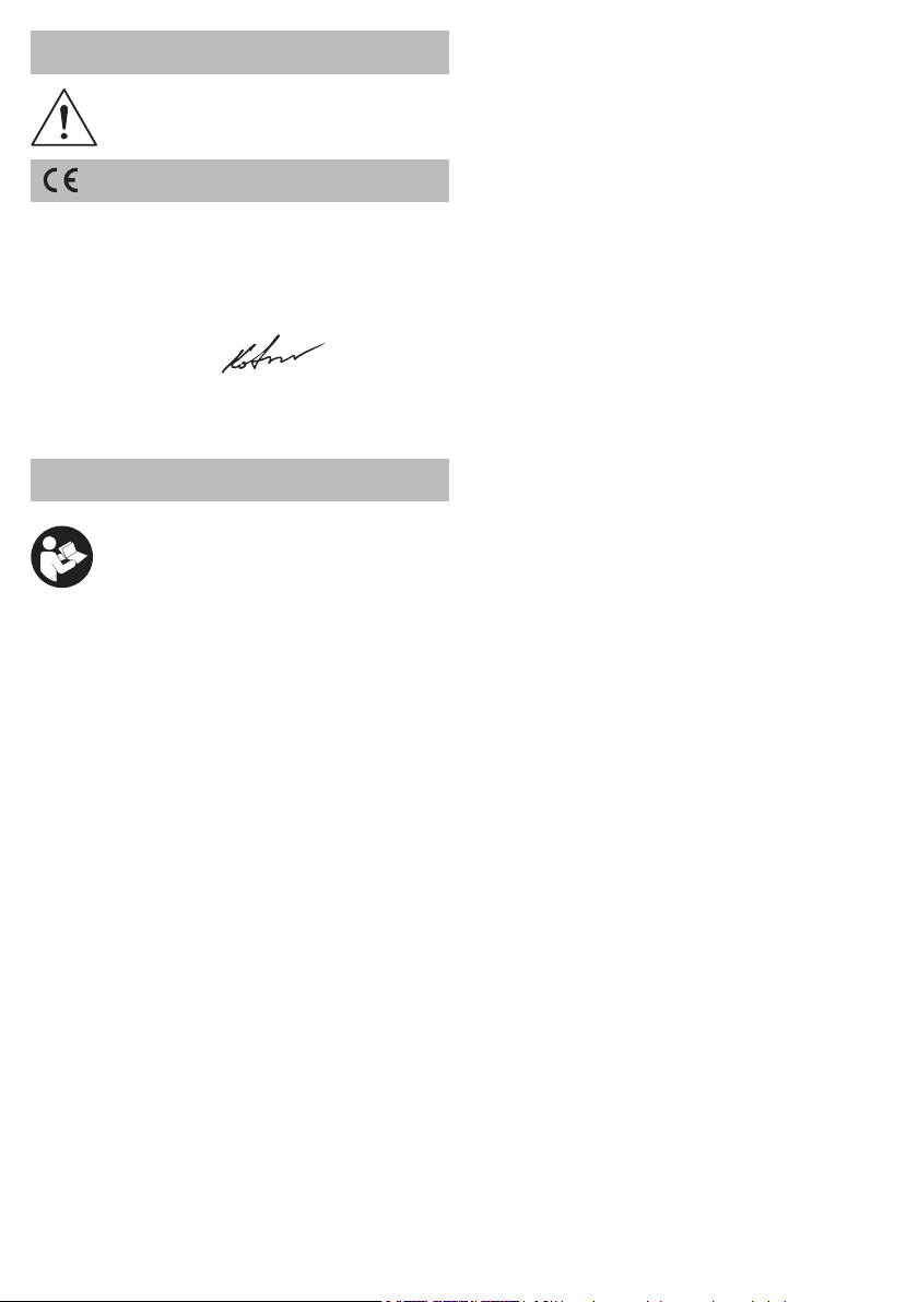
Changing the rotational directions (see g. 8)
Change the direction of rotation only after
a full stop of the motor, acting otherwise
may cause damage to the power tool.
[BM-300, BM-400, BM-400 C, BM-600, BM-600 C]
Rotation to the right (drilling, screwing in) - move
the rotational direction switch 5 to the right.
Rotation to the left (unscrewing) - move the
rotational direction switch 5 to the left.
[BM-110 T, BM-280 T]
Clockwise rotation (drilling, fastening of screws) -
move the rotational direction switch 5 to the left as it is
shown in g. 8.
Counter clockwise rotation (unscrewing the
screws) - move the rotational direction switch 5 to the
right as it is shown in g. 8.
Spindle automatic locking
[BM-110 T, BM-280 T]
If the on / off switch 6 is not pressed, the spindle of the
power tool is locked this enables to use the power tool
as an ordinary screwdriver (for example it can be used
to tighten manually screws or bolts).
Light-emitting diode
[BM-280 T]
When the power tool is connected to the mains, the
LED 7 operates in an indicator mode (low light) and
shows that the power tool is ready to be turned on.
When you press the on / off switch 6, the LED 7
operates in a mode of light (strong light) it allows you
to work in low light conditions.
13

Recommendations
on the power tool operation
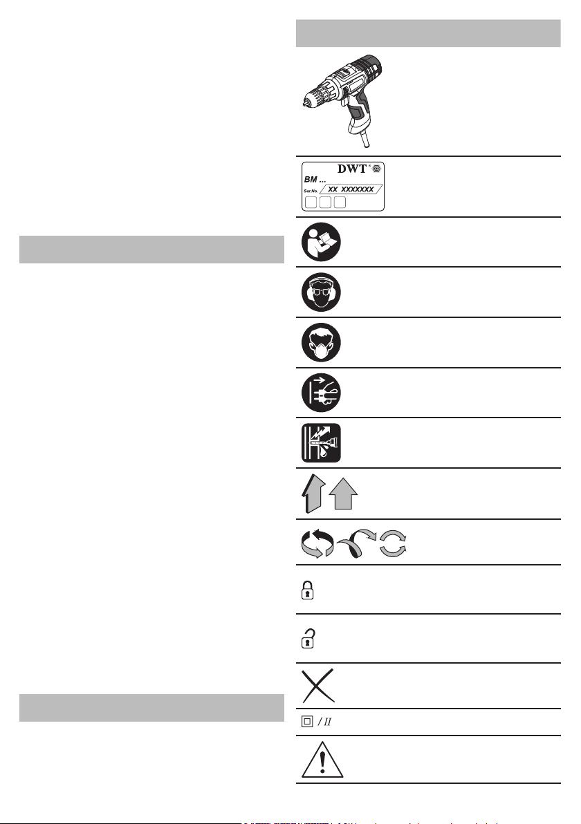
Drilling (see g. 9-12)
• Grease the drill bit regularly when drilling holes in met-
als (except drilling non-ferrous metals and their alloys).
• When drilling hard metals, apply more force to the
power tool and lower the rotation speed.
• When drilling large diameter holes in metal, rst
drill a hole with a smaller diameter and ream it till the
necessary diameter (see. g. 9).
• In order to avoid splitting of the surface at an exit
point of a drill bit when drilling holes in wood, follow the
instructions shown in gure 10.
• In order to decrease dust production when drilling
holes in walls and ceilings, take actions indicated in
gure 11.
• When drilling holes in glazed ceramic tiles, in order
to improve the drill centering accuracy and to save the
glaze from damage, apply adhesive tape to the presumed hole center and drill after that (see g. 12). Start
drilling at lower speed increasing it as the hole deepens.
Screwing the screws (see g. 13)
• To make fastening of screws easier and in order to
prevent cracking of the work pieces, rst drill a hole
with a diameter equal to 2/3 of a diameter of the screw.
• If you are connecting work pieces with the help of
screws, in order to achieve durable joint without getting cracks, fracturing or layering, take actions shown
in gure 13.
Power tool maintenance /
preventive measures
Before carrying out any works on the power tool it
must be disconnected from the mains.
Cleaning of the power tool
An indispensable condition for a safe long-term
exploitation of the power tool is to keep it clean.
Regularly ush the power tool with compressed air
thought the ventilation slots 4.
After-sales Service and Application Service
Our after-sales service responds to your questions
concerning maintenance and repair of your product as
well as spare parts. Information about service centers,
parts diagrams and information about spare parts can
also be found under: www.dwt-pt.com.
Transportation
of the power tools
•
Categorically not to drop any mechanical impact on
the packaging during transport.
• When unloading / loading is not allowed to use
any kind of technology that works on the principle of
clamping packaging.
Environmental
protection
Recycle raw materials instead of
disposing as waste.
Power tool, accessories and packaging should be
sorted for environment-friendly recycling.
The plastic components are labelled for categorized
recycling.
These instructions are printed on recycled paper
manufactured without chlorine.
The manufacturer reserves the possibility to introduce changes.
English
14

741763
742920
5
2.78
0,8-10
30
1-3/16"
10
1,9
25/64"
4.19
1/32"-25/64"
741756
742913
741749
742906
741732
742890
741022
742883
741015
742876
741008
742869
5
2.78
3.5
1.85
3.5
1.85
2.5
1.35
2.2
1.2
0.9
0.5
127 V [A]
230 V [A]
] 0-310 0-350 3800 0-3000 0-3000 0-2500 0-2500
-1
— — — — —
] 0-1100 0-1400
-1
— — — — —
1,5-10
1/16"-25/64"
0,8-10
1/32"-25/64"
1,5-10
1/16"-25/64"
0,6-6
1/32"-1/4"
0,8-10
1/32"-25/64"
0,8-10
1/32"-25/64"
[mm]
[pouces]
30
1-3/16"
20
25/32"
20
25/32"
9
23/64"
20
25/32"
20
25/32"
[mm]
[pouces]
10
25/64"
10
25/64"
10
25/64"
6
1/4"
10
25/64"
10
25/64"
[mm]
[pouces]
3.9
1,77
1,43
3.15
1,43
3.15
1,06
2.34
1,5
3.31
1,23
2.71
[kg]
[lbs]
0,55 1,93 6,87 1,44 1,44 3,71 3,71
]
2
[127 V ~50/60 Hz]
[230 V ~50/60 Hz]
- première vitesse [min
Spécications de l’outil électrique
Perceuse BM-110 T BM-280 T BM-300 BM-400 BM-400 C BM-600 BM-600 C
Code de l’outil électrique
Puissance absorbée [W] 110 280 300 400 400 600 600
Puissance de sortie [W] 70 160 120 190 190 285 285
Ampérage tension
Régime à vide:
- seconde vitesse [min
Couple de rotation [Nm] 0,8-20 0,8-22
Français
15
- bois
Plage de resserrement du mandrin
Puissance de perçage:
- acier
Poids
Classe de protection
Pression acoustique [dB(A)] 66 84,3 80 82,7 82,7 84 84
Puissance acoustique [dB(A)] 77 95,3 91 93,7 93,7 95 95
Vibration [m/s
Bruit
d'information
Portez toujours des protections pour les
oreilles (casque) lorsque le niveau de
pression acoustique est supérieur
à 85 dB(A).
Déclaration
de conformité
Nous declarons sous notre propre responsabilite que
le produit decrit sous "Spécications de l'outil
électrique" est en conformite avec toutes les
dispositions des directives 2006/42/EC, et leurs
modications ainsi qu’avec les normes suivantes :
EN 60745-1, EN 60745-2-1.
Le directeur général V.Kobzar
Merit Link International AG
Suisse
Stabio, 09.09.2015
Recommandations générales
de sécurité
AVERTISSEMENT! Assurez-vous que
vous avez lu et compris toutes les
recommandations. La nonobservation
des recommandations suivantespeut
conduire à une décharge électrique, un incendie
et / ou de graves blessures. Le terme "outil
électrique" utilisé dans ce manuel fait allusion
aux outils équipés d'un cordon d'alimentation
électrique ou d'une batterie.
Espace de travail
• L'espace de travail devrait toujours être bien rangé
et bien éclairé. Du désordre dans l'espace de travail
et un éclairage insufsant peuvent conduire à des
accidents.
• Ne pas utiliser d'outils électriques dans un environ-
nement sujet au risque d'explosion, par ex. à proximité
de vapeurs liquides inammables, de gaz ou de particules inammables sous forme de poussières. Pen-
dant l'opération, les étincelles sont produites, ce qui
pourrait enammer la poussière ou les vapeurs.
• Ne pas laisser des enfants et des personnes
non autorisées s'approcher des endroits où sont
effectuées des opérations avec un outil électrique. Des
personnes extérieures pourraient distraire l'attention
de l'opérateur et il pourrait perdre le contrôle de l'outil.
Recommandations concernantla sécurité
électrique
• La prise de courant de l'outil doit toujours être insérée
dans une prise appropriée. Cela réduit le risque de
décharge électrique. Ne pas utiliser d'adaptateurs de
prise de courant avec des prises de mise à la terre.
• Éviter de toucher des articles reliés à la terre, comme
des tuyaux métalliques, des radiateurs, des cuisinières
et des réfrigérateurs. Si le corps de l'ouvrier entre du
contact avec un article relié à la terre, le danger de
décharge électrique augmente.
• Protégez l'outil électrique contre la pluie et l'humidité.
Si de l'eau pénètre dans l'outil, cela augmente le
danger de décharge électrique.
• Ne pas utiliser le câble d'alimentation électrique pour
un but autre que celui pour lequel il est conçu. Sous
aucune circonstance le câble ne doit être utilisé pour
porter ou tirer l'instrument; ne jamais non plus éteindre
l'outil en tirant sur le câble d'alimentation électrique.
Protéger le câble contre la chaleur, le contact avec des
corps à base de pétrole, avec des bords pointus ou
les parties mobiles de l'outil. Un câble d'alimentation
endommagé ou entortillé augmente le danger de
décharge électrique.
• Lors du travail en plein air, utiliser des rallonges
conçues pour ce type de travail, ce qui réduira le
danger de décharge électrique.
Recommandations de protection personnelle
• Soyez prudent lorsque vous travaillez avec des
outils électriques et planiez soigneusement vos
actions. Ne vous servez pas de l'outil lorsque vous
êtes fatigué ou sous l'inuence de drogues, d'alcool
ou de médicaments. Une manipulation négligente peut
conduire à de graves blessures.
• Utilisez un équipement de protection personnelle.
Portez toujours des lunettes de protection. Si
nécessaire, utilisez un respirateur, des bottes
antidérapantes, un casque et des protèges-tympan.
L'utilisation d'un équipement de protection personnelle
est un des facteurs qui réduit le risque de blessures.
• Évitez de mettre accidentellement en marche
l'outil électrique. Avant d'insérer la prise de courant,
assurez-vous que l'outil est en position OFF. Lorsque
vous portez l'outil, retirez vos doigts de l'interrupteur
de mise en marche, cela réduira la possibilité de mise
en marche accidentelle.
• Avant d'allumer l'outil, enlevez toute clé et autres
objets laissé dans ses parties rotatives. Une clé
oubliée dans l'unité rotative peut conduire à de graves
blessures.
• Ne forcez pas trop, prenez une position ferme et
essayez toujours de garder l'équilibre; cela facilitera
votre contrôle sur l'outil.
• Ne portez pas de vêtements lâches ou de bijoux qui
pendent. Les cheveux, les parties de vêtement et les
gants devraient être protégés contre le contact avec
les parties mobiles de l'outil électrique.
• Si l'outil est équipé d'un accessoire ramasse-
poussière, assurez-vous que l'accessoire est activé et
utilisé correctement. L'utilisation de tels accessoires
permet de réduire la concentration de la poussière
dans l'espace de travail.
Utilisation et emploi des outils électriques
• Les personnes physiquement ou mentalement
handicapées, ainsi que les enfants, ne peuvent utiliser
cet outil que sous contrôle ou selon instructions des
personnes responsables de leur sécurité.
• Ne surchargez pas l'outil. Les outils électriques
ne doivent être utilisés que pour des opérations
pour lesquelles ils ont été conçus, ce qui garantira
que la sécurité et permettra d'accomplir de meilleurs
résultats.
• N'utilisez pas d'outils électriques avec un interrup-
teur de mise en marche endommagé. Un outil qui ne
peut pas être allumé et éteint de manière contrôlée est
Français
16
potentiellement dangereux et doit être réparé immédiatement.
• Avant les opérations de réglage, de remplacement
des accessoires et pendant l'entreposage, débranchez
la prise de l'outil électrique. Cela élimine le risque de
mise en marche involontaire de l'outil.
• L'outil devrait être entreposé hors de portée des
enfants. Ne pas laisser des personnes qui n'ont pas
lu ce manuel se servir de l'outil électrique. Dans les
mains d'une personne inexpérimentée, l'outil peut
être dangereux à la fois pour l'utilisateur et pour son
environnement.
• Prenez bien soin de l'état de l'outil. Surveillez l'usure
des axiaux et la stabilité des articulations des parties mobiles et faites attention aux défauts qui peuvent conduire
à l'endommagement de l'outil. Un outil électrique en
mauvais état est une cause fréquente d'accidents.
• Les instruments coupants devraient être gardés
propres et bien aiguisés. Les instruments coupants dont
les lames sont bien aiguisées et qui sont correctement
attachées réduisent le risque de grippage et facilitent
le contrôle sur les outils électriques.
• Lorsque vous utilisez des outils électriques et des
accessoires, suivez les instructions données dans ce
manuel. Pendant le travail avec un type spécique
d'outil électrique, suivez les recommandations, en
tenant compte des conditions opérationnelles et du
type de travail effectué.
Service des outils électriques
L'entretien de votre outil électrique ne devrait être
coné qu'à des spécialistes qualiés, avec l'utilisation
de pièces de rechange recommandées. Cela garantira
la sécurité de la main-d'œuvre appliquée à votre
instrument.
Directives de sécurité pendant l'utilisation de
l'outil électrique
• Il est formellement déconseillé de frapper sur des
mèches coincées dans le matériau traité avec un marteau ou tout autre objet - les fragments en métal pourraient blesser l'opérateur ou les personnes à proximité.
• Évitez de faire surchauffer votre outil électrique en
l'utilisant de façon prolongée.
• Ne pas travailler les matériaux contenant de l'as-
beste. L'asbeste possède les propriétés cancérigènes.
Les symboles utilisés dans
le manuel d’utilisation
Le manuel d’utilisation utilise les symboles ci-dessous.
Pensez à lire attentivement leur signication. La bonne
interprétation des symboles permet de bien utiliser
l’instrument en toute sécurité.
Symbole Légende
Perceuse
Les zones grisées représen-
tent une applique molle (à la
surface isolée).
Etiquette avec le numéro
d’usine:
BM ... - modèle;
XX - date de fabrication;
XXXXXXX - numéro d’usine.
Lisez attentivement toutes
les consignes de sécurité et
les instructions.
•
Évitez d'arrêter le moteur d'un outil électrique
lorsqu'il est sous charge.
• Gardez une position ferme en travaillant, tenez
l'outil électrique à deux mains.
• N'enlevez jamais les éclats ou fragments sur votre
outil électrique lors qu'il est en marche.
• Avant de commencer un travail, assurez-vous
de savoir où se trouvent les câbles électriques
et les conduites d'eau et de gaz cachés. Le fait
d'endommager le l d'alimentation électrique ou la
construction mécanique peut entraîner des blessures
graves ou mettre la vie de l'opérateur en danger.
• Si le programme de travail ne peut pas exclure le fait
d'endommager les câbles d'alimentation principaux,
ceux-ci doivent être mis hors tension.
• Lorsque vous travaillez, suivez la position du câble
d'alimentation électrique. Évitez de l'enrouler autour
de vos jambes ou de vos bras.
• N'utiliser que des mèches aiguisées et sans défauts,
cela facilitera le travail de l'outil électrique.
• Il est formellement déconseillé de modier la conception des mèches et d'utiliser des orices amovibles et
des accessoires non prévus pour cet outil électrique.
• Ne pas appliquer de pression excessive lors de
l'utilisation de l'outil électrique - cela pourrait bloquer la
perceuse et surcharger le moteur.
• Ne pas laisser les mèches se bloquer dans le maté-
riau traité. Si cela se produit, ne pas essayer de les
libérer au moyen du moteur de l'outil. Cela risquerait
de l'endommager.
Français
Portez les lunettes et les
casques de protections.
Portez le masque antipoussière.
Avant les travaux de montage et de réglage, débran-
chez l’instrument du réseau
électrique.
Risque d’endommagement
de la canalisation électrique
cachée ou des conduites
principales de distribution.
Sens du mouvement.
Sens de la rotation.
Bloqué.
17

Symbole Légende
Débloqué.
Action interdite.
Double isolation / classe de
protection.
Attention. Avertissement du
préjudice corporel éventuel
pour l’utilisateur.
Signe certiant que l’article
correspond aux directives
CE et aux standards harmonisés de l’Union Euro-
péenne.
Attention. Information importante.
Information utile.
Portez les gants de protection.
Position du régulateur
du moment de torsion :
" Perçage ".
Régulation de vitesse sans
gradation.
Ne jetez pas l’outillage électrique avec les déchets mé-
nagers.
Désignation de l'outil électrique
Les perceuses électriques sont utilisées pour percer
dans l'acier, le bois et la céramique.
Le réglage de la vitesse et la fonction marche arrière
permettent d'utiliser l'outil comme un tournevis.
La portée d'utilisation de l'outil peut être élargie en
employant des accessoires supplémentaires.
Il est possible d'installer l'outil de façon xe (grâce à
des accessoires spéciaux).
1
Mandrin auto-serrant *
2 Régulateur de couple
DWT
Composants
de l'outil électrique
Français
3 Sélecteur de vitesse étape par étape
4 Fentes d'aération
5 Inverseur de sens de marche
6 Interrupteur marche / arrêt
7 Voyant LED
8 Mandrin de perçage à couronne dentée *
9 Bouton de blocage de l'interrupteur marche / arrêt
10 Clé pour le mandrin de perçage *
11 Clip pour ceinture
12 Molette de sélection de vitesse
13 Vis *
14 Aimant de retenue *
15 Embout de tournevis *
* Accessoires
Une partie des accessoires représentés et décrits
ne gurent pas dans la livraison.
Installation et réglage
des éléments de l'outil électrique
Avant de commencer à travailler avec l'outil
électrique, s'assurer qu'il est débranché.
Ne pas trop serrer les xations an
d'éviter tout endommagement du letage.
Le montage / démontage / réglage de
certains éléments est le même que pour
tous les modèles d'outils électriques;
dans ce cas, les modèles spéciques ne
sont pas indiqués sur l'illustration.
Monter / remplacer les accessoires (voir la g. 1)
Après une utilisation prolongée, le
foret de la perceuse peut être échauffé;
munissez-vous de gants pour le retirer.
Mandrin de perçage à couronne dentée (voir la
g. 1)
[BM-300, BM-400, BM-600]
• Libérer la prise des cames à l'aide de la clé de
serrage 10, tourner ensuite le fourreau du mandrin de
couronne 8 dans le sens inverse des aiguilles d'une
montre avec la main (voir image 1) jusqu'à ce que les
cames se soient écartées d'une distance permettant
de monter / remplacer un accessoire.
• Monter / remplacer un accessoire.
• Tourner le fourreau du mandrin de couronne 8 dans
le sens des aiguilles d'une montre avec la main pour
verrouiller l'accessoire monté en position. Ne pas aller
jusqu'à tordre l'accessoire.
• Serrer les cames du mandrin de couronne 8 à l'aide
de la clé de serrage 10 en appliquant un moment de
torsion similaire à chacune des trois ouvertures de la
surface de l'embrayage.
Mandrin auto-serrant (voir la g. 2)
[BM-110 T, BM-280 T, BM-400 C, BM-600 C]
• Ouvrir le mandrin sans clavette 1 - tenir l'arrière
d'une main et de l'autre main effectuer une rotation de
la partie avant comme indiqué à la gure 2.
18
• Monter / remplacer l'accessoire.
• Serrer le mandrin sans clavette 1 sans déformer
l'accessoire comme indiqué à la gure 2.
Montage / démontage du mandrin porte-foret (voir
les g. 3-6)
• Pour installer le mandrin de couronne 8 suivre les
pas successifs comme cela est montré sur la gure 3.
• Pour démonter le mandrin de couronne 8, suivre
les pas successifs comme cela est montré sur la
gure 4.
• Montage ou démontage du mandrin auto-serrant 1
s'effectue de pareille manière, voir les g. 5-6.
Attention: au cours du montage et du
démontage du mandrin porte-foret il faut
faut prendre en considération le fait que
la vis 13 possède le letage à gauche.
Embout de tournevis / aimant de retenue (voir la
g. 7)
Si l'outil électrique est utilisé comme tournevis, utiliser
l'aimant de retenue 14 pour un verrouillage sûr de
l'embout de tournevis 15 (voir la g. 7). L'aimant de
retenue 14 n'est pas nécessaire pour les embouts de
tournevis prolongés 15 (spécialement conçus pour les
tournevis).
Première utilisation
de l'outil électrique
Toujours utiliser la bonne tension d'alimentation:
la tension d'alimentation doit correspondre à celle
indiquée sur la plaque d'identication de l'outil
électrique.
Mettre en marche / arrêter
l'outil électrique
[BM-110 T, BM-280 T]
S'assurer que la position de l'interrupteur 5
n'est pas au centre; cela permet de verrouiller
l'interrupteur marche / arrêt 6.
Activer:
Appuyer sur l'interrupteur marche / arrêt 6.
Désactiver:
Relâcher l'interrupteur marche / arrêt 6.
[BM-300, BM-400, BM-400 C, BM-600, BM-600 C]
Marche / arrêt à court terme
Pour mettre en marche, presser et maintenir le
sélecteur on / off 6, pour arrêter - le relâcher.
Marche / arrêt à long terme
Activer:
Pousser le sélecteur on / off 6 et le bloquer en posi-
tion à l'aide du bouton de blocage du sélecteur on /
off 9.
Désactiver:
Pousser et relâcher le sélecteur on / off 6.
Français
Caractéristiques de l'outil
électrique
Régulateur de couple
[BM-110 T, BM-280 T]
Effectuer une rotation du régulateur 2 pour lui affecter
l'une des 18 valeurs pour le régulateur de couple.
Il est recommandé de mettre le régulateur
de couple 2 sur la position "Perceuse" pour
commencer à percer.
Sélecteur de vitesse étape par étape
[BM-110 T, BM-280 T]
Attention: il n'est possible de changer
les révolutions par minute qu'après avoir
complètement arrêté le moteur.
Pour mettre en première vitesse, poussez sur
l'interrupteur 3. On utilise ce mode lorsqu'on enfonce
des vis ou pour percer des trous de forts diamètres.
Pour mettre en deuxième vitesse, remettre
l'interrupteur 3 sur la position précédente. Ce mode
est utilisé pour percer des petits trous à grande vitesse.
Ajustage de vitesse continue
La vitesse est réglable de 0 à maximum
en appuyant sur l'interrupteur marche /
arrêt 6. Appuyez faiblement pour obtenir de
révolutions basses, ce qui permet une mise
en marche sans à-coup de l'outil électrique.
Molette de sélection de vitesse
[BM-400, BM-400 C, BM-600, BM-600 C]
Servez vous de la commande de vitesse 12 pour
ajuster la vitesse nécessaire.
• Pousser le sélecteur on / off 6 et le bloquer en
position à l'aide du bouton de blocage du sélecteur
on / off 9.
• Sélectionnez la vitesse désirée.
La vitesse nécessaire est fonction du matériau et sera
déterminée par des essais.
Si votre l'outil électrique fonctionne à faible vitesse
pendant longtemps, vous devez le laisser refroidir
pendant 3 minutes. Pour ce faire, réglez sur vitesse
maximale et laisser votre l'outil électrique tourner à
vide.
Inversion du sens de marche (see g. 8)
Modier la direction de la rotation uni-
quement après l'arrêt complet du moteur, ne pas respecter cette procédure
peut causer des dommages à l'outil électrique.
19

[BM-300, BM-400, BM-400 C, BM-600, BM-600 C]
Rotation à la droite (perçage, vissage) - tourner le
sélecteur rotatif 5 vers la droite.
Rotation à gauche (dévissage) - tourner le sélecteur
rotatif 5 vers la gauche.
[BM-110 T, BM-280 T]
Rotation dans le sens des aiguilles d'une montre
(percer, xer des vis) - mettre l'interrupteur 5 à gauche
comme indiqué à la gure 8.
Rotation dans le sens inverse des aiguilles d'une
montre (dévisser) - mettre l'interrupteur 5 à droite
comme indiqué à la gure 8.
Verrouillage automatique de la fusée
[BM-110 T, BM-280 T]
Si l'interrupteur on / off 6 n'est pas enfoncé, la fusée
de l'outil électrique est verrouillée ce qui permet d'utiliser l'outil comme un tournevis ordinaire (ll peut, par
exemple, être utilisé pour visser des vis ou des boulons à la main).
Diode lumineuse
[BM-280 T]
Quand l'outil électrique est raccordé au secteur, la
LED 7 fonctionne en mode indicateur (lumière faible)
et indique que l'outil électrique est prêt à être mis en
marche.
Quand vous pressez l'interrupteur on / off 6, la LED 7
fonctionne en mode éclairage (lumière forte) - elle vous
permet de travailler sous un faible éclairage.
centrage du forage et éviter d'endommager la glaçure,
appliquez du ruban adhésif au centre de trou que vous
voulez percer puis percez (voir la g. 12). Commencer
à percer à la vitesse la plus faible puis l'augmenter au
fur et à mesure que le trou s'approfondit.
Vissage des vis (voir la g. 13)
• Pour faciliter la xation des vis et an de prévenir
tout risque de ssure des pièces, percer dans un
premier temps un trou dont le diamètre équivaut au
2/3 du celui de la vis.
• Si vous assemblez des pièces à l'aide de vis, pour
ne pas ssurer, briser ou rayer le support, suivre les
instructions de la gure 13.
Entretien de l'outil électrique /
mesures préventives
Avant de commencer à travailler avec l'outil
électrique, s'assurer qu'il est débranché.
Nettoyage de l'outil électrique
Un critère indispensable pour utiliser le l'outil électrique
sur le long terme est de le nettoyer régulièrement.
Chasser régulièrement les poussières de l'outil électrique en utilisant de l'air comprimé dans chaque trou 4.
Services après-vente et d'application
Notre service après-vente répond à vos questions
concernant l'entretien et la réparation de votre
appareil et de ses pièces de rechange. Des infor-
mations sur les centres d’entretien, les schémas
des pièces de rechange et les pièces de rechange
sont également disponibles à l’adresse suivante :
www.dwt-pt.com.
Recommandations pour utilisation de l'outil
Perçage (voir les g. 9-12)
• Lubrier le foret de la perceuse régulièrement
lorsque vous percez des trous dans des supports
métalliques (excepté les supports non ferreux et leurs
alliages).
• Lors du perçage de métaux lourds, forcer un peu
plus sur l'outil électrique et réduire la vitesse de rotation.
• Lors du perçage de trous de grand diamètre dans
du métal, percer dans un premier temps un trou de
plus petit diamètre puis élargir jusqu'au diamètre voulu
(voir la g. 9).
• Pour éviter de fendre la surface des matériaux en
bois avec le foret de la perceuse, veuillez suivre les
instructions de la gure 10.
• Pour limiter les poussières lors du perçage des trous
dans des murs ou des plafonds, suivez les instructions
de la gure 11.
• Lorsque vous percez des trous dans des carreaux
céramique vitriés, an d'améliorer l'exactitude de
électrique
Le fabricant se réserve le droit d'apporter des changements.
Français
Transport des
outils électriques
•
Éviter strictement tout impact mécanique sur
l'emballage pendant le transport.
• Lors du déchargement / chargement, il est interdit
d’utiliser tout type de technologie fonctionnant sur le
principe de serrage de l’emballage.
Protection
de l'environnement
Récupération des matières premières
plutôt qu’élimination des déchets.
Séparer l'outil électrique, les accessoires et l'emballage
pour un recyclage écologique.
Nos pièces plastiques ont ainsi été marquées en vue
d’un recyclage sélectif des différents matériaux.
Ce manuel d’instructions a été fabriqué à partir d’un
papier recyclé blanchi en l’absence de chlore.
20

741763
742920
5
2.78
0,8-10
30
1-3/16"
10
1,9
25/64"
4.19
1/32"-25/64"
741756
742913
741749
742906
741732
742890
741022
742883
741015
742876
741008
742869
5
3.5
3.5
2.5
2.2
0.9
2.78
1.85
1.85
1.35
1.2
0.5
] 0-310 0-350 3800 0-3000 0-3000 0-2500 0-2500
-1
— — — — —
] 0-1100 0-1400
-1
— — — — —
[Нм] 0,8-20 0,8-22
1,5-10
1/16"-25/64"
0,8-10
1/32"-25/64"
1,5-10
1/16"-25/64"
0,6-6
1/32"-1/4"
0,8-10
1/32"-25/64"
0,8-10
1/32"-25/64"
[мм]
30
1-3/16"
20
25/32"
20
25/32"
9
23/64"
20
25/32"
20
25/32"
[мм]
10
25/64"
10
25/64"
10
25/64"
6
1/4"
10
25/64"
10
25/64"
[мм]
1,77
1,43
1,43
1,06
1,5
1,23
[кг]
3.9
3.15
3.15
2.34
3.31
2.71
] 0,55 1,93 6,87 1,44 1,44 3,71 3,71
2
Технические характеристики электроинструмента
Электродрель BM-110 T BM-280 T BM-300 BM-400 BM-400 C BM-600 BM-600 C
[127 В ~50/60 Гц]
[230 В ~50/60 Гц]
Код электроинструмента
Номинальная мощность [Вт] 110 280 300 400 400 600 600
Выходная мощность [Вт] 70 160 120 190 190 285 285
127 В [A]
230 В [A]
- первая передача [мин
Сила тока при напряжении
Число оборотов холостого хода
- вторая передача [мин
Диапазон изменения крутящего
Русский
21
[дюймы]
момента
Диапазон зажима сверлильного
патрона
Максимальный диаметр сверления:
[дюймы]
- дерево
- сталь
[дюймы]
[фунты]
Вес
Класс безопасности
Звуковое давление [dB(A)] 66 84,3 80 82,7 82,7 84 84
Акустическая мощность [dB(A)] 77 95,3 91 93,7 93,7 95 95
Вибрация [м/с
Информация о
шуме
Носить приспособление для защиты
органов слуха при уровне звукового
давления свыше 85 dB(A).
Соответствия
требуемым нормам
Мы заявляем под нашу единоличную ответственность, что описанный в разделе "Технические характеристики электроинструмента" продукт
отвечает всем соответствующим положениям
Директив 2006/42/EC, включая их изменения, а
также следующим нормам: EN 60745-1,
EN 60745-2-1.
Директор В.Кобзарь
Merit Link International AG
Швейцария
Stabio, 09.09.2015
Общие указания по технике
безопасности
ВНИМАНИЕ! Прочитайте все рекомендации. Нарушение нижеизложенных рекомендаций может повлечь
за собой поражение электрическим
током, быть причиной пожаров и / или серьезных травм. Термин "электроинструмент"
встречающийся в данной инструкции, подразумевает электроинструмент оснащенный
либо токоведущим кабелем, либо аккумуляторной батареей.
Рабочее пространство
• Содержите рабочее место в чистоте и обеспечьте хорошее освещение. Беспорядок на рабочем месте и недостаток освещения могут быть
причинами несчастного случая.
• Не работайте электроинструментами во
взрывоопасной среде, например, в присутствии
паров легковоспламеняющихся жидкостей или
газов, частиц горючих веществ в виде пыли. При
работе электроинструмента образуются искры,
которые могут воспламенить пыль или испарения.
• Не допускайте детей и посторонних наблюдателей в места, где ведутся работы электроинструментом. Посторонние люди могут отвлекать работающего, и он может утратить
контроль над электроинструментом.
Рекомендации по электробезопасности
• Штепсельная вилка электроинструмента
всегда должна подключаться к соответствующей розетке, это снижает риск поражения электрическим током. Не используйте адаптеры для
штепсельных вилок, которые имеют заземляющий контакт.
Русский
• Избегайте контакта тела с заземленными
предметами, такими как металлические трубы,
радиаторы отопления, кухонные плиты и холодильники. Опасность поражения электрическим
током возрастает, если тело работающего
имеет контакт с заземленными предметами.
• Защищайте электроинструмент от влаги и
дождя. Вода, попавшая внутрь электроинструмента, повышает риск поражения электрическим током.
• Не используйте токоведущий кабель в целях,
для которых он не предназначен. Никогда не используйте кабель для переноски электроинструмента, подтягивания электроинструмента к
себе, или для выключения электроинструмента
рывком за токоведущий кабель. Оберегайте токоведущий кабель от нагревания, нефтепродуктов, острых кромок или движущихся частей электроинструмента. Поврежденный или спутанный
токоведущий кабель увеличивает опасность поражения электрическим током.
• При работах на открытом воздухе, используйте удлинительные кабели, предназначенные для
наружных работ, это снизит опасность поражения электрическим током.
Рекомендации по личной безопасности
• При работе с электроинструментом будьте
внимательны и хорошо обдумывайте свои действия. Не пользуйтесь электроинструментами в
случае если вы устали, или находитесь под воздействием наркотиков, алкоголя или медикаментов. Потеря внимания во время работы может
быть причиной серьезных травм.
• Используйте индивидуальные средства защиты. Всегда носите защитные очки. В случаях,
когда это необходимо, используйте респиратор,
нескользящие защитные ботинки, защитный
шлем, наушники. Использование средств индивидуальной защиты также снижает возможность
получения травм.
• Избегайте случайного включения электроинструмента. Перед включением штепсельной
вилки в розетку убедитесь, включатель / выключатель находится в положении "выключено". При
переноске электроинструмента следует убирать пальцы с включателя / выключателя, это
снизит вероятность случайного включения.
• Перед включением, необходимо убрать из вращающихся частей электроинструмента все дополнительные ключи и приспособления. Ключ,
оставленный во вращающейся части электроинструмента, может быть причиной серьезных
травм.
• Не прилагайте избыточных усилий, занимайте
устойчивое положение и всегда сохраняйте равновесие, это поможет сохранять контроль над
электроинструментом.
• Не носите просторную одежду или свисающие
украшения. Оберегайте волосы, части одежды и
перчатки от движущихся частей электроинструмента.
• Если электроинструмент оборудован устройством для сбора пыли, убедитесь в том, что это
устройство подключено и правильно используется. Использование таких устройств снижает
концентрацию пыли на рабочем месте.
22

Использование и обслуживание электроинструмента
• Запрещается использовать электроинструмент лицам (включая детей) с пониженным физическими, чувственными или умственными способностями, если они не находятся под контролем
или не проинструктированы об использовании
электроинструмента лицом, ответственным за
их безопасность.
• Не перегружайте электроинструмент. Используйте электроинструмент только для работ, для которых он предназначен, это будет
безопаснее и даст лучшие результаты.
• Не работайте электроинструментом с неисправным включателем/выключателем. Электроинструмент, включение / выключение которого, не может контролироваться представляет
опасность и должен быть немедленно отремонтирован.
• Извлекайте штепсельную вилку из розетки
перед проведением регулировочных работ, замены принадлежностей, а также при хранении электроинструмента. Это снижает риск случайного
включения электроинструмента.
• Храните электроинструмент вдали от детей
и не позволяйте персонам, не знакомым с этой
инструкцией или не имеющим опыта работы,
использовать электроинструмент, в руках неопытного пользователя он может представлять
опасность как для него самого, так и для окружающих.
• Следите за состоянием электроинструмента.
Проверяйте осевое биение и надежность соединения подвижных деталей, а также любые неисправности, которые могут вывести электроинструмент из строя. Многие несчастные случаи
возникают из-за плохого состояния электроинструмента.
• Режущие инструменты должны содержаться
в чистоте и быть хорошо заточенными. Правильно установленные режущие инструменты
с острыми режущими кромками уменьшают возможность заклинивания и облегчают управление
электроинструментом.
• Используйте электроинструмент и принадлежности в соответствии с рекомендациями,
изложенными в данной инструкции. Используйте рекомендации при работе для данного типа
электроинструмента с учётом условий эксплуатации и выполняемой работы.
Обслуживание электроинструмента
Обслуживание Вашего электроинструмента
должно производиться квалифицированными специалистами с использованием рекомендованных
запасных частей. Это дает гарантию, того что
безопасность Вашего электроинструмента будет сохранена.
Указания по технике
безопасности
•
Избегайте остановки двигателя электроин-
струмента под нагрузкой.
• Во время работы сохраняйте устойчивую позу,
держите электроинструмент двумя руками.
Русский
• Запрещается удалять стружку, при включен-
ном двигателе электроинструмента.
• Перед началом работы необходимо выяснить
расположение скрытой электропроводки, водопроводных и газовых труб. При повреждении
электропроводки или бытовых коммуникаций возможны тяжелые последствия для жизни и здоровья работающего.
• Если по плану работы избежать повреждения
электропроводки невозможно, то её необходимо
обесточить.
• При работе, следите за положением токоведущего кабеля (он всегда должен находиться позади
электроинструмента). Не допускайте обматывания им ног или рук.
• Используйте только острые, не имеющие дефектов сверла - это облегчит работу электроинструментом.
• Изменение конструкции сверл, а также использование съёмных насадок и приспособлений, не
предусмотренных для данного электроинструмента, запрещается.
• При работе не оказывайте чрезмерного давления на электроинструмент это может привести
к заклиниванию сверла, и перегрузке двигателя.
• Не допускайте заклинивания свёрл в обрабатываемом материале. В случае, если это произошло, не пытайтесь высвободить их с помощью
двигателя электроинструмента. Это может
привести к выходу его из строя.
• Запрещается выбивать сверла, застрявшие
в обрабатываемом материале, при помощи молотка или других предметов - отколовшиеся
частицы металла могут нанести повреждения,
как работающему, так и находящимся вблизи
людям.
• Не допускайте перегрева электроинструмента при длительном использовании.
• Запрещается обрабатывать заготовки содержащие асбест. Асбест является канцерогенным
веществом.
Символы, используемые
в инструкции
В руководстве по эксплуатации используются нижеприведенные символы, запомните их значение.
Правильная интерпретация символов поможет
использовать электроинструмент правильно и
безопасно.
Символ Значение
Электродрель
Участки, обозначенные
серым цветом мягкая накладка (с изолированной
поверхностью).
Наклейка с серийным номером:
BM ... - модель;
XX - дата производства;
XXXXXXX - серийный номер.
23
 Loading...