

Page 1

™
®
ASSEMBL
ASSEMBL
Y AND OPERA
Y AND OPERA
TION MANU
TION MANU
AL
AL
www
www
.duratrax.com
.duratrax.com
Page 2
YYOU
OU
WILL
WILL
NEED
NEED
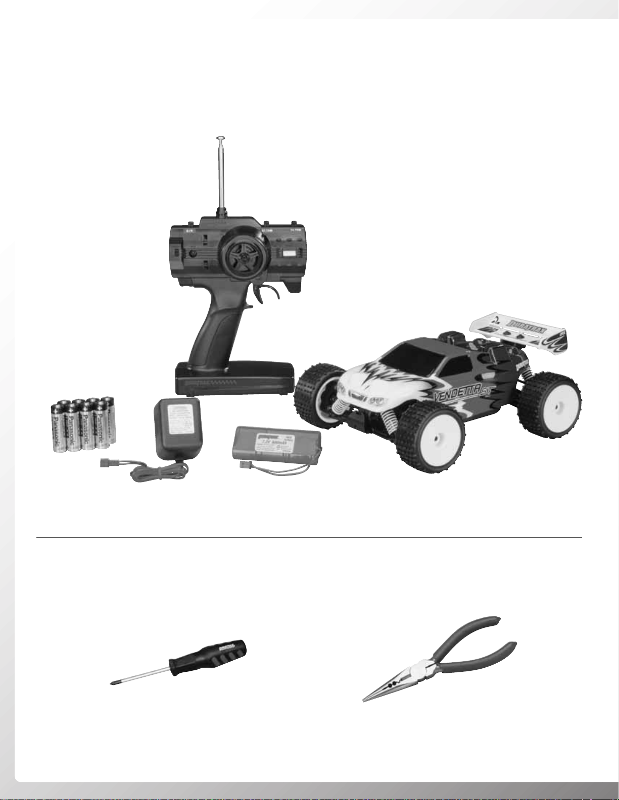
PHILLIPS HEAD SCREWDRIVER
DTXR0124
PLIERS
DTXR0300
ITEMS
ITEMS
INCLUDED
INCLUDED
The following items are included in the box.
Chassis
Body
Decal Sheet (Not Shown)
Transmitter
Transmitter Antenna
Transmitter Flag (Not Shown)
Receiver Antenna Tube with Antenna Cap (Not Shown)
Shock Spring Clips (Not Shown)
“AA” Batteries (Qty 8)
Exploded View/Parts Listing (Not Shown)
Extra Servo Saver Adapters for Hitec,JR (Not Shown)
2
Page 3

SAFETY PRECA
SAFETY PRECA
UTIONS
UTIONS
When the safety precautions are follow ed, the
Vendetta ST will provide years of enjoyment.
Use care and good sense at all times when
operating this radio controlled truggy. Failure
to use this vehicle in a safe, sensible manner
can result in injury or damage to property.You
and you alone must insure that the
instructions are carefully followed and all
safety precautions are obeyed.
• Do not use lithium polymer batteries
with the stock ESC unless a voltage cutoff unit is used.
• Do not operate the Vendetta ST near
people.Spectators should be behind the
driver or at a safe distance away from
the vehicle.
• Water can cause the electronics to short
out and can cause permanent damage.
• Always turn on the transmitter before
turning on the receiver.
• Fully extend the transmitter antenna
before operating your vehicle.
• Before turning on your radio system,
check to make sure that no one else is
running on the same frequency.
CHARGING PRECA
CHARGING PRECA
UTIONS
UTIONS
• Never leave the charger unattended
during charging.
• If the battery or the charger become hot
at any time, disconnect the battery from
the charger immediately! Failure to do
so could cause permanent damage to
the charger and battery and may cause
bodily harm.
• Do not allow water or moisture in contact
with the charger.
• Do not place the charger on or near a
flammable object during use.
• Only charge 6-cell, 2/3A-size batteries.
• Keep out of the reach of children.
• Avoid running the truggy in cold weather .
The plastic and metal parts can become
brittle at low temperatures. In addition,
grease and oil become thick, causing
premature wear and poor performance.
SPECIFICA
SPECIFICA
TION AND
TION AND
DESCRIPTION CHANGES
DESCRIPTION CHANGES
All pictures, descriptions and specifications
found in this instruction manual are subject to
change without notice.DuraTrax maintains no
responsibility for inadvertent errors in this
manual. Visit www.duratrax.com for the
latest updates and information for your model.
WWARRANTY
ARRANTY
• DuraTrax®guarantees this kit to be free
from defects in both material and
workmanship at the date of purchase.
DuraTrax will warranty this kit for 90 days
after the purchase date. DuraTrax will
repair or replace, at no charge, the
incorrectly made part.
• Make sure you save the receipt or inv oice
you were given when you bought your
model! It is your proof of purchase and
we must see it before we can honor the
warranty. Further, DuraTrax reser ves the
right to change or modify this warranty
without notice.
• In that DuraTrax has no control over the
final user assembly or material used for
final user assembly, no liability shall be
assumed nor accepted for any damage
resulting from the use by the user of the
final user-assembled product.By the act of
using the user-assembled product, the
user accepts all resulting liability.
To return your Vendetta
ST
for repairs
covered under warranty, you should send
your truggy to:
Hobby Services
3002 N. Apollo Drive Suite 1
Champaign, Illinois 61822
Attn: Service Depar tment
Phone: (217) 398-0007 9:00 am-5:00 pm
Central Time M-F
E-mail:
hobbyservices@hobbico.com
www.hobbyservices.com
If the buyer is not prepared to accept the
liability associated with the use of this
product, the buyer is advised to return
this kit immediately in new and unused
condition to the place of purchase.
STRESS-TECH
STRESS-TECH
™
™
PPARARTS
TS
GUGUARANTEE
ARANTEE
We have engineered the Vendetta ST to
take the rough and tumble abuse that mak es
R/C fun. We are so confident of the quality
and durability of the Stress-Tech plastic
parts that we will replace any Stress-Tech
plastic part you break during the first 12
months you own the truggy. Just send in the
part to us and we will send you a FREE
replacement. Please see the Vendetta ST
parts list for the items covered under the
Stress-Tech guarantee.
To receive your free replacement part
please send the following to the Hobby
Services address listed under the warranty
on the left.
❏ 1.The broken part must be included.
❏ 2.The part number and description of
the broken part.
❏ 3. Copy of your dated invoice or
purchase receipt.
❏ 4.Your name, phone number and
shipping address.
REP
REP
AIR SER
AIR SER
VICE
VICE
Repair service is available anytime.
• After the 90 day warranty, you can still
have your Vendetta ST repaired for a
small charge by the experts at DuraTrax’s
authorized repair facility, Hobby Services.
• To speed up the repair process, please
follow the instructions listed below.
❏ 1. Under most circumstances return the
ENTIRE vehicle. The exception would
be sending in a Stress-Tech par t. See
the instructions under the StressTech Guarantee.
❏ 2. Make sure the transmitter is turned off,
and all of the batteries are removed.
❏ 3. Send written instructions which include: a
list of all items returned, a THOROUGH
explanation of the problem, the service
needed and your phone number during
the day. If you expect the repair to be
covered under warranty, be sure to
include a proof of date of purchase (your
store receipt or purchase invoice).
THINGS
THINGS TTOO
KNO
KNO
W
W
3
Page 4
FINISHING
FINISHING
THE
THE
VENDETT
VENDETT
A ST
A ST
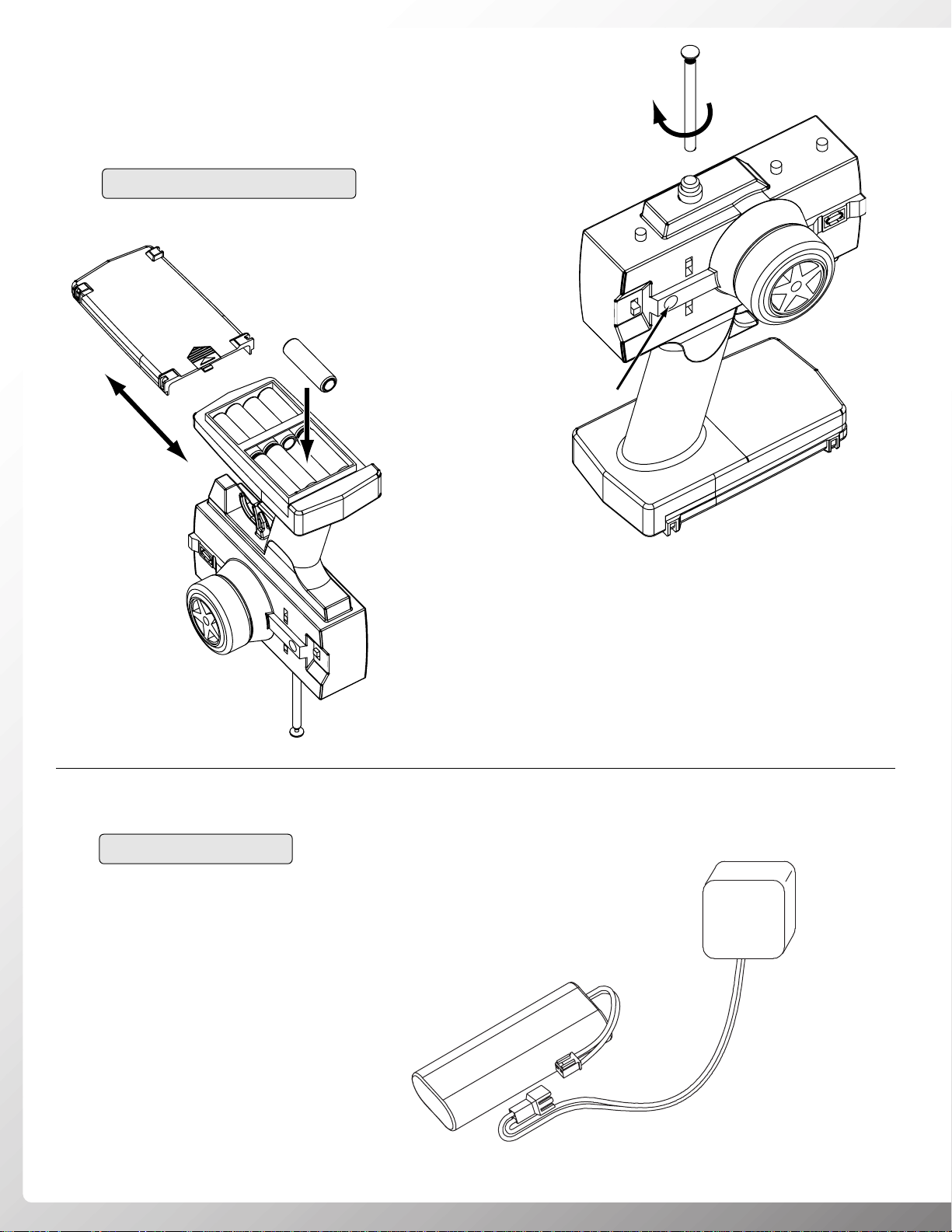
• Install eight “AA” batteries into transmitter, making sure the
polarity is correct.
• Insert the antenna into the top of the transmitter and tighten.
• Turn the transmitter on and check the battery light. If the red
light glows steady, the batteries have enough voltage. If the
red light blinks, the batteries are low and should be replaced.
4
TRANSMITTER PREPARATION
CHARGE THE BA TTER Y
• Plug in the included wall charger.
• Attach the included 6-cell (7.2V) battery to the charger.
• When the battery is fully discharged, it should take 3 hours
to fully charge. A half-charged battery, 1-1/2 hours, etc.
• CAUTION: If the battery becomes hot to the touch,
disconnect it from the charger.
–
+
+
–
–
+
–
+
+
+
–
Battery Light
3-Hour
Charger
7.2 V Battery
Page 5
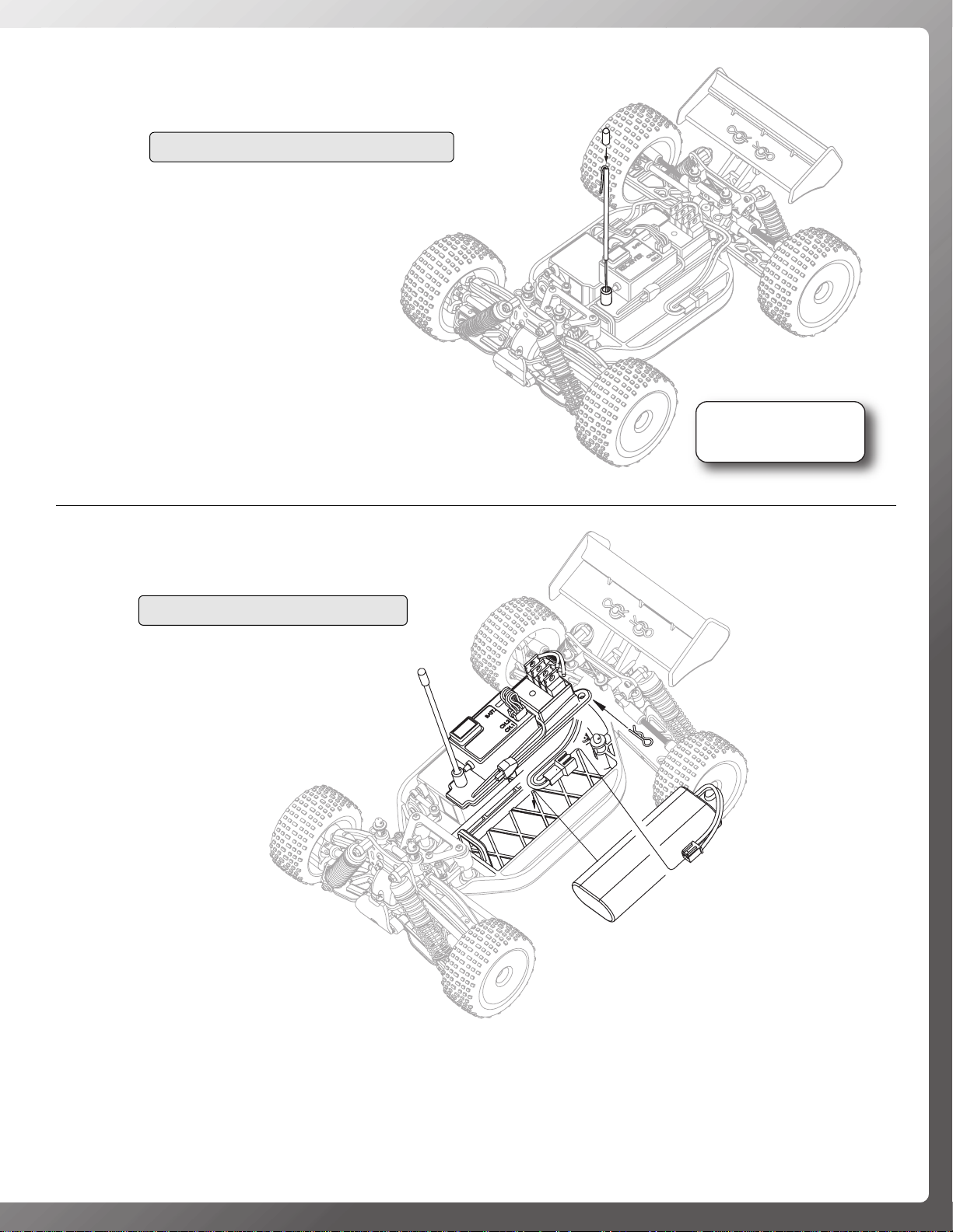
• Route the receiver antenna wire through the
receiver antenna tube.
• Insert the antenna tube into the molded
antenna mount on the battery strap.
• Install the antenna tube cap onto the top of
the antenna tube.
• DO NOT cut or coil the receiver antenna wire.
• Remove the body clip from the battery strap post.
• Remove the battery strap.
• Install the included 7.2V battery into the chassis.
• Reinstall the battery strap and secure it in place with the body clip.
• Check that the ESC is “OFF,” and then plug the battery into the ESC.
5
RECEIVER ANTENNA INSTALLATION
6-CELL BATTERY INSTALLATION
DO NOT CUT
ANTENNA WIRE!
X
7.2V Battery
Page 6
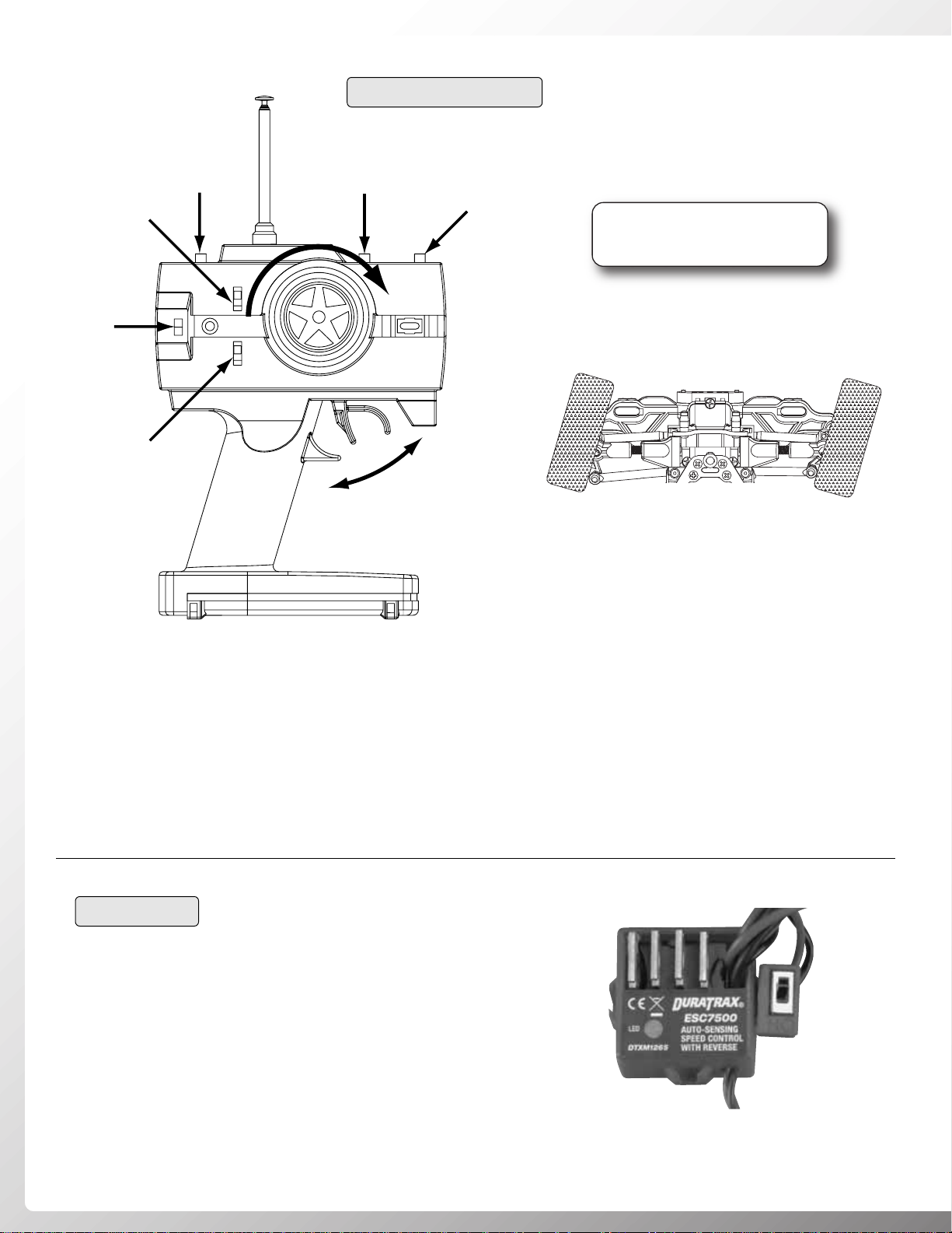
• Turn the transmitter on.Then turn the receiver on.
• Tur n the transmitter wheel to the right—the front wheels should tur n to the right. If not, move the steering
servo reverse switch.
• When running, adjust the steering trim so the truggy tracks straight.
• Gently pull back on the throttle trigger.The Vendetta ST should slowly move forward.If the truggy goes in
reverse, move the throttle reversing switch on the transmitter. The throttle trim knob may also need to be
adjusted to find neutral.
WHEELS TURN RIGHT
6
RADIO SYSTEM CHECK
• The Vendetta ST ESC is an auto-set ESC.
• You must lift the chassis off the ground during the ESC setup.
• Center the throttle trim knob on the transmitter.
• Connect the battery pack to the ESC, turn on the Tx, then the ESC.
• The LED will flash, then pull the trigger to full throttle for 2 seconds,
then go to full reverse for 2 seconds.
• The ESC is now set up.
• You must set the ESC every time you change the battery.
ESC SETUP
Steering
Servo
Reverse
Switch
On/Off
Throttle
Servo
Reverse
Switch
Steering
Dual
Rate
Steering
Trim
Forward
Throttle
Trim
Reverse
CHECK THE RADIO SYSTEM
FOR PROPER FUNCTION
!
BEFORE EACH RUN
Page 7
BEFORE EACH RUN
• IMPORTANT: Check to make sure that
all screws are tight. Always use
threadlock (DTXR2010) on screws
going into metal.
• Before running always check the condition of your radio
system batteries and replace/recharge if necessary.
• Check to make sure that all of the moving parts of the
Vendetta ST move freely and do not bind.
• Before running, turn on the radio and make sure the
servos move easily and in the proper direction.
• Check for broken or damaged parts.Replace any broken or
damaged parts before running the Vendetta ST .Running of
the Vendetta ST with broken or damaged parts could result
in damage to other parts.
• Check to make sure that all wires are properly connected.
• Check that the ESC and receiver are properly secured to
the chassis.
AFTER EACH RUN
• Clean any large globs of dirt or debris from the chassis
and moving parts.
• Check for any broken or damaged parts. This way parts
may be replaced before the next run.
• Disconnect and remove the battery from the chassis.
AFTER EVERY 10 RUNS
• Check to make sure that the bearings are free of dirt and
debris, and roll smoothly.
• Check the shocks for oil leakage. Inspect the shaft and
O-rings for wear and damage. Replace if necessary. (A
shock shaft with scratches you can feel with a fingernail
should be replaced.)
• Check the tires to make sure they are still properly glued
to the wheels.
MAINTENANCE
MAINTENANCE
TIPS
TIPS
7
• Decal the body to your liking. Use the
photos on the box as a reference.
• Install the body onto the chassis using
two body clips.
BODY INSTALLATION
Page 8
When tuning the Vendetta ST make sure that you have
equal lengths from one side to the other on the shocks and
upper rods. Also, make sure to have the shock pre-load
adjusters at the same setting from left to right. They do not
have to be the same front to rear.
RIDE HEIGHT ADJUSTMENT
The ride height of the Vendetta ST is easily adjusted by using
the included pre-load spacers.To increase the ride height of
the Vendetta ST, install a pre-load spacer onto each of the
shock bodies between the spring and the shock cap. The
more pre-load clips you install, the more ride height you will
achieve. Make sure you install the same amount of pre-load
clips from side to side. To lower the ride height of the
V endetta ST, remove the desired amount of pre-load spacers
from the shocks. TIP: Rough, rocky surfaces require higher
ride height; flat, smooth surfaces allow a lower ride height.
FRONT SHOCK ADJUSTMENT
Moving the tops of the shocks out will increase steering,
resulting in quicker reaction. Moving the tops of the shocks
in will result in slower steering reaction, but will be smoother
over bumps. Mounting the bottoms of the shocks in the
inside hole will give more slow-speed steering but will take
away some high-speed steering.
REAR SHOCK ADJUSTMENT
Moving the tops of the shocks in will result in more traction
in the corners and smoother handling over bumps. Moving
the tops of the shocks out will give the truggy more steering
and better ability to handle the large jumps.
SHOCK SPRINGS
DuraTrax offers two different optional shock springs: Heavy
(green) and Extra Firm (blue), the Vendetta ST comes stock
with Medium springs (yellow). For rutted tracks with small
jumps, a soft spring should be used. For tracks with large
jumps, a heavy spring should be used to help prevent
chassis slap.
SHOCK OIL
The Vendetta ST comes stock with 25 weight oil in the
shocks.The handling of the truggy can be tuned by changing
the shock oil to either heavier (bigger number) or lighter
(lower number.) By putting heavier oil in the shocks, the
truggy will have less chassis roll and become less responsive .
Putting lighter oil in the shocks will cause the truggy to be
more responsive and hav e more chassis roll.For smooth, flat
surfaces, a thicker oil would be best. For surfaces that are
rough or have jumps, a lighter oil would be best.
PINIONS
The Vendetta ST comes stock with the 13 tooth pinion. To
obtain higher top speeds you can install a larger pinion gear
onto the motor.This will, however, decrease your acceleration
and run time. TIP: Smaller pinion equals more torque, less
top speed. Larger pinion equals more top speed, less torque.
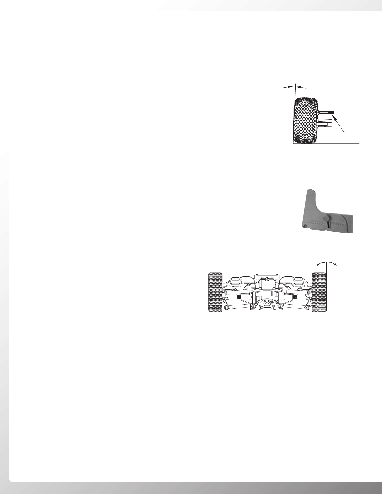
CAMBER
Camber refers to the angle
at which the tire and wheel
ride in relation to the
ground when viewed from
the front or rear. Negative
camber is when the wheels
lean inward and positive
camber is when the wheels
lean outward. Usually
adding a small amount of negative camber (0° to -2°) will
increase traction. However, adding too much camber will
decrease traction. The objective is to keep as much of the
tire as possible in contact with the running surface. Never
put in positive camber. Make sure that both sides are equal.
Use the DuraTrax Pit Tech™Camber
Gauge (DTXR1145) to accurately set
up your Vendetta ST.
TOE-IN AND TOE-OUT
Toe-in is when the fronts of the tires point towards each other.
Toe-out is when the fronts of the tires point away from each
other. Toe-in increases stability dur ing acceleration and high
speed.Howe v er , toe-in also decreases steering when entering
a corner. Toe-out will increase steering into corners, but will
decrease the overall stability during acceleration. The front
typically is set-up with 0° to -2° of toe-in.For adjustable toe-in,
install the optional steering turnbuckle set (DTXC9592).
CASTER
The Vendetta ST has adjustable caster. Caster refers to the
angle of suspension vertically. By placing the adjuster clip
behind the fron upper arm, you decrease caster angle. This
will give more initial turn-in but decrease on power steering
and straight line stability.
Placing the adjuster clip in front of the front upper arm
increases the caster.This will increase on power steering and
straight line stability, but reduce initial turn-in.
t
TUNING
TUNING
GUIDE
GUIDE
8
2° Negative Camber
Adjust
Toe-In
Toe-Ou
Page 9
9
MAINTENANCE
MAINTENANCE
GUIDE
GUIDE
The following section is provided to help you with
maintenance and repairs to your Vendetta ST. Pay extra
attention to the notes and tips for proper assembly.
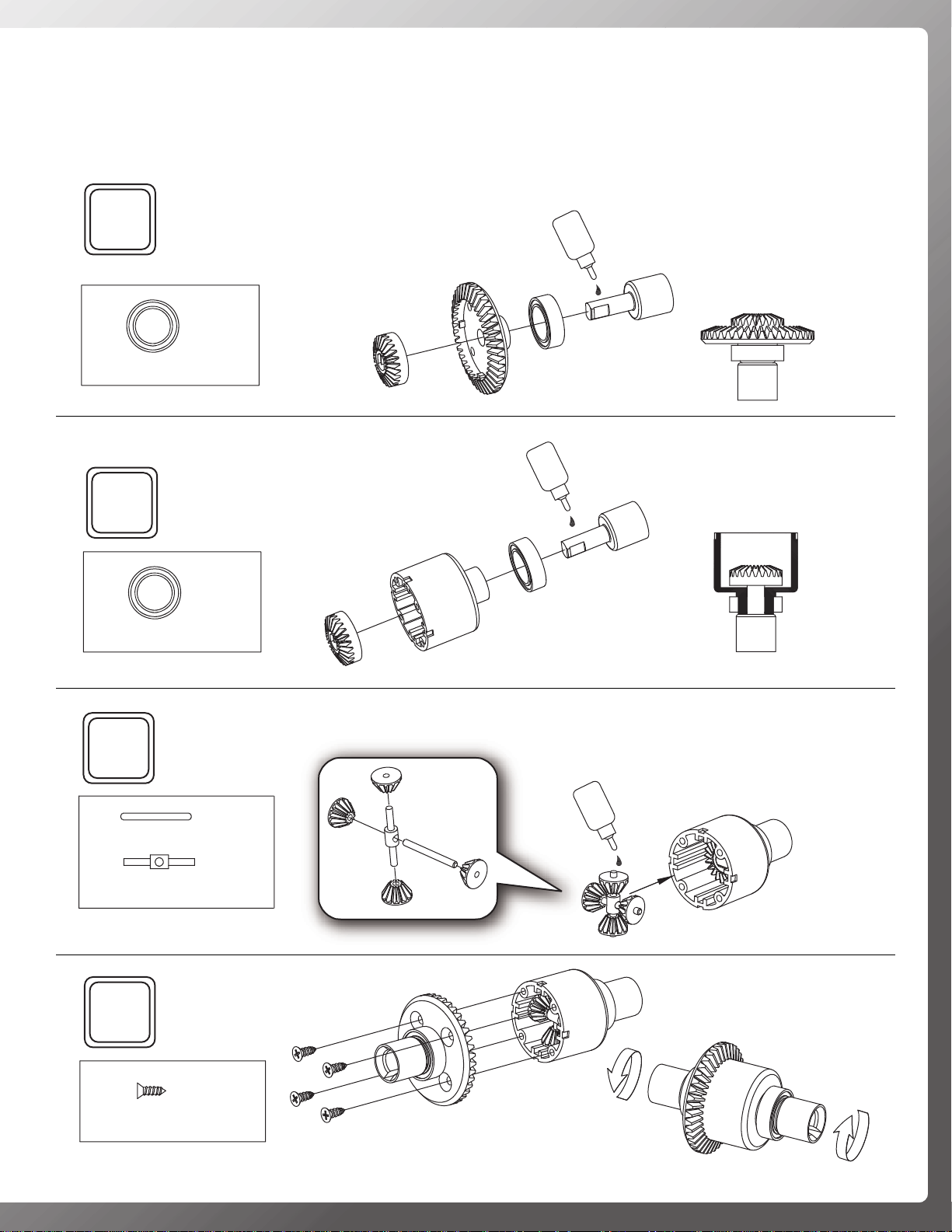
Gear Differential
1
8x12mm Ball Bearing
For Front and Rear
...2
2
Oil
x2
Oil
...2
8x12mm Ball Bearing
3
...2
Differential Cross Pin A
...2
Differential Cross Pin B
4
x2
Oil
x2
...8
2x6mm F/H S/T Screw
x2
Page 10

10
55
6
Oil
Oil
Oil
6x10mm Ball Bearing
8x12mm Ball Bearing
3mm E-Clip
3mm E-Clip
8x12mm
8x12mm
6x10mm
2x8mm Drive Shaft Pin
...2
...1
...1
...1
Page 11

11
7
...5
2.6x8mm S/T Screw
8
...2
2.6x6mm Screw
9
When using optional pinion gear set,
adjust motor position.
13T 19T 11T 16T 21T
4.7mm
...1
3x3mm Set Screw
...1
13T Pinion
Page 12

12
10
...2
2.6x6mm Motor
Mount Screw
11
2.6x8mm S/T Screw
2.6x12mm S/T Screw
2.6x12mm
...2
...2
12
...1
2.6x10mm F/H S/T Screw
2.6x8mm
...2
2.6x8mm F/H Screw
Page 13

13
13 14
15
...2
1.5 mm E-Clip
16
...2
2.6x6 mm Screw
2.6x6 mm
17
...4
2.6x6 mm Screw
Page 14

14
18
19
2x6 mm S/T Screw
...4
2.6x8mm S/T Screw
2.6x8mm
Flange Locknut
2.6x8mm S/T Screw
2.6x8mm
...4
2.6x10mm F/H S/T Screw
...2
...2
...2
...2
20
Page 15

15
21
...3
2.6x8mm S/T Screw
...1
2.6x12mm S/T Screw
22
6x10mm Ball Bearing
...2
2.6x12mm
2.6x8mm
...2
23
6x10mm Ball Bearing
Left Right
Page 16

16
24
25
Right
Left
x4
26
2x8mm Shaft Pin
A
B
A
B
A=B A=B
R
L
Pivot ball stud end should
cover half the hole in the
upper arm.
Pivot ball stud end should
cover half the hole in the
upper arm.
Page 17

17
27
28
29
2x26.5mm Shaft
2x37.5mm Shaft
Left
Right
...1
2.6x10mm
F/H S/T Screw
...2
2x6mm S/T Screw
Page 18

18
30
3x30mm Threaded
Shaft
25.5–26mm
x2
31
32
...1
2x12mm Screw
...2
6x10mm Ball Bearing
21–21.5mm
x2
2x26.5mm Shaft
3.8mm Pivot Ball
Left
1.5mm1.5mm
Page 19

19
33
...1
2x12mm Screw
...2
6x10mm Ball Bearing
2x26.5mm Shaft
Rear Hinge Pin
Pivot Ball
Right
34
2x37.5mm Shaft
1.5mm 1.5mm
Right
Left
Page 20

35
20
...3
2.6x10mm
F/H S/T Screw
...4
2x6mm
S/T Screw
2x6mm S/T
36
1.5 mm E-Clip
Front & Rear Shocks
O-Ring
2.6x10mm F/H S/T
x4
...8
...8
O-Ring
Oil
Apply a small amount of oil
to the shock shaft before
inserting into the shock assembly.
This will help prevent the shock
shaft from tearing the O-rings.
Page 21

37
21
38
...4
...4
Completely fill the shock
body with shock oil. Slowly
work the piston up and
down to remove air bubbles.
Do not push the piston out
of the shock oil. Slowly
tighten the shock cap onto
the shock body to allow the
remaining air bubbles
to escape.
39
Oil
...2
2x14mm Cap Screw
...2
2x12mm Screw
Front Shocks
Page 22

40
22
Rear Shocks
Adjust the ride height using
the shock spring clip.
...2
2x12mm Screw
...2
2x14mm Cap Screw
41
...2
The body posts
will need to be
trimmed to mount
most bodies.
Page 23

42
23
43
2.6x8mm
...2
The body posts
will need to be
trimmed to mount
most bodies.
Page 24

44
24
45
3x12mm Screw
2.6x12mm Screw
OR
For standard size servos, the
mounting tabs will have to be
trimmed off to fit in the chassis.
FJH
Use a sharp hobby knife or a
pair of Lexan scissors. Be
careful not to damage the
servo case.
2.6x8mm
Page 25

46
25
Double-Sided
Tape
Thoroughly clean the chassis and servo case
with alcohol before applying the servo tape.
47
Standard
Servo
Micro
Servo
Page 26

26
48
49
50
Double-Sided
Tape
Speed Control
CH2
Thoroughly clean the battery strap, receiver and
the ESC with alcohol before applying the servo tape.
Page 27

27
51
...1
Steering Servo
CH1
Yellow
to motor
Red
52
53
54
CA
Glue
x4
x4
x4
55
...4
2.6x10mm F/H S/T Screw
CA
Glue
Page 28

Copyright © 2006 V1.0
DTXZ1091 for DTXD14**
Other Accessories Available From DuraTrax
1/18th Micro Vehicle
Carry Bag
DTXP2028
Pit Tech™Mini Car Stand
DTXC2361, DTXC2362
DTXC2363, DTXC2364
TX NiCad Conversion Kit
(For use with DuraTrax & Futaba Systems)
DTXP4010
6-cell NIMH Battery
DTXC2195
Ultimate Driver Set
DTXR0183
AC/DC Piranha™Digital Charger
DTXP4005
Pit Tech™ Camber Gauge
DTXR1145
Long Nose Pliers
DTXR0300
For more optional parts and accessories, contact your hobby dealer or
www.duratrax.com
Graphite Hop-Ups Available for the Vendetta ST
Graphite Battery Strap
DTXC6311
Graphite Front Brace
DTXC6599
Graphite Chassis
DTXC6996
Graphite Diff Cover
DTXC7442
Graphite Diff Case
DTXC7443
Graphite Center Driveshaft
DTXC7482
Graphite Steering Drag Link
DTXC7489
Graphite Rear Hub
DTXC8006
Graphite Steering
Servo Hold-Down
DTXC8813
Power Shot
Motor Cleaner 12oz
DTXC2459
 Loading...