

Page 1
®
ASSEMBLY AND OPERATION MANUAL
duratrax.com
™
Page 2
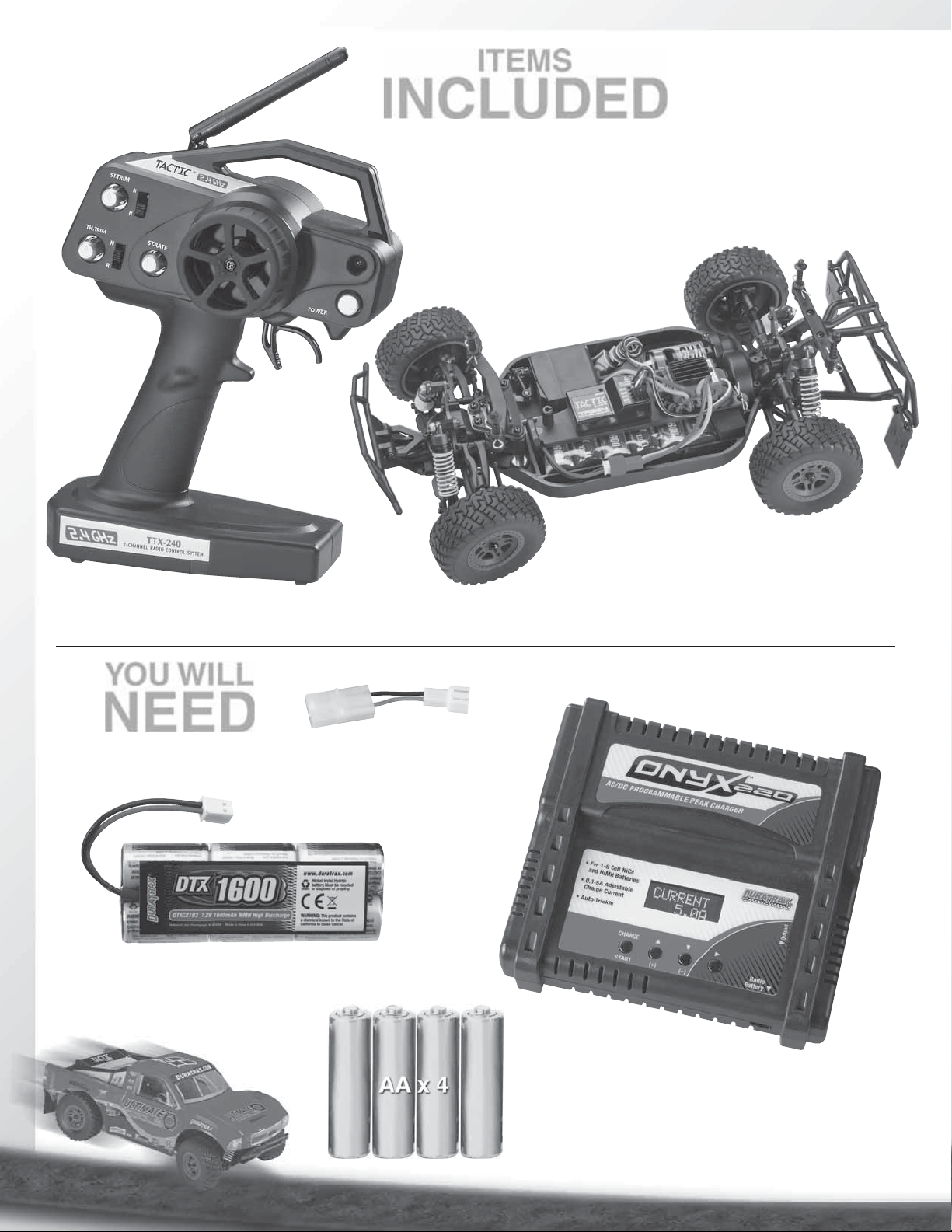
ITEMS
INCLUDED
The following items are included with your Vendetta SC.
YOU WILL
Chassis
Body
Instruction Manual
Exploded View/Parts Listing
Transmitter
Decal Sheet
NEED
BATTERY ADAPTER
6-CELL 1600 MAH NIMH BATTERY
DTXC2193
(FOR CHARGING)
DTXC2210
ONYX™ 220 PROGRAMMABLE
PEAK CHARGER
DTXP4220
2
Page 3

THINGS TO
SPECIFICATION AND
DESCRIPTION CHANGES
STRESS-TECH™ PART S
GUARANTEE
KNOW
SAFETY PRECAUTIONS
When these safety precautions are
followed, the Vendetta SC will provide
years of enjoyment. Use care and good
sense at all times when operating this radio
controlled truck. Failure to use this vehicle
in a safe, sensible manner can result in
injury or damage to property. You and you
alone must ensure that the instructions are
carefully followed and all safety precautions
are obeyed.
• Do not operate the Vendetta SC near
people. Spectators should be behind the
driver or at a safe distance away from
the vehicle.
• Make sure to read the instructions included
with the battery and charger before
charging the battery.
• Do not leave any charger unattended during
charging. If the battery or charger become
hot at any time, disconnect the battery
from the charger immediately! Failure to
do so may cause permanent damage to
the charger and battery and may cause
bodily harm or property damage.
• Do not cover the air intake holes on the
charger during charging. This may cause
the charger to overheat.
• Do not allow the electronic speed control
(ESC) or other radio equipment to come
into contact with moisture. Water can
cause electronics to short out and can
cause permanent damage.
• Always turn on the transmitter before
turning on the electronic speed control.
• Always turn off the ESC before turning off
the transmitter.
• Allow the motor and ESC to cool before
each run.
HELPFUL HINTS
• Avoid working over a deep pile carpet. If
you drop a small part or screw, it may be
diffi cult to fi nd.
• Place a mat or towel over your work area.
This will prevent parts from rolling off and
protect the work surface.
• Avoid running the truck in cold weather. The
plastic and metal parts can become brittle
at low temperatures. In addition, grease
and oil become thick, causing premature
wear and poor performance.
• Test fi t all parts before attaching
them permanently.
All pictures, descriptions and specifi cations
found in this instruction manual are subject
to change without notice. DuraTrax maintains
no responsibility for inadvertent errors in this
manual. Visit duratrax.com for the latest
updates and information for your model.
WARRANTY
• DuraTrax® guarantees this kit to be free from
defects in both material and workmanship at
the date of purchase. DuraTrax will warranty
this kit for 90 days after the purchase
date. DuraTrax will repair or replace, at no
charge, the incorrectly made part.
• Make sure you save the receipt or invoice
you were given when you bought your
model! It is your proof of purchase and
we must see it before we can honor the
warranty. Further, DuraTrax reserves the
right to change or modify this warranty
without notice.
• In that DuraTrax has no control over the
fi nal user assembly or material used for
fi nal user assembly, no liability shall be
assumed nor accepted for any damage
resulting from the use by the user of the
fi nal user-assembled product. By the act
of using the user-assembled product, the
user accepts all resulting liability.
To return your Vendetta SC for repairs
covered under warranty, you should send
your truck to:
Hobby Services
3002 N. Apollo Drive Suite 1
Champaign, Illinois 61822
Attn: Service Department
Phone: (217) 398-0007
9:00 am–5:00 pm Central Time M-F
E-mail: hobbyservices@hobbico.com
hobbyservices.com
If you are not prepared to accept the
liability associated with the use of this
product, you are advised to return this
kit immediately in new and unused
condition to the place of purchase.
3
We have engineered the Vendetta SC to
take the rough and tumble abuse that makes
R/C fun. We are so confi dent of the quality
and durability of the Stress-Tech plastic
parts that we will replace any Stress-Tech
plastic part you break during the fi rst 12
months you own the truck. Just send in the
part to us and we will send you a FREE
replacement. Please see the parts list for
the items covered under the Stress-Tech
guarantee.
To receive your free replacement part
please send the following to the Hobby
Services address listed under the warranty
on the left.
❏ 1. The broken part must be included.
❏ 2. The part number and description of the
broken part.
❏ 3. Copy of the dated invoice or
purchase receipt.
❏ 4. Your name, phone number and
shipping address.
REPAIR SERVICE
Repair service is available anytime.
• After the 90 day warranty, you can still
have your Vendetta SC repaired for a
small charge by the experts at DuraTrax’s
authorized repair facility, Hobby Services.
• To speed up the repair process, please
follow the instructions listed below.
❏ 1. Under most circumstances return
the ENTIRE vehicle. The exception would
be sending in a Stress-Tech part. See the
instruction under the Stress-Tech Guarantee.
❏ 2. Make sure the transmitter is turned off,
and all of the batteries are removed.
❏ 3. Send written instructions which include:
a list of all items returned, a THOROUGH
explanation of the problem, the service
needed and your phone number during the
day. If you expect the repair to be covered
under warranty, be sure to include a proof
of date of purchase (your store receipt or
purchase invoice).
Page 4
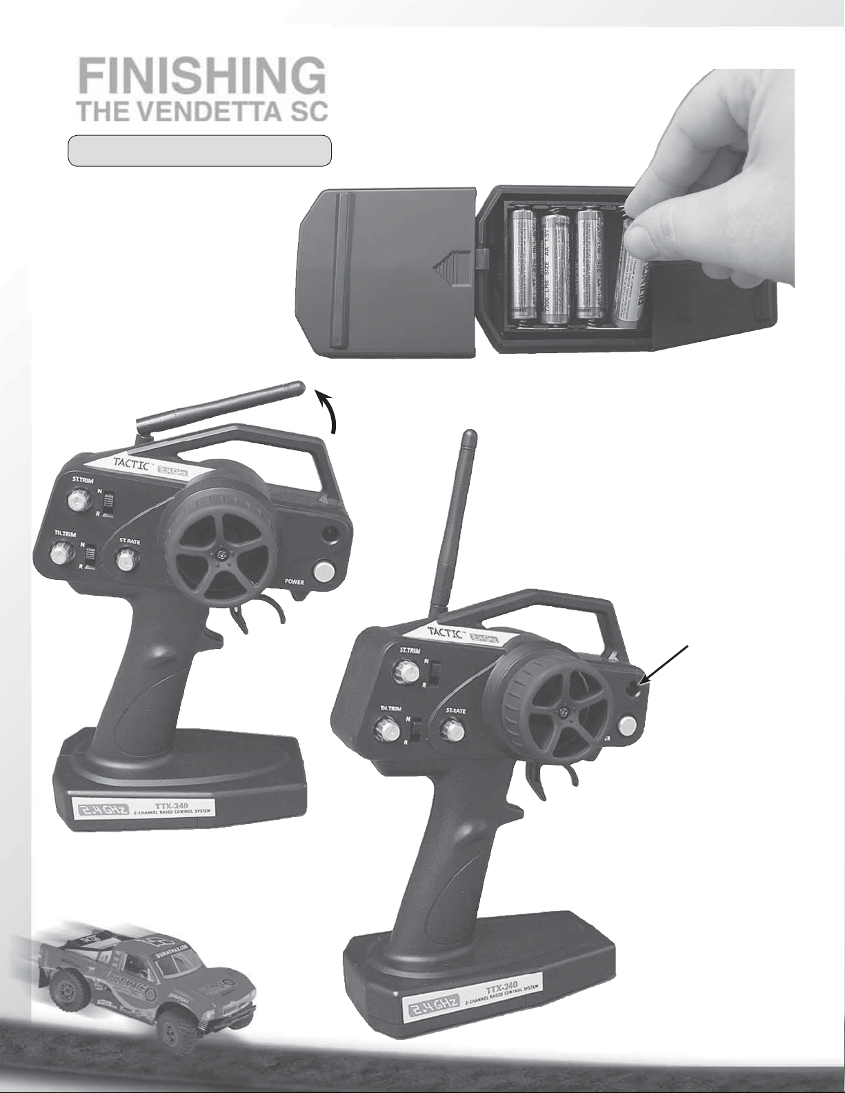
FINISHING
THE VENDETTA SC
TRANSMITTER PREPARATION
• Slide off the batttery tray door
and install four “AA” batteries.
Make sure the polarity is
correct.
• Raise the antenna at the top of
the transmitter.
RED BATTERY
LIGHT
• Turn on the transmitter and check
the battery light. If the red light
glows steadily, the batteries have
enough voltage. If the red light
blinks, the batteries are low and
should be replaced.
4
Page 5
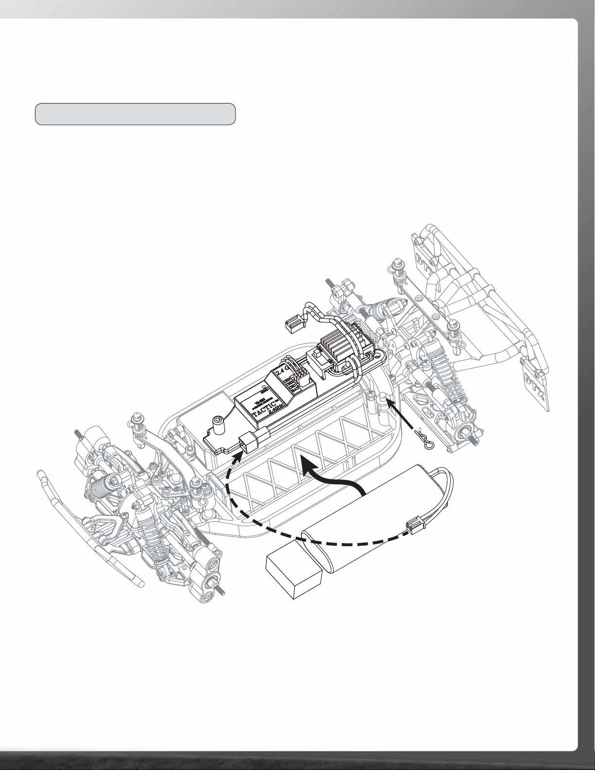
6-CELL BATTERY INSTALLATION
• Remove the body clip from the battery strap post.
• Remove the battery strap and foam spacer.
• Install a fully charged 7.2V battery into the chassis.
• Reinstall the battery strap and foam spacer. Secure
them in place with the body clip.
• Make sure the ESC is turned “OFF” before plugging
the red battery connector into the red ESC connector.
Foam
Spacer
5
7.2V Battery
Page 6
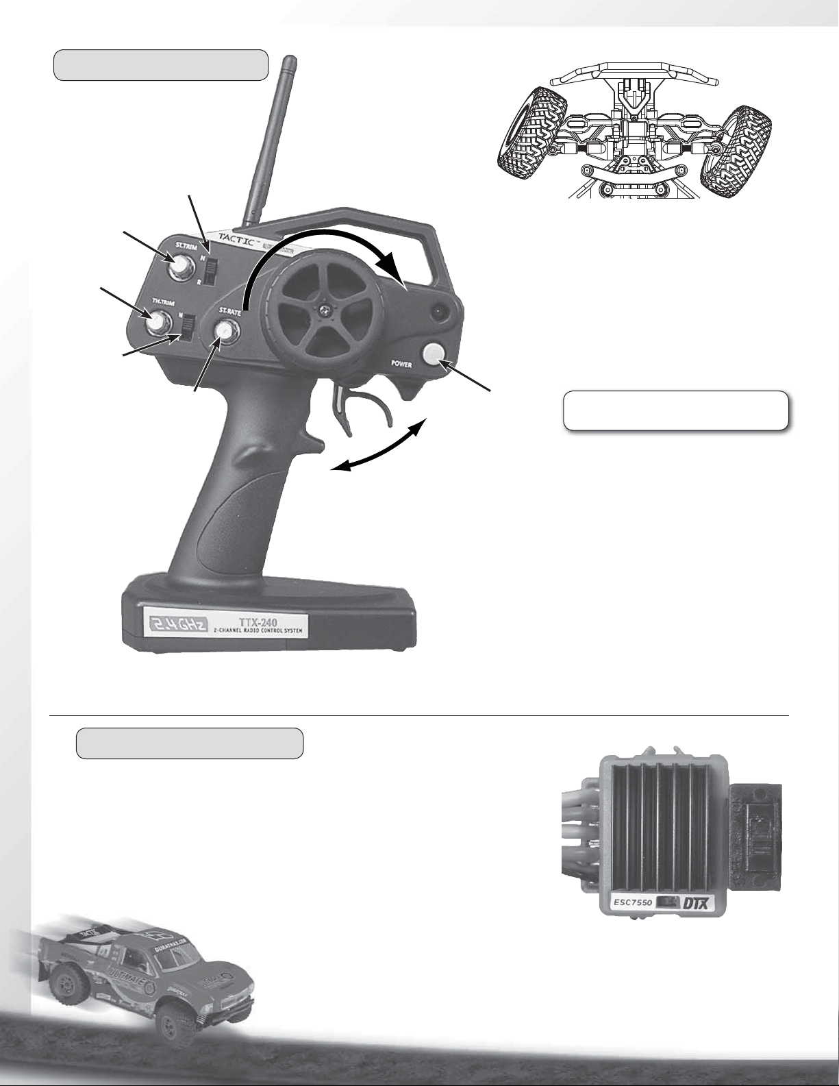
RADIO SYSTEM CHECK
Steering
Reversing
Switch
Steering
Tr i m
Throttle
Tr i m
Throttle
Reversing
Switch
Steering
Rate
Forward
• Raise the antenna.
• Turn on the transmitter before turning on the ESC.
• Turn the transmitter wheel to the right—the front
wheels should turn to the right. If not, move the
steering servo reverse switch.
• When running, adjust the steering trim so the truck
tracks straight.
On/Off
Reverse
• Slowly pull on the throttle trigger. The Vendetta SC should
slowly move forward. If the truck goes in reverse, move the
throttle reversing switch on the transmitter. The throttle trim
knob may also need to be adjusted to find neutral.
• The receiver should be factory bound to the transmitter.
However, if you ever need to bind, follow these steps:
1. Turn on the transmitter.
2. Turn on the receiver via the switch on the ESC. If the
receiver is not bound, the LED light will not be on.
3. Push and hold the bind button on the receiver until the
light glows red.
4. Release the bind button.
5. If the binding is successful, the LED will flash once and
then remain ON.
ALWAYS CHECK THE RADIO
!
OPERATION BEFORE EACH RUN
SPEED CONTROL SET UP
NOTE: If you do not wish to change the ESC settings, simply wait for the red light
to stop flashing (about two seconds) before moving the throttle trigger.
1. Center the throttle trim adjustment and turn on the transmitter.
2. Move the switch on the ESC to the “OFF” position and connect the battery.
3. Lift the chassis so its wheels are off the ground.
4. Turn on the ESC. It will “beep” once and the red light will begin to flash indicating
the ESC is in set-up mode.
5. Program the ESC by moving the trigger to
the full speed position, then to the full brake
position. Return the trigger to the neutral position.
The ESC will beep four times and the green light will come on,
indicating the ESC has been set up.
6
Page 7
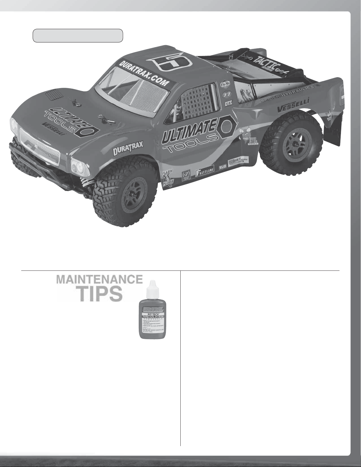
BODY INSTALLATION
• Decal the body to your liking. Use the
photos on the box as a reference.
MAINTENANCE
TIPS
BEFORE EACH RUN
• IMPORTANT: Check to make sure
that all screws are tight. Always use
threadlock (DTXR2010) on screws
threading into metal.
• Check the condition of your radio system batteries and
replace/recharge if necessary.
• Make sure that all of the moving parts of the Vendetta SC
move freely and do not bind.
• Turn on the radio and make sure the servo moves easily
and in the proper direction.
• Check for any broken or damaged parts. Replace them before
running the Vendetta SC. Running the Vendetta SC with
broken or damaged parts could damage additional parts.
• Install the body onto the chassis using
four body clips.
AFTER EACH RUN
• Clean any debris from the chassis and moving parts.
• Check for any broken or damaged parts. Replace them
before the next run.
• Disconnect and remove the battery from the chassis.
• Allow the motor and ESC to cool.
AFTER EVERY 10 RUNS
• Make sure that the bearings are free of dirt and debris, and
roll smoothly.
• Check the shocks for oil leakage. Inspect the shafts and
O-rings for wear and damage. Replace if necessary. IF a
shock shaft has scratches you can feel with a fingernail, it
should be replaced.
• Make sure the tires are still securely glued to the rims.
• Make sure that all wires are properly connected.
• Make sure the ESC, servo and receiver are properly secured.
7
Page 8
TUNING
GUIDE
When tuning the Vendetta SC make sure that you have equal
lengths from one side to the other on the shocks, upper rods,
and front pivot ball knuckles. Also, make sure to have the
shock pre-load adjusters at the same setting from left to
right. They do not have to be the same front to rear.
RIDE HEIGHT ADJUSTMENT
The ride height of the Vendetta SC is easily adjusted by
using the clip-on pre-load collars. To increase the ride height
of the Vendetta SC, add more pre-load collars between the
shock cap and the upper shock collar. Make sure you have
the same pre-load from side to side. To lower the ride height,
remove the pre-load collars. TIP: Rough, bumpy surfaces
require higher ride height; fl at, smooth, or high traction
surfaces allow a lower ride height.
PINIONS
The Vendetta SC comes stock with the 12 tooth pinion. To
obtain higher top speeds you can install a larger pinion gear
onto the motor. This will, however, decrease your acceleration
and run time. TIP: Smaller pinion equals more torque, less
top speed. Larger pinion equals more top speed, less torque.
If you use a larger pinion, it is recommended that you either
solder your motor wires directly to the ESC or use a hichcurrent motor connector.
WHEELBASE
SHOCK SPRINGS
The Vendetta SC comes stock with medium springs (yellow,
DTXC8952). For low traction or bumpy tracks, use a soft
spring (White, DTXC8953). For high traction or smooth tracks,
use a fi rm spring (Green, DTXC8954).
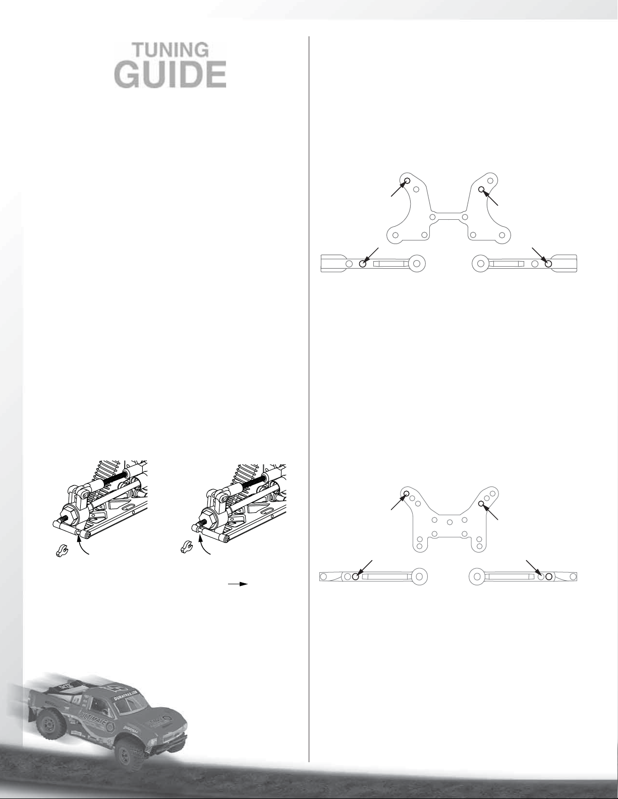
FRONT SHOCK ADJUSTMENT
Top Shock, Outer Position:
More Steering
Faster Suspension Reaction
Inner Mount Position:
More Slow-Speed Steering
FRONT
Top Shock, Inner Position:
Slower Steering
Smoother Over Bumps
Outer Mount Position:
More High-Speed Steering
Moving the tops of the shocks to the outer position will
increase steering reaction but decrease front traction.
Moving the tops of the shocks in will result in slower steering
reaction but will be smoother over bumps and have more
front traction. Mounting the bottom of the shocks in the inside
hole will give more front traction but slower steering reaction.
Mounting the bottom of the shocks in the outer position will
give less front traction but increase steering reaction. The
lower mounting points are for major adjustments and the top
mounting points are for minor adjustments.
REAR HUB
LONG
SPACER
IN FRONT
SHORT
SPACER
IN REAR
FRONT OF VEHICLE
You can adjust the wheelbase on the Vendetta SC by placing
the adjuster clips in front of or behind the rear hub carrier. A
shorter wheelbase will provide more steering, while a longer
wheelbase will be more stable.
REAR SHOCK ADJUSTMENT
Top Shock, Outer Position:
More Steering,
Less Rear Traction
Inner Mount Position:
Less Steering,
Smoother Over Bumps
REAR
Top Shock, Inner Position:
More Rear Grip
More Rear Traction
Outer Mount Position:
More Steering,
Less Control Over Bumps
Moving the tops of the shocks out will increase steering
reaction and decrease rear traction. Moving the tops of the
shocks in will result in slower steering reaction but will be
smoother over bumps and have more rear traction. Mounting
the bottom of the shocks in the inside hole will give more
rear traction. Mounting the bottom of the shocks in the
outside hole will give less rear traction and increase steering
reaction. The more angled the rear shock is, the more side
grip. The more vertical the rear shock is, the less side grip.
The lower mounting points are for major adjustments and
the top mounting points are for minor adjustments.
8
Page 9

SHOCK OIL
The Vendetta SC comes with 30-weight oil in the shocks. The
handling of the truck can be tuned by changing the shock oil
to either heavier (bigger number) or lighter (smaller number).
By putting heavier oil in the shocks, the truck will have less
chassis roll and become more responsive. Putting lighter oil
in the shocks will cause the truck to be less responsive and
have more chassis roll. For smooth, high-traction surfaces, a
thicker oil would be best. For low-traction or bumpy surfaces,
a lighter oil would be best.
CAMBER
2˚ NEGATIVE CAMBER
ADJUST LENGTH
TO CHANGE
THE CAMBER
FRONT TRACK WIDTH
The Vendetta SC has adjustable front track width due to its
pivot ball knuckle design. To decrease track width, screw in
the upper and lower pivot balls equally. To increase track
width, screw out the upper and lower pivot balls equally. Make
sure that both sides are the same distance from the end of
the upper and lower arms. You can check this by measuring
from the end of the upper and lower arm to the outside of the
knuckle. Track width affects the truck’s handling and steering
response. Wider front track width decreases steering reaction
and front grip. Narrow front track width increases steering
reaction and front grip.
TOE-IN AND TOE-OUT
TOE-IN
Camber refers to the angle at which the tire and wheel
ride in relation to the ground when viewed from the front or
rear. Negative camber is when the wheels lean inward and
positive camber is when the wheels lean outward. Usually
adding a small amount of negative camber (0° to -2°) will
increase traction. However, adding too much camber will
decrease traction. The objective is to keep as much of the
tire as possible in contact with the running surface. Never put
in positive camber. Make sure that both sides are equal.
Use the DuraTrax Pit Tech™ Camber Gauge
(DTXR1145) to accurately set up your
Vendetta SC.
CASTER
The Vendetta SC has adjustable caster. Caster refers to the
fore/aft angle of suspension. By placing the adjuster clips
behind the front upper arm, you decrease caster angle. This
will give more initial turn-in but decrease on-power steering
and straight-line stability.
TOE-OUT
Toe-in is when the fronts of the tires point towards each other.
Toe-out is when the fronts of the tires point away from each
other. Toe-in increases stability during acceleration and high
speed. However, toe-in also decreases steering when entering
a corner. Toe-out will increase steering into corners, but will
decrease the overall stability during acceleration. The front
typically is set up with 0° to 1° of toe-in.
Placing the adjuster clips in front of the front upper arm
increases the caster. This will increase on-power steering and
straight-line stability, but reduce initial turn-in.
9
Page 10

MAINTENANCE
GUIDE
The following section is provided to help you with maintenance
and repairs to your Vendetta SC.
1
8x12mm Ball Bearing
2
..........2
8x12mm Ball Bearing
3
..........2
Oil
x2
Oil
x2
Oil
..........2
1.5x16mm Pin
..........2
1.5x16mm Shaft
..........8
2x6mm F/H S/T Screw
4
6x10mm
8x12mm
x2
..........1
2x8mm Pin
..........1
6x10mm Ball Bearing
8x12mm
..........1
3mm E-Clip
..........2
8x12mm Ball Bearing
10
Page 11

5
6
2.6x12mm
S/T Screw
2.6x8mm
S/T Screw
..........1
2.6x12mm S/T Screw
..........4
2.6x8mm S/T Screw
7
2.6x6mm Screw
..........2
8
4.5mm
..........1
3x3mm Set Screw
11
Page 12

9
..........2
2.6x6mm Screw
10
2.6x12mm
S/T Screw
..........2
2.6x8mm S/T Screw
..........2
2.6x12mm S/T Screw
11
..........1
2.6x10mm
F/H S/T Screw
..........2
2.6x8mm
S/T Screw
2.6x8mm F/H Screw
2.6x10mm
F/H S/T Screw
2.6x8mm
F/H Screw
12
Page 13

12
..........3
3.8mm Ball Stud
..........2
13 14
39mm
3x25mm
Threaded Shaft
2x6mm S/T Screw
x2
..........2
15 16
..........2
2.6x6mm Screw
.........2
17 18
Body Clip
Use bottom
hole
2.6x8mm Screw
2x16mm Socket
Head Cap Screw
..........4
..........2
13
Page 14

19
..........4
2.6x8mm S/T Screw
..........2
2.6x10mm F/H S/T Screw
20
2.6x8mm
S/T Screw
2.6x10mm
F/H S/T Screw
Use bottom
hole
21
..........2
2x16mm Socket
Head Cap Screw
22
..........2
2.6x8mm
S/T Screw
.........2
Body Clip
..........2
2mm Lock Nut
..........2
2.6x8mm S/T Screw
..........2
3.8mm Ball Stud
14
Page 15

23
..........3
2.6x8mm S/T Screw
..........1
2.6x12mm S/T Screw
24
2.6x12mm
S/T Screw
2.6x8mm
S/T Screw
....4
Pivot Ball Retainer
.....2
3.8mm Ball Stud
..........4
6x10mm Ball Bearing
Left Right
..........4
25
26
..........4
2x8mm Shaft Pin
..........4
1.5x5.8mm Axle Pin
Front Knuckle Piviot Ball
Left Right
Thread pivot ball in
to cover half the hole.
2x8mm
Shaft Pin
The pins should
be centered.
A
A = B
B
1.5x5.8mm
Axle Pin
15
x4
Page 16

27
Right
2x26.5mm Hinge Pin.....2
2x37.5mm Hinge Pin....2
....2
2.6x8mm Screw
....1
2.6x10mm F/H S/T Screw
2.6x10mm
F/H S/T Screw
28
2x26.5mm
Hinge Pin
Left
2.6x8mm
S/T Screw
2x37.5mm
Hinge Pin
29
..........2
2x6mm S/T Screw
16
Page 17

30
14.5mm
....2
3x20mm Threaded Shaft
31
32
.........2
2x12mm R/H Screw
..........4
x2
9mm
x2
Right
6x10mm Ball Bearing
2x26.5mm Hinge Pin.....2
Left
17
Page 18

33
2x37.5mm Hinge Pin....2
Right
Left
34
..........4
2.6x6mm Screw
..........4
2x6mm S/T Screw
..........4
2.6x8mm S/T Screw
..........3
2.6x10mm F/H S/T Screw
35
......8
O-Ring
......8
1.5mm E-Clip
Short
shock
shafts
Short
shock
bodies
Oil
2.6x6mm
Screw
Oil
2.6x6mm
Screw
2x6mm
S/T Screw
2.6x10mm
F/H S/T Screw
2.6x8mm
S/T Screw
RearFront
Long
shock
shafts
Long
shock
bodies
Oil
Oil
O-Ring
x2
18
Oil
Oil
x2
Page 19

36
Slowly move the
shaft up and down
to remove trapped
air bubbles
Oil
37
Rear
Front
Long springs
Short springs
x4
38
Rear
.........4
2x12mm Screw
x2
x2
.........4
2mm Lock Nut
Front
19
Page 20

39
.....1
3.8mm Ball Stud
2.6x12mm R/H Screw
40
Double-Sided
Tape
JF H
Varies with servo type
41
42
Double-Sided
Tape
Yellow
to motor
Double-Sided
Servo Ch1,
ESC Ch2
Foam
Spacer
Tape
Red
to ESC
20
Page 21

43
44
Wear eye protection
when gluing tires.
CA
Glue
CA
Glue
45
2.6mm Lock Nut
2.6mm Washer
.....4
.....4
x4
x4
21
Page 22

OTHER ITEMS AVAILABLE FOR THE VENDETTA SC
Graphite Steering Servo Hold-Down Set
DTXC8813
Ball Differential
DTXC7348
Aluminum Motor Heat Sink (Blue)
DTXC8279
Graphite Front Brace
DTXC6599
Aluminum Rear Hub (Blue)
DTXC8005
Front Sway Bar Set
DTXC9602
Aluminum Hinge Pin Support Front
DTXC8066
For more optional parts and accessories, contact your hobby dealer or duratrax.com
Rear Sway Bar Set
DTXC9603
22
Page 23

6-cell 1600 mAh NiMH Battery
DTXC2193
Graphite Front Shock Tower
DTXC9186
Onyx 220 Programmable
Peak Charger
DTXP4220
Graphite Rear Shock Tower
DTXC9187
Pit-Tech Mini Car Stand
DTXC2361
Aluminum Shocks
DTXC8997 Front
DTXC8998 Rear
23
Page 24

®
Entire Contents Copyright © 2009
DTXZ1064 for DTXD17** v1.0
 Loading...